Embed Size (px)
Citation preview

PROFIBUS-DP
BTL5-T1_ _-M/U_ _ _ _-B/Z-S103
Technical DescriptionUser's Guide
english
Balluff GmbHSchurwaldstrasse 973765 Neuhausen a.d.F.GermanyPhone +49 (0) 71 58/1 73-0Fax +49 (0) 71 58/50 10Servicehotline +49 (0) 71 58/1 73-3 70E-Mail: [email protected]://www.balluff.dehttp://www.balluff.dehttp://www.balluff.dehttp://www.balluff.dehttp://www.balluff.de

BTL5-T1_ _-M/U_ _ _ _-B/Z-S 103Micropulse Linear Transducer - Rod Style
2 english
Read this manual before installingand operating the Micropulse Trans-ducer.
1.1 Proper application
The BTL5 Micropulse transducer isintended to be installed in a ma-chine or system. Together with aPROFIBUS Master it comprises aposition measuring system and mayonly be used for this purpose.
Unauthorized modifications andnon-permitted usage will result inthe loss of warranty and liabilityclaims.
1.2 Qualified personnel
This guide is intended for special-ized personnel who will perform theinstallation and setup of the system.
1.3 Use and inspection
The relevant safety regulations mustbe followed when using the trans-
1 Safety Advisory
ducer system. In particular, stepsmust be taken to ensure that shouldthe transducer system become de-fective no hazards to persons orproperty can result. This includesthe installation of additional safetylimit switches, emergency shutoffswitches and maintaining the per-missible ambient conditions.
1.4 Scope
This guide applies to the modelBTL5-T1...B/Z-S 103 Micropulsetransducer.
An overview of the various modelscan be found in Section 6 Versions(indicated on part label) on page 7.
Note: For special versions, whichare indicated by an -SA_ _ _ des-ignation in the part number, othertechnical data may apply (affect-ing calibration, wiring, dimen-sions etc.).
Contents
1 Safety Advisory ..................... 21.1 Proper application .................. 21.2 Qualified personnel ................ 21.3 Use and inspection ................ 21.4 Scope ..................................... 2
2 Function andcharacteristics ...................... 3
2.1 Characteristics ....................... 32.2 Function ................................. 32.3 Available stroke lengths and
magnets ................................. 3
3 Installation ............................ 33.1 Mounting ................................ 33.2 Transducer, Installation........... 43.3 Magnets, Installation .............. 5
4 Wiring .................................... 5
5 Startup ................................... 75.1 Check connections ................ 75.2 Turning on the system ............ 75.3 Check output values .............. 75.4 Check functionality ................ 75.5 Fault conditions ...................... 7
6 Versions (indicated on partlabel) ...................................... 7
7 Configuration ........................ 87.1 Default settings ...................... 87.2 Presets ................................... 87.3 Configuration with
COM PROFIBUS .................... 87.4 Configuring using
Siemens Step7 ..................... 127.5 General configuration notes . 167.6 Parameter data ..................... 177.7 I/O configuration .................. 197.8 Diagnostic data .................... 19
8 Technical Data .................... 218.1 Dimensions, weights,
ambient conditions............... 218.2 Supply voltage (external) ...... 218.3 Control signals ..................... 218.4 Connection to the processor 218.5 Included in shipment ............ 218.6 Magnets (order separately) ... 218.7 Accessories (optional) .......... 21
The following patents have beengranted in connection with thisproduct:US Patent 5 923 164Apparatus and Method for Auto-matically Tuning the Gain of anAmplifier
Emission tests:RF Emission
EN 55011 Group 1, Class ANoise immunity tests:Static electricity (ESD)
EN 61000-4-2 Severity level 3Electromagnetic fields (RFI)
EN 61000-4-3 Severity level 3Fast transients (Burst)
EN 61000-4-4 Severity level 3Surge
EN 61000-4-5 Severity level 2Line-induced noise induced byhigh-frequency fields
EN 61000-4-6 Severity level 3Magnetic fields
EN 61000-4-8 Severity level 4
The CE Mark verifiesthat our products meetthe requirements ofEC Directive
89/336/EEC (EMC Directive)
and the EMC Law. Testing in ourEMC Laboratory, which is accred-ited by DATech for Testing Electro-magnetic Compatibility, has con-firmed that Balluff products meetthe EMC requirements of the fol-lowing Generic Standards:
EN 50081-2 (emission)
EN 61000-6-2 (noise immunity)

3
BTL5-T1_ _-M/U_ _ _ _-B/Z-S 103Micropulse Linear Transducer - Rod Style
english
2.1 Characteristics– High data reliability: output data
are checked in the µC for validityand plausibility.
– Up to 4 positions can be pro-cessed
– Definable working strokes– Absolute output signal– High resolution, repeatability and
linearity– Insensitive to shock, vibration,
contamination and noise– Max. fieldbus length 1200 m– Configuration using Step7, COM-
PROFIBUS, WinDP, or otherconfiguration softwarer
– Protected to IP 67 per IEC 529– Pressure rated to 600 bar.– DIP switches for address setting– DIP switches for bus termination
2.2 Function
The transducer contains a tubularwaveguide enclosed by an outerstainless steel rod. A magnet at-tached to the moving member ofthe machine or to the cylinder pis-ton is moved over the rod and its
position constantly updated.
The magnet defines the measuredposition on the waveguide. An inter-nally generated INIT pulse interactswith the magnetic field of the mag-net to generate a magnetostrictivetorsional wave in the waveguidewhich propagates at ultrasonicspeed.
The torsional wave arriving at theend of the waveguide is absorbed inthe damping zone. The wave arriv-ing at the beginning of thewaveguide creates an electricalsignal in the coil surrounding thewaveguide. The propagation time ofthe wave is used to determine theposition to a resolution of 5 µm.This takes place with high precisionand repeatability at the selectedresolution within the measuringrange indicated as the nominalstroke length.
At the rod end is a damping zone,within which no reliable signal isavailable, but which may be enteredby the magnet.
The electrical connection betweenthe transducer, the processor cardor controller, and the power supply
2 Function and characteristics
is accomplished using several plug-in cables.
Dimensions for installing theMicropulse transducer: ➥➥➥➥➥ Fig. 3-2Dimensions for installing the mag-net: ➥➥➥➥➥ Fig. 3-4
2.3 Available stroke lengthsand magnets
To provide for optimum fit in anyapplication, a wide range of stan-dard stroke lengths and magnets invarious form factors are available.Magnets and control arms musttherefore be ordered separately.
The following nominal strokelengths are available:
Stroke lengths[mm]
Increments[mm]
50 ... 500 25
500 ... 1000 50
1000 ... 2000 100
2000 ... 4000 250
Other stroke lengths on request.
3 Installation
3.1 Mounting
When possible, use non-magnetiz-able material for attaching the trans-ducer and magnet ring. ➥➥➥➥➥ Fig. 3-1.
When attaching the transducer tomagnetizable materials, appro-priate measures must be taken toprotect against magnetic disturb-ances ➥➥➥➥➥ Fig. 3-1. Note therecommended distance of thetransducer and cylinder fromstrong, external magnetic fields.
Fig. 3-1: Mounting
➀ - ➂ for magnetizable materials
➃ for non-magnetizable materials
a = Spacer made of non-mag-netizable materials
b = Magnet
15
ab
8
➁
➀
aba
158
b➃
➂ ab
15
min
. Ø 1
3m
in. Ø
13
min
. Ø 1
3
8
non-magnetizable material

BTL5-T1_ _-M/U_ _ _ _-B/Z-S 103Micropulse Linear Transducer - Rod Style
4 english
3 Installation (cont.)
3.2 Transducer, Installation
The smallest permissible distancebetween magnet ring and rodmounting surface is shown inFig. 3-2.
The transducer has either aM18x1,5 thread or a 3/4"-16UNFthread for mounting. The sealing iscarried cut with the O-ring suppliedat the flange facing.
Important Installation Notes:The contact surface of the trans-ducer must be completely con-tacted by the mounting surface.The O-ring supplied must make aperfect pressure seal, i.e. the bevelfor the O-ring must be configuredexactly as shown in Fig. 3-3.To achieve secure mounting, usethe proper nut for the mountingthread. When tightening the nut,
cylinder rod should be at least13 mm.
When attaching the transducer tomagnetizable materials, appro-priate measures must be taken toprotect against magnetic disturb-ances, ➥➥➥➥➥ Fig. 3-1. Note therecommended distance of thetransducer and cylinder fromstrong, external magnetic fields.
Bevel for O-ring Threaded hole
Fig. 3-3: Threaded hole for mounting the BTL with O-ring
Threaded holeM18 x 1.5 perISO 6149O-ring 15.4 x 2.1
Threaded hole3/4"-16UNF perSAE J475O-ring 15.3 x 2.4
do not exceed a tightening torque of100 Nm.For horizontal mounting of trans-ducer with stroke lengths greaterthan 500 mm, the pressure tubeshould be supported or attached atits end.When installing in a hydraulic cylin-der, do not allow the magnet ring torub against the pressure tube. Thebore diameter in the piston and
Nominal length = stroke
Damping zone(unusable area)
Mountingsurface
Magnet
Fig. 3-2: Transducer BTL5...B/Z, Dimensions
Thread size: B: M18x1,5 (includes nut)Z: 3/4"-16UNF
B: 30 mmZ: 2"
Magnet
Blind holeM4 x 4/6deep

5
BTL5-T1_ _-M/U_ _ _ _-B/Z-S 103Micropulse Linear Transducer - Rod Style
english
3 Installation (cont.)
Fig. 3-4: Magnet (optional)
BTL-P-1013-4R
3.3 Magnets, Installation
A magnet is required for each trans-ducer. This must be ordered sepa-rately. ➥➥➥➥➥ Fig. 3-4.
For mounting the magnet we rec-ommend to use non-magnetizablematerial. ➥➥➥➥➥ Fig. 3-1.
BTL-P-1013-4S
BTL-P-1012-4R
Fig 3-5: Spacer
4 Wiring
Note the following when makingelectrical connections:
System and control cabi-net must be at the sameground potential.
To ensure the electromagneticcompatibility (EMC) which Balluffwarrants with the CE Mark, thefollowing instructions must bestrictly followed.
BTL transducer and the proces-sor/control must be connectedusing shielded cable.
Shielding: Copper filamentbraided, 80% coverage.
The shield must be tied to theconnector housing in the BKSconnector ➥➥➥➥➥ Figs. 4-3, 4-4, and4-6; see instructions accompany-ing the connector.
The cable shield must begrounded on the control side,i.e., connected to the protectionground.
The Profibus bus line should berouted according to thePROFIBUS Technical Guidelines,Assembly Guideline PROFIBUS-DP/FMS.
Pin assignments can be found in➥➥➥➥➥ Tables 4-2 and 4-3.
When routing the cable between thetransducer, controller and powersupply, avoid proximity to high volt-age lines to prevent noise coupling.Especially critical is inductive noisecaused by AC harmonics (e.g. fromphase-control devices), againstwhich the cable shield provides onlylimited protection.
The signal is sent to the controllerover the PROFIBUS-DP interface.
Max. cable length of the intire field-bus: 1200 m
The transmission speed is a func-tion of cable length. EN 50170 is thereference for the values given in➥➥➥➥➥ Table 4-1.
Cable length Baud rate [kbps]< 100 m 12,000< 200 m 1,500< 400 m 900
< 1000 m 187.5< 1200 m 93.7 / 19.2 / 9.6
Table 4-1:Baud rate vs. cable length
The bus must be terminated at bothends as per EN 50170. ➥➥➥➥➥ Fig. 4-1
The BTL5-T provides the optionof assigning the station addressand of terminating the bus inter-nally using DIP switches. Foradditional information see➥➥➥➥➥ Section 7 Configuration.

BTL5-T1_ _-M/U_ _ _ _-B/Z-S 103Micropulse Linear Transducer - Rod Style
6 english
4 Wiring (cont.)
Pin BTL5-T1...S 103
Data signals PROFIBUS-DPBus In / Bus Out
1 VP +5 V (output)2 RxD/TxD-N (A)
3 Data GND4 RxD/TxD-P (B)5 Shield
Table 4-2: Pin assignments, S 103connector
Fig. 4-2: Pin assignments BKS,BTL...S 103 connector
View of male/female side of theBTL5-T1...S 103
The connections for supply voltage,Bus In and Bus Out are on separateconnectors in this version.
Fig. 4-1: BTL5-T1-...S 103 with processor/controller, shown with S 103
Fig. 4-6: Connector (male)BKS-S 105-00 (optional)
Pin BTL5-T1...S 103
Supply voltage (external)Power
1 +24 V3 0 V (GND)4 Shield
Table 4-3: Pin assignments, S 103connector
Fig. 4-3: Connector (female)BKS-S 103-00 (optional)
BKS-S103/GS103-CP-...
BKS-S48-15-CP-...
Bus
ter
min
atio
n co
nnec
-to
r fo
r IP
67
req
uire
d!
(female) (male)
Power(male)
Fig. 4-7: Bus termination resistor(resistors built-in) BKS-S 105-R01(optional)
Fig. 4-4: Connector (female)BKS-S 48-15-CP-__ (optional)
Fig. 4-5: PROFIBUS cable (male/female)BKS-S103/GS103-CP-__ (optional)

7
BTL5-T1_ _-M/U_ _ _ _-B/Z-S 103Micropulse Linear Transducer - Rod Style
english
5 Startup
5.1 Check connections
Although the connections are polar-ity reversal protected, componentscan be damaged by improper con-nections and overvoltage. Beforeyou apply power, check the connec-tions carefully.
5.2 Turning on the system
Note that the system may executeuncontrolled movements when firstturned on or when the transducer ispart of a closed-loop system whoseparameters have not yet been set.
6 Versions (indicated on part label)
Supply voltage: 1 = DC 24 VElectr. connection:
BTL5-T110-M1000-B-S 103 S 103 = 1 x 3-pin male1 x 5-pin male1 x 5-pin female
Rod Style,Mounting: B = metric thread M18x1,5
includes nutZ = Thread 3/4"-16UNF
Nominal stroke (4 digits): M = Metric units [mm]U = Inch units [1/10 in.]
Type No. of magnets PDU1 1 fixed Position 1 4 Byte INT32
Velocity 1 4 Byte INT322 2 fixed Position 1 4 Byte INT32
Position 2 4 Byte INT32Velocity 1 4 Byte INT32Velocity 2 4 Byte INT32
3 4 fixed Position 1 4 Byte INT32Position 2 4 Byte INT32Position 3 4 Byte INT32Position 4 4 Byte INT32
Mic
rop
ulse
Lin
ear
Tran
sduc
er
PR
OFI
BU
S-D
P in
terf
ace
Therefore make sure that no haz-ards could result from these situa-tions.
5.3 Check output values
After replacing or repairing a trans-ducer, it is advisable to verify thevalues for the start and end positionof the magnet in manual mode. Ifvalues other* than those presentbefore the replacement or repair arefound, a correction should be made.* Transducers are subject to modifi-
cation or manufacturing tolerances.
5.4 Check functionality
The functionality of the transducersystem and all its associated com-ponents should be regularlychecked and recorded.
5.5 Fault conditions
When there is evidence that thetransducer system is not operatingproperly, it should be taken out ofservice and guarded against unau-thorized use.

BTL5-T1_ _-M/U_ _ _ _-B/Z-S 103Micropulse Linear Transducer - Rod Style
8 english
7 Configuration➔ A
Fig. 7-1: Location of DIP switches S1
S1.1 S1.2 S1.3 S1.4 S1.5 S1.6 S1.7
20 21 22 23 24 25 26
LSB MSB
1 2 4 8 16 32 64
Table 7-1: Station addresse
7.1 Default settings
The transducer is supplied with thefollowing default settings:– Station address 126– Resolution:
Position 5 µmVelocity 0.1 mm/s
– Maximum working/useful area
7.2 Presets
The service Set_Slave_Address canbe used to configure the stationaddress. For this service you need aDP Master Class 2. The GSD fileBTL504B2.GSD (transducer system)is used for configuration. The GSDfile provides all the information re-quired for settings. For configuring,the Siemens COM PROFIBUS canbe used for example.
For use in standard PROFIBUS sys-tems the station address is set be-fore startup using the DIP switchesS1 which are built into the BTL➥➥➥➥➥ Figs. 7-1 and 7-2 as well asTable 7-1.
When opening the BTLhousing make sure noparts get into the device.
When closing up the cover en-sure the gasket is sufficientlycompressed. Tightening torque:1,5 Nm
Fig. 7-3: GSD files in the subdirectory \GSD
Values from 0 - 125 can be used forthe station address. In a networkeach address can be used onlyoince! For value 126 the address126 or the last address set usingthe Set_Slave_Address service isused. A value of 127 resets the BTLto its default condition. Since 127does not represent a valid address,bus operation is then not allowed.
All address settings only becomeeffective after a power reset.Changes which are made whilepower is on do not therefore havean immediate effect.
TTo ensure a reliable rest signallevel the bus must be appropriately
terminated on both ends as shownin Fig. 4-1. The BTL5-T allows thebus to be terminated internally. Todo this set DIP switches S1.9 andS1.10 to ON, ➥➥➥➥➥ Fig. 7-2. For IP 67the bus termination resistor sug-gested in Fig. 4-7 must be used.Then the internal bus terminationshould not be activated (S1.9 andS1.10 OFF)!. Stub lines should beavoided whenever possible.
7.3 Configuration withCOM PROFIBUS
To configure the BTL5-T using COMPROFIBUS configuration software,you must be sure to use Version 5or higher of COM PROFIBUS.
7.3.1 Importing BTL5-T
In order to use the BTL5-T in thesoftware, the GSD and an associ-ated bitmap file must be importedinto the corresponding directories ofCOM PROFIBUS.
The GSD file BTL504B2.GSD iscopied to the subdirectory \GSD .➥➥➥➥➥ Fig. 7-3
12
34
56
78
910
S1
ON
OFF
Fig. 7-2: View A, DIP switches S1for setting station address and forbus termination

9
BTL5-T1_ _-M/U_ _ _ _-B/Z-S 103Micropulse Linear Transducer - Rod Style
english
7 Configuration (cont.)
The bitmap file BTL04B2N.DIB mustbe copied to the subdirectory\BITMAPS. ➥➥➥➥➥ Fig. 7-4
7.3.2 Parameterizing the BTL
After starting COM PROFIBUS theBTL5-T is located in directory\DP-SLAVE\ENCODER\LINEARunder the name BTL5-T (...) and isinserted into the network configura-tion using Drag&Drop. ➥ ➥ ➥ ➥ ➥ Fig. 7-5
Double clicking on the BTL iconopens the 'Slave Properties' menufor the BTL. ➥➥➥➥➥ Fig. 7-6
Fig. 7-4: Bitmap files in subdirectory \DIB
Fig. 7-5: Adding BTL5-T to the network using Drag&Drop

BTL5-T1_ _-M/U_ _ _ _-B/Z-S 103Micropulse Linear Transducer - Rod Style
10 english
7 Configuration (cont.)
The station address configured onthe BTL is set under the parameter'PROFIBUS-Address'. Values from0-125 are allowed. For better identi-fication a name can be entered for
Fig. 7-6: 'Slave Properties' menu with BTL5-T
Fig. 7-7: Configuration menu (no parameter set)
the BTL in the 'Station name' field.If there is more than one Master inthe network the selection box'Param. assign. master' can beused to select a Master which sets
th eparameters for the BTL uponsystem start.
The [ Configuration ] button is usedto open the dialog for BTL param-eterizing. ➥➥➥➥➥ Fig. 7-7
Since the BTL5-T is a modular de-vice there is no active parameterrecord shown in the illustration. For
this reason the first step must be toselect an appropriate parametermodule. Activate the selection list
by clicking on the [ Module ] button.➥➥➥➥➥ Fig. 7-8

11
BTL5-T1_ _-M/U_ _ _ _-B/Z-S 103Micropulse Linear Transducer - Rod Style
english
7 Configuration (cont.)
Double clicking on the desired mod-ule adds it to the configurationtable. Since the BTL is a single-module device, only one modulecan be selected at a time. If a mod-ule was selected previously, theexisting module must be deletedbefore making another selection.➥➥➥➥➥ Fig. 7-9
Clicking on the [ Parameter ] buttonopens the dialog for device param-eterizing. ➥➥➥➥➥ Fig. 7-10
Fig. 7-8: Module selection
Fig. 7-9: Configuration menu (with parameter data)

BTL5-T1_ _-M/U_ _ _ _-B/Z-S 103Micropulse Linear Transducer - Rod Style
12 english
Depending on the module selectedthe parameter number shown maydiffer. By default the BTL is set to aninternal working resolution of 5 µm(parameter 'Pos. Revolution Unit').The external output resolution is 1µm (parameter 'Pos. EngineeringUnit'). The velocity is set to 0.1 mm/s. The following settings alwaysrefer to the set output resolution.
7 Configuration (cont.)
Fig. 7-10: Parameterizing the BTL5-T...
The [ Hex ] button allows you torepresent the parameter data in hexformat. This function is not howeverneeded under normal circum-stances, and is used mainly for di-rect comparison of the parameterdata with the parameter tablesshown in this manual. ➥➥➥➥➥ Fig. 7-11
7.4 Configuring usingSiemens Step7
To set parameters for the BTL5-Tusing Step7 configuration software,be sure that Step7 Version 5 orhigher with Service Pack 3 is used.
7.4.1 Import BTL5-T
To use the BTL5-T in the Step7hardware configurator, the GSD filemust be imported to the systemusing the menu point 'Extras' �'Install new GSD'. When updatingthe GSD file be sure that no appli-cation is currently using the GSDfile, since otherwise the systemcannot exchange the file.➥➥➥➥➥ Fig. 7-12
Fig. 7-11: Hex representation of the parameter data

13
BTL5-T1_ _-M/U_ _ _ _-B/Z-S 103Micropulse Linear Transducer - Rod Style
english
7.4.2 Parameterize BTL
After importing the BTL5-T will belocated in the hardware catalog inpath PROFIBUS-DP\ADDITIONALFIELD DEVICES\ENCODER\BTL5-T.➥➥➥➥➥ Fig. 7-13
7 Configuration (cont.)
Fig. 7-12: Installing a new GSD file and updating the catalog contents
When selecting a BTL, the modularconfiguration dictates that you pro-ceed in two steps. In the first stepthe directory BTL5-T must bedragged and dropped directly to thebus in the graphical configurationrepresentation. ➥➥➥➥➥ Fig. 7-14
Fig. 7-13: Hardware catalog

BTL5-T1_ _-M/U_ _ _ _-B/Z-S 103Micropulse Linear Transducer - Rod Style
14 english
7 Configuration (cont.)
Fig. 7-14: Using Drag& Drop to add the BTL5-T to the network
Fig. 7-15: Using Drag& Drop to add the BTL5-T to the tabulr device configuration

15
BTL5-T1_ _-M/U_ _ _ _-B/Z-S 103Micropulse Linear Transducer - Rod Style
english
In a second step the function mod-ules are assigned to the device. Todo this, select the device in thegraphic. Next drag and drop thedesired module from the hardwarecatalog into the tabular device con-figuration. ➥➥➥➥➥ Fig. 7-15
Double clicking on the module inthe tabular representation of thedevice configuration opens the cor-responding dialog for parameterassignment. ➥➥➥➥➥ Fig. 7-16
The .parameter assignment for theBTL is done on the 'Parameter as-signment' tab.
Depending on the module selectedthe parameter number shown maydiffer. By default the BTL is set to an
7 Configuration (cont.)
Fig. 7-16: 'Parameter assignment' tab
Fig. 7-17: Hex representation of the parameter data
internal working resolution of 5 µm(parameter 'Pos. Revolution Unit').The external output resolution is1 µm (parameter 'Pos. EngineeringUnit'). The velocity is set to0.1 mm/s. The following settingsalways refer to the set output reso-lution.
The [ Hex ] button allows you torepresent the parameter data in hexformat. This function is not howeverneeded under normal circum-stances, and is used mainly for di-rect comparison of the parameterdata with the parameter tablesshown in this manual. ➥➥➥➥➥ Fig. 7-17

BTL5-T1_ _-M/U_ _ _ _-B/Z-S 103Micropulse Linear Transducer - Rod Style
16 english
7.5 General configuration notes
If you have problems during startupor configuration of the BTL5-T,check the following points:– The device address used in the
configuration system must agreewith the address set on the BTL.
– The module must be selected toconform with the BTL used. If indoubt, check the BTL part num-ber.
– Depending on the parameterassignment you have performed,both the number and the formatof the output values may vary.
– If the CPU-315-2-DP is used as
7 Configuration (cont.)
the Master, consistend data canbe represented in theprocessmap only using a maximum of 2words (1x position). To read con-sistent data >4 bytes the SFC 14must be used.
– Exceeding the programmedworking range limits causes theBTL to issue a diagnostic report(External User Diagnostic). Thisdiagnostic report can be readusing SFC 13.
– In standard configuration, assoon as an External User Diag-nostic is issued the CPU-315-2-DP switches over to Stop state(controller program stops run-
ning). If this response is not de-sired, OB82, OB86 and OB1212should be implemented in thecontroller. Error response can beencoded in these OBs specifi-cally for each PROFIBUS station.For this you must select the CPUin the hardware configurator andopen the menu 'Extras' � 'Re-port system error' . ➥➥➥➥➥ Fig. 7-18Reporting of system errors to theOBs is activated by using thecheckbox 'Create Error OBs'.The content of the Error OBsmust then be appropriatelycoded in the control program.
Fig. 7-18: Setting station-specific behavior for "Report system error'

17
BTL5-T1_ _-M/U_ _ _ _-B/Z-S 103Micropulse Linear Transducer - Rod Style
english
7 Configuration (cont.)
Octet No. Name Type Description
Standard Encoder Class 1
1 Operation_mode BYTE Bit 0 Code Sequence0 = Lower position values at connector side1 = Higher position values at connector side
Bit 1 Class 2 functionality0 = Disable1 = Enable
Bit 2 Commissioning Diagnostics0 = Disable, No work and speed area monitoring1 = Enable
Bit 3 Scaling Function0 = Disabled, Output resolution always 5 µm1 = Enabled
Bit 4-7 Reserved
Standard Encoder Class22-5 Measuring_Units_Per_Revolution UINT32 Reserved (Class 2)
6-9 Total_Measuring_Range UINT32 Reserved (Class 2)
10-17 Not Defined BYTE Reserved
Balluff Extension18 Mode_Selector BYTE Bit 0-1 Data mapping
0x00 Position first, Speed follows
0x01 Position/Speed alternate
0x02 Speed first, Position follows
Bit 4-7 Max. number of expected magnets, respectively usedmagnets
Resolution Settings19-22 Position_Engineering_Unit UINT32 LSB in steps of 0.001 µm
Default Value = 0x3E8 → 1µm engineering resolution
23-26 Position_Resolution UINT32 LSB in steps of 0.001 µmDefault Value = 0x1388 → 5 µm measurement resolution
27-30 Speed_Engineering_Unit UINT32 LSB in steps of 0.01 mm/sDefault Value = 0x0A → 0.1 mm/s engineering resolution
31-34 Speed_Resolution UINT32 LSB in steps of 0.01 mm/sDefault Value = 0x0A → 0.1 mm/s measurement resolution
Table 7-2a: Parameter data
7.6 Parameter data

BTL5-T1_ _-M/U_ _ _ _-B/Z-S 103Micropulse Linear Transducer - Rod Style
18 english
7 Configuration (cont.)
Octet No. Name Type Description
Offset Settings
35-38 Preset_Position_1 UINT32 Output value Position 1 is set to Preset_Position_1(with respect to octet 3-6). Default Value = 0
39-42 Preset_Position_2 UINT32 Output value Position 2 is set to Preset_Position_2(with respect to octet 3-6). Default Value = 0
43-46 Preset_Position_3 UINT32 Output value Position 3 is set to Preset_Position_3(with respect to octet 3-6). Default Value = 0
47-50 Preset_Position_4 UINT32 Output value Position 4 is set to Preset_Position_4(with respect to octet 3-6). Default Value = 0
If high limit = low limit, monitoring function not active
51-54 Low_Limit_Position_1 INT32 Switch point for position 1 work area low limit(with respect to octet 3-6). Default Value = 0
55-58 Low_Limit_Position_2 INT32 Switch point for position 2 work area low limit(with respect to octet 3-6). Default Value = 0
59-62 Low_Limit_Position_3 INT32 Switch point for position 3 work area low limit(with respect to octet 3-6). Default Value = 0
63-66 Low_Limit_Position_4 INT32 Switch point for position 4 work area low limit(with respect to octet 3-6). Default Value = 0
67-70 High_Limit_Position_1 INT32 Switch point for position 1 work area high limit(with respect to octet 3-6). Default Value = 0
71-74 High_Limit_Position_2 INT32 Switch point for position 2 work area high limit(with respect to octet 3-6). Default Value = 0
75-78 High_Limit_Position_3 INT32 Switch point for position 3 work area high limit(with respect to octet 3-6). Default Value = 0
79-82 High_Limit_Position_4 INT32 Switch point for position 4 work area high limit(with respect to octet 3-6). Default Value = 0
If high limit = low limit, monitoring function not active83-86 Low_Limit_Speed_1 INT32 Switch point for speed 1 low limit (with respect to octet 7-10).
Default Value = 0
87-90 Low_Limit_Speed_2 INT32 Switch point for speed 2 low limit (with respect to octet 7-10).Default Value = 0
91-94 Low_Limit_Speed_3 INT32 Switch point for speed 3 low limit (with respect to octet 7-10).Default Value = 0
95-98 Low_Limit_Speed_4 INT32 Switch point for speed 4 low limit (with respect to octet 7-10).Default Value = 0
99-102 High_Limit_Speed_1 INT32 Switch point for speed 1 high limit (with respect to octet 7-10).Default Value = 0
103-106 High_Limit_Speed_2 INT32 Switch point for speed 2 high limit (with respect to octet 7-10).Default Value = 0
107-110 High_Limit_Speed_3 INT32 Switch point for speed 3 high limit (with respect to octet 7-10).Default Value = 0
111-114 High_Limit_Speed_4 INT32 Switch point for speed 4 high limit (with respect to octet 7-10).Default Value = 0
Table 7-2b: Parameter data
19
BTL5-T1_ _-M/U_ _ _ _-B/Z-S 103Micropulse Linear Transducer - Rod Style
english
7 Configuration (cont.)
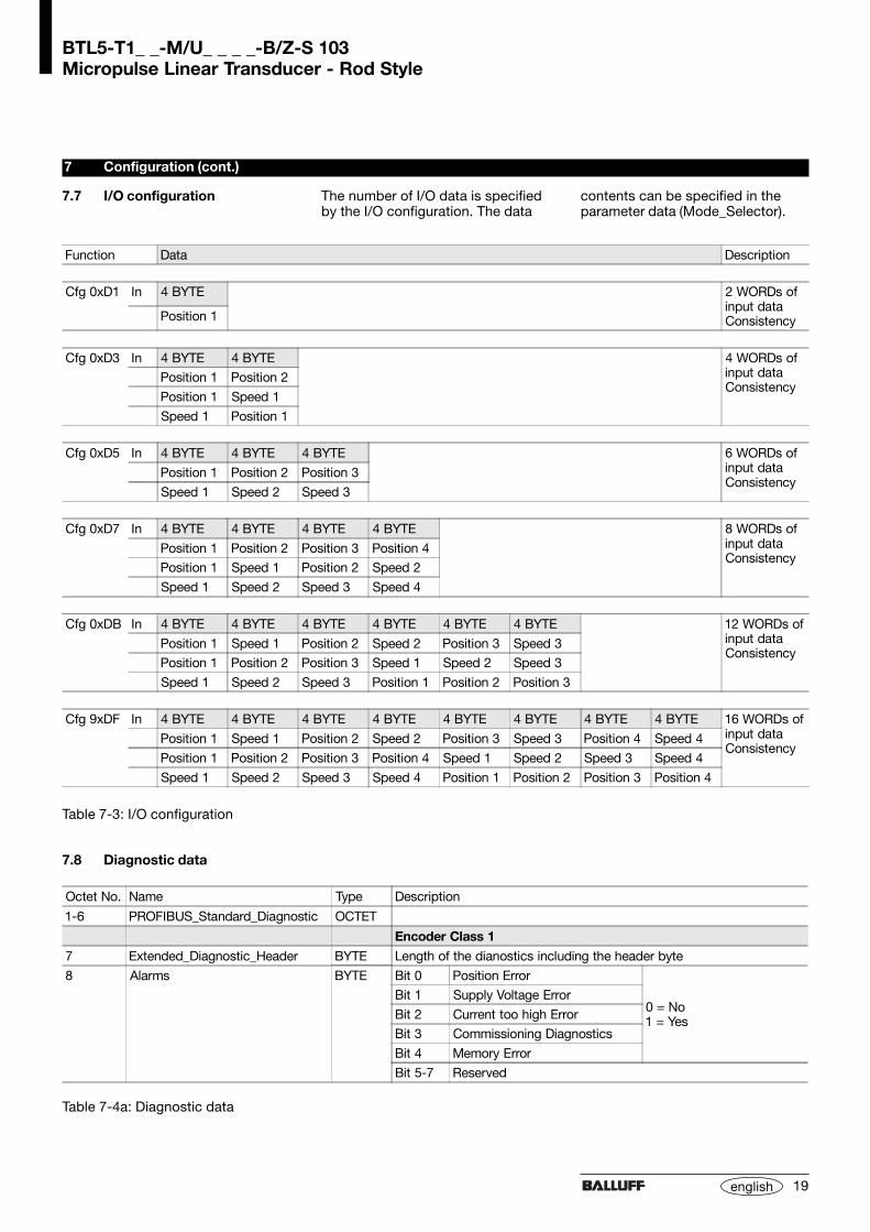
Function Data Description
Cfg 0xD1 In 4 BYTE 2 WORDs ofinput dataConsistencyPosition 1
Cfg 0xD3 In 4 BYTE 4 BYTE 4 WORDs ofinput dataConsistency
Position 1 Position 2
Position 1 Speed 1
Speed 1 Position 1
Cfg 0xD5 In 4 BYTE 4 BYTE 4 BYTE 6 WORDs ofinput dataConsistency
Position 1 Position 2 Position 3
Speed 1 Speed 2 Speed 3
Cfg 0xD7 In 4 BYTE 4 BYTE 4 BYTE 4 BYTE 8 WORDs ofinput dataConsistency
Position 1 Position 2 Position 3 Position 4
Position 1 Speed 1 Position 2 Speed 2
Speed 1 Speed 2 Speed 3 Speed 4
Cfg 0xDB In 4 BYTE 4 BYTE 4 BYTE 4 BYTE 4 BYTE 4 BYTE 12 WORDs ofinput dataConsistency
Position 1 Speed 1 Position 2 Speed 2 Position 3 Speed 3
Position 1 Position 2 Position 3 Speed 1 Speed 2 Speed 3
Speed 1 Speed 2 Speed 3 Position 1 Position 2 Position 3
Cfg 9xDF In 4 BYTE 4 BYTE 4 BYTE 4 BYTE 4 BYTE 4 BYTE 4 BYTE 4 BYTE 16 WORDs ofinput dataConsistency
Position 1 Speed 1 Position 2 Speed 2 Position 3 Speed 3 Position 4 Speed 4
Position 1 Position 2 Position 3 Position 4 Speed 1 Speed 2 Speed 3 Speed 4
Speed 1 Speed 2 Speed 3 Speed 4 Position 1 Position 2 Position 3 Position 4
Table 7-3: I/O configuration
7.7 I/O configuration
7.8 Diagnostic data
Octet No. Name Type Description
1-6 PROFIBUS_Standard_Diagnostic OCTET
Encoder Class 1
7 Extended_Diagnostic_Header BYTE Length of the dianostics including the header byte
8 Alarms BYTE Bit 0 Position Error
0 = No1 = Yes
Bit 1 Supply Voltage Error
Bit 2 Current too high Error
Bit 3 Commissioning Diagnostics
Bit 4 Memory Error
Bit 5-7 Reserved
Table 7-4a: Diagnostic data
The number of I/O data is specifiedby the I/O configuration. The data
contents can be specified in theparameter data (Mode_Selector).
BTL5-T1_ _-M/U_ _ _ _-B/Z-S 103Micropulse Linear Transducer - Rod Style
20 english
7 Configuration (cont.)
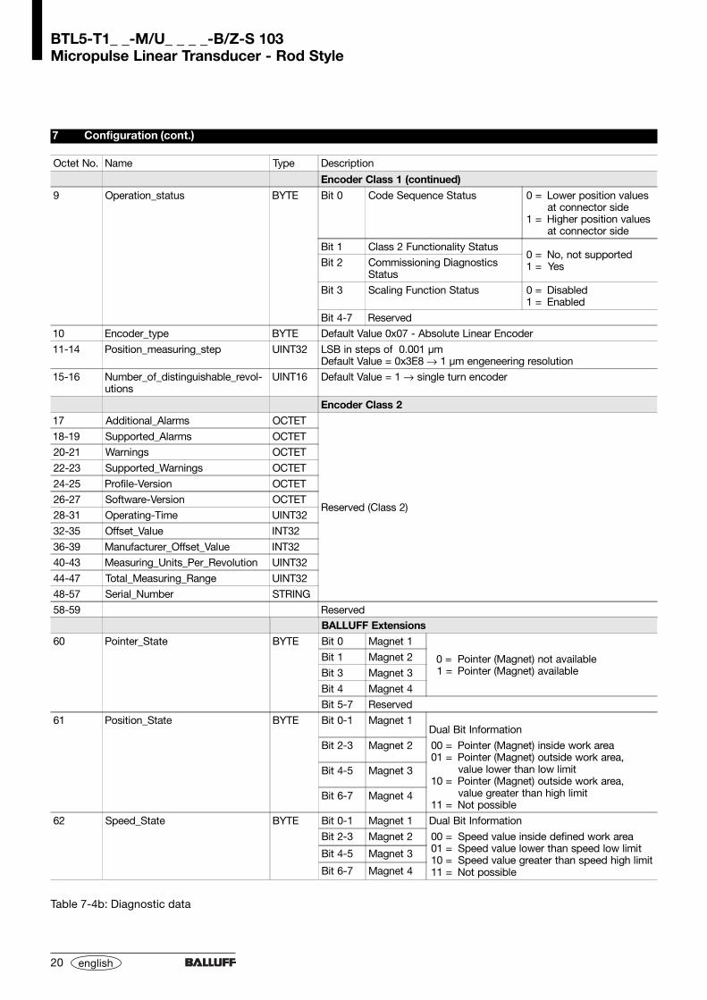
Table 7-4b: Diagnostic data
Octet No. Name Type Description
Encoder Class 1 (continued)
9 Operation_status BYTE Bit 0 Code Sequence Status 0 =
1 =
Lower position valuesat connector sideHigher position valuesat connector side
Bit 1 Class 2 Functionality Status0 =1 =
No, not supportedYesBit 2 Commissioning Diagnostics
Status
Bit 3 Scaling Function Status 0 =1 =
DisabledEnabled
Bit 4-7 Reserved
10 Encoder_type BYTE Default Value 0x07 - Absolute Linear Encoder
11-14 Position_measuring_step UINT32 LSB in steps of 0.001 µmDefault Value = 0x3E8 → 1 µm engeneering resolution
15-16 Number_of_distinguishable_revol-utions
UINT16 Default Value = 1 → single turn encoder
Encoder Class 217 Additional_Alarms OCTET
Reserved (Class 2)
18-19 Supported_Alarms OCTET
20-21 Warnings OCTET
22-23 Supported_Warnings OCTET
24-25 Profile-Version OCTET
26-27 Software-Version OCTET
28-31 Operating-Time UINT32
32-35 Offset_Value INT32
36-39 Manufacturer_Offset_Value INT32
40-43 Measuring_Units_Per_Revolution UINT32
44-47 Total_Measuring_Range UINT32
48-57 Serial_Number STRING
58-59 ReservedBALLUFF Extensions
60 Pointer_State BYTE Bit 0 Magnet 1
0 =1 =
Pointer (Magnet) not availablePointer (Magnet) available
Bit 1 Magnet 2
Bit 3 Magnet 3
Bit 4 Magnet 4
Bit 5-7 Reserved
61 Position_State BYTE Bit 0-1 Magnet 1Dual Bit Information
Bit 2-3 Magnet 2 00 =01 =
10 =
11 =
Pointer (Magnet) inside work areaPointer (Magnet) outside work area,value lower than low limitPointer (Magnet) outside work area,value greater than high limitNot possible
Bit 4-5 Magnet 3
Bit 6-7 Magnet 4
62 Speed_State BYTE Bit 0-1 Magnet 1 Dual Bit Information
Bit 2-3 Magnet 2 00 =01 =10 =11 =
Speed value inside defined work areaSpeed value lower than speed low limitSpeed value greater than speed high limitNot possible
Bit 4-5 Magnet 3
Bit 6-7 Magnet 4

21
BTL5-T1_ _-M/U_ _ _ _-B/Z-S 103Micropulse Linear Transducer - Rod Style
english
Resolution, selectablein steps of 5 µmVelocity, selectablein steps of 0.1 mm/s
Sampling rate fStandard = 1 kHz
Non-linearity ± 30 µmHysteresis < 1 LSBRepeatability < 2 LSB(resolution + hysteresis)Temperature coefficient< (6 µm + 5 ppm * nominal length)/KShock loading 100 g/6 msper IEC 68-2-27 1
Continuous shock 100 g/2 msper IEC 68-2-29 1
Vibration 12 g, 10 to 2000 Hzper IEC 68-2-6 1
(take care to avoid inherent reso-nances of protective tube)Pressure up to 600 barwhen installed in a hydraulic cylin-der1 Individual specifications as per Balluff
factory standard
8.1 Dimensions, weights,ambient conditions
Nominal length < 4000 mmDimensions ➥➥➥➥➥ Fig. 3-2Weight approx. 2 kg/mHousing anodized aluminumPressure tube stainless steel 1.4571diameter 10,2 mmwall thickness 2 mme-modulus ca. 200 kN/mm2
Mounting threadsM18 x 1.5 or 3/4"-16UNFOperating temp. –40 °C to +85 °CHumidity < 90%, non-condensingProtection class per IEC 529 IP 67when closed up
8 Technical Data
Typical values at DC 24 V and 25 °C. Ready for operation at once, full accuracy after warm-up. With magnet BTL-P-1013-4R, BTL-P-1013-4S or BTL-P-1012-4R:
8.2 Supply voltage (external)
Regulated supply voltageBTL5-_1... DC 20 to 28 VRipple < 0.5 Vpp
Current draw 2 < 130 mAInrush < 3 A/0.5 msPolarity reversal protection built-inOvervoltage protectionTranszorb diodesElectric strengthGND to housing 500 V2 depending on load on VP (repeater,
bus terminator)
8.3 Control signals
RxD/TxD-N, RxD/TxD-P, Data GNDper EN 50170
8.4 Connection to theprocessor
Cable ➥➥➥➥➥ Fig. 4-1Twisted-pair, shielded.Max. fieldbus length 1200 m
8.5 Included in shipment
Transducer (not incl. magnet)➥➥➥➥➥ Fig. 3-2
GSD file 3.5" floppy
8.6 Magnets(order separately)
Magnets BTL-P-1013-4R,BTL-P-1013-4S, BTL-P-1012-4RDimensions ➥➥➥➥➥ Fig. 3-4Weight approx. 10 gHousing anodized aluminumOperating temp. –40 °C to +85 °C
Magnets BTL5-P-4500-1(Electromagnet)Weight approx. 90 gHousing plasticOperating temp. –40 °C to +60 °C
8.7 Accessories (optional)
For PROFIBUS connections:
Connector BKS-S103-00Dimensions ➥➥➥➥➥ Fig. 4-3
Connector BKS-S105-00Dimensions ➥➥➥➥➥ Fig. 4-6
Cable with connectorBKS-S103/GS103-CP-_ _ _Dimensions ➥➥➥➥➥ Fig. 4-5Lengths: 00.3; 02.0; 05.0; 10.0 m
Termination resistorBKS-S105-R01Dimensions ➥➥➥➥➥ Fig. 4-7
For power supply:
Cable with connectorBKS-S48-15-CP-_ _Dimensions ➥➥➥➥➥ Fig. 4-4Lengths: 02; 05; 10 m
No.
821
071
E •
Ed
ition
010
2; s
pec
ifica
tions
sub
ject
to
chan
ges
with
out
notic
e.