Embed Size (px)
Citation preview
By
D. Brant Bennion, Hycal Energy Research Laboratories Ltd.F. Brent Thomas, Hycal Energy Research Laboratories Ltd.Eric C. Crowell, Hycal Energy Research Laboratories Ltd.
Bruce Freeman, Isotopes Canada Ltd.
Prepared for presentation at the 1995 1 st Annuallntemational Conference on Reservoir ConformanceProfile Control Water & Gas Shutoff, August 21-23, 1995, Houston, Texas
Abstract It also addresses some of the environmentalconcerns that may cause co~anles to refrainfrom using tracers as a viable tool Inunderstanding flow units and quantifying by-passed pay.
When evaluating a reservoir for optimizationpotential, an interwell tracer program is avaluable tool to be utilized as a means to betterunderstand the by-passed pay areas of thereservoir that can cause poor conformance.Tracers can be an effective tool also whenincorporated into the development of a detailedreservoir model so that the geologist andreservoir engineer have a better understanding ofthe flow units that exist between wells and of theinitial oil, water and gas saturations which mayexist in the reservoir.
Introduction
Although many of the world's reservoirs havereached maturity in relation to oil production(even though OOIP still exceeds 75% in manycases), the question remains, "Is there recoverytechnology available that will allow more oil to beproduced from these reservoirs?". Manytechnical people answer, "Yes, if we had a betterunderstanding of the reservoir so that we couldidentify potential unswept zones". The keycomponent to helping us unlock the remainingreserves in mature fields is to have a betterunderstanding of reservoir heterogeneities whichsignificantly affect where the fluids are or are notflowing through the reservoir'. By applying anintegrated reservoir analysis approach (geology,
This paper addresses the benefits that tracerscan provide, both on a rnacroscale andmicroscale basis, to more effectively determineand model flow units in the reservoir. The paperuses case examples to illustrate the application oftracers to improve production. It shows whichtracers provide the best results and gives a betterunderstanding of saturations, sampling andanalytical techniques used to obtain quality data.
geophysics, coring, reservoir and productionengineering and petrophysics) a morecomprehensive understanding of how the fluidsare flowing through the porous media will beachieved2.
tracer tests can also provide quantitativeinfonnation conceming the rate of movement andvolume of fluid that is produced at each well.This data provides clues concerning the earlybreakthrough characteristics of a flood thatstrongly affect its ultimate recovery. Therefore,pressure transient analysis and interwell tracerstudies are complementary, not competetive,tests3. The main objective of this paper is toaddress how tracers allow one to moreeffectively:
This information is valuable in providing dataon how to characterize the reservoir but it islimited to information in the near wellbore region.Application of geostatistical techniques can
integrate a variety of data to extrapolate interwellproperties, but these still represent non-quantifiable properties in most situations. It iswith the additional knowledge of fluid flowbetween individual wells that a properunderstanding of the reservoir can be obtained.
characterize interwell fluid flowobtain better measurements of S. and So inthe reservoir's flow units through improvedcoring techniques
The benefits of tracers are: Through improved knowledge of how andwhere the fluids are moving between wells andhow much by-passed pay remains, technologiescan be identified that will be best suited tooptimize mature reservoirs.
1 Improved understanding of how and whereinjected fluids are or are not flowing betweenwells.
2. Better identification of the amount ofhydrocarbons remaining in individual flowunits as a result of poor sweep efficiency.This information is obtained by measuring Swand/or So from preserved core obtained inswept zones, or by using reservoir modellingand material balance techniques to quantifythe volume of oil remaining in a by-passedzone based upon the results of the tracerprogram.
Using Tracers to Characterize Interwell Fluid~
When evaluating the upside potential of amaturing reservoir, a tracer program can providevaluable information with respect to optimizingproduction. This information includes:
1. Flow direction - Where are fluids flowing?What injectors are influencing variousproducing wells?Over the years, two methods have been
utilized to obtain interwell fluid flow characteristics- pressure transient analysis and interferencetests and interwell tracer programs. Both testscomplement each other by providing keyinformation on how the fluids move betweenwells. Pressure transient analysis tests measureaverage properties between wells and are goodmeasurement techniques for determining ifpermeability trends exist. Interference tests canquantify if individual wells exhibitinterconnectiveness and some indication of thedegree of interconnectiveness. On the otherhand, interwell tracer tests provide valuableinformation about the extensiveness ofheterogeneity that exists to clarify the averagesmeasured by the interference tests. I nte rwe II
Case Examples -
i)ii)
waterfloodinggas injection (WAG)
I) Waterflooding - Is the waterfloodmaximizing reservoir sweep efficiency?
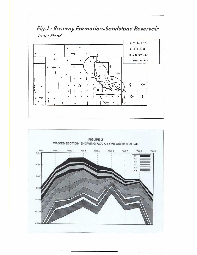
While instituting a multi-tracer program, ina sandstone reservoir in Alberta, to optimize anexisting waterflood (direction, rate and continuity),it was discovered, upon injection of four differenttracers (Cobolt 60, Nickel 63, Cesium 137 andTritiated HO) into separate injection wells, thatthe tritiated HO (HTO) broke through at aproduction well within six months (three months
.,
before any of the other tracers began appearingat the production wells). Following its initialsweep through the reservoir, the HTO thencompleted a second, more extensive, sweepevidenced by a much higher concentration ofHTO at the respective production wells. Thisdouble sweep Indicates that there was a highpermeability sand lense, which provided greaterdefinition of the size and conductivity of the highpermeablity streak within the geological model.This improved model could then help reduce therisk in developing a water shut-off strategy on thehigh permeability sand lense in selected wells sothat reservoir conformance to water injectioncould be improved. (Figure 1)
relationships of concern when coupling micro-scale geology with the phase behaviors.
(1)
M<~JJ.g (2)
Sulface At,!!. « ..!.0
ii) Gasfloodlng (WAG) - Is the waterfollowing the solvent to maximize sweepefficiency?
(3)~
An area of interest over the years hasbeen the application of gas injection technologyin enhanced oil recovery. Specifically, thosegases classified as "miscible" have been appliedin the field and, in some cases, the results havebeen somewhat less than expected. There area number of technical reasons why so-called"miscible" floods have performed inadequately4,but such discussion is, for the most part, beyondthe scope of this presentation. Some of the morerecent work5 has indicated that depending uponthe testing used to evaluate the process, theextent of the interfacial tension reduction actuallycan pre-dispose a gas injection project tosuccess or failure.
Equation (1) provides the capillarypressure equation, which simply states that thecapillary pressure which Is holding the oil in theporous media is proportional to the interfacialtension between the displaced and displacingfluid provided by the diameter of the porousfeature in which the two-phase system is present.Equation (2) shows the standard fractional flowequation where the mobility ratio 8M8 isproportional to the viscosity ratio, and Equation(3) shows the standard proportionality betweensurface area and volume.
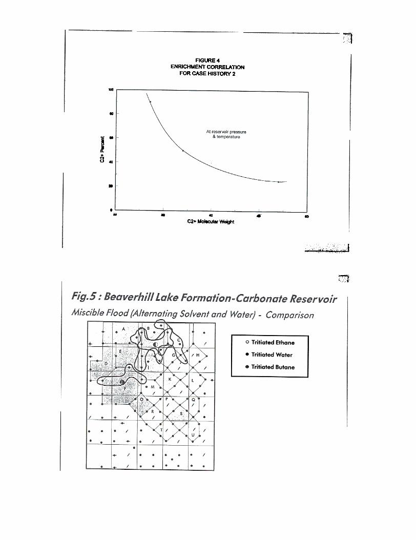
The way in which a gas will displace anoil depends upon the compromise reachedbetween these three relationships. Couplingthese three relationships in the context of themacroscale and microscale geology leads to theidentification of whether a system will be mobility-or interfacial tension-dominated. There are aseries of lab tests that can be used to identify theextent of mobility vs interfacial tensiondomination, but sometimes floods have beenimplemented in the field on the basis of testingwhich is less than sufficient. For example, Figure4 illustrates the standard plot which is used manytimes for evaluating an appropriate gas design.The plot shown in Figure 4 describes theconditions in terms of the C2+ percentage as wellas the C2+ molecular weight which define a
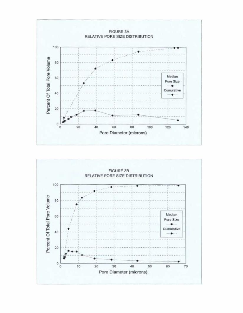
The basis for this Is shown in Figure 2where one observes a typical cross-section of areservoir. In this figure, the geology indicatesthat there are approximately six separate flowunits present. Figure 3 illustrates the microscalegeology associated with two of these flow units.In Figure 3A, a pore size distribution is observedwhere the bulk of the porous features exhibit acharacteristic diameter greater than 20 microns,whereas in Figure 38, over 90% of the porousfeatures are exhibited at a characteristic diameterof less than 20 microns. In such a case, the flowcharacteristics of gas and oil, and for that matter,water and oil, in these various flow units, can bevery different. The following equations show the
3
specific interfacial tension value. In the past,interfacial tension has been viewed by some asa sufficient condition for gas design and,consequently, once the relationship in Figure 4had been identified, the design was completed.However, from more recent experience, we knowthat because the efficacy of a gas is going to bedependent upon the compromise between theinterfacial tension and mobility, this balance is notindicated in Figure 4. For example, in someenriched gas displacements In the field, thosegases which have a low molecular weight of C2+often exhibit a bias towards mobility domination;whereas those solvents which have a higher C2+molecular weight tend to be more associated withan 1FT domination. Moreover, in some cases,the higher C2+ percentage at low molecularweight have a disadvantage from a gravitystabilization standpoint and, therefore, anincreased pressure must be applied so that eventhough the potential 1FT Is the same, theexpected sweep is going to be comparable also.These are some of the indicators that can beSCOped in the lab, but which are often omitted.
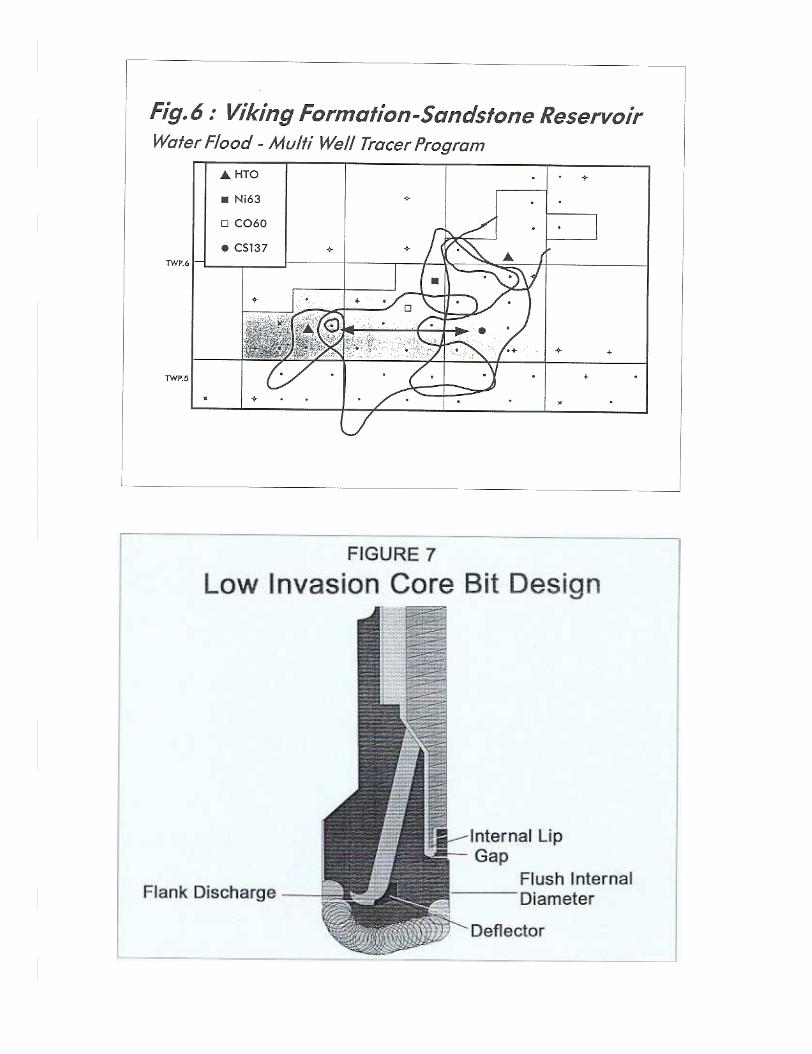
fractures, etc.). As illustrated by Figure 6, from awaterflooded sandstone reservoir in Alberta, inthe centre of the pool, none of the four tracers(HTO, Ni63, Co6O, Cs137) injected swept thissection of the reservoir. The conclusion wasmade that there was a tight streak surroundingthis well. From this information the waterinjection pattem was altered to eliminate this tightzone.
Water-Based Tracers
For water soluble tracers which areadded to injection water, over the last few yearsmost of the interwell tracer studies have beenconducted using radioactive isotopes versuschemical-based tracers as isotopes are morereliable and accurate. Chemical tracers havebeen largely abandoned due to numerousproblems including adsorption of the chemicalonto the rock system, destruction of the tracer(oxidization, bacteria or precipitated out ofsolution), natural interference or contaminationwhich make analysis difficult (ie. fluorescentcompounds), and the large volumes and expenserequired for accurate detection (ie. alcohol =several thousand litres vs HTO 5 ml).
This brings us to the benefit of applyingtracers to the field. For example. Figure 4 showsthe irregular patterns of gas breakthrough whencompared to the path which the water follows.Because of different interfacial tensions betweenthe gas and the water in the presence of oil. theaccessibility, from a microscale perspective andin light of Equation (1), will predispose a gas toflowing in a direction different than that of thewater as illustrated in Figure 5 from a gasinjection (WAG) project in Alberta.
Due to advances made in radioisotopetechnology many safe radioisotopes can be usedalthough tritium is, by choice, more widely usedbecause it is the safest beta-emitter. Tritiatedwater emits electrons which cannot pass throughpaper or skin, versus gamma-emitters which emitgamma rays which can pass through mostmaterials. Greater expense is involved in atracer program utilizing gamma tracers (CobaltSO, Cesium 137, Cesium 134) because of safetyrequirements generally i~osed by the regulatoryagencies. Transportation of gamma tracers,particularly to foreign or remote sites, can also beproblematic. Table 1 provides a list of varioustypes of water-based radioisotope tracers andconcentrations to consider for field use.)
2. Reservoir Continuity - The informationreceived about which injector influences whichproducer in terms of rate (breakthrough times)and what percentage of fluid (volume) is goinginto each well can provide abundant informationabout reservoir continu~ (high permeabilitystreaks, unswept zones, shale barriers andpermeability and porosity lenses).
3. Reservoir Anomalies - Are there areasof the reservoir that tracers have not sweptthereby allowing valuable information to begained as to macroscale heterogeneities (tightzones, lenses of porosity and permeability, faults,
Gas Tracers
When designing a gas tracer program, itis important to determine gas tracer partitioninginto the oil phase because the greater the
4.
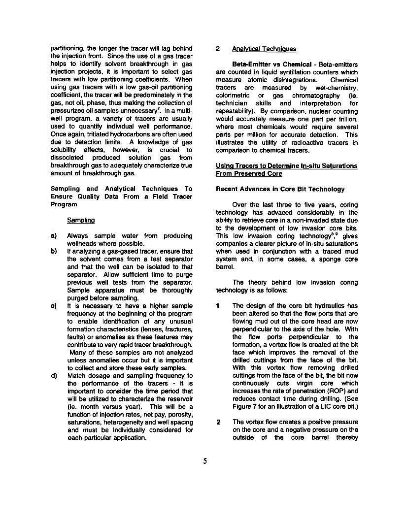
partitioning, the longer the tracer will lag behindthe injection front. Since the use of a gas tracerhelps to identify solvent breakthrough in gasinjection projects, it is irr.,ortant to select gastracers with low partitioning coefficients. Whenusing gas tracers with a low gas-oil partitioningcoefficient, the tracer will be predominately in thegas, not oil, phase, thus making the collection ofpressurized oil samples unnecessary7. In a multi-well program, a variety of tracers are usuallyused to quantify indMduaJ well performance.Once again, tritiated hydrocarbons are often useddue to detection limits. A knowledge of gassolubility effects, however, is crucial todissociated produced solution gas frombreakthrough gas to adequately characterize trueamount of breakthrough gas.
2 Analvtical Technlaues
Be.Emltter vs Chemical - Beta-emittersare counted in liquid syntillation counters whichmeasure atomic disintegrations. Chemicaltracers are measured by wet-chemistry,colorimetric or gas chromatography (ie.technician skills and interpretation forrepeatability). By comparison, nuclear countingwould accurately measure one part per trillion,where most chemicals would require severalparts per million for accurate detection. ThisIllustrates the utility of radioactive tracers incomparison to chemical tracers.
Using Tracers to Determine In-situ SaturationsFrom Preserved Core
Sampling and Analytical Techniques ToEnsure Quality Data From a Field TracerProgram
Recent Advances In Core Bit Technology
Over the last three to five years, coringtechnology has advaced considerably in theability to retrieve core in a non-invaded state dueto the development of low invasion core bits.This low invasion coring technologyB ,9 givescompanies a clearer picture of in-situ saturationswhen used in conjunction with a traced mudsystem and, in some cases, a sponge corebarrel.
SamDlina
a)
b)
The theory behind low invasion coringtechnology is as follows:
c)
Always sample water from producingwellheads where possible.If analyzing a gas-gased tracer, ensure thatthe solvent comes from a test separatorand that the well can be Isolated to thatseparator. Allow sufficient time to purgeprevious well tests from the separator.Sample apparatus must be thoroughlypurged before sampling.It is necessary to have a higher samplefrequency at the beginning of the programto enable identification of any unusualformation characteristics (lenses, fractures,faults) or anomalies as these featuras maycontribute to very rapid tracer breakthrough.Many of these samples are not analyzed
unless anomalies occur but it is importantto collect and store these earty samples.Match dosage and sampling frequency tothe performance of the tracers - it isimportant to consider the time period thatwill be utilized to characterize the reservoir(ie. month versus year). This will be afunction of injection rates, net pay, porosity,saturations, heterogeneity and well spacingand must be individually considered foreach particular application.
1 The design of the core bit hydraulics hasbeen altered so that the flow ports that areflowing mud out of the core head are nowperpendicular to the axis of the hole. Withthe flow ports perpendicular to theformation, a vortex flow is created at the bitface which improves the removal of thedrilled cuttings from the face of the bit.With this vortex flow removing drilledcuttings from the face of the bit, the bit nowcontinuously cuts virgin core whichincreases the rate of penetration (ROP) andreduces contact time during drilling. (SeeFigure 7 for an illustration of a LlC core bit.)
d)
2 The vortex flow creates a positive pressureon the core and a negative pressure on theoutside of the core barrel thereby
5

minimizing invasion tendencies on thecore by drawing the circulating mudsystem away from the core face.
extraction must be used which can result inerrors due to commutation effects. Preferredtracers are:
3. The placement of an Inner barrel very closeto the cutting surface of the bit enhancesthe ability to minimize fluid invasion as thecore enters the Inner barrel immediatelyafter being cut by the bit.
Tritium. (HTO) - radioactive (Beta-emitter)Deuterium (D2O) - non-radioactive (heavywater)
. Tritium has some advantages in that it is
considerably less expensive than deuterium, doesnot naturally exist in formation waters and hasmuch lower detection limits than deuterium.
Fluid System Design to Obtain Preserved Core
In order to obtain a preserved core toevaluate not only in-situ saturations but otherproperties such as wettability, capillary pressureor relative permeability, using the low invasioncore (LlC) technology, further refinements needto be made to the mud system so that the LIC bitcan perform effectively. This is due to the factthat some mud invasion may still occur,particularly in higher permeability formations orwith high compressibility (gas) reservoirs. Themud system refinements to maintain native statewettability include:
Case.
Objective for Coring: To determine initial watersaturation and oil in place to evaluate waterflood
feasibility.
. Sunburst sand
. Oil reservoir
. Average permeability - 100-200 mD
. Average porosity - 25%
Neutral pH
2. No chemical additives (surfactants,lignosulphonates, corrosion inhibitors, polarmud additives, mud thinner caustics andacidic additives).
conventional core and logs calculate 45%water saturationdrilled preserved core using a low invasioncoring technology and a water-based mudwith a resin system for fluid losspreserved core measures 300/0, an increaseof 27% OOIPpreserved core, logs and build-up analysisshow negligible skin indicating minimalfomlation damage
3. Radioactive tracers to quantify the amountof invasion due to drilling to determine theinitial water saturation through a materialbalance calculation. If a sponge core innerbarrel is used vs an aluminum or fibreglasstube then Initial oil and gas saturations mayalso be quantified if the core is obtained ina non-flushed or minimally flushed state.
Results - An addition of 3 million barrels ofrecoverable oil by optimizing the existingwaterflood.
Case II
Types of Tracers Objective for Coring: To determne watersaturation and optimize fracturing program toinvestigate concerns with phase trapping ofwater-based fracture fluids.
From experience, radioactive and stableisotope (HTO and D2O) tracers are preferredbecause chemical tracers have the tendency tobe adsorbed into microporous clays or readilydecompose and be subject to contaminationissues. If the water saturation in the core is toolow to be removed for analysis by non-destructivemeans (ie. centrifucation) then crushing and
. Gething sand
. Gas reservoir
. Average penneabllity - 1-10 mD
. Average porosity - 7-8%
6
conventional coring indicated insitu watersaturation was 40% and correlates with logsdrilled preserved core with an oil-based mudpreserved core logs Indicated insitu watersaturation is 15-20%
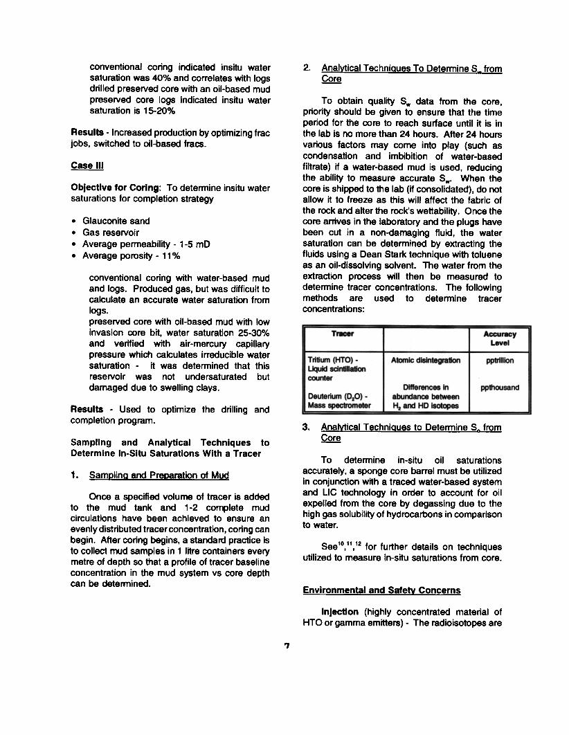
2. Analvtical TechniQues To Detennine S. from.QQ!:!
To obtain quality S. data from the core,priority should be given to ensure that the timeperiod for the core to reach surface until it is inthe lab is no more than 24 hours. After 24 hoursvarious factors may come into play (such ascondensation and imbibition of water-basedfiltrate) if a water-based mud is used, reducingthe ability to measure accurate S.. When thecore is shipped to the lab (if consolidated), do notallow it to freeze as this will affect the fabric ofthe rock and alter the rock's wettability. Once thecore arrives in the laboratory and the plugs havebeen cut in a non-darnaging fluid, the watersaturation can be determined by extracting thefluids using a Dean Stark technique with tolueneas an oil-dlssolving solvent. The water from theextraction process will then be measured todetermine tracer concentrations. The followingmethods are used to determine tracerconcentrations:
Results - Increased production by optimizing frac
jobs, switched to oil-based fracs.
Case III
Objective for Coring: To determine insitu watersaturations for completion strategy
. Glauconite sand
. Gas reservoir
. Average permeability - 1-5 mD
. Average porosity - 11%
conventional coring with water-based mudand logs. Produced gas. but was difficult tocalculate an accurate water saturation fromlogs.preserved core with oil-based mud with lowinvasion core bit, water saturation 25-30%and verified with air-mercury capillarypressure which calculates irreducible watersaturation - it was determined that thisreservoir was not undersaturated butdamaged due to swelling clays.
TrKet' AccuracyLevel
I Tritium (HTO) -
liquid sdntillatioo
caJnter
A1omic disintegration pptrillk>n
Differences In
abuOOance betweenHz arwJ HD Isot~
ppttnJsandI DeuterkJm (D.O) .Mass specIromeI8rResults - Used to optimize the drilling and
completion program. 3. AnalYtical TechniQues to Determine S~ from~Sampling and Analytical Techniques to
Determine In-Situ Saturations With a TracerTo determine in-situ oil saturations
accurately, a sponge core barrel must be utilizedin conjunction with a traced water-based systemand LlC technology in order to account for oilexpelled from the core by degassing due to thehigh gas solubility of hydrocarbons in comparisonto water.
1. SamDlina and Preoaration of Mud
Once a specified volume of tracer is addedto the mud tank and 1-2 complete mudcirculations have been achieved to ensure anevenly distributed tracer concentration, coring canbegin. After coring begins, a standard practice isto collect mud samples in 1 litre containers everymetre of depth so that a profile of tracer baselineconcentration in the mud system vs core depthcan be determined.
See 1°,11,12 for further details on techniquesutilized to measure in-situ saturations from core.
Environmental and SafelY Concerns
Injection (highly concentrated material ofHTO or gamma emitters) - The radioisotopes are
?
REFERENCESproduced in such infinitesimal quantities that onlysophisticated equipment can detect them.Therefore, there are no health or environmentalhazards whatsoever when sampling, storing ortransporting the sa~les (Ie. for HTO a fewpcVml in a typical reservoir water vs drinkingwater standard of 1000 pcVml).
1 Ti, G., Ogbe. D.O. Munly, W., Hatzignatiou,D.G., "Use of Flow Units as a Tool forReservoir Description: A Case Study",SPEFE (June 1995) 122-128.
Takur, G.C., "What is ReservoirManagement?", SPE Paper 26289 presentedat the 1994 SPE Permian Basin Oil & GasRecovery Conference held in Midland, TX,March 16-18.
2.The only area In which environmental and
health hazards may exist is with the injection ofradioisotopes. For this reason, injection isconducted by a team of highly trained personnel.This group ensures that no trace of the tracerremains and that all of the material has beeninjected below surface. Naturally the use of softbeta tracers have further imporoved the safety ofthe injections.
3. Brigham, W.E. and Abbaszadeh-Dehghani,M., "Tracer Testing for ReservoirDescription", JfI (May 1987), 519-527.
Thomas, F.B., Holowach, N., Zhou, X.,Bennion, D.B., Bennion, D.W., "Miscible orNear-Miscible Gas Injection, Which IsBetter?", Paper SPE/DOE 27811 presentedat the SPE/DOE Ninth Symposium onImproved Oil Recovery held in Tulsa,Oklahoma, April 17-20, 1994.
4.
CONCLUSIONS
An interwell tracer program is an effectivetool for identifying areas of by-passed paydue to poor reservoir conformance.
Thomas, F .B., Okazawa, T., Erian, A., Zhou,X., Bennion, D.B., Bennion, D.W., .DoesMiscibility Matter in Gas Injection., Paper No.95-51 presented at the 46th AnnualTechnical Meeting of the Petroleum Societyof CIM in Banff, Alberta, May 14-17, 1995.
2. An interwell tracer program providesvaluable information concerning flowdirection, reservoir continuity and reservoiranomalies.
5.
3. Beta-emitter radioisotopes are becomingmore widely used due to low health andenvironmental concerns and accurate,reliable measurements (HTO, N163, Tc99,tritiated isopropyl alcohol).
D'Hooge, J.A., Sheely, C.O., and Williams,B.J., "Interwell Tracers - An EffectiveReservoir Evaluation Tool: West SumatraField Results", fl (May 1981) 779-82.
6.
4. Radioisotope and stable isotope tracers(HTO and D2O) are a valuable tool whenused with low invasion coring (LtC) todetermine 5. and So'
7. Anderson, J.H., Laurie, A.A., Loder, W.A.Jr., Kennedy, P., .Brassey Field MiscibleRood Management Program FeaturesInnovative Tracer Injection., SPE Paper24874 presented at the 1992 SPE AnnualTechnical Conference held In Washington,D.C., Oct. 4-7.
ACKNOWLEDGEMENTS
The authors wish to express appreciation toLany Buchinski of DB Stratabit (Canada), PeterChurcher of PanCanadian Petroleum Ltd. andNadia Pallatt for their technical support and toVivian Whiting and Maggie Irwin of Hycal EnergyResearch Laboratories Ltd. for their work inpreparing the manuscript and figures.
Clydesdale, G., Leseultre, A., and Lamine,E., .Core Bit Design Reduces Mud Invasion,Improves ROp., Oil & Gas Journal (August8, 1994) 51-57.
8.
8
9. Bobrosky, D., and Osmak, G., "AntiwhirlPDC Bits Increased Penetration Rates inAlberta Drilling", Oil & Gas Journal (July 5,1993) 41-46.
10. Pallatt, N., Stockden, I., Mitchell, P.S. andWoodhouse, R., "Low Invasion Coring GivesNative Reservoir Water Saturations", 1991European SPWLA, Thames.
11. lasserre, D. and Chao, C.F., "ExperienceWith Determination of Water Saturation FromCore in The Cossack Field", APEA Journal1993.
12. Durandeau, M., EI-Emarn, M., Anis, A.,Fanti, G., .Successful Field Evaluation of theEfficiency of a Gas Gravity DrainageProcess by Applying Recent Developmentsin Sponge Coring Technique in a Major OilField., SPE Paper 29809 presented at the1995 SPE Middle East Oil Show held inBahrain, March 11-14.
9
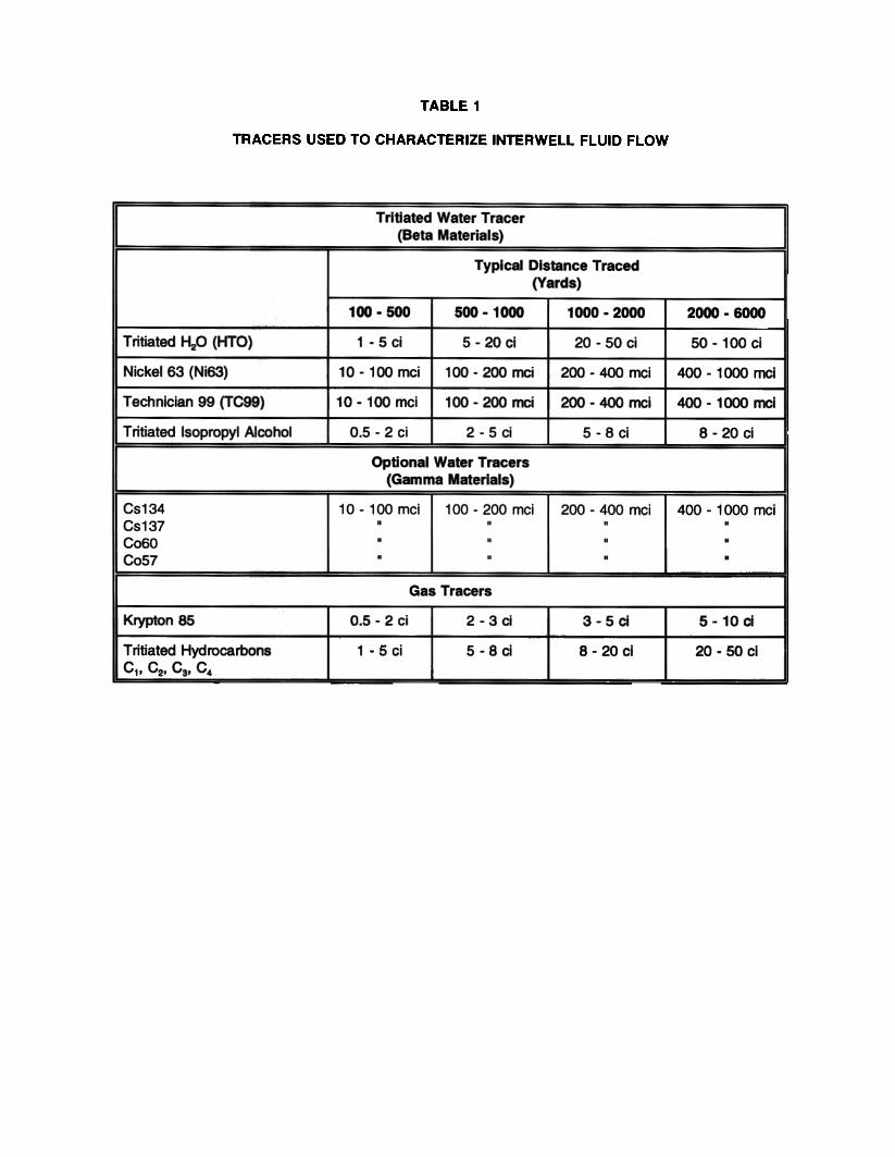
TABLE 1
TRACERS USED TO CHARACTERIZE INTERWELL FLUID FLOW
Tritiated Water Tracer(Beta Materials)
Typical Distance Traced(Yards)
100 - 500 500 - 1000 1000 - 2000 2000 - 6000
Tritiated ~O (HTO) 1.5ci 5-20cl 2O-SOci 50 - 100 ci
Nickel 63 (Ni63~ 10 - 100 mcl 100 - 200 nx:i 200 - 400 ~i 400 - 1 000 n'K:i
Technician 99 (TC99) 10 - 100 mci 100 - 200 mci 200 - 400 nx:i 400 - 1 000 nx:i
Tritiated Isopropyl Alcohol 0.5 - 2 ci 2-~ci 5-8ci 8-20ci
Optional Water Tracers(Gamma Materials)
Cs134Cs137CoSOCo57
10 1 00 mci...
100-200mci...200 - 400 mci
.
.
.
400 - 1 000 nx:i...
Gas Tracers
Krypton OS 0.5 - 2 cl 2-3ci 3-5a 5-10a
Tritiated HydrocarbonsC1- C2- Ca- C4
1-5ci S-8ci 8 - 20 ci 2O-SOci
P1;c
FIGURE 4ENRICHMENT CORRELATION
FOR CASE HISTORY 2
11»
.J .tt.(.) 40
... . ~
C2+ Molecular ~ht. 10
~
~O";,,t
0 Tritiated Ethane
. Tritiated Water
. Tritiated Butane