Embed Size (px)
Citation preview
FOR MORE INFORMATION PLEASE VISIT US ON THE WEB ATMRPBIKE.COM
OR CALL US AT (970)241-3518, WE’LL BE GLAD TO ASSIST YOU!
580 NORTH WESTGATE DR.GRAND JUNCTION, CO 81505
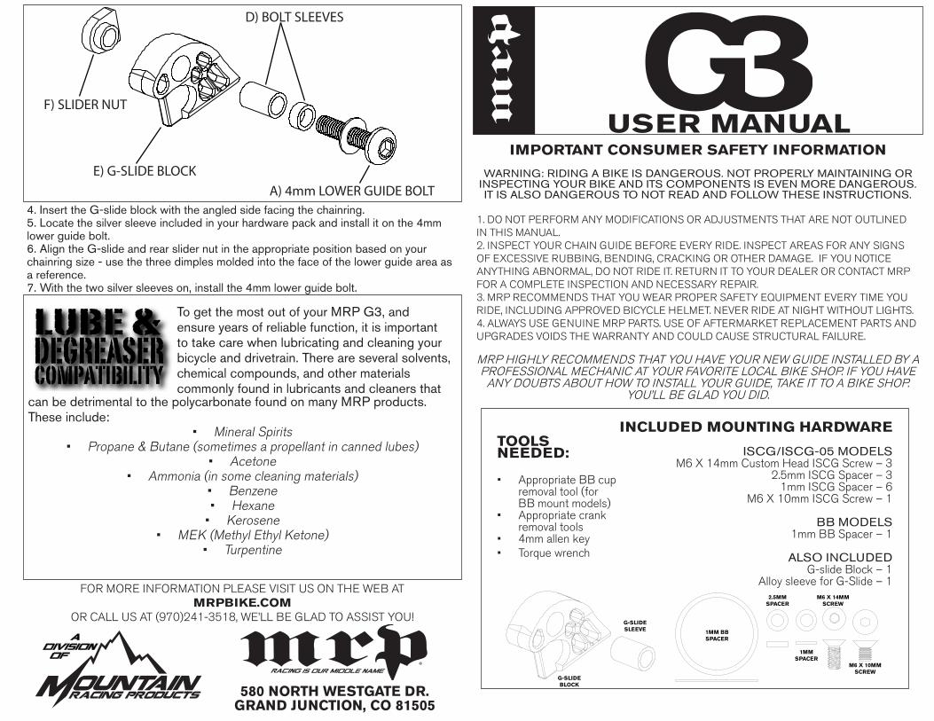
USER MANUALIMPORTANT CONSUMER SAFETY INFORMATION
WARNING: RIDING A BIKE IS DANGEROUS. NOT PROPERLY MAINTAINING OR INSPECTING YOUR BIKE AND ITS COMPONENTS IS EVEN MORE DANGEROUS. IT IS ALSO DANGEROUS TO NOT READ AND FOLLOW THESE INSTRUCTIONS.
1. DO NOT PERFORM ANY MODIFICATIONS OR ADJUSTMENTS THAT ARE NOT OUTLINED IN THIS MANUAL.2. INSPECT YOUR CHAIN GUIDE BEFORE EVERY RIDE. INSPECT AREAS FOR ANY SIGNS OF EXCESSIVE RUBBING, BENDING, CRACKING OR OTHER DAMAGE. IF YOU NOTICE ANYTHING ABNORMAL, DO NOT RIDE IT. RETURN IT TO YOUR DEALER OR CONTACT MRP FOR A COMPLETE INSPECTION AND NECESSARY REPAIR.3. MRP RECOMMENDS THAT YOU WEAR PROPER SAFETY EQUIPMENT EVERY TIME YOU RIDE, INCLUDING APPROVED BICYCLE HELMET. NEVER RIDE AT NIGHT WITHOUT LIGHTS.4. ALWAYS USE GENUINE MRP PARTS. USE OF AFTERMARKET REPLACEMENT PARTS AND UPGRADES VOIDS THE WARRANTY AND COULD CAUSE STRUCTURAL FAILURE.
MRP HIGHLY RECOMMENDS THAT YOU HAVE YOUR NEW GUIDE INSTALLED BY A PROFESSIONAL MECHANIC AT YOUR FAVORITE LOCAL BIKE SHOP. IF YOU HAVE
ANY DOUBTS ABOUT HOW TO INSTALL YOUR GUIDE, TAKE IT TO A BIKE SHOP. YOU’LL BE GLAD YOU DID.
M6 X 14MMSCREW
M6 X 10MMSCREW
2.5MMSPACER
1MMSPACER
1MM BBSPACER
G-SLIDEBLOCK
G-SLIDESLEEVE
TOOLS NEEDED:
• Appropriate BB cup removal tool (for BB mount models)
• Appropriate crank removal tools
• 4mm allen key• Torque wrench
INCLUDED MOUNTING HARDWARE
ISCG/ISCG-05 MODELSM6 X 14mm Custom Head ISCG Screw – 3
2.5mm ISCG Spacer – 31mm ISCG Spacer – 6
M6 X 10mm ISCG Screw – 1
BB MODELS1mm BB Spacer – 1
ALSO INCLUDED
G-slide Block – 1 Alloy sleeve for G-Slide – 1
®
D) BOLT SLEEVES
E) G-SLIDE BLOCKA) 4mm LOWER GUIDE BOLT
F) SLIDER NUT
4. Insert the G-slide block with the angled side facing the chainring.5. Locate the silver sleeve included in your hardware pack and install it on the 4mm lower guide bolt.6. Align the G-slide and rear slider nut in the appropriate position based on your chainring size - use the three dimples molded into the face of the lower guide area as a reference.7. With the two silver sleeves on, install the 4mm lower guide bolt.
To get the most out of your MRP G3, and ensure years of reliable function, it is important to take care when lubricating and cleaning your bicycle and drivetrain. There are several solvents, chemical compounds, and other materials commonly found in lubricants and cleaners that
can be detrimental to the polycarbonate found on many MRP products. These include:
• Mineral Spirits• Propane & Butane (sometimes a propellant in canned lubes)
• Acetone• Ammonia (in some cleaning materials)
• Benzene• Hexane• Kerosene
• MEK (Methyl Ethyl Ketone)• Turpentine
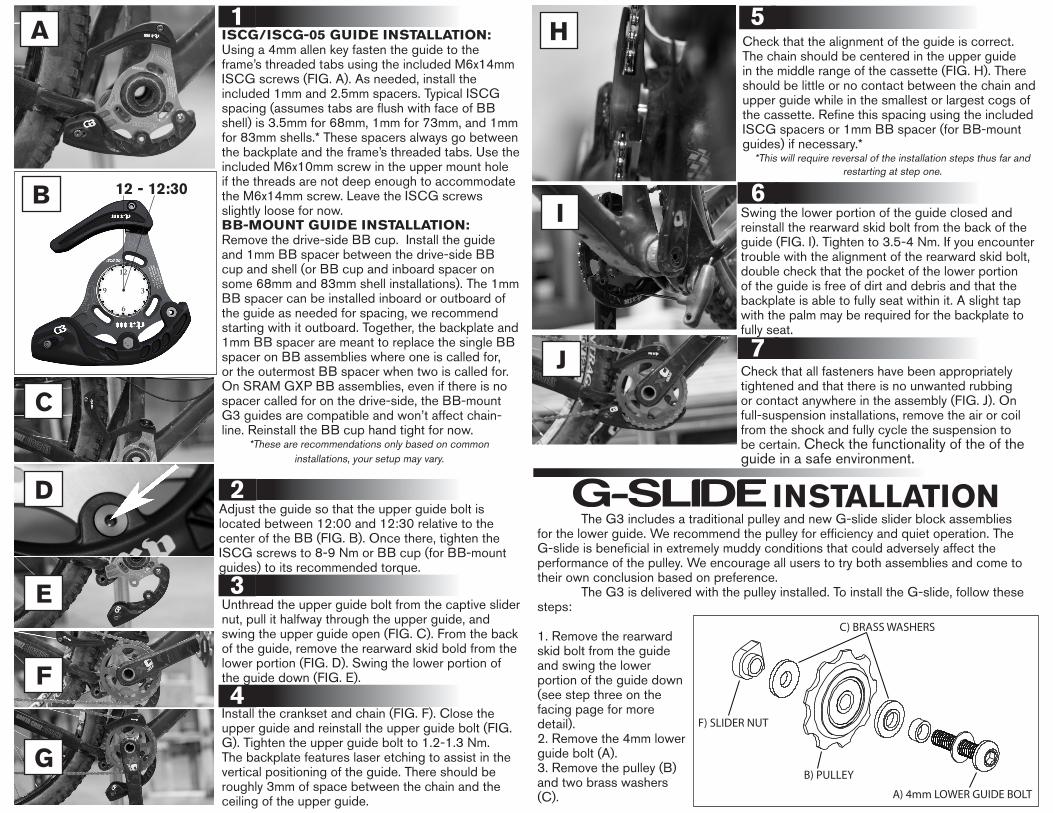
ISCG/ISCG-05 GUIDE INSTALLATION:Using a 4mm allen key fasten the guide to the frame’s threaded tabs using the included M6x14mm ISCG screws (FIG. A). As needed, install the included 1mm and 2.5mm spacers. Typical ISCG spacing (assumes tabs are flush with face of BB shell) is 3.5mm for 68mm, 1mm for 73mm, and 1mm for 83mm shells.* These spacers always go between the backplate and the frame’s threaded tabs. Use the included M6x10mm screw in the upper mount hole if the threads are not deep enough to accommodate the M6x14mm screw. Leave the ISCG screws slightly loose for now.BB-MOUNT GUIDE INSTALLATION:Remove the drive-side BB cup. Install the guide and 1mm BB spacer between the drive-side BB cup and shell (or BB cup and inboard spacer on some 68mm and 83mm shell installations). The 1mm BB spacer can be installed inboard or outboard of the guide as needed for spacing, we recommend starting with it outboard. Together, the backplate and 1mm BB spacer are meant to replace the single BB spacer on BB assemblies where one is called for, or the outermost BB spacer when two is called for. On SRAM GXP BB assemblies, even if there is no spacer called for on the drive-side, the BB-mount G3 guides are compatible and won’t affect chain-line. Reinstall the BB cup hand tight for now.
*These are recommendations only based on common installations, your setup may vary.
Unthread the upper guide bolt from the captive slider nut, pull it halfway through the upper guide, and swing the upper guide open (FIG. C). From the back of the guide, remove the rearward skid bold from the lower portion (FIG. D). Swing the lower portion of the guide down (FIG. E).
1
2
3
Install the crankset and chain (FIG. F). Close the upper guide and reinstall the upper guide bolt (FIG. G). Tighten the upper guide bolt to 1.2-1.3 Nm. The backplate features laser etching to assist in the vertical positioning of the guide. There should be roughly 3mm of space between the chain and the ceiling of the upper guide.
4
Swing the lower portion of the guide closed and reinstall the rearward skid bolt from the back of the guide (FIG. I). Tighten to 3.5-4 Nm. If you encounter trouble with the alignment of the rearward skid bolt, double check that the pocket of the lower portion of the guide is free of dirt and debris and that the backplate is able to fully seat within it. A slight tap with the palm may be required for the backplate to fully seat.
Check that all fasteners have been appropriately tightened and that there is no unwanted rubbing or contact anywhere in the assembly (FIG. J). On full-suspension installations, remove the air or coil from the shock and fully cycle the suspension to be certain. Check the functionality of the of the guide in a safe environment.
6
7
The G3 includes a traditional pulley and new G-slide slider block assemblies for the lower guide. We recommend the pulley for efficiency and quiet operation. The G-slide is beneficial in extremely muddy conditions that could adversely affect the performance of the pulley. We encourage all users to try both assemblies and come to their own conclusion based on preference. The G3 is delivered with the pulley installed. To install the G-slide, follow these steps:
A) 4mm LOWER GUIDE BOLT
C) BRASS WASHERS
B) PULLEY
F) SLIDER NUT
1. Remove the rearward skid bolt from the guide and swing the lower portion of the guide down (see step three on the facing page for more detail).2. Remove the 4mm lower guide bolt (A).3. Remove the pulley (B) and two brass washers (C).
INSTALLATION
Check that the alignment of the guide is correct. The chain should be centered in the upper guide in the middle range of the cassette (FIG. H). There should be little or no contact between the chain and upper guide while in the smallest or largest cogs of the cassette. Refine this spacing using the included ISCG spacers or 1mm BB spacer (for BB-mount guides) if necessary.*
*This will require reversal of the installation steps thus far and restarting at step one.
5
12 - 12:30
Adjust the guide so that the upper guide bolt is located between 12:00 and 12:30 relative to the center of the BB (FIG. B). Once there, tighten the ISCG screws to 8-9 Nm or BB cup (for BB-mount guides) to its recommended torque.
A
B
C
D
E
F
G
H
I
J