Embed Size (px)
Citation preview

D 5.3.2.1: Energy Storage Systems for the Use in Photo Voltaic Systems

Revision history Edition Date Status Editor V0.1 30.10.2011 Approval Raili Alanen V1.0 12.12.2011 Final Raili Alanen Pictures on the front page: Raili Alanen and European Batteries Oy.

D 5.3.2.1: Energy Storage Systems for the Use in Photo Voltaic Systems 3 (67)
Abstract Climate change and global warming are major drivers to decrease carbon emissions in power production. Photovoltaic power systems have on principle emission free power production and the photovoltaic power production is fast increasing all over the world. Photovoltaic technology is fast developing from both technology and economical point of view. Photovoltaic systems can be built without energy storages but energy storage integrated systems would give more techno-economic benefits for different stakeholders from small system owner to transmission system operator. Future higher penetration of renewable power and higher system performance needs (especially with Smart Grids) will make energy storages as an essential part of photovoltaic power productions systems. Also energy storage technology is fast developing mainly because of increased amount of electric vehicles. Main developing area is battery storage technology especially lithium-ion batteries. There are also some efforts to develop smaller compressed air storage technologies that would be suitable for the solar power systems that need longer-term storage capacity. Larger solar power systems need also efficient power electronics and advanced control methods to be able to optimise power production for different targets. In this study it is evaluated current and developing electrical energy storage technology, grid-connection systems and control functions suitable for different kind and sizes of photovoltaic systems.

D 5.3.2.1: Energy Storage Systems for the Use in Photo Voltaic Systems 4 (67)
Contents Revision history .................................................................................................................. 2 Abstract ............................................................................................................................... 3 Contents .............................................................................................................................. 4 1 Preface......................................................................................................................... 6 2 Introduction and goal .................................................................................................. 7 3 PV systems –features, requirements ........................................................................... 8
3.1 PV features in the Nordic area ............................................................................ 8 3.2 PV system types.................................................................................................. 9
4 Benefits of energy storages in PV systems ............................................................... 11 4.1 End-user benefits .............................................................................................. 11 4.2 Grid connected storage-PV-systems, requirements and services ..................... 13
5 Current energy storage technologies and R&D ........................................................ 14 5.1 Electric double-layer capacitors (EDLC).......................................................... 14 5.2 Flywheels .......................................................................................................... 15 5.3 Lead based batteries.......................................................................................... 17
5.3.1 Lead Acid batteries ................................................................................... 17 5.3.2 Lead Carbon batteries: PcB ...................................................................... 19 5.3.3 Lead Carbon batteries in grid-tied solar systems...................................... 19
5.4 Nickel-based batteries....................................................................................... 20 5.5 Lithium ion batteries ......................................................................................... 21 5.6 Sodium based batteries ..................................................................................... 25
5.6.1 NaS batteries ............................................................................................. 25 5.6.2 Sodium-metal chloride batteries – ZEBRA and Durathon batteries......... 29 5.6.3 ZnBr Batteries........................................................................................... 32 5.6.4 Vanadium Redox Batteries ....................................................................... 34
5.7 New types of developing storage techniques for PV systems .......................... 36 5.7.1 Aqueous Sodium ion battery..................................................................... 36 5.7.2 Fe-Cr Flow Battery ................................................................................... 37 5.7.3 New type of compressed air storage ......................................................... 38 5.7.4 New type of li-ion batteries....................................................................... 38
6 Comparison of different energy storage technologies .............................................. 39 7 Requirements for energy storages in solar power management ............................... 41 8 PV-system load/ grid integration types..................................................................... 42
8.1 Stand-alone PV-system types ........................................................................... 42 8.2 Grid-connected PV-system concepts without batteries .................................... 43 8.3 Basic grid-connected PV-system concepts with battery storages..................... 44
9 Photovoltaic inverters ............................................................................................... 46 10 PV-system basic control ....................................................................................... 49
10.1 PV-power control.............................................................................................. 49 10.1.1 Solar module I-V characteristics............................................................... 49

D 5.3.2.1: Energy Storage Systems for the Use in Photo Voltaic Systems 5 (67)
10.1.2 Maximum power point tracking (MPPT) techniques ............................... 49 10.2 PV-system storage control ................................................................................ 53
10.2.1 Stand alone PV battery control ................................................................. 53 10.2.2 MPPT control improvement by distributed energy storages .................... 53 10.2.3 Energy storages connected into PV-inverter DC-link .............................. 55
10.3 PV-storage system management communication types.................................... 59 11 Example of an installed large PV-system with storages....................................... 61 12 Conclusions........................................................................................................... 63 13 Abbreviations........................................................................................................ 64 14 References............................................................................................................. 66
D 5.3.2.1: Energy Storage Systems for the Use in Photo Voltaic Systems 6 (67)
1 Preface The work done for this report is part of Smart Grid and Energy Market programme (SGEM) of Cluster of Energy and Environment (CLEEN) financed by Finnish Funding Agency for Technology and Innovation, industrial partners, universities, and research institutes. Espoo 30.10.2011 Author: Raili Alanen

D 5.3.2.1: Energy Storage Systems for the Use in Photo Voltaic Systems 7 (67)
2 Introduction and goal Climate change and global warming are major drivers to decrease carbon emissions in power production. Photovoltaic power systems have on principle emission free power production and the photovoltaic power production is fast increasing all over the world. Photovoltaic technology is fast developing from both technology and economical point of view. Photovoltaic systems can be built without energy storages but energy storage integrated systems would give more techno-economic benefits for different stakeholders from small system owner to transmission system operator. Future higher penetration of renewable power and higher system performance needs (especially with Smart Grids) will make energy storages as an essential part of photovoltaic power productions systems. Also energy storage technology is fast developing mainly because of increased amount of electric vehicles. The goal of this study is to find out the requirements for energy storages and their control strategies in different solar power system applications and make a review of current and developing electrical energy storage technologies suitable for solar power systems.

D 5.3.2.1: Energy Storage Systems for the Use in Photo Voltaic Systems 8 (67)
3 PV systems –features, requirements
3.1 PV features in the Nordic area Photovoltaic energy is a form of highly stochastic variable (Figure 3-1) renewable energy. Solar PV technologies converse global horizontal irradiation (GHI) into electricity. Concentrating PV (CPV) technologies utilize beam (direct) normal radiation (DNI). Because CPV systems use direct radiation they need to be continuously tracked. The regions (like Middle East, North Africa and southern Europe) that have beam radiation greater than 2000 kWh/m2/year are regarded to be suitable for the use of CPV technologies. PV systems are suitable even in Northern Europe level. Northern PV systems can be provided with fixed tilt or single axis tracking. The power output of PV system depends on GHI, local weather condition such as temperature, wind velocity and clouds. Also impurities on the panel surface decrease the panels’ performance. PV panel performance is also depending on the module temperature.
(i) )1.3(3.4*528.1*028,0)(*943.0)(mod +−+= windspeedIrradianceCTCT ambule
oo
where irradiance is W/m2 and wind speed is m/s.[1]
09.0
9.20
11 7
:04:
00
09.0
9.20
11 8
:38:
00
09.0
9.20
11 1
0:12
:00
09.0
9.20
11 1
1:46
:00
09.0
9.20
11 1
3:20
:00
09.0
9.20
11 1
4:54
:00
09.0
9.20
11 1
6:28
:00
09.0
9.20
11 1
8:02
:00
09.0
9.20
11 1
9:36
:00
09.0
9.20
11 2
1:10
:00
09.0
9.20
11 2
2:44
:00
10.0
9.20
11 0
:18:
00
10.0
9.20
11 1
:52:
00
10.0
9.20
11 3
:26:
00
10.0
9.20
11 5
:00:
00
10.0
9.20
11 6
:34:
00
10.0
9.20
11 8
:08:
00
10.0
9.20
11 9
:42:
00
10.0
9.20
11 1
1:16
:00
10.0
9.20
11 1
2:50
:00
10.0
9.20
11 1
4:24
:00
10.0
9.20
11 1
5:58
:00
10.0
9.20
11 1
7:32
:00
10.0
9.20
11 1
9:06
:00
10.0
9.20
11 2
0:40
:00
10.0
9.20
11 2
2:14
:00
10.0
9.20
11 2
3:48
:00
11.0
9.20
11 1
:22:
00
11.0
9.20
11 2
:56:
00
11.0
9.20
11 4
:30:
00
11.0
9.20
11 6
:04:
00
11.0
9.20
11 7
:38:
00
11.0
9.20
11 9
:12:
00
11.0
9.20
11 1
0:46
:00
11.0
9.20
11 1
2:20
:00
11.0
9.20
11 1
3:54
:00
11.0
9.20
11 1
5:28
:00
11.0
9.20
11 1
7:02
:00
11.0
9.20
11 1
8:36
:00
Figure 3-1. Example of Photo Voltaic power hourly/daily variations of sunny days in the Helsinki area.
Also yearly insolation varies a lot in Nordic areas having 3 very low production months in the middle of winter from November to February (Figure 3-2).

D 5.3.2.1: Energy Storage Systems for the Use in Photo Voltaic Systems 9 (67)
Figure 3-2. Monthly averaged insolation incident on a horizontal surface kWh/m2/day in Helsinki area.
3.2 PV system types There are basically five types of PV systems (Table 3-1) depending on the application area and power level. [4][3]
Table 3-1. Photovoltaic system types.
No Type Application area Power Phase Connection type 1 Small
residential Customer site: private houses, summer cottages
<1 kW Typically single-phase
Off-grid, typically storage included
2 Residential Customer site: private houses
< 10 kW, typical 3 kW
Typically single-phase
Off-grid or grid-tied, without storage or storage-included
3 Small commercial
Customer site: public buildings, small industrial buildings, community common
10 kW – 50 kW
Three-phase
Grid-tied, without storage or storage-included
4 Large commercial
Customer site: industrial building area, community common, small PV power plants
50 kW – 100 kW
Three-phase
Grid-tied without storage or storage-included
5 Very large commercial
Large PV power plants
100 kW – megawatts
Three-phase
Grid-tied typically without storage

10 (67)
D 5.3.2.1: Energy Storage Systems for the Use in Photo Voltaic Systems Most PV-systems are grid-connected today (Figure 3-3). Large PV power plants can be also islanded but seldom photovoltaic is only power production system and PV systems are connected into the local power grid with other power production plans.
Figure 3-3. Cumulative installed grid-connected and off-grid PV power in IEA countries (IEA PVPS Programme, 2009).

D 5.3.2.1: Energy Storage Systems for the Use in Photo Voltaic Systems 11 (67)
4 Benefits of energy storages in PV systems PV system can be built without energy storages but an energy storage integrated PV-system can provide wider financial, operational and environmental benefits [4] to the owner/end-user, distributed system provider, transmission system provider and society.
Table 4-1. Benefits of storage integrated PV-systems.
No Type Application area Benefits 1 Small
residential Customer site: private houses, summer cottages
Back-up power, time-shift for own peak power need, electricity for summer cottages, save energy bill (if hour or minute-based billing system)
2 Residential Customer site: private houses
Back-up power, save PV power at peak power time, save energy bill, load shifting, smart grid interface, in future savings by the energy market actions
3 Small commercial
Customer site: public buildings, small industrial buildings, community common
Ride-through during cloud cover, distributed generation, peak shaving, emission reduction, short-term spinning reserve, savings by the energy market actions, smart grid managements
4 Large commercial
Customer site: industrial building area, community common, small PV power plants
Savings by the energy market actions, power quality and UPS, microgrid generation, islanding, smart grid managements
5 Very large commercial
Large PV power plants
Savings by the energy market actions, islanding, carbon reductions, smart grid managements
4.1 End-user benefits For end-user point of the energy storage in PV-system can e.g.
• Time-shift PV-power for own peak-time consumption (Figure 4-1 and Figure 4-2) • Provide back-up power for electricity interruptions • Time-shift PV-power for energy market during high price time

D 5.3.2.1: Energy Storage Systems for the Use in Photo Voltaic Systems 12 (67)
Figure 4-1. Storages can time-shift PV-power for own peak-time consumption (Annual average daily profile). [25]
Figure 4-2. Storages can time-shift PV-power for own peak-time consumption (Annual average daily profile, 10% with highest PV yield). [25]

D 5.3.2.1: Energy Storage Systems for the Use in Photo Voltaic Systems 13 (67)
4.2 Grid connected storage-PV-systems, requirements and services
When PV-system is grid connected it has to follow recommendations and requirements and standards defined for the grid-connected power production. These regulations and grid codes include standards (IEEE1547, IEC62116, UL 1471, VDE-0126-1-1, Spanish grid code O.P.12.2, future ENTSO-E etc.) for voltage quality, power quality, anti-islanding (IEC62116, IEEE1547) and response to other abnormal grid conditions. Large grid-connected PV-power plants are in-line with wind power plants connected to either distribution or transmission levels. [24] Large grid connected PV-system can support grid performance but only when sufficient PV-power is available. Energy storages connected to the system make power available more continuously (depends on the size of storage) and can provide services for different smart grid participants. Large over 10 MW PV-power plant can provide services for transmission grid operators (TSO). Smaller PV-plants connected to distribution grid could provide services for distribution system operator (DSO), private system operators (PSO) and third parties (TP) such as energy market participants. [2] Possible grid services: Power quality control:
• Power quality improvement (TSO, DSO), • Reactive power control (TSO, PSO), • Balancing services e.g. frequency control (TSO, TP)
Distribution reliability: • Voltage control (TSO, DSO), • Reduction grid losses (DSO), • Reduction capacity utilization (DSO) • Black start (DSO), • Islanding (DSO), • Uninterruptible power supply (PSO)
Energy management: • Local energy management (PSO) • Energy for energy market actions (TP) • Backup energy (PSO) Table 4-2. Rough energy storage sizing requirements for grid services.
Service Energy storage power Storage time Power quality control 0.01 x Pload 0-1 s Distribution reliability 1 * Pload 1 s – 15 min Energy management 0.1 x Pload 15 min – 24 h

14 (67)
D 5.3.2.1: Energy Storage Systems for the Use in Photo Voltaic Systems
5 Current energy storage technologies and R&D Electrical energy can be stored directly (capacitors) or indirectly via energy conversion: in the form of kinetic energy (flywheels), chemical energy (batteries) or potential energy (pumped hydro and compressed air). On principle all available energy storage technologies are usable with PV-systems. It depends on PV-system type and size as well as the system use. Most used types are different kind of electrochemical batteries. In the following chapter it is described typical storage technologies usable with photovoltaic systems. Large long-term storage technologies such as pumped hydro and compressed air storages that are technically power plants are not handled in this document.
5.1 Electric double-layer capacitors (EDLC) Technology Electrochemical capacitors with relatively high energy density are often called super- and ultracapacitors. Supercapacitor or ultracapacitor is an electro-chemical double layer capacitor. The capacitor is formed electrochemically between electrolyte and electrode (Figure 5-1). The voltage of the supercapacitor is near linear and drops evenly from full voltage to zero volts.
Figure 5-1. Capacitor type schematics. [Source: www.ultracapacitors.org]
Technical Properties Supercapacitors can operate in the full range 0% to 100% SOC but practical operation area is 25% to 100%. Super-capacitor charge-discharge efficiency is around 98%. Cell voltage is typically 1.2 to 1.5 VDC. Charge time is about 10 seconds. For example, an SAFT supercapacitor module (583 F, 15 V, 400 A) can be charged from zero voltage

D 5.3.2.1: Energy Storage Systems for the Use in Photo Voltaic Systems 15 (67) (zero of charge) to the maximum voltage in 22 s at a constant current of 400 A [29]. The initial charge is rapid but the topping charge takes more time. When fully charged they stop accepting more charge. Control system and Interface Stringed capacitors need balancing circuits to be able to charge all stringed capacitors properly passing fully charged capacitors. Supercapacitor bank can be connected to the DC-bus by bi-directional DC-DC-converter and to the AC-bus by AC-DC-converter. Manufactures, Commercial Products and Solutions Main supercapacitor manufacturers are in USA and in Japan (Table 5-1).
Table 5-1. An example of supercapacitor manufacturers and product sizes.
5.2 Flywheels Flywheel energy storage (FES) system can store energy in the form of kinetic energy of a rotating rotor. On charging, the flywheel is accelerated, and on power generation, it is slowed. The kinetic energy stored in a rotating mass is:
E=0.5ωJ2 (4.2) Where ω is the angular velocity and J is the moment of inertia that is a function of the mass and shape of the flywheel. High-energy flywheels have typically heavy steel wheel and lower speed when high rotor of the power and high-speed (20,000 to 50,000 rpm) flywheels are made of high strength carbon fibre-composite filaments. High-speed flywheels have usually a vacuum enclosure

s 16 (67)
D 5.3.2.1: Energy Storage Systems for the Use in Photo Voltaic System
and magnetic bearings (Figure 5-2). The motor/generator is usually a high-speed permanent magnet machine and integrated with the rotor.
Figure 5-2. Flywheel [Source: Beacon Power]
Technical Properties Flywheels are available in different sizes. Output energy of flywheel depends on the type for example energy density of the steel flywheel is about 0.045 MW/h/m3, composite flywheel 0.323 MW/h/m3 and advanced ‘nano’ flywheel even 0.531 MW/h/m3. The maximum output power is dependant upon the duration required. This is illustrated in figure (Figure 4�3) below. Increased power, duration and/or redundancy can be achieved by adding units in parallel. Flywheels have ability to buffer rapid power fluctuations due to clouds in PV systems.
Figure 5-3. Figure of the performance chart. KWb refers to kilowatts on DC bus of the UPS system. [Source: Pentadyne]

s for the Use in Photo Voltaic Systems 17 (67)
D 5.3.2.1: Energy Storage System 5.3 Lead based batteries
5.3.1 Lead Acid batteries Most used battery type is a lead acid (LA) battery. Flooded wet cell (FLA) batteries are widely used in cars. Sealed lead acid (SLA) batteries can be valve regulated (VRLA) (Figure 5-4) and they can include glass matt (AGM) or gel (GEL) technology.
Figure 5-4. Schematic of an open and valve regulated lead acid battery. [14]
The SLA is commonly used when high power is required, weight is not a limiting factor and low cost is critical. Especially SLI (starting, lighting, ignition) batteries are the most low cost batteries used typically as a car starting battery. They can have high current for a short time but they have low energy capacity and are not suitable for a deep discharge. Because cells in GEL –batteries are sealed and cannot be re-filled with electrolyte, controlling the rate of charge is very important or the battery will be ruined in a short order. Gel cells use slightly lower charging voltages than flooded cells and thus the set-points for charging equipment have to be adjusted. Absorbed Glass Mat (AGM) batteries are the latest step in the evolution of lead-acid batteries. Instead of using a gel, an AGM uses a fiberglass like separator to hold the electrolyte tied in place. Since they are also sealed, charging has to be controlled carefully or they can be ruined in short order. Gel cells and AGMs basically require no maintenance. Lead acid lifetime is depending on temperature because every 15 °C increases over 25 °C halving their lifetime. Energy density is 50 Wh/l, efficiency 80–90 %, lifetime 3-12 years, cyclic lifetime 50–2000 (7000) cycles, temperature area – 25 °C - +60 °C.
Lead acid battery charging methods Lead acid batteries are typically charged in three stages using voltage-based method.
• Stage 1: Constant current charge. Battery is charged to 70 % of its full charge level
• Stage 2: Topping charging with lower charging current to full charge. • Stage 3: Float charge compensates self-discharge, maintains the full charge
preventing sulfation.

s 18 (67)
D 5.3.2.1: Energy Storage Systems for the Use in Photo Voltaic System
Lead acid battery charge time depends on battery type and size being 10-12 hours with sealed acid batteries up to 36-48 hours of large stationary batteries. Insufficient charging of flooded lead acid battery may cause stratification. Overcharging can cause gassing that is explosive. To prevent gassing the charging current should be reduced when the gassing threshold is reached [13].
Figure 5-5. Charge stages of a lead-acid battery. [Source: BatteryUniversity]
Lead acid battery manufacturers There are various amounts of LA battery types manufactured for solar systems like Sun Xtender AGM batteries (Figure 5-6). Also Exide (XIDE), Enersys (ENS), Johnson Controls, Optima Batteries and C&D Technologies (CHP).

D 5.3.2.1: Energy Storage System s 19 (67)
s for the Use in Photo Voltaic System
Figure 5-6. AGM battery. [Source: SunXtender]
Advanced lead acid technology can be a new possibility for lead batteries in PV applications. This new improved performance technology is based on carbon electrodes.
5.3.2 Lead Carbon batteries: PbC Lead carbon batteries are a latest development result of lead based batteries. Select carbons added into the negative electrode can increase battery life remarkable (10x). One or both electrodes of lead carbon battery can be made from activated carbon as in supercapacitors. The electrode can be made of carbon graphite foam that is covered with lead.
If the negative electrode is made from carbon the chemical reaction is:
)arg(22)()( 2)2(
66 eddischeHHnCHnC xx
xx −
+−+−−+− ++⇔ (4.3)
As a result of larger surface (1500 m2/g) the reaction rate is faster, discharge speed is faster and the weight and size of the battery is smaller (half) than lead acid battery. Also the capacity in cold circumstances is bigger and corrosion is smaller.
5.3.3 Lead Carbon batteries in grid-tied solar systems First U.S. fully grid-tied solar energy storage (250 kW, 1 MWh) started to work online near Albuquerque on September 2011 including 1280 advanced GS Battery ECO- R nano carbon lead-acid batteries. The storage system includes 8 battery containers including 160 batteries in each container. The PureWave SMS storage management system (S&C Electric company) smoothes the output from solar panels, mitigating potential variations brought on by resource intermittency, to ensure continued grid reliability and stability. Axion Power has also developed PbC based technology and their mobile storage PowerCubeTM can deliver up to 1 MW of power for 30 minutes or 100 KW of power for 10 hours.

s 20 (67)
D 5.3.2.1: Energy Storage Systems for the Use in Photo Voltaic System
5.4 Nickel-based batteries Nickel Cadmium (NiCd) batteries have a good load characteristics; they are simple to use and economically priced. NiCd batteries can be designed for different speed of charge. Nickel metal hydride (NiMH) provides 30% more capacity over a standard NiCd. The positive electrode of the NiMH battery is nickel hydroxide. The active material for the negative electrode in the NiMH battery is actually hydrogen and the hydrogen ions (protons) are stored in the metal hydride structure that also serves as an electrode. The NiMH is affected by memory to a lesser extent than the NiCd. Periodic exercise cycles need to be done less often. NiCd batteries can be designed for different speed of charge. They need maintenance charge because of self-discharge that is about 5% during 24h after a battery is charged. Constant current charging is recommended for sealed NiCd cells. A figure (Figure 5-7) shows a typical NiCd battery charge curve. Battery system need cell based temperature control to prevent over discharge and control of shallow discharge to prevent voltage depression.
Figure 5-7. Typical charge curve of the NiCd battery. [Source: QuestBatteries]
Nickel metal hydride (NiMH) provides 30% more capacity over a standard NiCd. The positive electrode of the NiMH battery is nickel hydroxide. The active material for the negative electrode in the NiMH battery is actually hydrogen and the hydrogen ions (protons) are stored in the metal hydride structure that also serves as an electrode. The NiMH is affected by memory to a lesser extent than the NiCd. Periodic exercise cycles need to be done less often. Because of low toxic metals content, the NiMH is labelled "environmentally friendly".

s 21 (67)
D 5.3.2.1: Energy Storage Systems for the Use in Photo Voltaic System
5.5 Lithium ion batteries Technology Lithium-ion batteries are one of the most promising battery types for Smart Grid applications. Lithium is very reactive material and translates into have high energy density batteries. Typical material for the anode is graphite. The cathode is generally one of three materials: a layered oxide, such as lithium cobalt oxide, one based on a polyanion, such as lithium iron phosphate (Li-FePO4, LFP), or a spinel, such as lithium manganese oxide (LiMnO2) or titanium disulfide (TiS2) (Figure 5-8). Depending on the choice of material for the anode, cathode, and electrolyte the voltage, capacity, life, and safety of a lithium ion battery can change remarkable. Liquid electrolytes in Li-ion batteries consist of solid lithium-salt electrolytes, such as LiPF6, LiBF4, or LiClO4, and organic solvents, such as ether.
Figure 5-8. An example of lithium-ion battery function. [Source: Saft]
Technical Properties Lithium-ion batteries offer energy densities of 100–150 Wh/kg with charge/discharge efficiencies of 90–100%. [30] Cyclic lifetime is long, depending on a battery type from 3000 cycles to 16000 full cycles and even 250000 partial cycles. Lithium batteries have no memory effect. Lithium batteries are very sensitive to over voltage and need also temperature and current control as well as deep discharge control and a battery balancing system for larger series connected systems. Lithium-ion batteries should be stored in low temperature (0-°25 C) rather at 40% than at 100% charge to decrease ageing process. Most lithium-ion battery electrolytes freeze at approximately –40°C. New lithium battery system solutions include also intelligent control system and are packed in the standard lead acid Battery Council International (BCI) format sizes. Lithium batteries are seen as future electric car batteries because of lightweight and high energy. Lithium batteries are
22 (67)
D 5.3.2.1: Energy Storage Systems for the Use in Photo Voltaic Systems
very promising technology also for PV systems but technology and products are still under development for longer lifetime, better safety and efficiency and lower price. Control system and Interface Large Li-ion battery system requires two-level battery management system. Each cell should be protected against over/under voltage and overtemperature. Stringed cells are protected against overvoltage in charging by cell balancing system that can be thermistor or electronics based circuit. The battery string should be protected against over- and undervoltage, overcurrent and overtemperature and reverse polarity. Advanced management system includes also communication bus connections and local database that includes information of lowest and highest voltage and temperature, highest current used, number of cycles done and messages and alarms. Main battery management unit takes care of the communication with battery chargers and can include charge and discharge control relays to ensure safety of charging.
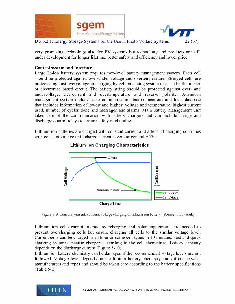
Lithium-ion batteries are charged with constant current and after that charging continues with constant voltage until charge current is zero or generally 7%.
Figure 5-9. Constant current, constant voltage charging of lithium-ion battery. [Source: mpoweruk]
Lithium ion cells cannot tolerate overcharging and balancing circuits are needed to prevent overcharging cells but ensure charging all cells to the similar voltage level. Current cells can be charged in an hour or some cell types in 10 minutes. Fast and quick charging requires specific chargers according to the cell chemistries. Battery capacity depends on the discharge current (Figure 5-10). Lithium ion battery chemistry can be damaged if the recommended voltage levels are not followed. Voltage level depends on the lithium battery chemistry and differs between manufacturers and types and should be taken care according to the battery specifications (Table 5-2).

s 23 (67)
D 5.3.2.1: Energy Storage Systems for the Use in Photo Voltaic System
Table 5-2. Examples of the li-ion battery voltage levels.
Battery type Battery chemistry
Nominal voltage /V
Maximum charge voltage (/V
Discharge cut-off voltage /V
Li-cobalt LiCoO2 3.20-3.60 3.60-4.20 2.80 Li-phosphate LiFePO4 3.2-3.30 3.60-3.65 2.0-2.5 Li-manganese LiMn2O4 3.7-3.80 4.20 2.75
Figure 5-10. Capacity and voltage vs. discharge current. [Source: http://www.europeanbatteries.com/solutions/cells]
Cyclic life depends on lithium-ion battery type and depth of discharge (DoD) (Figure 5-11 and Figure 5-12).

24 (67)
D 5.3.2.1: Energy Storage Systems for the Use in Photo Voltaic Systems
Figure 5-11. Capacity of a lithium-phosphate battery as a function of charge-discharge cycles. [Source: A123 Systems]
Figure 5-12. Cyclic life vs. Depth of Discharge of Lithium Titanate battery. [Source: Altairnano]

D 5.3.2.1: Energy Storage Systems for the Use in Photo Voltaic Systems 25 (67)
5.6 Sodium based batteries
5.6.1 NaS batteries Technology NAS battery consists of sulfur at positive electrode, sodium at negative electrode as active materials, and Beta alumina of sodium ion conductive ceramic, which separates both electrodes (Figure 5-13). This hermetically sealed battery is operated under the condition where the active materials at both electrodes are liquid and its electrolyte is solid.
Figure 5-13. Sodium sulfur cell and principle of NaS battery. [Source: NGK Insulators]
Approximately 2V is generated between the positive and the negative electrodes at about 300°C. If a load is connected to terminals, electric power is discharged through the load. During the discharge, sodium ions converted from sodium in a negative electrode pass through solid electrolyte then reach to sulfur in positive electrode. The electrons finally flow to outside circuits. The electric power is generated by such current flow. With the progress of the discharge, sodium polysulfide is formed in positive electrode; on the contrary, sodium in negative electrode will decrease by consumption. During the charge, the electric power supplied from outside form sodium in negative electrode and sulfur in positive electrode by following the reverse process of the discharge. Because of this, the energy is stored in the battery.

s 26 (67)
D 5.3.2.1: Energy Storage Systems for the Use in Photo Voltaic System
Technical Properties NAS battery has 151-kWh/m3 energy density, approximately 2V voltage at about 260 to 360°C working temperature. NaS battery has 15-year service life and high cycle life (2500 cycles at 100% DOD – 4500 at 90% – 6500 at 65%). A sample commercial battery pack capacity is 50 kW in 64 V or 128 V and includes 320 cells. Typical System capacity is 2000 kW and includes 50 kW Module x 40 Units. Commercial product specifications are given in Table 5-3 and Table 5-4.
Table 5-3. NaS single cell specification. [Source NGK]
Table 5-4. Characteristics of NaS 50 KW modules. [Source NGK]

s 27 (67)
D 5.3.2.1: Energy Storage Systems for the Use in Photo Voltaic System
Figure 5-14. NaS 50 KW module construction. [Source NGK]
NaS battery can give max. 5xPn pulsepower when discharged in 30 sec. (Figure 5-15).
Figure 5-15. NaS pulse (or PQ factor) vs. discharge duration. [15]
Control system and Interface NaS battery system can be connected to grid with AC-DC converter (Figure 5-16).

s for the Use in Photo Voltaic Systems 28 (67)
D 5.3.2.1: Energy Storage System
Figure 5-16. Battery storage grid connection system. [Source: ABB]
Life Cycle Aspects One module alone provides 2500 full charge/discharge cycles. This value is equal to 15 years in operation. (At 100% DOD - depth of discharge), or 4,500 cycles (at 80% DOD). Economical Aspects Costs per unit for NAS battery is about 1300-1500 $/kW, 200$/kWh. Manufactures, Commercial Products and Solutions A Japanese company NGK Insulators LTD has been only NaS battery manufacturer with production capacity 150 MW/year in 2010. NGK insulators has installed 302 MW across 215 systems worldwide. There are close to 279 MW of NaS batteries on the grid in Japan and 9 MW of NaS in USA. Within last two year NKG has announced two large order 150 MW of EDF and 300MW to United Arab Emirates. Latest challenge is to ensure fire safety of the battery systems. POSCO in Korea and Eagle Picher Technologies have also informed to start developing large capacity NaS batteries. Application in PV systems NAS battery with solar PV generations makes possible maximum use of PV generation resources without producing CO2. NaS system can stabilize/smooth (Figure 5-17 and Figure 5-18) intermittent PV power. For ancillary services NAS-PV system can provide fast acting reserves (spinning reserve), standby reserves, black start and frequency regulation control without the emissions of conventional generating plant. NaS system can also support islanded sections of the grid.

D 5.3.2.1: Energy Storage Systems for the Use in Photo Voltaic Systems 29 (67)
Figure 5-17. NaS system stabilizating intermittent renewable energy. [Source NGK]
Figure 5-18. 1.5 MW NaS alongside 5 MW Solar PV Array in Japan. [Source NGK]
5.6.2 Sodium-metal chloride batteries – ZEBRA and Durathon batteries
ZEBRA battery ZEBRA batteries are based on sodium nickel chloride technology. Sodium/nickel chloride based batteries are produced on a commercial scale in Switzerland by MES-DEA (now FIAMM SoNick). The battery has to be maintained at an internal operating temperature of between 270˚C and 350˚C for efficient operation. In Figure 5-19 it is shown a principle of the ZEBRA battery chemistry.

30 (67)
D 5.3.2.1: Energy Storage Systems for the Use in Photo Voltaic Systems
Figure 5-19. Principle Zebra battery. [16]
ZEBRA batteries are produced as 24 V−1000 V, 2 kWh−50 kWh systems. Batteries are maintenance free. Weight is around 40% of lead acid battery weight. ZEBRA Battery technology has proven calendar life of more that 10 years and cycle life of 1000 nameplate cycles dependent on operating parameters. [16] Zebra® is a complete self-contained off-shelf battery system, and not a building sub-block. Fitted with battery Management Interface controlling battery operation, Zebra® battery is easy to install and use. The BMI, with integrated main circuit breakers is the “brain of the battery system and it provides: - Temperature control - S.O.C. measurement - Nameplate cycles counter - Charger control - Measurement of the battery insulation resistance - Supervision of current and voltage current limits - Life-Data-Memory like a “black box” - CAN-BUS communication with the system controller. To increase total energy storage on board, BMI allows up to 16 Zebra® batteries to work together in parallel. Initial warm up time after cold storage is about 24 hours. Therefore it is best if the battery is used continuously. Once at working temperature, the battery performance is not affected by ambient temperature which can be -40°C...+50°C.

D 5.3.2.1: Energy Storage Systems for the Use in Photo Voltaic Systems 31 (67)
Figure 5-20. ZEBRA-battery and battery block diagram. [Source: FZ Sonic]
On February 1st, 2010 FIAMM and MES-DEA constituted a new company FZ Sonick SA that continues producing ZEBRA salt batteries. Durathon Battery GE Transportation has launched molten salt battery by the name Durathon in 2010. GE’s sodium-metal-halide battery consists of a nickel chloride cathode, a beta alumina separator and a liquid sodium anode. During charging, Cl is extracted from NaCl and combined with Ni to form NiCl2 (Figure 5-21). The Na ions are then transported through the beta alumina to the anode reservoir. Discharge is the reverse of this process. Because sodium ions move easily across the beta alumina but electrons cannot, there are no side reactions, and therefore no self-discharge. All of the materials are housed in a hermetically sealed steel case, which becomes the individual cell. Cells are then contained in a thermally insulated battery module (Figure 5-22). An integral battery management system is installed on all battery modules and controls charge/discharge, monitors battery parameters, provides battery protection, and passes information to the outside world through common Modbus protocol.
Figure 5-21. Durathon battery cell. [Source: GE Transportation]

32 (67)
D 5.3.2.1: Energy Storage Systems for the Use in Photo Voltaic Systems
Figure 5-22. Durathon battery module. [Source: GE Transportation]
5.6.3 ZnBr Batteries
echnology was developed by Exxon in the early 1970’s. ZnBr battery consists of a
TZnBr battery zinc negative electrode and a bromide positive electrode separated by a micro porous separator. An aqueous solution of zinc/bromide is circulated through the two compartments of the cell from two separate reservoirs.

33 (67)
D 5.3.2.1: Energy Storage Systems for the Use in Photo Voltaic Systems
Figure 5-23. Principle of ZnBr battery storage. Source: http://electricity.ehclients.com
The electrodes do not take part in the reactions but serve as substrates for the reactions. During the charge cycle metallic zinc is plated from the electrolyte solution onto the negative electrode surfaces in the cell stacks. Bromide is then converted to Bromine at the positive electrode surface of the cell stack and is immediately stored as a safe, chemically complex organic phase in the electrolyte tank. When the battery discharges, the metallic zinc plated on the negative electrode dissolves in the electrolyte and is available to be plated again at the next charge cycle. In the fully discharged state the ZnBr battery can be left indefinitely. Technical properties of ZnBr batteries:
Specific energy 34.4−54 Wh/kg (124−190J/g) Energy density 75−85 Wh/kg Round trip efficiency (AC to AC) 70−75 % Time durability >20 years Cycle durability > 2000 cycles even >>10000 cycles Nominal cell voltage 1.8 V (typically falls to 1.3 V at an operating current density of 100 mA cm-2) 100% depth of discharge capability on a daily basis.

s 34 (67)
D 5.3.2.1: Energy Storage Systems for the Use in Photo Voltaic System
5.6.4 Vanadium Redox Batteries Technology Vanadium redox flow battery is based the use of solubility of vanadium in four different oxidation states in sulphuric acid. The overall reactions at both electrodes during charging/discharging of the VRB are:
At the negative electrode: V E0=-0.26V (4.1) −++ +↔ eVedisch
ec
3arg
arg
2
OHVOHeedisch
ech 22
arg
arg2 2 +↔++ ++−+
At the positive electrode: VO E0=1.0V (4.2)
The principle of the VRB is shown in more detail in (Figure 5-24). It consists of two electrolyte tanks, containing active vanadium species in different oxidation states.
Figure 5-24. Principle of VRB. Source: Sumimoto Electric.
Output power and energy storage capacity are independent. Energy storage capacity is determined by the concentration and volume of the electrolyte. The output power depends on the number of flow cells (stacks) and the surface area of the electrodes. The electrolytes can be fed through the stack of cell in parallel or in series (Figure 5-25) that decrease bypass currents. VRB operates at normal temperature.

s 35 (67)
D 5.3.2.1: Energy Storage Systems for the Use in Photo Voltaic System
Figure 5-25. Series flow with bipolar electrodes. Source: Cellenium.
Technical properties of VRB Specific energy 10–20 Wh/kg (36–72 J/g) Energy density 15–25 Wh/L (54–65 kJ/l) Charge/discharge efficiency 75-80% Time durability 10–20 years Cycle durability >10000 cycles Nominal cell voltage 1.15–1.55 V
Typical charge/discharge curves for a 100-cell VRB-stack are presented in Figure 5-26.
Figure 5-26. Typical charge and discharge curves for a 100-cell VRB stack. [17]

36 (67)
D 5.3.2.1: Energy Storage Systems for the Use in Photo Voltaic Systems
5.7 New types of developing storage techniques for PV systems
5.7.1 Aqueous Sodium ion battery New aqueous sodium ion battery type is based on activated carbon anode, NaMnO2 cathode and aqueous sodium ion based electrolyte. Battery has long cycle life and high efficiency (Table 5-5). [5][6]
Table 5-5. Aqueous sodium ion battery performance features. [Source Aquionenergy [5]]
Battery modules can be stacked and connected in series/parallel as needed. >100 V strings are in use currently, > 1000 V strings planned for fall. Minima or no battery management system required. Demonstration packs are already available for customer evaluation and production is planned to start late 2011 or 2012.
Figure 5-27. Aqueous Sodium ion battery system including 10 stacked 8 batteries, 15 V modules. [5]

s 37 (67)
D 5.3.2.1: Energy Storage Systems for the Use in Photo Voltaic System
5.7.2 Fe-Cr Flow Battery Fe-Cr flow battery (Figure 5-28) is developed to improve flow-battery performance and cost issues. Battery system supports space saving installation (Figure 5-28).
Figure 5-28. Fe-Cr Flow Battery principle. Source: Enervault. [7]
Fe-Cr flow battery (250kW, 1 MWh) for PV smoothing and peak shifting is demonstrated in Almond Grove 300 kW PV power plant. [6]
Figure 5-29. Fe-Cr Flow Battery system. Source: Enervault. [7]

D 5.3.2.1: Energy Storage Systems for the Use in Photo Voltaic Systems 38 (67)
5.7.3 New type of compressed air storage The Thayer School of Engineering at Dartmouth College developed a modernized and more efficient CAES plant design in 2007. Spin-off company SustainX continues to develop a commercial solution to support renewables. ICAES (isothermal compressed-air energy storage), uses electrical energy to compress air near-isothermally, stores it aboveground in commercial gas storage facilities, and expands it near-isothermally to generate electricity using no fossil fuels. The systems has higher isothermal efficiency (94.9%) compared an adiabatic technique (54%). New products (e.g. 1 MW system) is planned to bring to market in 2012.
Figure 5-30. Isothermal compressed-air energy storage using hydraulics.[6] [8]
5.7.4 New type of li-ion batteries At the moment there are a lot of funding allocated for rechargeable li-ion battery development. The goal is improved performance e.g. cyclic life and safety, lower weight, faster charging ability and lower cost. For example Lawrence Berkeley Laboratory is making and testing new type of li-ion battery that uses thin films of polymer as the electrolyte and high-density, lightweight electrodes. Start-up company SEEO Inc. continues developing the battery that has high energy density, is entirely solid state, with no flammable or volatile components.

s 39 (67)
D 5.3.2.1: Energy Storage Systems for the Use in Photo Voltaic System
6 Comparison of different energy storage technologies
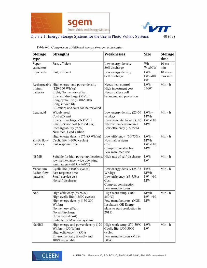
Application area, needed technical and economical requirements are the key features for the selection of suitable energy storage type. In the following table (Table 6-1) it is compared weaknesses and strengths of different storage technologies. Energy storage cost depends on the place and case and investment cost of the ES system includes cost of power electronics and grid interconnection costs. The total cost depends on e.g. the storage type and size and includes investment costs, installation cost, infrastructure cost, design, permissions etc. cost, maintenance and use cost and finally renovation and recycling cost. In the following picture it is presented combination of available cost information for different storage types.
Figure 6-1. Cost of energy storages as $/kW.
D 5.3.2.1: Energy Storage Systems for the Use in Photo Voltaic Systems 40 (67)
Table 6-1. Comparison of different energy storage technologies
Storage type
Strengths Weaknesses Size Storage time
Super-capacitors
Fast, efficient Low energy density Self discharge
Wh W-x00W
10 ms – 1 min
Flywheels
Fast, efficient Low energy density Self discharge
kWh kW–x00 kW
10 ms – tens min
Rechargeable lithium batteries
High energy- and power density (120-160 Wh/kg) Light, No memory effect Low self discharge (5%/m) Long cyclic life (3000-5000) Long service life Li- oxides and salts can be recycled
Needs heat control High investment cost Needs battery cell balancing and protection
kWh – 1MW
Min - h
Lead acid
Widely used Cost efficient Low selfdischarge (2-3%/m) Small service cost (closed LA) Rechargeability (90%) New tech. Lead-carbon.
Low energy density (25-50 Wh/kg) Environmental hazard (Lb) Narrow temperature area Low efficiency (75-85%)
kWh – MWh kW ->10 MW
Min - h
Zn-Br flow batteries
High energy density (75-85 Wh/kg) Cyclic life (>2000 cycles) Fast response time
Low efficiency (70-75%) No small systems Cost Complex construction Few manufacturers
kWh – MWh kW ->10 MW
Min - h
Ni MH Suitable for high power applications, low maintenance, wide operating temp. range (-20ºC -+60ºC)
High rate of self-discharge kWh kW
Min - h
Vanadium Redox flow batteries
Cyclic life (>10000 cycles) Fast response time Small service cost No self-discharge
Low energy density (25-35 Wh/kg) Low efficiency (65-75%) Cost Complex construction Few manufacturers
kWh – MWh kW ->10 MW
Min - h
NaS High efficiency (89-92%) High cyclic life (~2500 cycles) High energy density (150-200 Wh/kg) No memory effect, No selfdischarge (Low capital cost) Suitable for MW size systems
High work temp. (300-350°C) Few manufacturers (NGK Insulators, GE Energy plans to start production in 2011)
MWh kW ->10 MW
Min - h
NaNiCl High energy and power density (120 Wh/kg, >150 W/kg) High efficiency (> 85%) Environmentally friendly and 100% recyclable
High work temp. 270-50°C Cyclic life 1500-3000 cycles Few manufacturers (MES-DEA)
kWh kW
Min - h

D 5.3.2.1: Energy Storage Systems for the Use in Photo Voltaic Systems 41 (67)
7 Requirements for energy storages in solar power management
Solar power is intermittent with fast high changes and long interruptions by nights and during winter time. In the following table (Table 7-1) it is presented requirements and suitable energy storage technologies for each type of solar power application.
Table 7-1. Requirements for energy storages in solar power management.
Time scale Target Driving force Storage requirements
Energy storage type
Very fast (ms)
Power quality control, smoothing
Power quality standards, regulations
Very fast, very high cycle life, power demand varies
Electrostatic/ electro-chemical (super) capacitors, SMES
Fast (s)
Power quality control, smoothing
Power quality standards, regulations
Very fast, very high cycle life, power demand varies
Electro-chemical (super) capacitors, SMES, flywheels
Medium fast (min)
Power quality control, smoothing
Power quality standards, regulations
Fast, high cycle life, power demand varies
Super-capacitors, flywheels, batteries
Slow (h)
Power smoothing, management of peak power, breaks etc.
Power production reliability, economical aspects
High power, high energy, proper cycle life
Batteries, flow batteries, (small CAES in future) (large CAES and pumped hydro for large global systems)
Very slow (d, m)
Energy management
Power production reliability, economical aspects
High energy and power
Batteries, flow batteries, small CAES in future, (large CAES and pumped hydro for large global systems)
CAES (Compressed Air Energy Storage), SMES (Superconducting Magnetic Energy Storage)

D 5.3.2.1: Energy Storage System s 42 (67)
s for the Use in Photo Voltaic System
8 PV-system load/ grid integration types PV-system can be either stand alone or grid-connected system without or with energy storages. A standalone PV-system can be a simple battery charging DC-system. More advanced PV-systems can be connected to the load, grid and storages with four basic types 2) Stand alone PV-system connected to the DC load (Figure 8-1)
a) Without batteries b) With batteries
3) Stand alone PV-system connected to the AC-load a) Without batteries b) With batteries
4) Basic Grid-tied system (no local storages) connected to AC-grid (Figure 8-3) 5) Grid-tied system with energy storages connected to AC-grid (Figure 8-6)
a) with unidirectional inverter b) with bidirectional inverter
PV-system and storages can also be a part of local AC-microgrid that can have connection to the public AC-grid or not.
8.1 Stand-alone PV-system types Grid-tied PV-system can be connected to the low-voltage AC-grid directly by the inverter or to medium voltage grid with inverter and transformer.
Figure 8-1. Stand alone PV-system connected to the DC-load a) Without batteries, b) With batteries.

D 5.3.2.1: Energy Storage Systems for the Use in Photo Voltaic Systems 43 (67)
Figure 8-2. Stand alone PV-system connected to the AC-load a) Without batteries, b) With batteries.
8.2 Grid-connected PV-system concepts without batteries PV-system without batteries includes DC-DC converter part and DC-AC inverting part (Figure 8-3).
Figure 8-3. Pure Grid-tied system (no local storages) connected to AC-grid.
Actually there are defined and implemented several topologies for larger grid connected PV-systems. Topologies are studied e.g. by Chaaban M. A. [19] in 2011 and some common topologies shown in the following figures a)−f) of the Figure 8-4. Simplest and low cost configuration is one central inverter configuration but it has no optimal MPPT (MPP can be different of each PV-panel string) and it has low reliability because of one inverter. Central inverter is typical for 10-250 kW three-phase systems. Topologies b)-f) are more reliable and efficient but more costly. String multi inverter system is used for 1.5-5 kW, typical residential, applications. Most recent topology a module-inverter or micro-inverter topology f) has many advantages such as reduction of losses due of partial

D 5.3.2.1: Energy Storage Systems for the Use in Photo Voltaic Systems 44 (67) shading, better monitoring module failure and flexibility of array design but it is suitable only low power applications (≤500 kW) and has relatively high cost.
Figure 8-4. Grid-connected PV-system topologies. [19]
There are two types of transformer-based topologies: PV-array on the low frequency side or on the high-frequency side (Figure 8-5). [24]
Figure 8-5. Transformer-connected PV-arrays. [24]
8.3 Basic grid-connected PV-system concepts with battery storages
Grid-connected PV-systems can be connected to the grid by unidirectional inverter when batteries are load only by PV-power or bidirectional inverter that allows battery system loaded also from the grid.

D 5.3.2.1: Energy Storage Systems for the Use in Photo Voltaic Systems 45 (67)
Figure 8-6. Grid-tied system with energy storages connected to AC-grid a) with unidirectional inverter, b) with bidirectional inverter.

D 5.3.2.1: Energy Storage Systems for the Use in Photo Voltaic Systems 46 (67)
9 Photovoltaic inverters
Typically PV-system voltage is too low for string inverters and boost circuit is needed to raise voltage in low power circumstances.
Figure 9-1. Basic PV-system – inverter configurations.
High power 3-phase PV-plants are typically connected to the medium voltage grid with transformer. In some countries it is needed galvanic isolation between PV-plant and grid. In some cases a low-frequency-high frequency transformer is used. Transformerless topologies have higher efficiency and the grid regulations are changing to allow them. [24]
Three-phase inverter topologies. There are two main types of three-phase inverter topologies used in Europe: Voltage-source inverters (VSI) (Figure 9-2) and current source inverters (CSI) (Figure 9-3). A latest type presented is Z-Source Inverter (ZSI) (Figure 9-4) [20]. An example of the latest proposed concepts is a new concept of a Resonant Pole Inverter (RPI) (Figure 9-5) [21].

47 (67)
D 5.3.2.1: Energy Storage Systems for the Use in Photo Voltaic Systems
Figure 9-2. 2-level VSI with boost converter. [20]
Figure 9-3. CSI with buck converter. [20]
Figure 9-4. ZSI with voltage-source bridge. [20]

48 (67)
D 5.3.2.1: Energy Storage Systems for the Use in Photo Voltaic Systems
Figure 9-5. Resonant pole inverter new concept. [21]
Table 9-1. Comparison of different three-phase PV-inverter types. [20] [21]
Inverter type Advantages Disadvantages VSI Standard IGBT-Modules/drivers
can be used Potentially low common-mode currents at PV-generator Simple control, pulse width modulation (PWM)
Additional Boost Converter required Many passive components Not short-circuit proof Switching losses EMC-behaviour
CSI Single-stage concept, low part count Very suitable for Power MOSFETs due to inactive body diodes No AC current sensors needed PWM control
Series diodes cause additional barrier losses Capacitive output filter draws reactive power No standard power modules/drivers applicable Not open-circuit proof, Switching losses
ZSI Single stage concept, low semiconductor part count Wide input voltage range Standard IGBT power modules can be used Buck and Boost function PWM control Short-circuit and open-circuit proof
Input blocking diode Additional passive components No standard gate drivers can be used Switching losses
RPI new Lower DC-link capacitance Low current stress Smaller magnetics
Pulsating DC-link voltage Dynamic DC/DC converter required

s 49 (67)
D 5.3.2.1: Energy Storage Systems for the Use in Photo Voltaic System
10 PV-system basic control
10.1 PV-power control Advanced PV power control takes care of solar module characteristics to find the maximum power production point and achieve thus higher system efficiency.
10.1.1 Solar module I-V characteristics A PV-panel has a certain voltage and current under specific conditions. Voltage and current dependence can be presented as current-voltage (I-V) characteristics under certain sunlight and temperature conditions. Solar module characteristics have an essential role in inverter and storage control system design. The I-V characteristics of a solar module is
rshp
Ss
asatgsP I
NIRN
VAKTqV
IINNI −⎪⎭
⎪⎬⎫
−⎟⎟⎠
⎞⎜⎜⎝
⎛+
⎩⎨⎧
= 1exp 00
00
000 IVP
(5.1)
where I0 is output current, V0 is output voltage, Ig is generated current under a given insolation, Isat is the reverse saturation current, q is the charge of electron, K is the Boltzmann’s constant, A is the ideality factor, Ta is the temperature (K), Np is the number of cell in parallel, Rs is the internal series resistance and Irsh is the current due to intrinsic shunt resistance of the solar module. [9][10] The solar module output power (P0) is = (5.2)
10.1.2 Maximum power point tracking (MPPT) techniques Maximum Power Point (MPP) is achieved in a certain voltage and current point (Figure 10-1). If the load is directly connected to PV-panel the operating point depends on the load and can be lower than the MPP. To ensure that load’s power requirements are fully covered the PV-panels are typically oversized. To avoid system oversizing and achieve best performance it can be used a switchmode converter to perform a maximum power point tracking (MPPT) technique to continuously deliver the highest possible power to the load. [12]

D 5.3.2.1: Energy Storage System s 50 (67)
s for the Use in Photo Voltaic System
Figure 10-1. Typical current, voltage and power curve for a 12 PV-module. Source: samplexsolar
MPPT is not known a priori and depends in a non-linear way on • The irradiance and • Temperature.
In multi-panel systems working conditions varies also because of: [22] • Discrepancies in module parameter values caused by manufacturing tolerances, • Different module ageing effects, • Different orientations of modules • Clouds • Other shadowing effects like buildings, trees, power lines etc.
There is defined various methods for MPPT e.g. perturbation and observation (P&O) method (Figure 10-2), which moves the operating point toward the maximum power point periodically increasing or decreasing the array voltage (see flowchart in the Figure 10-3). The incremental conduction method (IncCond) tracks the maximum power points by comparing the incremental and instantaneous conductance of the solar array, MPPT control using microprocessor with two-loop control and digital signal processor (DSP) based control that uses P&O method with self-tuning function. According to the comparative studies of Hohm & Ropp [12] P&O method, already by far the most commonly used algorithm in commercial converters, has the potential to be very competitive when properly optimised for the given hardware. [12] [10][11]

D 5.3.2.1: Energy Storage Systems for the Use in Photo Voltaic Systems 51 (67)
Figure 10-2. P&O method to find the MPP. [13]
Figure 10-3. P&O algorithm flowchart. [18]

s 52 (67)
D 5.3.2.1: Energy Storage Systems for the Use in Photo Voltaic System
Figure 10-4. IncCond method to find MPP. [13]
Table 10-1. MPPT control algorithms [10][11] [12]
Algorithm Basic principle Advantages and disadvantages Voltage feedback method
MPPT is considered as a constant value and voltage adjusted according to voltage reference
Easy realize but don’t reach MPP when temperature varies
Measure method (pilot cell)
Extra solar cell is used as a reference
Best performance in MPPT but costly needing measurements and extra cell.
Linear approach Output is controlled keeping it on the linear P-I curve
Easy to realize and good performance, large temperature changes and components aging decrease accuracy
Incremental conductance method (IncCond)
Output voltage is adjusted according to the current-voltage ratio and conductance increment.
Small power loss but high requirements for sensors
Perturbation and observation method (P&O)
Moves the operating point toward the maximum power point periodically increasing or decreasing the array voltage
Commonly used. Works well when insolation not vary quickly with time, oscillates around MPP, fails to quickly track the MPP
Three points comparing method
Similar to P&O but uses three point to make a decision
Less power loss but rather complex structure and poor real time performance
Model-based algorithms
Max. powerpoint voltage is calculated according to light incident and temperature measurements.
Not practical because the values of the each cell parameters are not known with certainty.

s 53 (67)
D 5.3.2.1: Energy Storage Systems for the Use in Photo Voltaic System 10.2 PV-system storage control Storage control functions in PV-systems include basic storage type-specific control functions described in the chapter number 4 and other techno-economical requirements of the technical interconnection system or economical point of view of the use. Economical point of includes
10.2.1 Stand alone PV battery control The simplest stand-alone PV-battery system is a self-regulation system where PV-cell is directly connected to the battery (typically to a lead-acid battery). The charge-controlled stand-alone PV battery system with load and battery can be controlled using typical battery voltage set points defined in the following figure (Figure 10-5). The voltage regulation point disconnects battery from the PV array. At the voltage value ARV battery can be reconnected to the PV array. In the LVD point battery is disconnected from the PV array to avoid overdischarge. In the LRV point load can be reconnected to the battery. [13] The basic battery charging is performed with battery specific way e.g. lead acid battery is charged in three stages defined in the chapter 4.3.1.
Figure 10-5. Charge controller set points. [13]
10.2.2 MPPT control improvement by distributed energy storages
Large PV-systems include PV panels connected in series strings. The string current is equal to the lowest current generated of the lowest performance panel and the system is

s 54 (67)
D 5.3.2.1: Energy Storage Systems for the Use in Photo Voltaic System not working in the maximum working point. This is typically corrected using a bypass diode connected in parallel with each module, which decrease efficiency. When system includes several PV-strings there can exist several maximum points (Figure 10-6) and the conventional inverters fails to find the real whole system maximum working point and can start to work in the local maximum point decreasing significantly the system efficiency. To correct that there are presented several distributed active MPPT functions. However, these functions are rather complex. Also proposed multi- or multistage-inverter systems to correct the problem are high costly. [22] [23]
Figure 10-6. Different maximum working points in shaded or non-shaded parts of the PV-plant. [23]
Carbone R. [22] has proposed a new technique to overcome the problem and improve PV-plant efficiency; passive MPPT using distributed battery energy storages. In a passive MPPT system a battery storage is connected parallel of the each PV-string and central inverter is used to connect the PV-system to the grid. The nominal voltage of the battery sub-system has to be chosen very close to the MPP voltage of the related PV sub-field that is approximately equal to 75-80% of the PV sub-field open circuit voltage. The battery storage can naturally catch the MPP of each sub-field and whole system losses are smaller. [22]

D 5.3.2.1: Energy Storage Systems for the Use in Photo Voltaic Systems 55 (67)
Figure 10-7. Passive MPPT with batteries. [22]
10.2.3 Energy storages connected into PV-inverter DC-link
Energy storage capacitor Energy storage capacitor can be used e.g. between the boost-converter and inverter to balance the instantaneous power delivered to the grid.
Figure 10-8. Energy storage capacitor between PV-converter and inverter to balance instantaneous power delivered to the grid. [26]

D 5.3.2.1: Energy Storage Systems for the Use in Photo Voltaic Systems 56 (67)
tPtPPtpP acacacacac ωω 2cos)2cos1()( =−−=− (6.1)
Figure 10-9. Capacitor charging – discharging rules.[26]
The ripple voltage is
ωCD
acDC CV
PV =Δ (6.2)
Lithium-ion batteries Battery systems can also be connected into PV-inverter DC-link (Figure 10-10).
Figure 10-10. Lithium-ion batteries connected into the PV-inverter DC-link.

D 5.3.2.1: Energy Storage Systems for the Use in Photo Voltaic Systems 57 (67) Dual storage system Dual energy storage system (e.g. battery bank and supercapacitors) with PV-power plant can be connected (Figure 10-11) either a) into the DC-link of the PV-power inverter or directly to the AC-grid with own inverter. The combined system will provide an ability to smooth both fast and slow changes of the PV-power output, batteries (1500 Ah, 500 V) are used to smooth high power peaks and valleys and ultracapacitors (1700 F, 700 V) control faster power changes (Figure 10-12). The system can also control current grid harmonics (Figure 10-13) and reactive power (Figure 10-14).
Figure 10-11. Battery-ultracapacitor dual-storage system connected a) into the DC-link of the PV-inverter, b) into AC-grid with own inverter.

D 5.3.2.1: Energy Storage Systems for the Use in Photo Voltaic Systems 58 (67)
Figure 10-12. Operating areas of the batteries and ultracapacitors of a dual-storage system in the case of 1 MW power plant output power smoothing.
Figure 10-13. Harmonic current reduction with dual-storage system and active filtering.[28]

s 59 (67)
D 5.3.2.1: Energy Storage Systems for the Use in Photo Voltaic System
Figure 10-14. Reactive power compensation with dual-storage system. [28]
10.3 PV-storage system management communication types PV-system energy storage combination can be managed many different ways e.g. [3]
a) Single autonomous systems (PV-inverter-storage) can be controlled directly by separate controller including grid connect/disconnect commands and charge/discharge commands e.g. according to time of the day or direct pricing signal.
b) Interactive management of several autonomous systems that are loosely-coupled e.g. with SCADA system and can participate group work or not depending e.g. the state of storages. Communication could use e.g. IEC 61850 standard. The group system could provide local reactive power or voltage control services.
c) One-way broadcasting or multicasting to specific types/sizes/regions of typically small PV inverters e.g. because of demand of grid control services. Grid measurements provide feedback of successful actions or feed-back is received from common SCADA-system but not directly for separate PV system. This type of management could provide services for DSO.

D 5.3.2.1: Energy Storage Systems for the Use in Photo Voltaic Systems 60 (67)
Figure 10-15. PV-ES system management functions as a grid-tied distributed energy system (DER). [3]

D 5.3.2.1: Energy Storage Systems for the Use in Photo Voltaic Systems 61 (67)
11 Example of an installed large PV-system with storages
An example of the large PV-plant with energy storages is installed in Wakkanai City in Japan. The plant includes crystalline PV-panel capacity of 5 MW together and 1.5 MW/11.8 MWh NaS battery and 1.5 MW/25 kWh double-layer capacitor pack. Batteries and PV-plant are connected to 6.6 kV grid via transformers and the whole system in connected to 33 kV via transformer. The system includes also solar radiation forecast.
Figure 11-1. An example of the large PV-plant (5 MW) with centralized multistorages in Wakkanai City, Japan.
Today, utilities must manage energy reserves to minimize higher costs associated with maintaining an oversupply of energy and the risk of blackouts from an undersupply or sudden loss of energy. This requires a real-time balance of supply and demand of energy into the grid not currently being met by coal and natural gas energy sources. These problems can be resolved with the proper mix of energy storage options that can accomplish four critical things: [Source: AzRISE]

D 5.3.2.1: Energy Storage Systems for the Use in Photo Voltaic Systems 62 (67)
1. Provide back-up power for an unexpected drop in sunshine or wind.
2. Provide electricity at night and in bad or calm weather.
3. Smooth out variations in renewable energy production on very short time scales.
4. Readjust seasonal variations in energy production to better match demand load. (For solar, move excess energy produced in the spring to the periods of high-energy demand in summer and winter.)

D 5.3.2.1: Energy Storage Systems for the Use in Photo Voltaic Systems 63 (67)
12 Conclusions PV system can be built without energy storages but an energy storage integrated PV-system can provide wider financial, operational and environmental benefits to the owner/end-user, distributed system provider, transmission system provider and society. Smart grid management requirements and wider penetration levels of intermittent PV-power makes energy storages necessary to be able to get full benefit of produced energy as well as to be able provide sufficient smart grid management. Requirement for energy storage features varies according to size and applications of PV-systems. Available energy storage technologies can in principle fulfil the needs of the different PV-application types from smoothing of fast peak-type changes (cloud effects) by supercapacitors (or by flywheels or batteries) to longer period power shifting with different kind of batteries. Energy storages can be installed directly to PV-panels as integrated microstorages or in different sizes and combinations into PV-system DC-part or directly to the AC-grid by own inverter. Large PV-power plants should in future (and in some cases today) fulfil the same grid connection requirements and ability to support grid functions than e.g. wind power plants. When energy pricing will in future support smaller distributed power provider, will also smaller PV-power producer get more benefits with their storage-integrated PV-power systems by selling energy produced by PV-peak power time at higher price during a high power consumption time. Energy storage grid and/or system connection should also be efficient and cost effective and the need of advanced and cost-effective power electronics and control systems is increasing with larger PV-plants implementation. For future PV-systems energy storages should be more efficient, have longer life-time and lower cost and maintenance-free. High energy density is important in PV-systems and longer storage time would be essential especially in Nordic countries. Safety is very important in end-user applications and high recyclability is essential for future systems. Low or rather zero carbon oxide release in the storage manufacturing phase makes produced energy from RES charged storages environmentally friendly.

D 5.3.2.1: Energy Storage Systems for the Use in Photo Voltaic Systems 64 (67)
13 Abbreviations AC Alternate Current AS Ancillary services BCI Battery Council International BMS Battery Management System BOP Balance Of Plant CAES Compressed Air Energy Storage Cl Chlorine CN Capacity in Ah of a battery discharged at a rate of C/N, where C is the nominal
capacity of the battery and N is the time of discharge CP total specific cost bases on power [€/kW] CSP Concentrated Solar Power DC Direct Current DG Distributed Generation DOD Depth of Discharge DoD Depth of Discharge DOE Department of Electricity (US) DSM Demand Side Management EM Specific Energy [Wh/kg] [kWh/t], or gravimetric energy density ES Energy for surface area [kWh/m2] ESA Electric Storage Association (US) ESS Energy Storage System EU European Union EV Energy density [Wh/l],[kWh/m3], or volumetric energy density EVs Electric Vehicles FACTS Flexible Alternating Current Transmission System FESS Flywheel energy storage system GE General Electric GTO Gate Turn-off GW Gigawatt IEA International Energy Agency IEEE Institute of Electrical and Electronics Engineers IGBT Insulated Gate IGBT Insulated Gate Bypolar Transistor IGCT Integrated Gate-Commutated Thyristor ISO Independent System Operator LiBF4 Lithium Tetrafluoroborate LiClO4 Lithium Chlorite Li-FePO4 Lithium Iron Phosphate LiMnO2 Lithium Manganese Oxide LiPF6 Lithium Hexafluorophosphate

D 5.3.2.1: Energy Storage Systems for the Use in Photo Voltaic Systems 65 (67)
LiTiO Lithium Titanate Oxide LS Lifetime in Service LT Technological lifetime MW Megawatt NaCl Sodium Chlorine NaS Sodium Sulphur NERC North American Electric Reliability Corporation NiCl2 Nickel Chloride NiCd Nickel Cadmium NiMH Nickel Metal Hydride Nmax Cyclability, maximum number of cycles that the storage is able to perform PbA Lead Acid battery PCS Power Conversion System or Power Conditioning System PHES Pumped Hydroelectric Storage System PHEV Plug in Electric Vehicle PHS Pumped Hydro Storage PV Photovoltaics R&D Research and Development RE Renewable Energy SCADA Supervisory Control And Data Acquisition SLI Starting Lighting and Ignition SMES Superconductive Magnetic Energy Storage SOC State of Charge T&D Transmission and Distribution TOU Time of Use TSO Transmission System Operator VAR Voltage Ampere Reactive VLA Vented lead acid VRB Vanadium Redox Battery VRLA Valve Regulated Lead Acid ZnBr Zinc/Bromine

D 5.3.2.1: Energy Storage Systems for the Use in Photo Voltaic Systems 66 (67)
14 References [1]. Harathi Nanda, Ganapathisubbu. “A STUDY OF CPV POTENTIAL IN INDIA”.
ISES 2011. [2]. Braun, M., Stetz T., Büdenbender K. “Integration of Photovoltaic in distribution
systems”. Electric Cars and integration of Renewable Energy at the 2020 horizon 10. – 12. March 2010, Lyngby – DTU, Denmark.
[3]. Specification for PV & Storage Inverter Interactions using IEC 61850 Object Models and Capabilities. Frances Cleveland. May 2010.
[4]. Dan Ton, Georgianne H. Peek, Charles Hanley, John Boyes. “Solar Energy Grid Integration Systems –Energy Storage (SEGIS-ES)”. Program Concept Paper, May 2008.
[5]. J. Whitacre, S. Pearson, T. Wiley. “Low Cost, Aqueous Electrolyte Sodium Ion Energy Storage”. ESA Electricity Storage Association, 21st Annual Meeting. June 6-9, 2011.
[6]. I. Gyuk. “Progress in Electrical Energy Storage”. IEA Paris, 02-15-11. [7]. C. R., Horne. “EnerVault, Company Introduction and Renewable Energy
Applications”. EPRI Renewable Energy Council, April 6, 2011. [8]. I. Gyuk. Electrical Energy Storage – Maintaining the Momentum. CESA 03-05-
11. [9]. Tomonobu Senjyu, Manoj Datta, Atsushi Yona, Toshihisa Funabashi, and Chul-
Hwan Kim. “PV Output Power Fluctuations Smoothing and Optimum Capacity of Energy Storage System for PV Power Generator”.
[10]. C. Hua, J. Lin, and C. Shen, “Implementation of a DSP controlled photovoltaic system with peak power tracking,” IEEE Trans. Ind. Electron., vol. 45, no. 1, pp. 99-107, Feb. 1998.
[11]. Tianxiao Huang, Bin Wang, Bo Jiang, Xinzhou Dong and Zhiqian Bo. “A novel control scheme of photovoltaic power plant in islanding operation”.
[12]. Hohm, D.P. and Ropp, M.E. “Comparative Study of Maximum Power Point Tracking Algorithms”. PROGRESS IN PHOTOVOLTAICS: RESEARCH AND APPLICATIONS. Prog. Photovolt: Res. Appl. 2003; 11:47–62 (DOI: 10.1002/pip.459).
[13]. Glavin, M. and Hurlay, W.G. “Battery management system for solar energy applications”.
[14]. Sauer, D. U. and Kowal, J. “Detailed cost Calculations for stationary battery storage systems”. Second International Renewable Energy Storage Conference (IRES II), Bonn, 19.-21.11.2007. Electrochemical Energy Conversion and Storage Systems Group Institute for Power Electronics and Electrical Drives (ISEA), RWTH Aachen University.
[15]. Bito, A. Overview of the Sodium-Sulfur (NAS) Battery for the IEEE Stationary Battery Committee. June 15, 2005.

D 5.3.2.1: Energy Storage Systems for the Use in Photo Voltaic Systems 67 (67)
[16]. Galloway, R.C.;Dustmann, C.-H. ZEBRA Battery - Material Cost. Availability and Recycling. EVS-20, Nov. 15 – 19, 2003 Long Beach, CA.
[17]. Blackaby, N. VRB technology comes to the fore. May 1, 2002. [18]. Das, S. P. “Converters and Inverters for PV system”. 2011. [19]. Chaaban, M.A. “Adaptive photovoltaic configurations for decreasing the
electrical mismatching losses. 2011. [20]. Bülo, T., Sahan, B., Nöding, C., Zacharias P. “Comparison of Three-Phase
Inverter Topologies for Grid-Connected Photovoltaic Systems”. 22nd European Photovoltaic Solar Energy Conference and Exhibition, 3 - 7 September 2007, Milan, Italy.
[21]. De Donker, R.W. “Power converter for PV-systems”. ECPE-Seminar. 2006.
[22]. Carbone, R. “Energy Storage in Grid-Connected Photovoltaic Plants”. [23]. Shimizu,T.; Hashimoto, O.; Kimura, G. (2003). “A Novel High-
Performance Utility- Interactive Photovoltaic Inverter System”. IEEE Transactions on Power Electronics, Vol.18, 2003, N. 2.
[24]. Teodorescu, R., Rodriquez, P., Liserre, M. “Power Electronics for PV Integration”. ISIE 2010.
[25]. Braun, M., Büdenbender, K., Barth, H. “Grid-friendly Local Consumption of PV Energy”. 5th International Renewable Energy Storage Conference, Berlin, 24 November 2010.
[26]. ECEN 2060. “Power Electronics and Control in Grid-connected PV systems.
[27]. Huff, G. Sandia National Laboratories.“Clean Tech & Solar panel Electricity Storage. NYC Solar Summit. 2009.
[28]. Alanen R., Saari P.. “Ultracapacitors and Batteries in Wind Power Systems Control and Operation”. Electrical Energy Storage Applications and Technologies, EESAT 2005, San Francisco, USA
[29]. Thounthong, P.; Raël, S.; Davat, B. Analysis of Supercapacitor as Second Source Based on Fuel Cell Power Generation. IEEE Transactions on energy conversion, vol. 24, no. 1, March 2009.
[30]. Chen H., Cong T.N., Yang W., Tan C., Li Y., Ding Y., 2009, “Progress in electrical energy storage system: A critical review”, Progress in Natural Science 19: 291-312