Embed Size (px)
Citation preview

CYLINDER SURFACE MOUNTCYLINDER LED LUMINAIRE CY / CP / CS SERIES
CY1, CY2 & CY3 adjustable Cylinders may be wall mounted in Dry / Damp locations only. Pendant and Stem /Drop Kit Cylinders accommodate flat or sloped ceiling conditions. Adjustable Wallwash CY2/3-AW: recommended spacing is 36” (914mm) on center with 36” (914mm) setback from wall plane with 30° tilt.Wallwash Unibody CY2/3-WW: recommended spacing is 48” (1213mm) on center with 36” (914mm) setback from wall plane.CY1/2/3-JBMP:Specified to mount flush with minimalist transition to standard j-box installed behind substrate (section D.1, page 2). CY1/2/3-SMK:Includes concealer plate to conceal mounting hardware between fixture and j-box for existing installations (section D.2, page 3).CY1/2/3-CMJB:Lucifer designed ceiling mount j-box for 1/2” and 3/4” direct conduit feed and provides minimalist transition from Cylinder to j-box (section D.3, page 4).
MOUNTING
This product must be installed in accordance with applicable electrical and installation codes by a person familiar with the construction and operation of the product and the hazards involved. “CAUTION– RISK OF FIRE”
I N S T A L L A T I O N
Before beginning any CYLINDER installation, disconnect electrical power at main switch or circuit breaker.
To reduce the risk of fire, electric shock, and potential damage to recessed housing assembly when electrical power is re-connected, DO NOT ATTEMPT TO CONNECT the following on branch circuit serving recessed downlight assembly:
CAUTION
•Motors •Power tools •Extension cords•Appliances or similar electronics
A.
Fixtures to be mounted in conditions where ambient temperatures do not exceed 40°C.
Ensure AC input voltage is protected against surges & load shifts prior to power supply input.
SAFETY INSTRUCTIONSB.Read installation instructions completely before attempting installation.
Failure to follow instructions may result in improper installation and void warranty.
Contact Lucifer Lighting Company with any questions or concerns before beginning any installation.
Ensure qualified electrician will perform all electrical procedures.
Disconnect electrical power circuit before attempting to install Cylinder, or if adding to or changing configuration Cylinder assembly.
CAUTION: When fixture is on for long periods the Cylinder surface will be hot. Take care when making adjustments.
1.
2.
3.
4.
5.
6.
1
Surface mounted Cylinder with dimmable LED module and optional integral driver. CY1 has standard 42° tilt; CY2 has standard 70° tilt; CY3 has standard 60° tilt. CY1, CY2 & CY3 adjustable Cylinders have tooless 357° rotation and optional 90° tilt with precision friction lock. Fixed Unibody and Stem Cylinders also available. Pendant Cylinders feature field-cuttable cable (section E, page 5).
DESCRIPTIONC.
D.
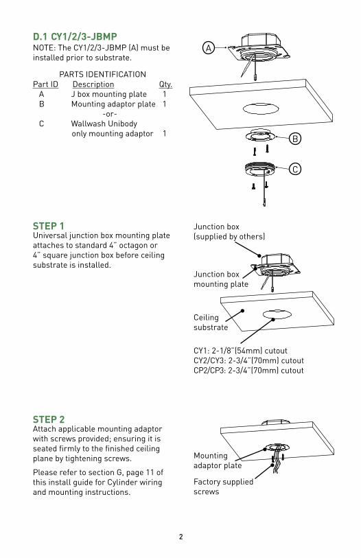
Universal junction box mounting plate attaches to standard 4” octagon or 4” square junction box before ceiling substrate is installed.
STEP 1
CY1/2/3-JBMP NOTE: The CY1/2/3-JBMP (A) must beinstalled prior to substrate.
Junction box(supplied by others)
Junction box mounting plate
Ceiling substrate
A
B
PARTS IDENTIFICATIONPart ID Description Qty. A J box mounting plate 1 B Mounting adaptor plate 1 -or- C Wallwash Unibody only mounting adaptor 1
CY1: 2-1/8”(54mm) cutoutCY2/CY3: 2-3/4”(70mm) cutoutCP2/CP3: 2-3/4”(70mm) cutout
D.1
Attach applicable mounting adaptor with screws provided; ensuring it is seated firmly to the finished ceiling plane by tightening screws.
Please refer to section G, page 11 of this install guide for Cylinder wiring and mounting instructions.
STEP 2
Factory suppliedscrews
2
C
Mountingadaptor plate
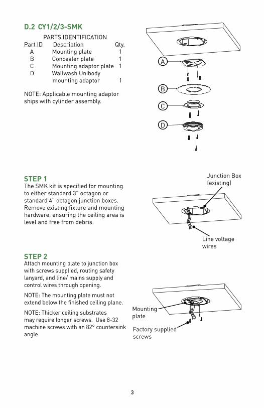
NOTE: Applicable mounting adaptor ships with cylinder assembly.
CY1/2/3-SMK
A
C
B
D
The SMK kit is specified for mounting to either standard 3” octagon or standard 4” octagon junction boxes. Remove existing fixture and mounting hardware, ensuring the ceiling area is level and free from debris.
STEP 1 Junction Box(existing)
Line voltage wires
D.2PARTS IDENTIFICATION
Part ID Description Qty. A Mounting plate 1 B Concealer plate 1 C Mounting adaptor plate 1 D Wallwash Unibody mounting adaptor 1
Attach mounting plate to junction box with screws supplied, routing safety lanyard, and line/ mains supply and control wires through opening.
NOTE: The mounting plate must not extend below the finished ceiling plane.
NOTE: Thicker ceiling substrates may require longer screws. Use 8-32 machine screws with an 82° countersink angle.
STEP 2
3
Mounting plate
Factory suppliedscrews
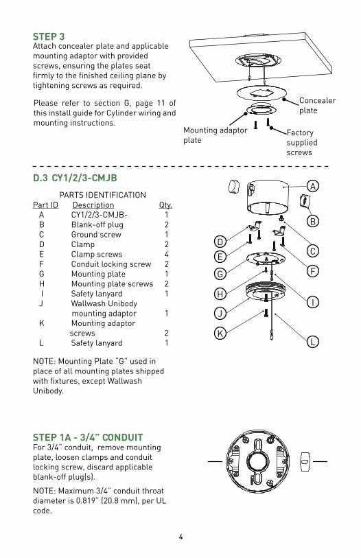
Attach concealer plate and applicable mounting adaptor with provided screws, ensuring the plates seat firmly to the finished ceiling plane by tightening screws as required.
STEP 3
Please refer to section G, page 11 of this install guide for Cylinder wiring and mounting instructions.
CY1/2/3-CMJB
NOTE: Mounting Plate “G” used in place of all mounting plates shipped with fixtures, except Wallwash Unibody.
D.3
PARTS IDENTIFICATIONPart ID Description Qty. A CY1/2/3-CMJB- 1 B Blank-off plug 2 C Ground screw 1 D Clamp 2 E Clamp screws 4 F Conduit locking screw 2 G Mounting plate 1 H Mounting plate screws 2 I Safety lanyard 1 J Wallwash Unibody mounting adaptor 1 K Mounting adaptor screws 2 L Safety lanyard 1
4
A
B
CD
E
G
HI
For 3/4” conduit, remove mounting plate, loosen clamps and conduit locking screw, discard applicable blank-off plug(s).
NOTE: Maximum 3/4” conduit throat diameter is 0.819” (20.8 mm), per UL code.
STEP 1A - 3/4” CONDUIT
F
Concealer plate
Mounting adaptor plate
Factory supplied screws
J
KL
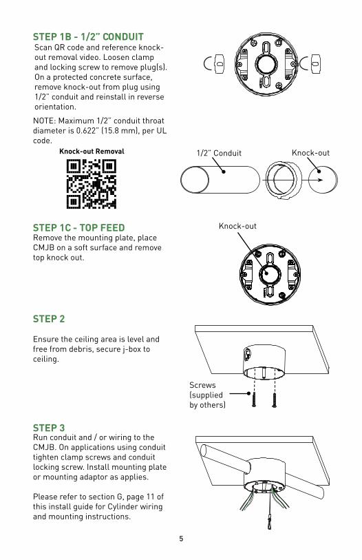
Ensure the ceiling area is level and free from debris, secure j-box to ceiling.
STEP 2
Screws (supplied by others)
Remove the mounting plate, place CMJB on a soft surface and remove top knock out.
STEP 1C - TOP FEED Knock-out
5
Run conduit and / or wiring to the CMJB. On applications using conduit tighten clamp screws and conduit locking screw. Install mounting plate or mounting adaptor as applies.
Please refer to section G, page 11 of this install guide for Cylinder wiring and mounting instructions.
STEP 3
STEP 1B - 1/2” CONDUIT Scan QR code and reference knock-out removal video. Loosen clamp and locking screw to remove plug(s). On a protected concrete surface, remove knock-out from plug using 1/2” conduit and reinstall in reverse orientation.
NOTE: Maximum 1/2” conduit throat diameter is 0.622” (15.8 mm), per UL code.
Knock-out1/2” ConduitKnock-out Removal
6
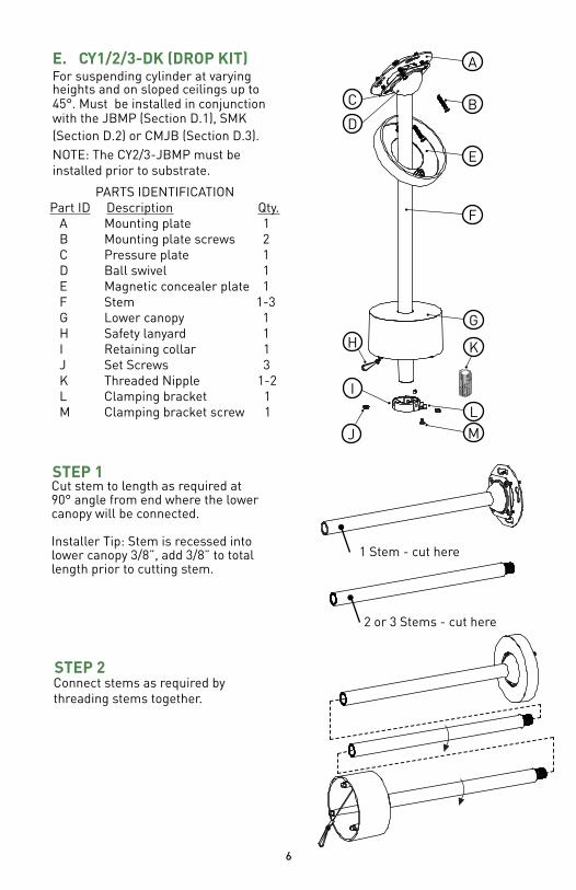
E. CY1/2/3-DK (DROP KIT)For suspending cylinder at varying heights and on sloped ceilings up to 45°. Must be installed in conjunction with the JBMP (Section D.1), SMK (Section D.2) or CMJB (Section D.3).NOTE: The CY2/3-JBMP must be installed prior to substrate.
PARTS IDENTIFICATIONPart ID Description Qty. A Mounting plate 1 B Mounting plate screws 2 C Pressure plate 1 D Ball swivel 1 E Magnetic concealer plate 1 F Stem 1-3 G Lower canopy 1 H Safety lanyard 1 I Retaining collar 1 J Set Screws 3 K Threaded Nipple 1-2 L Clamping bracket 1 M Clamping bracket screw 1
A
C
E
F
G
H
J
I
STEP 1Cut stem to length as required at 90° angle from end where the lower canopy will be connected.
Installer Tip: Stem is recessed into lower canopy 3/8”, add 3/8” to total length prior to cutting stem.
1 Stem - cut here
BD
K
LM
2 or 3 Stems - cut here
STEP 2Connect stems as required by threading stems together.
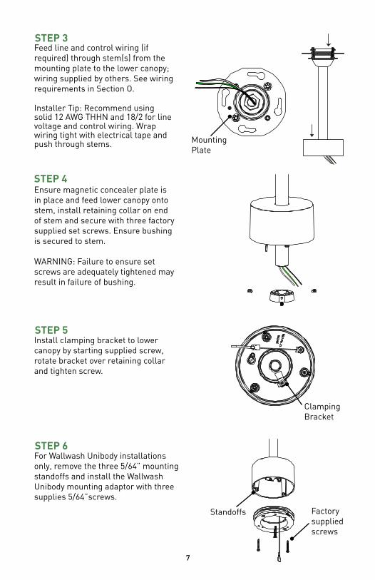
STEP 4Ensure magnetic concealer plate is in place and feed lower canopy onto stem, install retaining collar on end of stem and secure with three factory supplied set screws. Ensure bushing is secured to stem.
WARNING: Failure to ensure set screws are adequately tightened may result in failure of bushing.
7
STEP 5Install clamping bracket to lower canopy by starting supplied screw, rotate bracket over retaining collar and tighten screw.
Clamping Bracket
STEP 3Feed line and control wiring (if required) through stem(s) from the mounting plate to the lower canopy; wiring supplied by others. See wiring requirements in Section O.
Installer Tip: Recommend using solid 12 AWG THHN and 18/2 for line voltage and control wiring. Wrap wiring tight with electrical tape and push through stems. Mounting
Plate
STEP 6For Wallwash Unibody installations only, remove the three 5/64” mounting standoffs and install the Wallwash Unibody mounting adaptor with three supplies 5/64”screws.
Factory supplied screws
Standoffs
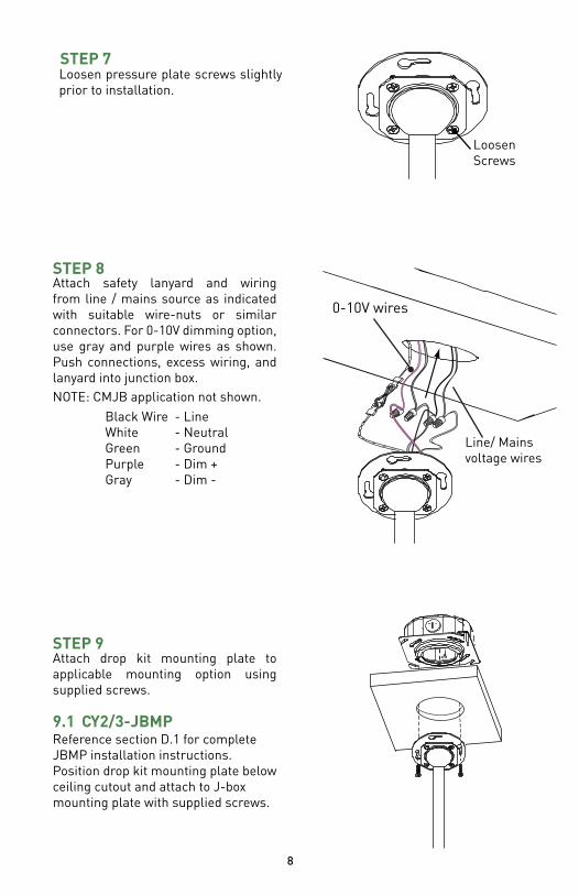
STEP 9Attach drop kit mounting plate to applicable mounting option using supplied screws.
CY2/3-JBMP Reference section D.1 for complete JBMP installation instructions. Position drop kit mounting plate below ceiling cutout and attach to J-box mounting plate with supplied screws.
9.1
Black WireWhiteGreenPurpleGray
- Line- Neutral- Ground- Dim +- Dim -
Attach safety lanyard and wiring from line / mains source as indicated with suitable wire-nuts or similar connectors. For 0-10V dimming option, use gray and purple wires as shown. Push connections, excess wiring, and lanyard into junction box.NOTE: CMJB application not shown.
STEP 8
Line/ Mains voltage wires
0-10V wires
STEP 7Loosen pressure plate screws slightly prior to installation.
Loosen Screws
8
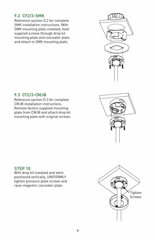
STEP 10With drop kit installed and stem positioned vertically, UNIFORMLY tighten pressure plate screws and raise magnetic concealer plate.
Tighten Screws
9
CY2/3-SMKReference section D.2 for complete SMK installation instructions. With SMK mounting plate installed, feed supplied screws through drop kit mounting plate and concealer plate and attach to SMK mounting plate.
9.2
CY2/3-CMJB Reference section D.3 for complete CMJB installation instructions. Remove factory supplied mounting plate from CMJB and attach drop kit mounting plate with original screws.
9.3
10
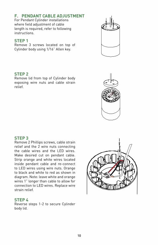
For Pendant Cylinder installations where field adjustment of cable length is required, refer to following instructions.
F. PENDANT CABLE ADJUSTMENT
STEP 1Remove 3 screws located on top of Cylinder body using 1/16” Allen key.
STEP 2Remove lid from top of Cylinder body exposing wire nuts and cable strain relief.
STEP 3Remove 2 Phillips screws, cable strain relief and the 2 wire nuts connecting the cable wires and the LED wires. Make desired cut on pendant cable. Strip orange and white wires located inside pendant cable and re-connect to LED wires using wire nuts. Orange to black and white to red as shown in diagram. Note: leave white and orange wires 1” longer than cable to allow for connection to LED wires. Replace wire strain relief.
STEP 4Reverse steps 1-2 to secure Cylinder body lid.
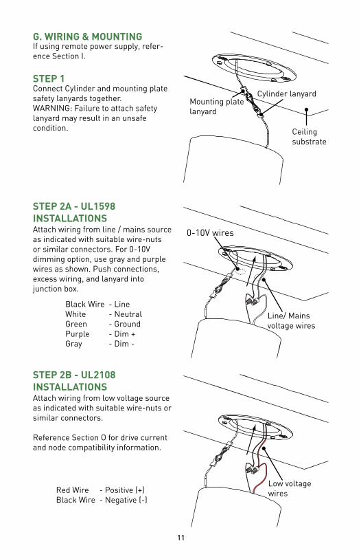
Cylinder lanyardMounting plate lanyard
Line/ Mains voltage wires
0-10V wires
11
Connect Cylinder and mounting plate safety lanyards together.WARNING: Failure to attach safety lanyard may result in an unsafe condition.
G. WIRING & MOUNTING
Black WireWhiteGreenPurpleGray
- Line- Neutral- Ground- Dim +- Dim -
STEP 1
Attach wiring from line / mains source as indicated with suitable wire-nuts or similar connectors. For 0-10V dimming option, use gray and purple wires as shown. Push connections, excess wiring, and lanyard into junction box.
STEP 2A - UL1598 INSTALLATIONS
If using remote power supply, refer-ence Section I.
Ceilingsubstrate
Low voltage wires
Attach wiring from low voltage source as indicated with suitable wire-nuts or similar connectors.
Reference Section O for drive current and node compatibility information.
STEP 2B - UL2108 INSTALLATIONS
Red WireBlack Wire
- Positive (+)- Negative (-)
12
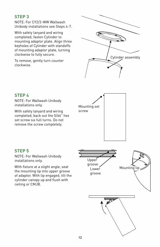
Cylinder assembly
NOTE: For CY2/3-WW Wallwash Unibody installations see Steps 4-7.
With safety lanyard and wiring completed, fasten Cylinder to mounting adaptor plate. Align three keyholes of Cylinder with standoffs of mounting adaptor plate, turning clockwise to fully secure.
To remove, gently turn counter clockwise.
STEP 3
NOTE: For Wallwash Unibody installations only.
With safety lanyard and wiring completed, back out the 5/64” hex set screw six full turns. Do not remove the screw completely.
STEP 4
Mounting set screw
NOTE: For Wallwash Unibody installations only.
With fixture at a slight angle, seat the mounting lip into upper groove of adaptor. With lip engaged, tilt the cylinder canopy up and flush with ceiling or CMJB.
STEP 5
Mounting lip
Upper groove
Lower groove
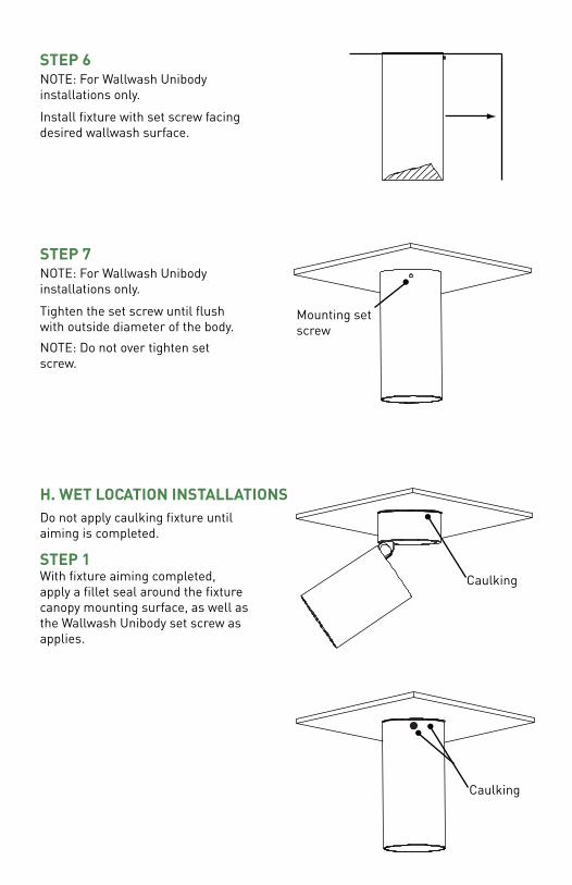
STEP 1With fixture aiming completed, apply a fillet seal around the fixture canopy mounting surface, as well as the Wallwash Unibody set screw as applies.
H. WET LOCATION INSTALLATIONSDo not apply caulking fixture until aiming is completed.
Caulking
NOTE: For Wallwash Unibody installations only.
Install fixture with set screw facing desired wallwash surface.
STEP 6
NOTE: For Wallwash Unibody installations only.
Tighten the set screw until flush with outside diameter of the body.
NOTE: Do not over tighten set screw.
STEP 7
Caulking
Mounting set screw
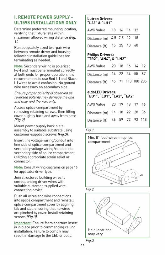
I. REMOTE POWER SUPPLY - UL1598 INSTALLATIONS ONLY
14
Determine preferred mounting location, verifying that fixture falls within maximum allowed wiring distance (Fig. 1).
Run adequately sized two-pair wire between remote driver and housing, following installation guidelines for terminating as needed.
Note: Secondary wiring is polarized (+/-) and must be terminated correctly at both ends for proper operation. It is recommended to use Red (+) and Black (-) wires to avoid confusion. No ground wire necessary on secondary side.
Ensure proper polarity is observed as reversed polarity may damage the unit and may void the warranty.
Access splice compartment by removing retaining screws, then tilting cover slightly back and away from base (Fig.2).
Mount power supply back plate assembly to suitable substrate using customer-supplied screws (Fig.3).
Insert line voltage wiring/conduit into line side of splice compartment and secondary voltage wiring/conduit into secondary side of splice compartment, utilizing appropriate strain relief or connector.
Note: Consult wiring diagrams on page 16 for applicable driver type.
Join structured building wires to corresponding driver wires with suitable customer-supplied wire connecting device.
Push all wires and wire connections into splice compartment and reinstall splice compartment cover by aligning tab and slot, ensuring that no wires are pinched by cover. Install retaining screws (Fig.3).
Important: Ensure foam aperture insert is in place prior to commencing ceiling installation. Failure to comply may result in damage to the LED or optic.
Fig.3
Hole locationsmay vary
Fig.2
Min. 8” feed wires in splice compartment
AWG Value 20 19 18 17 16
Distance (m) 14 18 22 28 36
Distance (ft) 46 59 72 92 118
Fig.1
eldoLED Drivers: “ED1”, “LD1”, “LA2”, “EA2”
Lutron Drivers: “L23” & “LH1”
AWG Value 18 16 14 12
Distance (m) 4.5 7.5 12 18
Distance (ft) 15 25 40 60
Philips Drivers: “TR2”, “AN4”, & “LN2”
AWG Value 20 18 16 14 12
Distance (m) 14 22 34 55 87
Distance (ft) 45 71 113 180 285
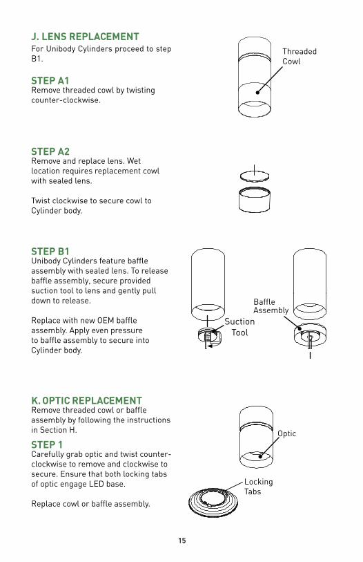
Threaded Cowl
For Unibody Cylinders proceed to step B1.
J. LENS REPLACEMENT
STEP A1Remove threaded cowl by twisting counter-clockwise.
STEP A2Remove and replace lens. Wet location requires replacement cowl with sealed lens.
Twist clockwise to secure cowl to Cylinder body.
STEP B1Unibody Cylinders feature baffle assembly with sealed lens. To release baffle assembly, secure provided suction tool to lens and gently pull down to release.
Replace with new OEM baffle assembly. Apply even pressure to baffle assembly to secure into Cylinder body.
STEP 1Carefully grab optic and twist counter-clockwise to remove and clockwise to secure. Ensure that both locking tabs of optic engage LED base.
Replace cowl or baffle assembly.
Remove threaded cowl or baffle assembly by following the instructions in Section H.
K. OPTIC REPLACEMENT
Optic
Locking Tabs
15
Baffle Assembly
Suction Tool
16
Driver
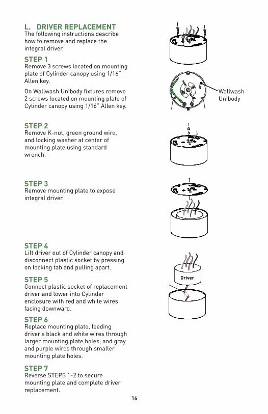
The following instructions describe how to remove and replace the integral driver.
L. DRIVER REPLACEMENT
STEP 1Remove 3 screws located on mounting plate of Cylinder canopy using 1/16” Allen key.
On Wallwash Unibody fixtures remove 2 screws located on mounting plate of Cylinder canopy using 1/16” Allen key.
STEP 2Remove K-nut, green ground wire, and locking washer at center of mounting plate using standard wrench.
STEP 3Remove mounting plate to expose integral driver.
STEP 7Reverse STEPS 1-2 to secure mounting plate and complete driver replacement.
STEP 5Connect plastic socket of replacement driver and lower into Cylinder enclosure with red and white wires facing downward.
STEP 6Replace mounting plate, feeding driver’s black and white wires through larger mounting plate holes, and gray and purple wires through smaller mounting plate holes.
STEP 4Lift driver out of Cylinder canopy and disconnect plastic socket by pressing on locking tab and pulling apart.
Wallwash Unibody
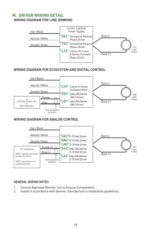
DRIVER WIRING DETAILM.
17
Hot / Black
Neutral / White
Ground / Green
Red (+)
Black (-)
WIRING DIAGRAM FOR ECOSYSTEM AND DIGITAL CONTROL
ToEcoSystem Digital Link
OrDALI Digital Bus
“CE2” Forward & Reverse Phase Driver
“TR2” Forward & Reverse Phase Driver
“L23” Lutron Hi-Lume A Series Forward Phase Driver
Lucifer Lighting Power Supply
Lucifer Lighting Power Supply
Hot / Black
Neutral / White
Ground / Green
Purple
Gray
Wiring Suppliedby Others
LEDLight
Engine
Lucifer Lighting Power Supply
Hot / Black
Neutral / White
Ground / Green
Purple (+)
Gray (-)
Wiring Suppliedby Others
To 0-10V Dimmer
NOTE: Control must switch primary for full off.
NOTE: Connections are polarity sensitive.
WIRING DIAGRAM FOR LINE DIMMING
WIRING DIAGRAM FOR ANALOG CONTROL
GENERAL WIRING NOTES
1. Consult Approved Dimmer List to Ensure Compatibility.2. Install in accordance with dimmer manufacturer’s installation guidelines.
Red (+)
Black (-)
LEDLight
Engine
Red (+)
Black (-)
LEDLight
Engine
“LH1” Lutron H Series EcoSystem Driver
“ED1” eldo SOLOdrive DALI Driver
“LD1” eldo SOLOdrive DALI Driver
“CA2”0-10 Volt Driver
“AN4”0-10 Volt Driver
“LN2”0-10 Volt Driver
“EA2”eldo SOLOdrive 0-10 Volt Driver
“LA2”eldo SOLOdrive 0-10 Volt Driver
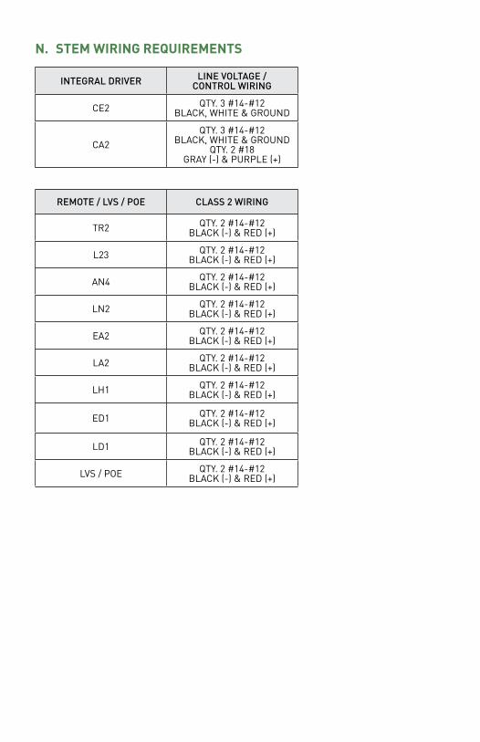
INTEGRAL DRIVER LINE VOLTAGE / CONTROL WIRING
CE2 QTY. 3 #14-#12 BLACK, WHITE & GROUND
CA2QTY. 3 #14-#12
BLACK, WHITE & GROUNDQTY. 2 #18
GRAY (-) & PURPLE (+)
STEM WIRING REQUIREMENTSN.
REMOTE / LVS / POE CLASS 2 WIRING
TR2 QTY. 2 #14-#12 BLACK (-) & RED (+)
L23 QTY. 2 #14-#12 BLACK (-) & RED (+)
AN4 QTY. 2 #14-#12 BLACK (-) & RED (+)
LN2 QTY. 2 #14-#12 BLACK (-) & RED (+)
EA2 QTY. 2 #14-#12 BLACK (-) & RED (+)
LA2 QTY. 2 #14-#12 BLACK (-) & RED (+)
LH1 QTY. 2 #14-#12 BLACK (-) & RED (+)
ED1 QTY. 2 #14-#12 BLACK (-) & RED (+)
LD1 QTY. 2 #14-#12 BLACK (-) & RED (+)
LVS / POE QTY. 2 #14-#12 BLACK (-) & RED (+)
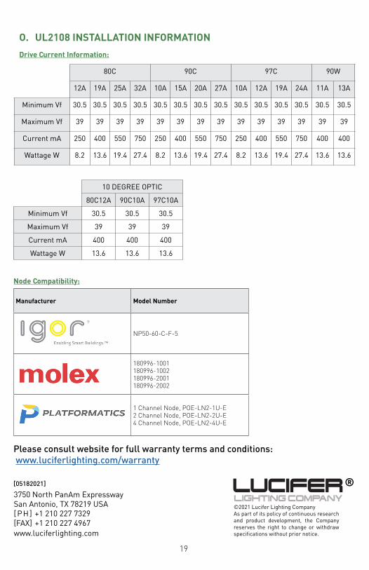
Manufacturer Model Number
NP50-60-C-F-5
180996-1001 180996-1002180996-2001180996-2002
1 Channel Node, POE-LN2-1U-E2 Channel Node, POE-LN2-2U-E4 Channel Node, POE-LN2-4U-E
Node Compatibility:
Drive Current Information:
80C 90C 97C 90W
12A 19A 25A 32A 10A 15A 20A 27A 10A 12A 19A 24A 11A 13A
Minimum Vf 30.5 30.5 30.5 30.5 30.5 30.5 30.5 30.5 30.5 30.5 30.5 30.5 30.5 30.5
Maximum Vf 39 39 39 39 39 39 39 39 39 39 39 39 39 39
Current mA 250 400 550 750 250 400 550 750 250 400 550 750 400 400
Wattage W 8.2 13.6 19.4 27.4 8.2 13.6 19.4 27.4 8.2 13.6 19.4 27.4 13.6 13.6
UL2108 INSTALLATION INFORMATIONO.
10 DEGREE OPTIC
80C12A 90C10A 97C10A
Minimum Vf 30.5 30.5 30.5
Maximum Vf 39 39 39
Current mA 400 400 400
Wattage W 13.6 13.6 13.6
19
3750 North PanAm ExpresswaySan Antonio, TX 78219 USA[PH] +1 210 227 7329[FAX] +1 210 227 4967www.luciferlighting.com
©2021 Lucifer Lighting CompanyAs part of its policy of continuous research and product development, the Company reserves the right to change or withdraw specifications without prior notice.
[05182021] ®
Please consult website for full warranty terms and conditions: www.luciferlighting.com/warranty