Embed Size (px)
Citation preview

CYL SerieS MediuM-dutY
CuStOM weLdedhYdrauLiC CYLinderS
Bore Diameters:1” to 7” (2.54 cm to 17.8 cm)
Stroke Lengths:to 15’ (4.57 m)
For Working Pressures to 3000 PSig (207Bar)
®
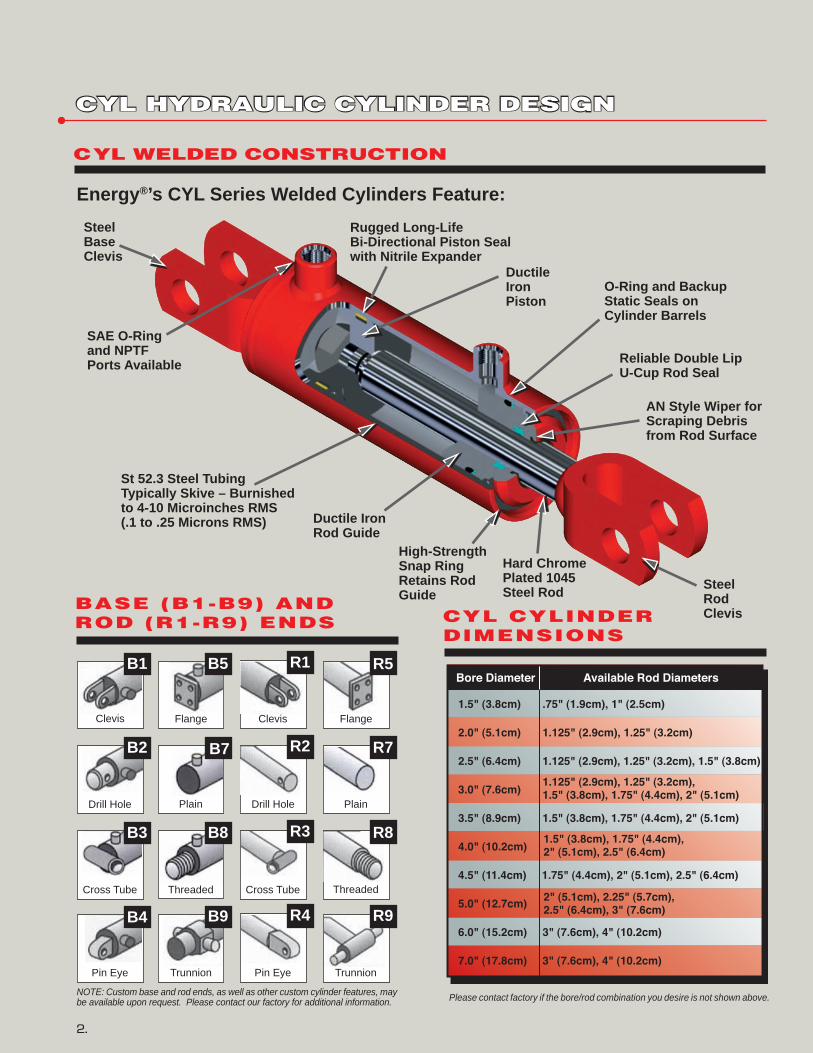
Energy®’s CYL Series Welded Cylinders Feature:
CYL hYdrauLiC CYLinder deSign
2.
CYL weLded COnStruCtiOn
NOTE: Custom base and rod ends, as well as other custom cylinder features, may be available upon request. Please contact our factory for additional information.
BaSe (B1-B9) and rOd (r1-r9) endS CYL CYLinder
diMenSiOnS
AN Style Wiper for Scraping Debris from Rod Surface
Reliable Double Lip U-Cup Rod Seal
SAE O-Ring and NPTF Ports Available
Rugged Long-LifeBi-Directional Piston Seal with Nitrile Expander
Steel Base Clevis
Ductile Iron Rod Guide
O-Ring and Backup Static Seals onCylinder Barrels
Ductile IronPiston
St 52.3 Steel Tubing Typically Skive – Burnished to 4-10 Microinches RMS (.1 to .25 Microns RMS)
Hard Chrome Plated 1045 Steel Rod Steel
Rod Clevis
High-Strength Snap Ring Retains Rod Guide
Clevis Clevis FlangeFlange
Drill Hole Drill HolePlain Plain
Cross Tube Cross TubeThreaded Threaded
Pin Eye Pin EyeTrunnion Trunnion
Please contact factory if the bore/rod combination you desire is not shown above.
B1
B2
B3
B4
B5
B7
B8
B9
R1
R2
R3
R4
R5
R7
R8
R9
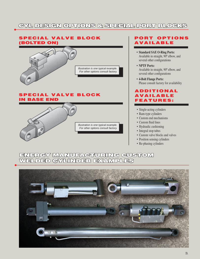
CYL deSign OptiOnS & SpeCiaL pOrt BLOCkS
3.
Illustration is one typical example. For other options consult factory.
SpeCiaL vaLve BLOCk (BOLted On)
SpeCiaL vaLve BLOCk in BaSe end
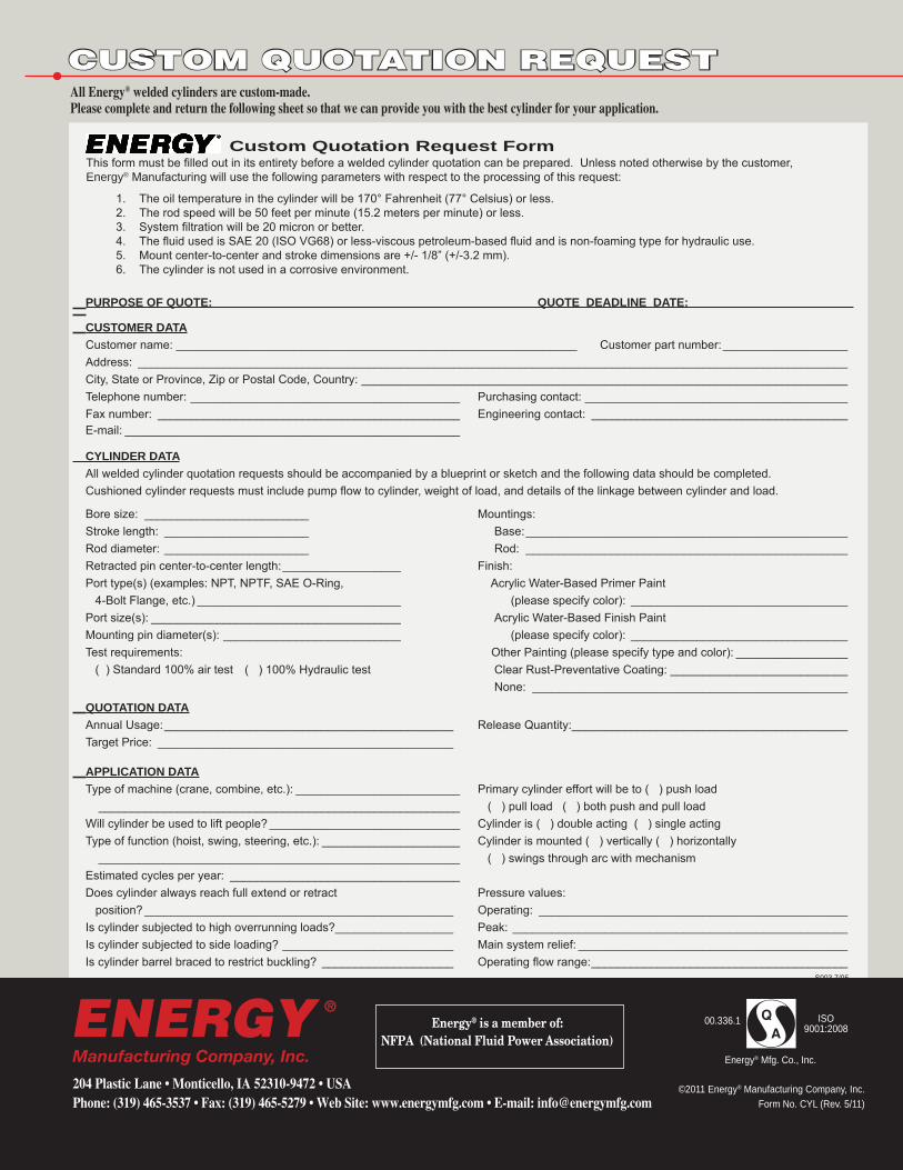
energY ManufaCturing CuStOMweLded CYLinder exaMpLeS
additiOnaLavaiLaBLefeatureS:
• Single-actingcylinders • Ram-typecylinders • Customendmechanisms • Customfluidlines • Hydrauliccushioning • Integralstoptubes • Customvalveblocksandvalves • Positionsensingcylinders • Re-phasingcylinders
pOrt OptiOnS avaiLaBLe
• StandardSAEO-RingPorts: Availableinstraight,90ºelbow,and severalotherconfigurations
• NPTFPorts: Availableinstraight,90ºelbow,and severalotherconfigurations
• 4-BoltFlangePorts: Pleaseconsultfactoryforavailability
Illustration is one typical example. For other options consult factory.
AllEnergy®weldedcylindersarecustom-made.Pleasecompleteandreturnthefollowingsheetsothatwecanprovideyouwiththebestcylinderforyourapplication.
Custom Quotation request FormThis form must be filled out in its entirety before a welded cylinder quotation can be prepared. Unless noted otherwise by the customer,Energy® Manufacturing will use the following parameters with respect to the processing of this request: 1. The oil temperature in the cylinder will be 170° Fahrenheit (77° Celsius) or less. 2. The rod speed will be 50 feet per minute (15.2 meters per minute) or less. 3. System filtration will be 20 micron or better. 4. The fluid used is SAE 20 (ISO VG68) or less-viscous petroleum-based fluid and is non-foaming type for hydraulic use. 5. Mount center-to-center and stroke dimensions are +/- 1/8” (+/-3.2 mm). 6. The cylinder is not used in a corrosive environment.
PURPOSE OF QUOTE: ________________________________________________ QUOTE DEADLINE DATE: ________________________ CUSTOMER DATA Customer name: _____________________________________________________________ Customer part number: ___________________ Address: ____________________________________________________________________________________________________________ City, State or Province, Zip or Postal Code, Country: __________________________________________________________________________ Telephone number: _________________________________________ Purchasing contact: ________________________________________ Fax number: ______________________________________________ Engineering contact: _______________________________________ E-mail: ___________________________________________________ CYLINDER DATA All welded cylinder quotation requests should be accompanied by a blueprint or sketch and the following data should be completed. Cushioned cylinder requests must include pump flow to cylinder, weight of load, and details of the linkage between cylinder and load. Bore size: _________________________ Mountings: Stroke length: ______________________ Base: _________________________________________________ Rod diameter: ______________________ Rod: _________________________________________________ Retracted pin center-to-center length: __________________ Finish: Port type(s) (examples: NPT, NPTF, SAE O-Ring, Acrylic Water-Based Primer Paint 4-Bolt Flange, etc.) _______________________________ (please specify color): _________________________________ Port size(s): ______________________________________ Acrylic Water-Based Finish Paint Mounting pin diameter(s): ___________________________ (please specify color): _________________________________ Test requirements: Other Painting (please specify type and color): _________________ ( ) Standard 100% air test ( ) 100% Hydraulic test Clear Rust-Preventative Coating: ___________________________ None: ________________________________________________
QUOTATION DATA Annual Usage: ____________________________________________ Release Quantity: __________________________________________ Target Price: _____________________________________________
APPLICATION DATA Type of machine (crane, combine, etc.): _________________________ Primary cylinder effort will be to ( ) push load _______________________________________________________ ( ) pull load ( ) both push and pull load Will cylinder be used to lift people? _____________________________ Cylinder is ( ) double acting ( ) single acting Type of function (hoist, swing, steering, etc.): _____________________ Cylinder is mounted ( ) vertically ( ) horizontally _______________________________________________________ ( ) swings through arc with mechanism Estimated cycles per year: ___________________________________ Does cylinder always reach full extend or retract Pressure values: position? _______________________________________________ Operating: _______________________________________________ Is cylinder subjected to high overrunning loads?__________________ Peak: ___________________________________________________ Is cylinder subjected to side loading? __________________________ Main system relief: _________________________________________ Is cylinder barrel braced to restrict buckling? ____________________ Operating flow range: _______________________________________
S003 7/05
CuStOM quOtatiOn requeSt
©2011 Energy® Manufacturing Company, Inc. Form No. CYL (Rev. 5/11)
00.336.1
Energy® Mfg. Co., Inc.
ISO 9001:2008Energy® is a member of:
NFPA (National Fluid Power Association)
204PlasticLane•Monticello,IA52310-9472•USAPhone:(319)465-3537•Fax:(319)465-5279•WebSite:www.energymfg.com•E-mail:[email protected]
ENERGYManufacturing Company, Inc.
®