Embed Size (px)
Citation preview
CYCLOPS TORNADO OSD V1.0 manual Thanks for buying and using CYCLOPS OSD series products, please read this manual
carefully before use.
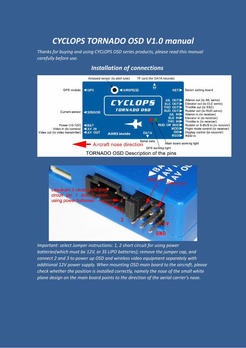
Installation of connections
Important: select Jumper instructions: 1, 2 short circuit for using power
batteries(which must be 12V, or 3S LIPO batteries); remove the jumper cap, and
connect 2 and 3 to power up OSD and wireless video equipment separately with
additional 12V power supply. When mounting OSD main board to the aircraft, please
check whether the position is installed correctly, namely the nose of the small white
plane design on the main board points to the direction of the aerial carrier's nose.
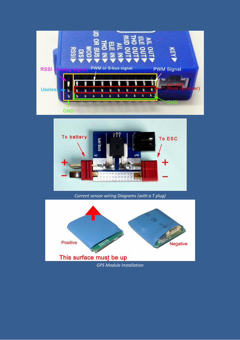
Current sensor wiring Diagrams (with a T plug)
GPS Module Installation
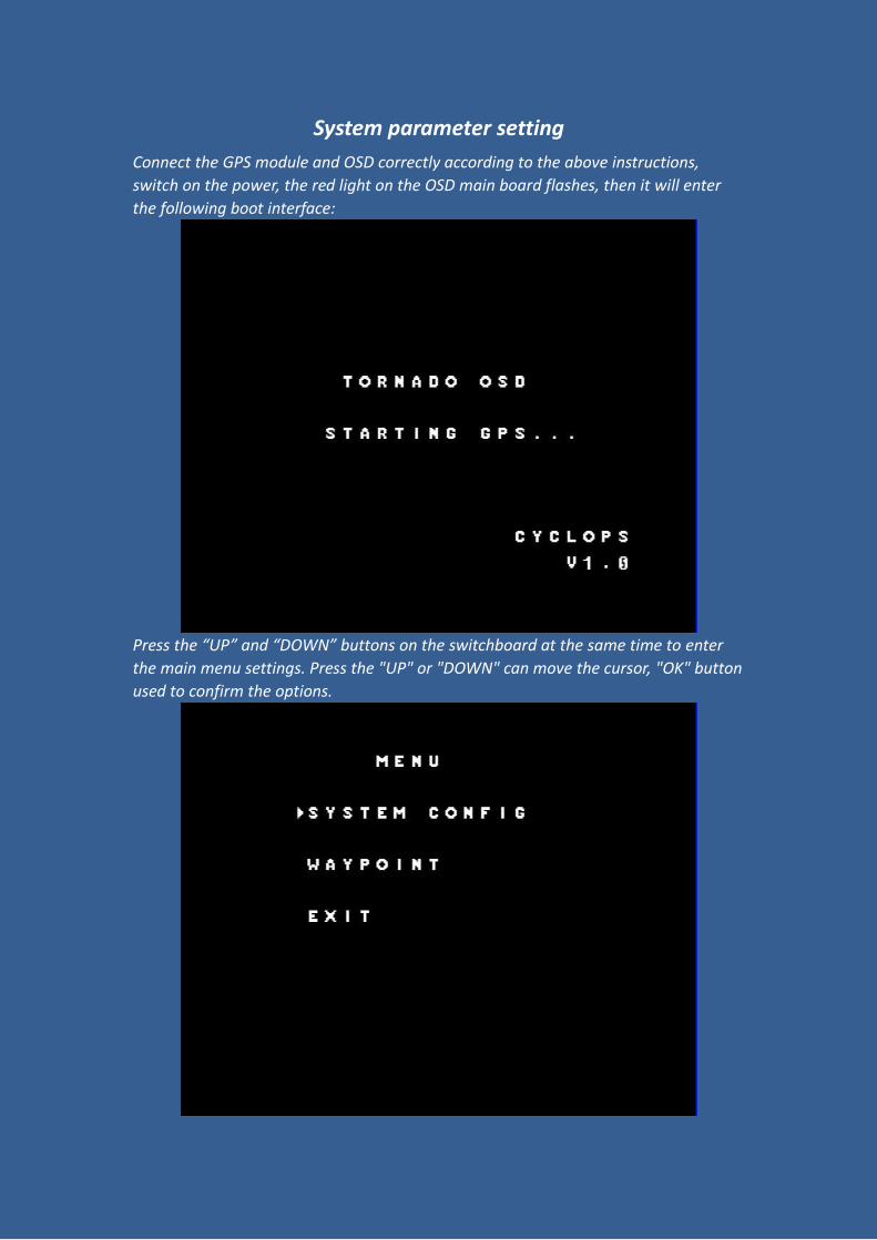
System parameter setting
Connect the GPS module and OSD correctly according to the above instructions,
switch on the power, the red light on the OSD main board flashes, then it will enter
the following boot interface:
Press the “UP” and “DOWN” buttons on the switchboard at the same time to enter
the main menu settings. Press the "UP" or "DOWN" can move the cursor, "OK" button
used to confirm the options.
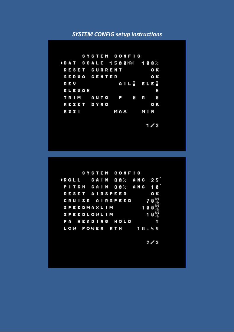
SYSTEM CONFIG setup instructions

Options Setup
instructions Comments
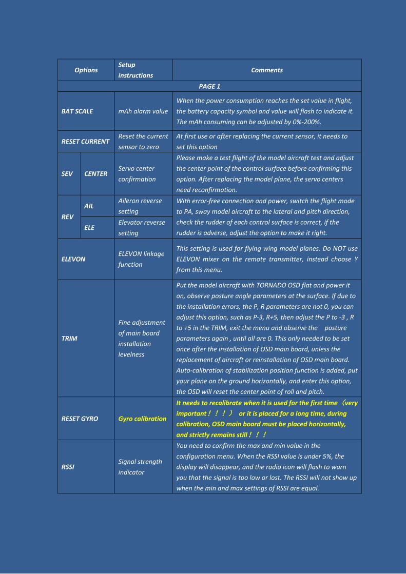
PAGE 1
BAT SCALE mAh alarm value
When the power consumption reaches the set value in flight,
the battery capacity symbol and value will flash to indicate it.
The mAh consuming can be adjusted by 0%-200%.
RESET CURRENT Reset the current
sensor to zero
At first use or after replacing the current sensor, it needs to
set this option
SEV CENTER Servo center
confirmation
Please make a test flight of the model aircraft test and adjust
the center point of the control surface before confirming this
option. After replacing the model plane, the servo centers
need reconfirmation.
REV
AIL Aileron reverse
setting
With error-free connection and power, switch the flight mode
to PA, sway model aircraft to the lateral and pitch direction,
check the rudder of each control surface is correct, if the
rudder is adverse, adjust the option to make it right. ELE
Elevator reverse
setting
ELEVON ELEVON linkage
function
This setting is used for flying wing model planes. Do NOT use
ELEVON mixer on the remote transmitter, instead choose Y
from this menu.
TRIM
Fine adjustment
of main board
installation
levelness
Put the model aircraft with TORNADO OSD flat and power it
on, observe posture angle parameters at the surface. If due to
the installation errors, the P, R parameters are not 0, you can
adjust this option, such as P-3, R+5, then adjust the P to -3 , R
to +5 in the TRIM, exit the menu and observe the posture
parameters again , until all are 0. This only needed to be set
once after the installation of OSD main board, unless the
replacement of aircraft or reinstallation of OSD main board.
Auto-calibration of stabilization position function is added, put
your plane on the ground horizontally, and enter this option,
the OSD will reset the center point of roll and pitch.
RESET GYRO Gyro calibration
It needs to recalibrate when it is used for the first time(very
important!!!) or it is placed for a long time, during
calibration, OSD main board must be placed horizontally,
and strictly remains still!!!
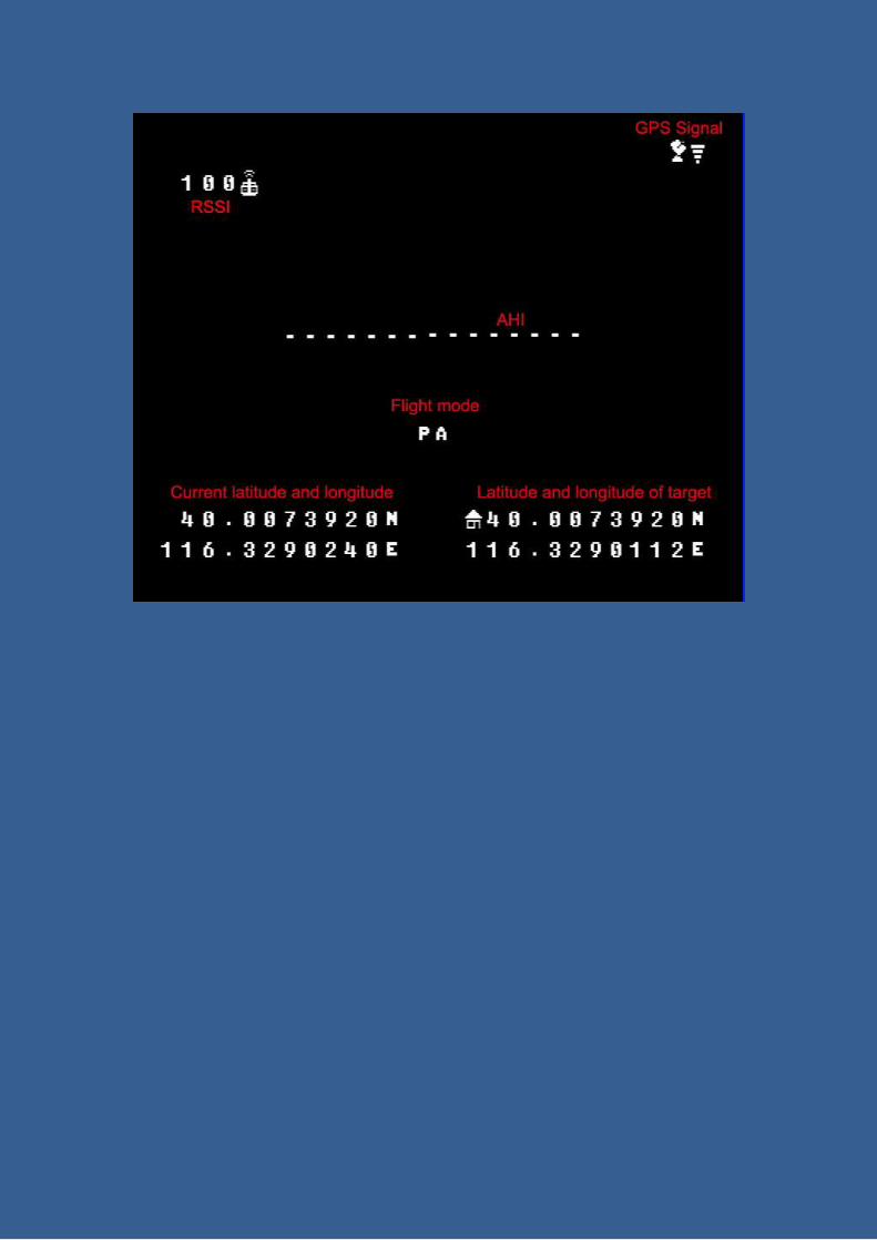
RSSI Signal strength
indicator
You need to confirm the max and min value in the
configuration menu. When the RSSI value is under 5%, the
display will disappear, and the radio icon will flash to warn
you that the signal is too low or lost. The RSSI will not show up
when the min and max settings of RSSI are equal.
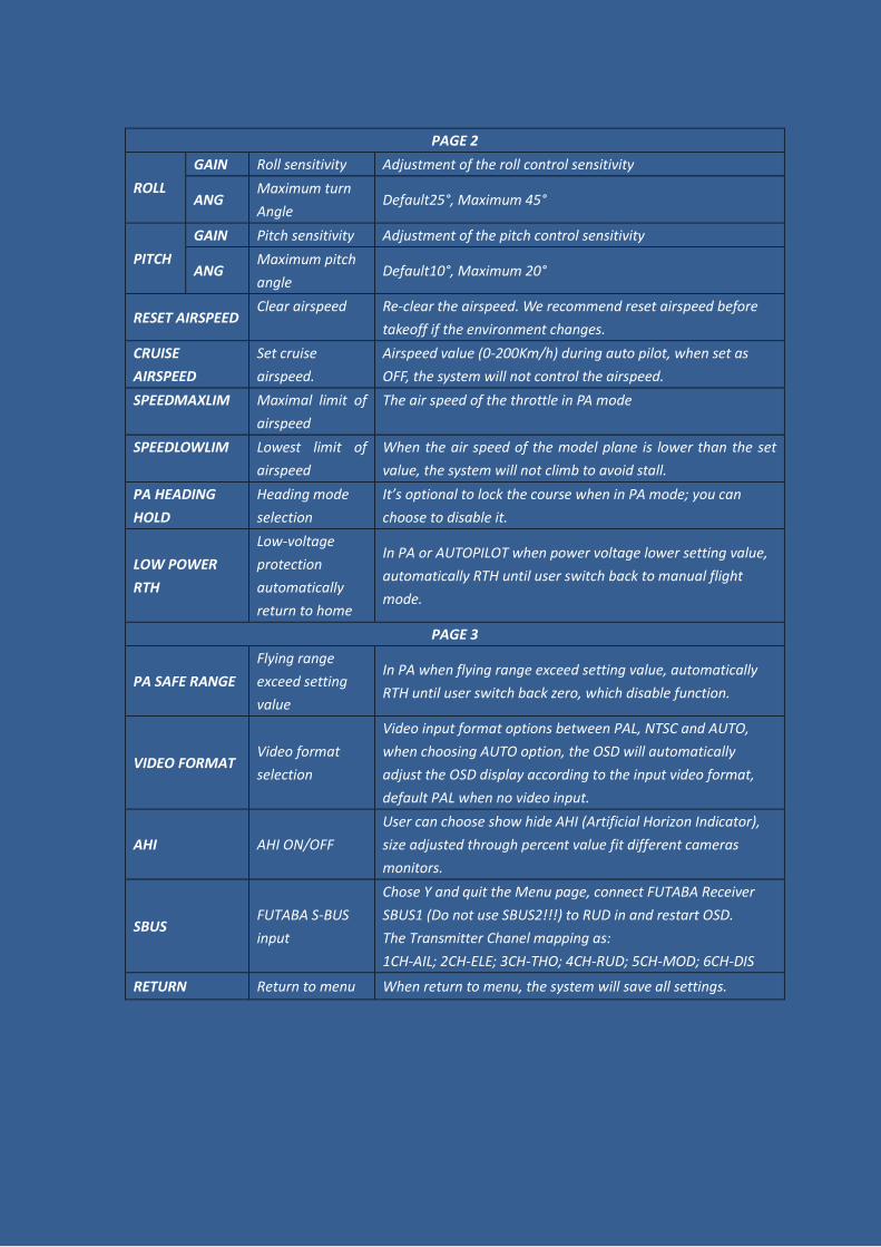
PAGE 2
ROLL
GAIN Roll sensitivity Adjustment of the roll control sensitivity
ANG Maximum turn
Angle Default25°, Maximum 45°
PITCH
GAIN Pitch sensitivity Adjustment of the pitch control sensitivity
ANG Maximum pitch
angle Default10°, Maximum 20°
RESET AIRSPEED Clear airspeed Re-clear the airspeed. We recommend reset airspeed before
takeoff if the environment changes.
CRUISE
AIRSPEED
Set cruise
airspeed.
Airspeed value (0-200Km/h) during auto pilot, when set as
OFF, the system will not control the airspeed.
SPEEDMAXLIM Maximal limit of
airspeed
The air speed of the throttle in PA mode
SPEEDLOWLIM Lowest limit of
airspeed
When the air speed of the model plane is lower than the set
value, the system will not climb to avoid stall.
PA HEADING
HOLD
Heading mode
selection
It’s optional to lock the course when in PA mode; you can
choose to disable it.
LOW POWER
RTH
Low-voltage
protection
automatically
return to home
In PA or AUTOPILOT when power voltage lower setting value,
automatically RTH until user switch back to manual flight
mode.
PAGE 3
PA SAFE RANGE
Flying range
exceed setting
value
In PA when flying range exceed setting value, automatically
RTH until user switch back zero, which disable function.
VIDEO FORMAT Video format
selection
Video input format options between PAL, NTSC and AUTO,
when choosing AUTO option, the OSD will automatically
adjust the OSD display according to the input video format,
default PAL when no video input.
AHI AHI ON/OFF
User can choose show hide AHI (Artificial Horizon Indicator),
size adjusted through percent value fit different cameras
monitors.
SBUS FUTABA S-BUS
input
Chose Y and quit the Menu page, connect FUTABA Receiver
SBUS1 (Do not use SBUS2!!!) to RUD in and restart OSD.
The Transmitter Chanel mapping as:
1CH-AIL; 2CH-ELE; 3CH-THO; 4CH-RUD; 5CH-MOD; 6CH-DIS
RETURN Return to menu When return to menu, the system will save all settings.
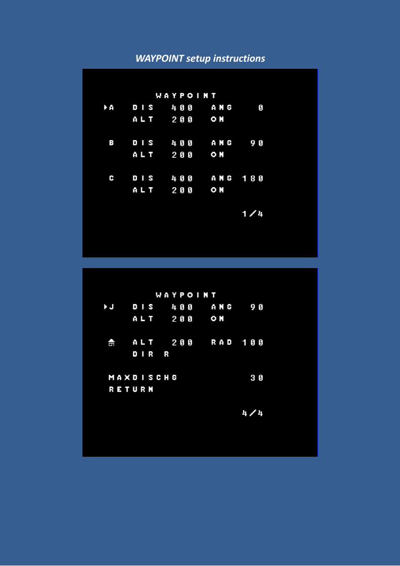
WAYPOINT setup instructions
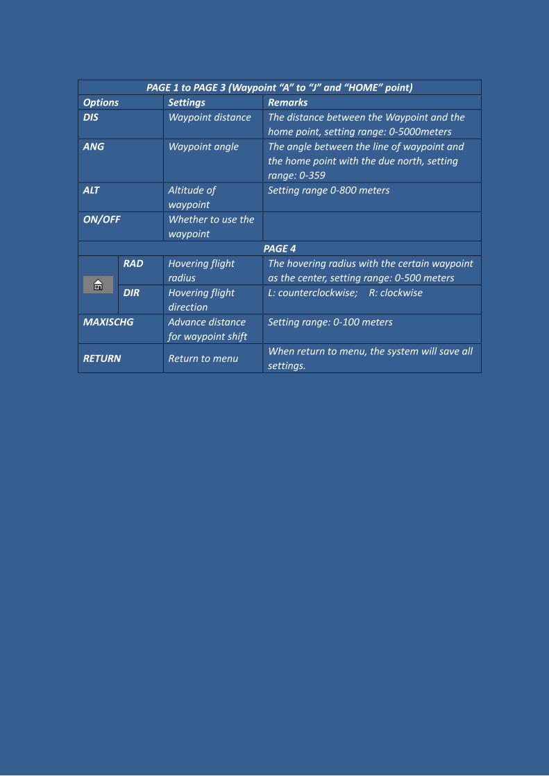
PAGE 1 to PAGE 3 (Waypoint “A” to “J” and “HOME” point)
Options Settings Remarks
DIS Waypoint distance The distance between the Waypoint and the
home point, setting range: 0-5000meters
ANG Waypoint angle The angle between the line of waypoint and
the home point with the due north, setting
range: 0-359
ALT Altitude of
waypoint
Setting range 0-800 meters
ON/OFF Whether to use the
waypoint
PAGE 4
RAD Hovering flight
radius
The hovering radius with the certain waypoint
as the center, setting range: 0-500 meters
DIR Hovering flight
direction
L: counterclockwise; R: clockwise
MAXISCHG Advance distance
for waypoint shift
Setting range: 0-100 meters
RETURN Return to menu When return to menu, the system will save all
settings.
Directions for use
1、 We recommend the clients to use electric power model airplane with good
stability.
2、 Place TORNADO OSD in your plane horizontally, keep the logo plane’s heading
point to your plane’s heading. If the plane slope over 15 degree, the OSD will keep
display the boot interface until you put the plane horizontally.
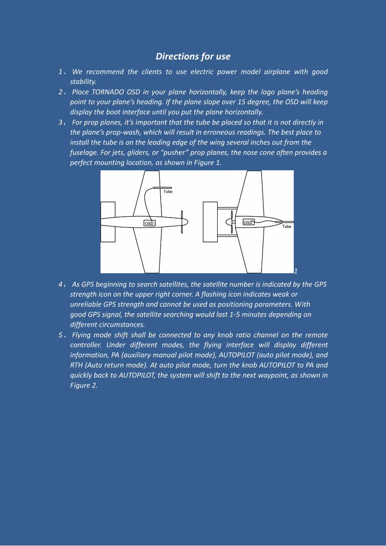
3、 For prop planes, it’s important that the tube be placed so that it is not directly in
the plane’s prop-wash, which will result in erroneous readings. The best place to
install the tube is on the leading edge of the wing several inches out from the
fuselage. For jets, gliders, or “pusher” prop planes, the nose cone often provides a
perfect mounting location, as shown in Figure 1.
1
4、 As GPS beginning to search satellites, the satellite number is indicated by the GPS
strength icon on the upper right corner. A flashing icon indicates weak or
unreliable GPS strength and cannot be used as positioning parameters. With
good GPS signal, the satellite searching would last 1-5 minutes depending on
different circumstances.
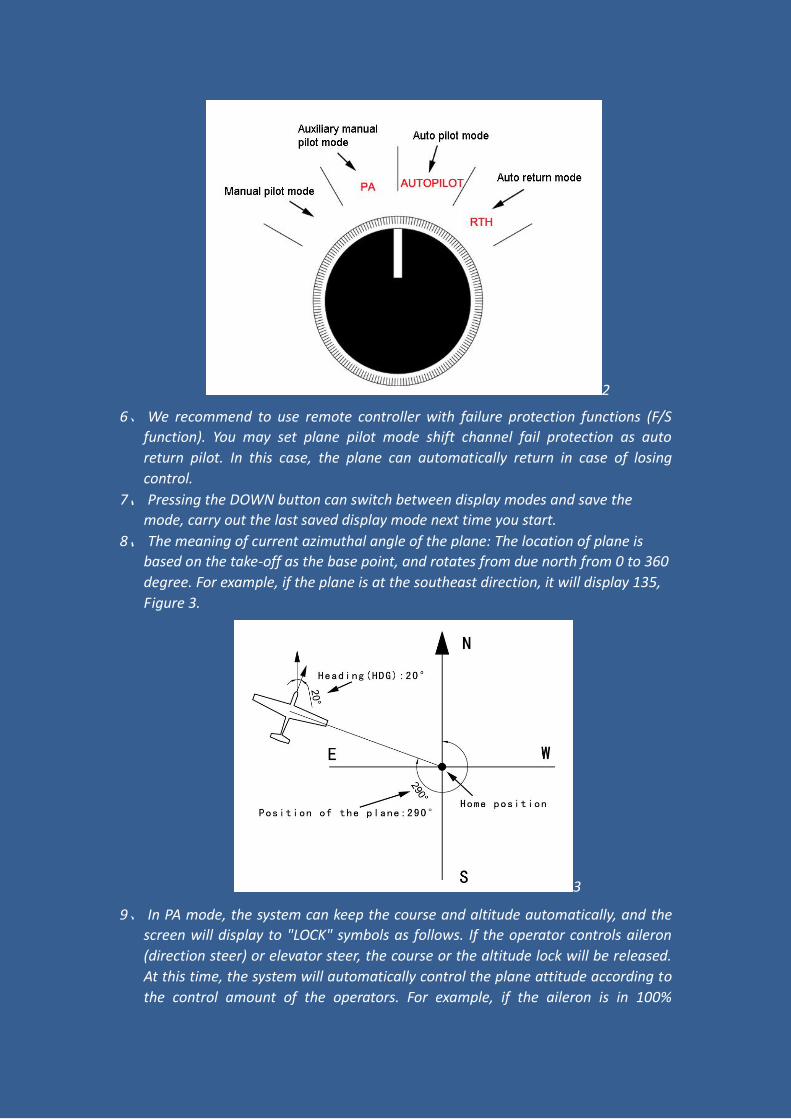
5、 Flying mode shift shall be connected to any knob ratio channel on the remote
controller. Under different modes, the flying interface will display different
information, PA (auxiliary manual pilot mode), AUTOPILOT (auto pilot mode), and
RTH (Auto return mode). At auto pilot mode, turn the knob AUTOPILOT to PA and
quickly back to AUTOPILOT, the system will shift to the next waypoint, as shown in
Figure 2.
2
6、 We recommend to use remote controller with failure protection functions (F/S
function). You may set plane pilot mode shift channel fail protection as auto
return pilot. In this case, the plane can automatically return in case of losing
control.
7、 Pressing the DOWN button can switch between display modes and save the
mode, carry out the last saved display mode next time you start.
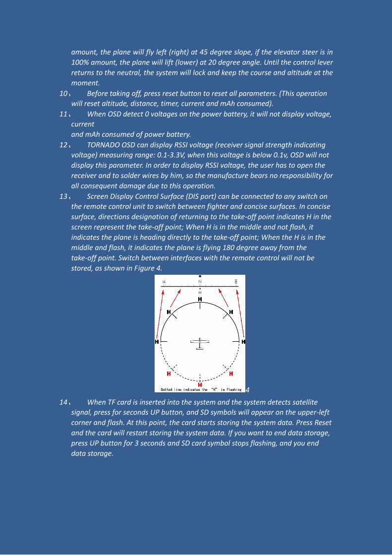
8、 The meaning of current azimuthal angle of the plane: The location of plane is
based on the take-off as the base point, and rotates from due north from 0 to 360
degree. For example, if the plane is at the southeast direction, it will display 135,
Figure 3.
3
9、 In PA mode, the system can keep the course and altitude automatically, and the
screen will display to "LOCK" symbols as follows. If the operator controls aileron
(direction steer) or elevator steer, the course or the altitude lock will be released.
At this time, the system will automatically control the plane attitude according to
the control amount of the operators. For example, if the aileron is in 100%
amount, the plane will fly left (right) at 45 degree slope, if the elevator steer is in
100% amount, the plane will lift (lower) at 20 degree angle. Until the control lever
returns to the neutral, the system will lock and keep the course and altitude at the
moment.
10、 Before taking off, press reset button to reset all parameters. (This operation
will reset altitude, distance, timer, current and mAh consumed).
11、 When OSD detect 0 voltages on the power battery, it will not display voltage,
current
and mAh consumed of power battery.
12、 TORNADO OSD can display RSSI voltage (receiver signal strength indicating
voltage) measuring range: 0.1-3.3V, when this voltage is below 0.1v, OSD will not
display this parameter. In order to display RSSI voltage, the user has to open the
receiver and to solder wires by him, so the manufacture bears no responsibility for
all consequent damage due to this operation.
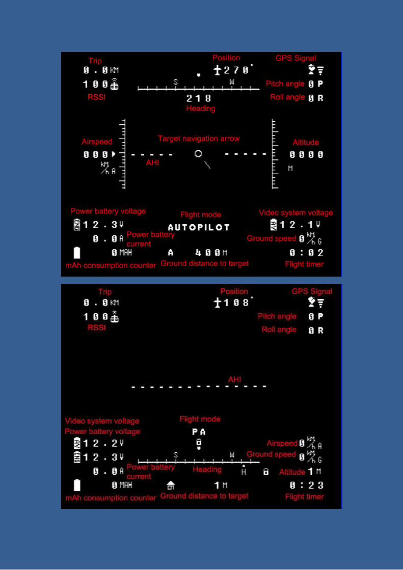
13、 Screen Display Control Surface (DIS port) can be connected to any switch on
the remote control unit to switch between fighter and concise surfaces. In concise
surface, directions designation of returning to the take-off point indicates H in the
screen represent the take-off point; When H is in the middle and not flash, it
indicates the plane is heading directly to the take-off point; When the H is in the
middle and flash, it indicates the plane is flying 180 degree away from the
take-off point. Switch between interfaces with the remote control will not be
stored, as shown in Figure 4.
4
14、 When TF card is inserted into the system and the system detects satellite
signal, press for seconds UP button, and SD symbols will appear on the upper-left
corner and flash. At this point, the card starts storing the system data. Press Reset
and the card will restart storing the system data. If you want to end data storage,
press UP button for 3 seconds and SD card symbol stops flashing, and you end
data storage.
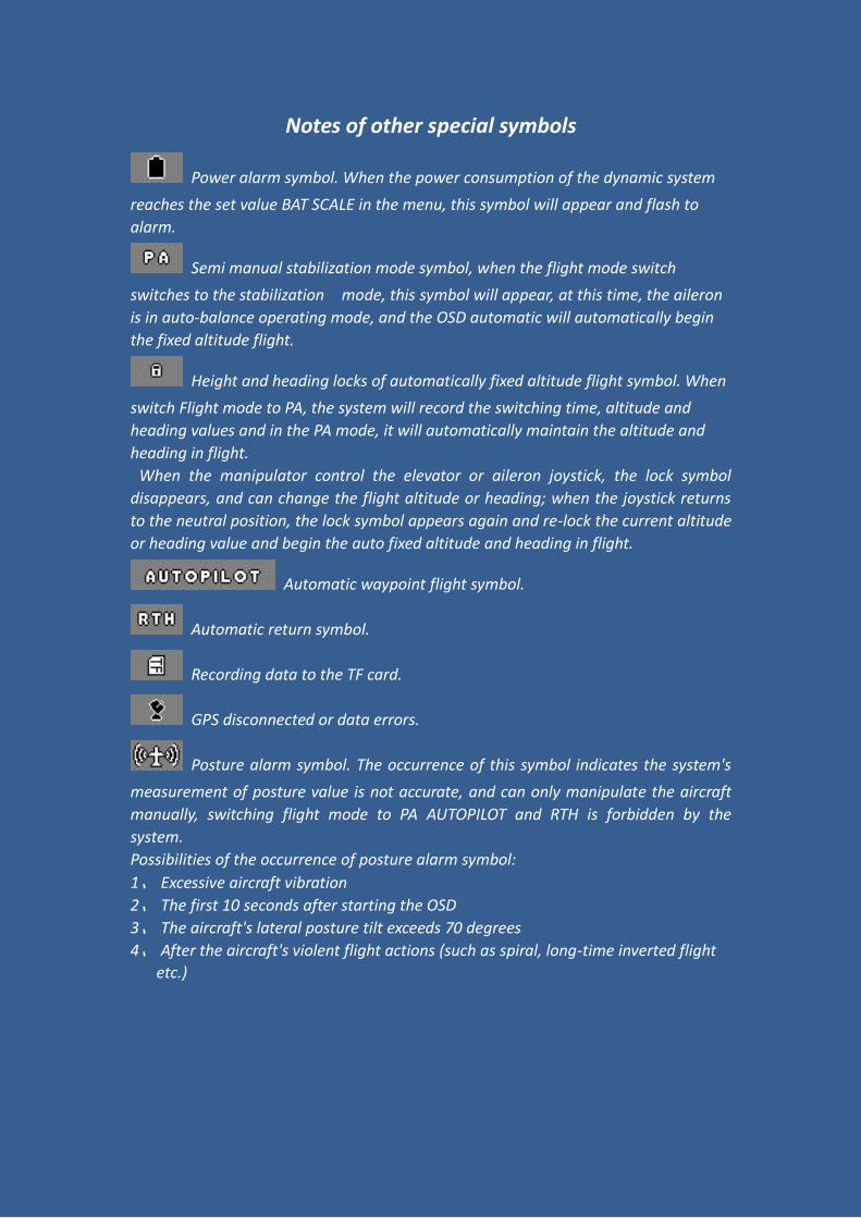
Notes of other special symbols
Power alarm symbol. When the power consumption of the dynamic system
reaches the set value BAT SCALE in the menu, this symbol will appear and flash to
alarm.
Semi manual stabilization mode symbol, when the flight mode switch
switches to the stabilization mode, this symbol will appear, at this time, the aileron
is in auto-balance operating mode, and the OSD automatic will automatically begin
the fixed altitude flight.
Height and heading locks of automatically fixed altitude flight symbol. When
switch Flight mode to PA, the system will record the switching time, altitude and
heading values and in the PA mode, it will automatically maintain the altitude and
heading in flight.
When the manipulator control the elevator or aileron joystick, the lock symbol
disappears, and can change the flight altitude or heading; when the joystick returns
to the neutral position, the lock symbol appears again and re-lock the current altitude
or heading value and begin the auto fixed altitude and heading in flight.
Automatic waypoint flight symbol.
Automatic return symbol.
Recording data to the TF card.
GPS disconnected or data errors.
Posture alarm symbol. The occurrence of this symbol indicates the system's
measurement of posture value is not accurate, and can only manipulate the aircraft
manually, switching flight mode to PA AUTOPILOT and RTH is forbidden by the
system.
Possibilities of the occurrence of posture alarm symbol:
1、 Excessive aircraft vibration
2、 The first 10 seconds after starting the OSD
3、 The aircraft's lateral posture tilt exceeds 70 degrees
4、 After the aircraft's violent flight actions (such as spiral, long-time inverted flight
etc.)
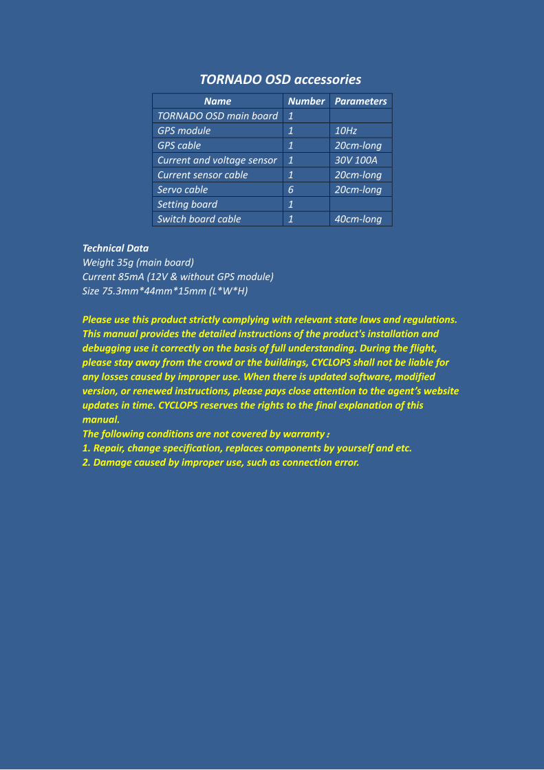
TORNADO OSD accessories
Name Number Parameters
TORNADO OSD main board 1
GPS module 1 10Hz
GPS cable 1 20cm-long
Current and voltage sensor 1 30V 100A
Current sensor cable 1 20cm-long
Servo cable 6 20cm-long
Setting board 1
Switch board cable 1 40cm-long
Technical Data
Weight 35g (main board)
Current 85mA (12V & without GPS module)
Size 75.3mm*44mm*15mm (L*W*H)
Please use this product strictly complying with relevant state laws and regulations.
This manual provides the detailed instructions of the product's installation and
debugging use it correctly on the basis of full understanding. During the flight,
please stay away from the crowd or the buildings, CYCLOPS shall not be liable for
any losses caused by improper use. When there is updated software, modified
version, or renewed instructions, please pays close attention to the agent’s website
updates in time. CYCLOPS reserves the rights to the final explanation of this
manual.
The following conditions are not covered by warranty:
1. Repair, change specification, replaces components by yourself and etc.
2. Damage caused by improper use, such as connection error.
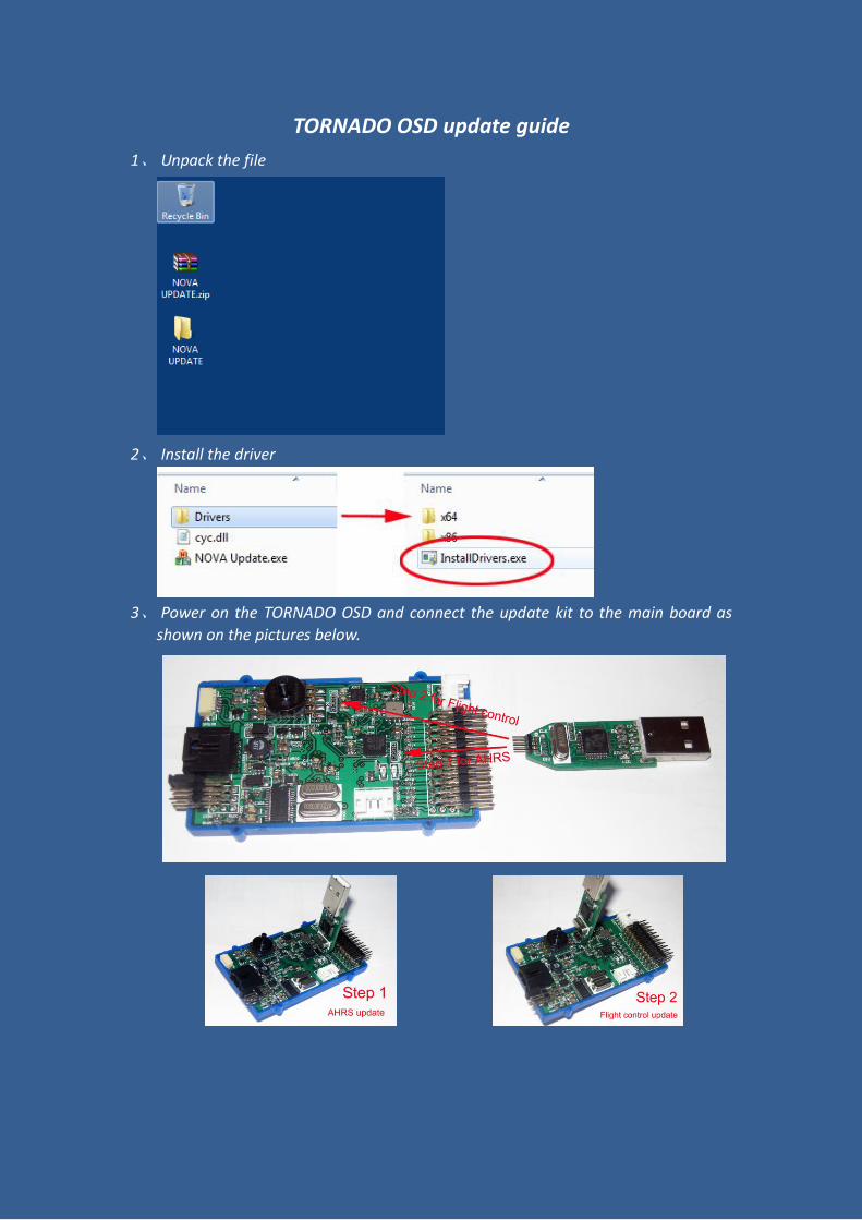
TORNADO OSD update guide
1、 Unpack the file
2、 Install the driver
3、 Power on the TORNADO OSD and connect the update kit to the main board as
shown on the pictures below.
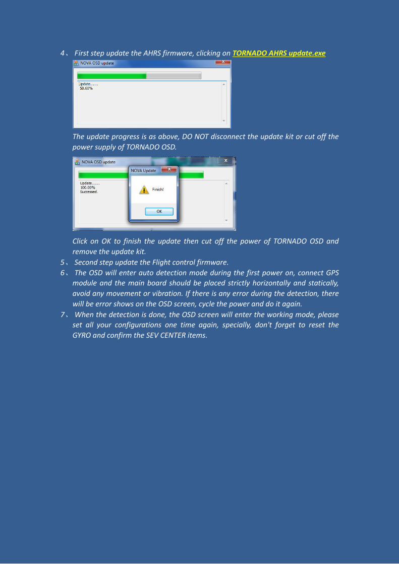
4、 First step update the AHRS firmware, clicking on TORNADO AHRS update.exe
The update progress is as above, DO NOT disconnect the update kit or cut off the
power supply of TORNADO OSD.
Click on OK to finish the update then cut off the power of TORNADO OSD and
remove the update kit.
5、 Second step update the Flight control firmware.
6、 The OSD will enter auto detection mode during the first power on, connect GPS
module and the main board should be placed strictly horizontally and statically,
avoid any movement or vibration. If there is any error during the detection, there
will be error shows on the OSD screen, cycle the power and do it again.
7、 When the detection is done, the OSD screen will enter the working mode, please
set all your configurations one time again, specially, don't forget to reset the
GYRO and confirm the SEV CENTER items.