Embed Size (px)
Citation preview
Composite Structures 94 (2012) 2246–2253
Contents lists available at SciVerse ScienceDirect
Composite Structures
journal homepage: www.elsevier .com/locate /compstruct
Cyclic responses of reinforced concrete composite columns strengthenedin the plastic hinge region by HPFRC mortar
Chang-Geun Cho a, Yun-Yong Kim b,⇑, Luciano Feo c, David Hui d
a School of Architecture, Chosun University, Seosuk-Dong 375, Dong-Gu, Gwangju 501-759, South Koreab Dept. of Civil Engineering, Chungnam National University, South Koreac Dept. of Civil Engineering, University of Salerno, Italyd Dept. of Mechanical Engineering, University of New Orleans, USA
a r t i c l e i n f o
Article history:Available online 2 February 2012
Keywords:High Performance Fiber ReinforcedCementitious composites (HPFRCs)Reinforced concrete composite columnsMultiple-microcracksSeismic strengthening
0263-8223/$ - see front matter Crown Copyright � 2doi:10.1016/j.compstruct.2012.01.025
⇑ Corresponding author. Tel.: +82 42 821 7004; faxE-mail address: [email protected] (Y.-Y. Kim).
a b s t r a c t
The brittleness of concrete raises several concerns due to the lack of strength and ductility in the plastichinge region of reinforced concrete columns. In this study, in order to improve the seismic strength andperformance of reinforced concrete columns, a new method of seismic strengthened reinforced concretecomposite columns was attempted by applying High Performance Fiber Reinforced Cementitious com-posites (HPFRCs) instead of concrete locally in the plastic hinge region of the column. HPFRC has high-ductile tensile strains about 2–5% with sustaining the tensile stress after cracking and develops multiplemicro-cracking behaviors. A series of column tests under cyclic lateral load combined with a constantaxial load was carried out. Three specimens of reinforced concrete composite cantilever columns byapplying the HPFRC instead of concrete locally in the column plastic hinge zone and one of a conventionalreinforced concrete column were designed and manufactured. From the experiments, it was known thatthe developed HPFRC applied reinforced concrete columns not only improved cyclic lateral load anddeformation capacities but also minimized bending and shear cracks in the flexural critical region ofthe reinforced concrete columns.
Crown Copyright � 2012 Published by Elsevier Ltd. All rights reserved.
1. Introduction
Due to the increase in number of severe earthquakes in the late20th century, disaster from the damage/failure of buildings orinfrastructures with huge losses of both human life and propertyis unavoidable. Building or infrastructures built in the past wereeither designed with a relatively lower level of seismic design loador with no consideration of the seismic design concept, especiallyin low-rise building/housing structures. Following the increase ofdamage caused by severe earthquakes all over the world, there isan increased interest in the need for an effective seismic strength-ening and rehabilitation of reinforced concrete columns.
The performance of building structures required to resist severeearthquakes mainly depends on the ability of the columns in thelower-stories to sustain relatively large inelastic deformationswithout a significant loss of load-carrying capacity. However, asshown in Fig. 1, the brittleness and cracking of concrete in the plas-tic hinge region of reinforced concrete columns raises serious con-cerns due to the lack of lateral load-carrying and deformationcapacities of the column, with the column leading to failure caused
012 Published by Elsevier Ltd. All
: +82 42 821 0318.
by flexural cracks of the concrete, yielding and buckling of the lon-gitudinal bars as well as crushing of the concrete in the plastichinge zone [1–3].
Steel jacketing in the plastic hinge region of the reinforced con-crete column was one of the most well-known strengtheningmethods, particularly improving the flexural deformation and load-carrying capacities of the columns [4,5]. Fiber wrapping was alsoperhaps one of the most successful applications of fiber-reinforcedpolymer (FRP), due to the strength enhancement being accompaniedby considerable cost savings over traditional retrofitting alternatives.Fiber reinforced polymer (FRP) could improve the strength and duc-tility of concrete by confining the concrete [6–9]. A number of studiesdealing with improving the strength and ductility of confined con-crete wrapped by FRP jackets have been carried out [10–15].
On the other hand, a number of studies have reported that theuse of high ductile and high performance cementitious fiber-reinforced composites mortar such as High Performance FiberReinforced Cementitious composites (HPFRCs) or EngineeredCementitious Composites (ECCs) can significantly increase the brit-tleness of concrete in tension. In comparison to normal concrete,the material characteristics of HPFRC, as shown in Fig. 2, retain ahigh ductile deformation capacity, with a tensile strain of about2% being caused by multiple fine cracks [16–18]. The developmentof ECC or HPFRC was primarily motivated by the need to improve a
rights reserved.
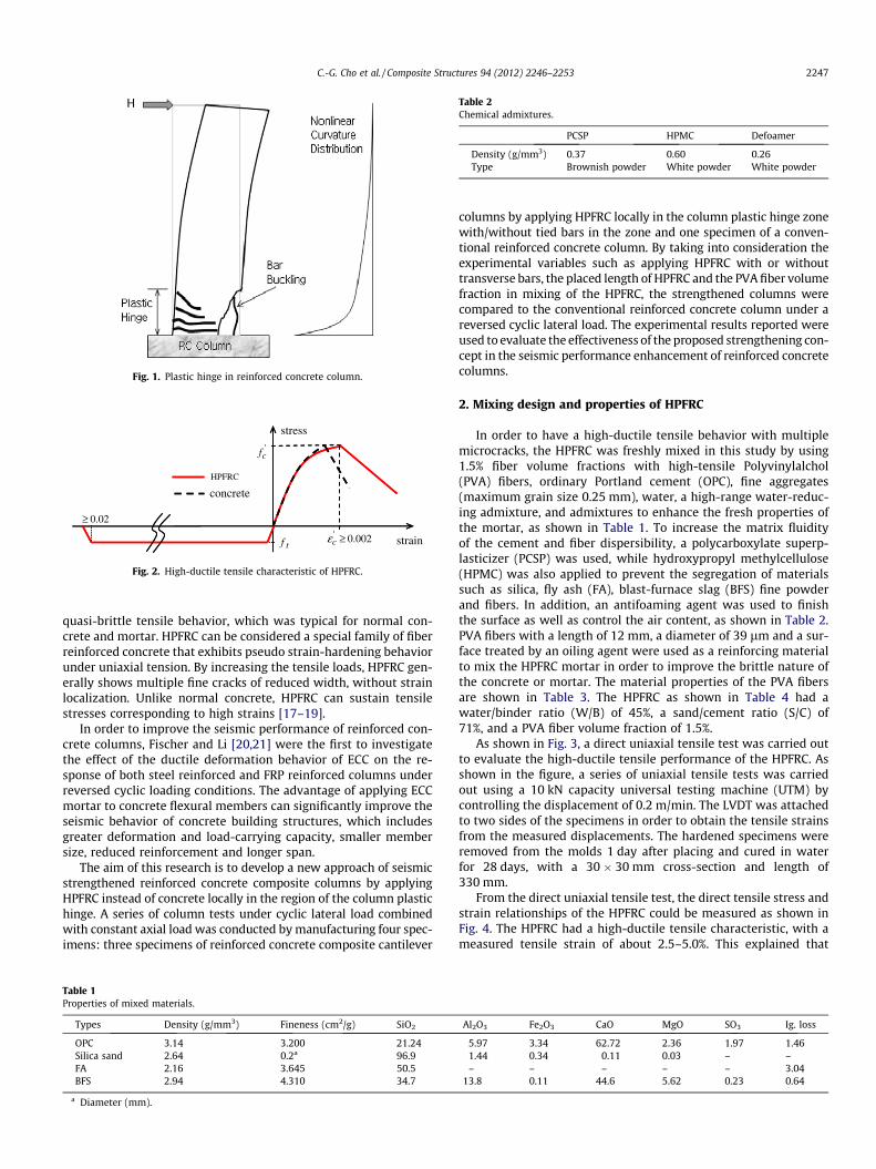
Fig. 1. Plastic hinge in reinforced concrete column.
' 0.002cε ≥
'cf
0.02≥
tf
stress
strain
HPFRC
concrete
Fig. 2. High-ductile tensile characteristic of HPFRC.
Table 2Chemical admixtures.
PCSP HPMC Defoamer
Density (g/mm3) 0.37 0.60 0.26Type Brownish powder White powder White powder
C.-G. Cho et al. / Composite Structures 94 (2012) 2246–2253 2247
quasi-brittle tensile behavior, which was typical for normal con-crete and mortar. HPFRC can be considered a special family of fiberreinforced concrete that exhibits pseudo strain-hardening behaviorunder uniaxial tension. By increasing the tensile loads, HPFRC gen-erally shows multiple fine cracks of reduced width, without strainlocalization. Unlike normal concrete, HPFRC can sustain tensilestresses corresponding to high strains [17–19].
In order to improve the seismic performance of reinforced con-crete columns, Fischer and Li [20,21] were the first to investigatethe effect of the ductile deformation behavior of ECC on the re-sponse of both steel reinforced and FRP reinforced columns underreversed cyclic loading conditions. The advantage of applying ECCmortar to concrete flexural members can significantly improve theseismic behavior of concrete building structures, which includesgreater deformation and load-carrying capacity, smaller membersize, reduced reinforcement and longer span.
The aim of this research is to develop a new approach of seismicstrengthened reinforced concrete composite columns by applyingHPFRC instead of concrete locally in the region of the column plastichinge. A series of column tests under cyclic lateral load combinedwith constant axial load was conducted by manufacturing four spec-imens: three specimens of reinforced concrete composite cantilever
Table 1Properties of mixed materials.
Types Density (g/mm3) Fineness (cm2/g) SiO2
OPC 3.14 3.200 21.24Silica sand 2.64 0.2a 96.9FA 2.16 3.645 50.5BFS 2.94 4.310 34.7
a Diameter (mm).
columns by applying HPFRC locally in the column plastic hinge zonewith/without tied bars in the zone and one specimen of a conven-tional reinforced concrete column. By taking into consideration theexperimental variables such as applying HPFRC with or withouttransverse bars, the placed length of HPFRC and the PVA fiber volumefraction in mixing of the HPFRC, the strengthened columns werecompared to the conventional reinforced concrete column under areversed cyclic lateral load. The experimental results reported wereused to evaluate the effectiveness of the proposed strengthening con-cept in the seismic performance enhancement of reinforced concretecolumns.
2. Mixing design and properties of HPFRC
In order to have a high-ductile tensile behavior with multiplemicrocracks, the HPFRC was freshly mixed in this study by using1.5% fiber volume fractions with high-tensile Polyvinylalchol(PVA) fibers, ordinary Portland cement (OPC), fine aggregates(maximum grain size 0.25 mm), water, a high-range water-reduc-ing admixture, and admixtures to enhance the fresh properties ofthe mortar, as shown in Table 1. To increase the matrix fluidityof the cement and fiber dispersibility, a polycarboxylate superp-lasticizer (PCSP) was used, while hydroxypropyl methylcellulose(HPMC) was also applied to prevent the segregation of materialssuch as silica, fly ash (FA), blast-furnace slag (BFS) fine powderand fibers. In addition, an antifoaming agent was used to finishthe surface as well as control the air content, as shown in Table 2.PVA fibers with a length of 12 mm, a diameter of 39 lm and a sur-face treated by an oiling agent were used as a reinforcing materialto mix the HPFRC mortar in order to improve the brittle nature ofthe concrete or mortar. The material properties of the PVA fibersare shown in Table 3. The HPFRC as shown in Table 4 had awater/binder ratio (W/B) of 45%, a sand/cement ratio (S/C) of71%, and a PVA fiber volume fraction of 1.5%.
As shown in Fig. 3, a direct uniaxial tensile test was carried outto evaluate the high-ductile tensile performance of the HPFRC. Asshown in the figure, a series of uniaxial tensile tests was carriedout using a 10 kN capacity universal testing machine (UTM) bycontrolling the displacement of 0.2 m/min. The LVDT was attachedto two sides of the specimens in order to obtain the tensile strainsfrom the measured displacements. The hardened specimens wereremoved from the molds 1 day after placing and cured in waterfor 28 days, with a 30 � 30 mm cross-section and length of330 mm.
From the direct uniaxial tensile test, the direct tensile stress andstrain relationships of the HPFRC could be measured as shown inFig. 4. The HPFRC had a high-ductile tensile characteristic, with ameasured tensile strain of about 2.5–5.0%. This explained that
Al2O3 Fe2O3 CaO MgO SO3 Ig. loss
5.97 3.34 62.72 2.36 1.97 1.461.44 0.34 0.11 0.03 – –– – – – – 3.04
13.8 0.11 44.6 5.62 0.23 0.64
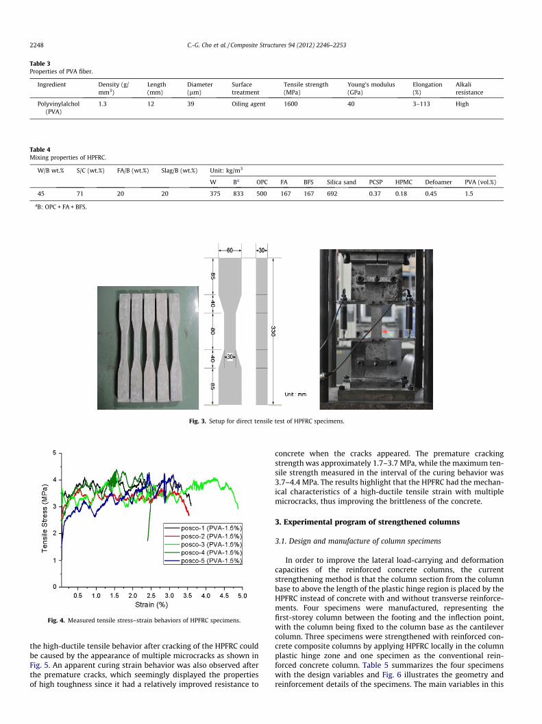
Table 3Properties of PVA fiber.
Ingredient Density (g/mm3)
Length(mm)
Diameter(lm)
Surfacetreatment
Tensile strength(MPa)
Young’s modulus(GPa)
Elongation(%)
Alkaliresistance
Polyvinylalchol(PVA)
1.3 12 39 Oiling agent 1600 40 3–113 High
Table 4Mixing properties of HPFRC.
W/B wt.% S/C (wt.%) FA/B (wt.%) Slag/B (wt.%) Unit: kg/m3
W Ba OPC FA BFS Silica sand PCSP HPMC Defoamer PVA (vol.%)
45 71 20 20 375 833 500 167 167 692 0.37 0.18 0.45 1.5
aB: OPC + FA + BFS.
Fig. 3. Setup for direct tensile test of HPFRC specimens.
Fig. 4. Measured tensile stress–strain behaviors of HPFRC specimens.
2248 C.-G. Cho et al. / Composite Structures 94 (2012) 2246–2253
the high-ductile tensile behavior after cracking of the HPFRC couldbe caused by the appearance of multiple microcracks as shown inFig. 5. An apparent curing strain behavior was also observed afterthe premature cracks, which seemingly displayed the propertiesof high toughness since it had a relatively improved resistance to
concrete when the cracks appeared. The premature crackingstrength was approximately 1.7–3.7 MPa, while the maximum ten-sile strength measured in the interval of the curing behavior was3.7–4.4 MPa. The results highlight that the HPFRC had the mechan-ical characteristics of a high-ductile tensile strain with multiplemicrocracks, thus improving the brittleness of the concrete.
3. Experimental program of strengthened columns
3.1. Design and manufacture of column specimens
In order to improve the lateral load-carrying and deformationcapacities of the reinforced concrete columns, the currentstrengthening method is that the column section from the columnbase to above the length of the plastic hinge region is placed by theHPFRC instead of concrete with and without transverse reinforce-ments. Four specimens were manufactured, representing thefirst-storey column between the footing and the inflection point,with the column being fixed to the column base as the cantilevercolumn. Three specimens were strengthened with reinforced con-crete composite columns by applying HPFRC locally in the columnplastic hinge zone and one specimen as the conventional rein-forced concrete column. Table 5 summarizes the four specimenswith the design variables and Fig. 6 illustrates the geometry andreinforcement details of the specimens. The main variables in this
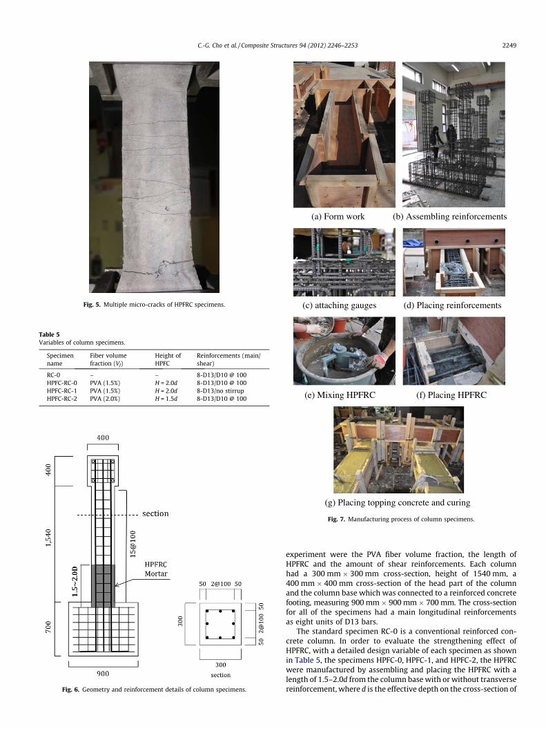
Fig. 5. Multiple micro-cracks of HPFRC specimens.
Table 5Variables of column specimens.
Specimenname
Fiber volumefraction (Vf)
Height ofHPFC
Reinforcements (main/shear)
RC-0 – – 8-D13/D10 @ 100HPFC-RC-0 PVA (1.5%) H = 2.0d 8-D13/D10 @ 100HPFC-RC-1 PVA (1.5%) H = 2.0d 8-D13/no stirrupHPFC-RC-2 PVA (2.0%) H = 1.5d 8-D13/D10 @ 100
Fig. 6. Geometry and reinforcement details of column specimens.
(a) Form work
(c) attaching gauges
(e) Mixing HPFRC
(g) Placing topping concrete and curing
(b) Assembling reinforcements
(d) Placing reinforcements
(f) Placing HPFRC
Fig. 7. Manufacturing process of column specimens.
C.-G. Cho et al. / Composite Structures 94 (2012) 2246–2253 2249
experiment were the PVA fiber volume fraction, the length ofHPFRC and the amount of shear reinforcements. Each columnhad a 300 mm � 300 mm cross-section, height of 1540 mm, a400 mm � 400 mm cross-section of the head part of the columnand the column base which was connected to a reinforced concretefooting, measuring 900 mm� 900 mm� 700 mm. The cross-sectionfor all of the specimens had a main longitudinal reinforcementsas eight units of D13 bars.
The standard specimen RC-0 is a conventional reinforced con-crete column. In order to evaluate the strengthening effect ofHPFRC, with a detailed design variable of each specimen as shownin Table 5, the specimens HPFC-0, HPFC-1, and HPFC-2, the HPFRCwere manufactured by assembling and placing the HPFRC with alength of 1.5–2.0d from the column base with or without transversereinforcement, where d is the effective depth on the cross-section of
(a) Side view (b) Frontal view
Fig. 8. Setup for cyclic load test of columns.
Fig. 9. Cyclic lateral loading history by displacement control.
2250 C.-G. Cho et al. / Composite Structures 94 (2012) 2246–2253
the column. In the column base, in order to avoid failure induced byconstruction joint between the concrete in the footing and theHPFRC, the HPFRC was placed about 50 mm inside the footing. Forspecimen HPFC-1, the shear reinforcements were not placed atthe height of the HPFRC in order to evaluate the control of shearcracks by HPFRC, while for all the other cases, the shear reinforce-ments were assembled with D10 bars with a space of 100 mm.The topping concrete was placed with finishing after placing theHPFRC. The practical manufacturing process of the specimens isshown in Fig. 7.
3.2. Properties of the concrete and reinforcing steel bars
Two types of reinforcing steel bars produced in Korea were usedin the column specimens. The yielding stresses of the reinforcingbars for the main longitudinal bars (D13) and the transverse bars(D10) measured 385 MPa and 383 MPa, respectively. The concretewas mixed with OPC, crushed stones with a maximum aggregatesize of 20 mm, sand and admixtures. The combinations of the con-crete mixtures were designed to satisfy the required strength,workability, and mechanical characteristics of the selected con-crete. Cylindrical specimens were cast to test the compressivestrength of the concrete, with each specimen using £100 �200 mm molds by placing the concrete in three layers and thenexternally vibrated. The specimens were wrapped with plasticimmediately after production and moist-cured for 28 days. Theuniaxial compressive strength of the concrete was measured asthe average of 28.7 MPa.
3.3. Experimental procedure
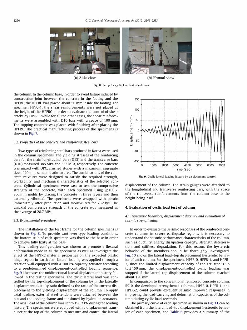
The installation of the test frame for the column specimens isshown in Fig. 8. To provide cantilever-type loading conditions,the bottom stub of each specimen was fixed to the base in orderto achieve fully fixity at the base.
This loading configuration was chosen to promote a flexuraldeformation mode in all the specimens as well as investigate theeffect of the HPFRC material properties on the expected plastichinge region in particular. Lateral loading was applied through areaction wall equipped with a 100 kN-capacity actuator accordingto a predetermined displacement-controlled loading sequence.Fig. 9 illustrates the unidirectional lateral displacement history fol-lowed in the testing specimens. The cyclic lateral load was con-trolled by the top-displacement of the column by l, the laterallydisplacement ductility ratio defined as the ratio of the current dis-placement to the yielding displacement of the column. To applyaxial loading, external steel tendons were attached between thepin and the loading frame and tensioned by hydraulic actuators.The axial load of the column was set to 196.2 kN during the loadinghistory. The specimens were equipped with a displacement trans-ducer at the top of the column to measure and control the lateral
displacement of the column. The strain gauges were attached tothe longitudinal and transverse reinforcing bars, with the spaceof the transverse reinforcements from the column base to theheight being 2.0d.
4. Evaluation of cyclic load test of column
4.1. Hysteretic behaviors, displacement ductility and evaluation ofseismic strengthening
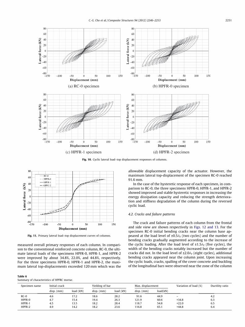
In order to evaluate the seismic responses of the reinforced con-crete columns in severe earthquake regions, it is necessary tounderstand the seismic performance characteristics of the column,such as ductility, energy dissipation capacity, strength deteriora-tion, and stiffness degradation. For this reason, the hystereticbehavior of the members should be thoroughly investigated.Fig. 10 shows the lateral load–top displacement hysteretic behav-ior of each column. For the specimens HPFR-0, HPFR-1, and HPFR-2, since the limited displacement capacity of the actuator is upto ± 150 mm, the displacement-controlled cyclic loading wasstopped if the lateral top displacement of the column reachedabout 120 mm.
In comparison to the conventional reinforced concrete column,RC-0, the developed strengthened columns, HPFR-0, HPFR-1, andHPFR-2, could provide excellent seismic improved responses inimproving the load-carrying and deformation capacities of the col-umn during cyclic load reversals.
The primary curve of each specimen as shown in Fig. 11 can beobtained from the lateral load–top displacement hysteretic behav-ior of each specimen, and Table 6 provides a summary of the
(a) RC-0 specimen (b) HPFR-0 specimen
(c) HPFR-1 specimen (d) HPFR-2 specimen
Fig. 10. Cyclic lateral load–top displacement responses of columns.
Fig. 11. Primary lateral load–top displacement curves of columns.
C.-G. Cho et al. / Composite Structures 94 (2012) 2246–2253 2251
measured overall primary responses of each column. In compari-son to the conventional reinforced concrete column, RC-0, the ulti-mate lateral loads of the specimens HPFR-0, HPFR-1, and HPFR-2were improved by about 34.8%, 22.0%, and 44.8%, respectively.For the three specimens HPFR-0, HPFR-1 and HPFR-2, the maxi-mum lateral top-displacements exceeded 120 mm which was the
Table 6Summary of characteristics of HPFRC mortar.
Specimen name Initial crack Yielding of bar
disp. (mm) load (kN) disp. (mm) load (kN)
RC-0 4.6 17.2 18.6 28.2HPFR-0 4.7 15.4 19.4 26.3HPFR-1 4.5 13.5 18.2 28.4HPFR-2 4.9 14.2 18.2 23.6
allowable displacement capacity of the actuator. However, themaximum lateral top-displacement of the specimen RC-0 reached91.6 mm.
In the case of the hysteretic response of each specimen, in com-parison to RC-0, the three specimens HPFR-0, HPFR-1, and HPFR-2showed improved and stable hysteretic responses in increasing theenergy dissipation capacity and reducing the strength deteriora-tion and stiffness degradation of the column during the reversedcyclic load.
4.2. Cracks and failure patterns
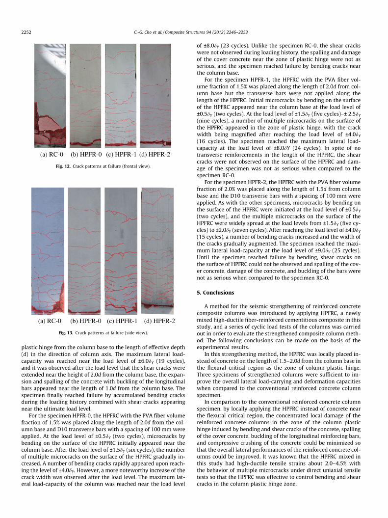
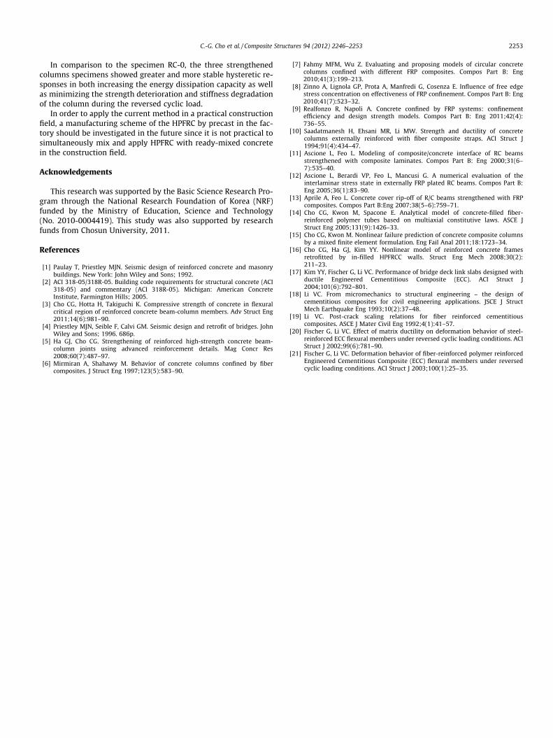
The crack and failure patterns of each column from the frontaland side view are shown respectively in Figs. 12 and 13. For thespecimen RC-0 initial bending cracks near the column base ap-peared at the load level of ±0.5dY (two cycles) and the number ofbending cracks gradually augmented according to the increase ofthe cyclic loading. After the load level of ±1.5dY (five cycles), thewidth of the bending cracks notably increased but the number ofcracks did not. In the load level of ±2.0dY (eight cycles), additionalbending cracks appeared near the column joint. Upon increasingthe cyclic loads, cracks, spalling of the cover concrete and bucklingof the longitudinal bars were observed near the zone of the column
Max. displacement Variation of load (%) Ductility ratio
disp. (mm) load(kN)
91.6 44.9 – 4.2121.9 60.6 +34.8 6.3118.7 54.8 +22.0 6.5116.8 65.1 +44.8 6.4
(a) RC-0 (b) HPFR-0 (c) HPFR-1 (d) HPFR-2
Fig. 12. Crack patterns at failure (frontal view).
(a) RC-0 (b) HPFR-0 (c) HPFR-1 (d) HPFR-2
Fig. 13. Crack patterns at failure (side view).
2252 C.-G. Cho et al. / Composite Structures 94 (2012) 2246–2253
plastic hinge from the column base to the length of effective depth(d) in the direction of column axis. The maximum lateral load-capacity was reached near the load level of ±6.0dY (19 cycles),and it was observed after the load level that the shear cracks wereextended near the height of 2.0d from the column base, the expan-sion and spalling of the concrete with buckling of the longitudinalbars appeared near the length of 1.0d from the column base. Thespecimen finally reached failure by accumulated bending cracksduring the loading history combined with shear cracks appearingnear the ultimate load level.
For the specimen HPFR-0, the HPFRC with the PVA fiber volumefraction of 1.5% was placed along the length of 2.0d from the col-umn base and D10 transverse bars with a spacing of 100 mm wereapplied. At the load level of ±0.5dY (two cycles), microcracks bybending on the surface of the HPFRC initially appeared near thecolumn base. After the load level of ±1.5dY (six cycles), the numberof multiple microcracks on the surface of the HPFRC gradually in-creased. A number of bending cracks rapidly appeared upon reach-ing the level of ±4.0dY. However, a more noteworthy increase of thecrack width was observed after the load level. The maximum lat-eral load-capacity of the column was reached near the load level
of ±8.0dY (23 cycles). Unlike the specimen RC-0, the shear crackswere not observed during loading history, the spalling and damageof the cover concrete near the zone of plastic hinge were not asserious, and the specimen reached failure by bending cracks nearthe column base.
For the specimen HPFR-1, the HPFRC with the PVA fiber vol-ume fraction of 1.5% was placed along the length of 2.0d from col-umn base but the transverse bars were not applied along thelength of the HPFRC. Initial microcracks by bending on the surfaceof the HPFRC appeared near the column base at the load level of±0.5dY (two cycles). At the load level of ±1.5dY (five cycles)–± 2.5dY
(nine cycles), a number of multiple microcracks on the surface ofthe HPFRC appeared in the zone of plastic hinge, with the crackwidth being magnified after reaching the load level of ±4.0dY
(16 cycles). The specimen reached the maximum lateral load-capacity at the load level of ±8.0dY (24 cycles). In spite of notransverse reinforcements in the length of the HPFRC, the shearcracks were not observed on the surface of the HPFRC and dam-age of the specimen was not as serious when compared to thespecimen RC-0.
For the specimen HPFR-2, the HPFRC with the PVA fiber volumefraction of 2.0% was placed along the length of 1.5d from columnbase and the D10 transverse bars with a spacing of 100 mm wereapplied. As with the other specimens, microcracks by bending onthe surface of the HPFRC were initiated at the load level of ±0.5dY
(two cycles), and the multiple microcracks on the surface of theHPFRC were widely spread at the load levels from ±1.5dY (five cy-cles) to ±2.0dY (seven cycles). After reaching the load level of ±4.0dY
(15 cycles), a number of bending cracks increased and the width ofthe cracks gradually augmented. The specimen reached the maxi-mum lateral load-capacity at the load level of ±9.0dY (25 cycles).Until the specimen reached failure by bending, shear cracks onthe surface of HPFRC could not be observed and spalling of the cov-er concrete, damage of the concrete, and buckling of the bars werenot as serious when compared to the specimen RC-0.
5. Conclusions
A method for the seismic strengthening of reinforced concretecomposite columns was introduced by applying HPFRC, a newlymixed high-ductile fiber-reinforced cementitious composite in thisstudy, and a series of cyclic load tests of the columns was carriedout in order to evaluate the strengthened composite column meth-od. The following conclusions can be made on the basis of theexperimental results.
In this strengthening method, the HPFRC was locally placed in-stead of concrete on the length of 1.5–2.0d from the column base inthe flexural critical region as the zone of column plastic hinge.Three specimens of strengthened columns were sufficient to im-prove the overall lateral load-carrying and deformation capacitieswhen compared to the conventional reinforced concrete columnspecimen.
In comparison to the conventional reinforced concrete columnspecimen, by locally applying the HPFRC instead of concrete nearthe flexural critical region, the concentrated local damage of thereinforced concrete columns in the zone of the column plastichinge induced by bending and shear cracks of the concrete, spallingof the cover concrete, buckling of the longitudinal reinforcing bars,and compressive crushing of the concrete could be minimized sothat the overall lateral performances of the reinforced concrete col-umns could be improved. It was known that the HPFRC mixed inthis study had high-ductile tensile strains about 2.0–4.5% withthe behavior of multiple microcracks under direct uniaxial tensiletests so that the HPFRC was effective to control bending and shearcracks in the column plastic hinge zone.
C.-G. Cho et al. / Composite Structures 94 (2012) 2246–2253 2253
In comparison to the specimen RC-0, the three strengthenedcolumns specimens showed greater and more stable hysteretic re-sponses in both increasing the energy dissipation capacity as wellas minimizing the strength deterioration and stiffness degradationof the column during the reversed cyclic load.
In order to apply the current method in a practical constructionfield, a manufacturing scheme of the HPFRC by precast in the fac-tory should be investigated in the future since it is not practical tosimultaneously mix and apply HPFRC with ready-mixed concretein the construction field.
Acknowledgements
This research was supported by the Basic Science Research Pro-gram through the National Research Foundation of Korea (NRF)funded by the Ministry of Education, Science and Technology(No. 2010-0004419). This study was also supported by researchfunds from Chosun University, 2011.
References
[1] Paulay T, Priestley MJN. Seismic design of reinforced concrete and masonrybuildings. New York: John Wiley and Sons; 1992.
[2] ACI 318-05/318R-05. Building code requirements for structural concrete (ACI318-05) and commentary (ACI 318R-05). Michigan: American ConcreteInstitute, Farmington Hills; 2005.
[3] Cho CG, Hotta H, Takiguchi K. Compressive strength of concrete in flexuralcritical region of reinforced concrete beam-column members. Adv Struct Eng2011;14(6):981–90.
[4] Priestley MJN, Seible F, Calvi GM. Seismic design and retrofit of bridges. JohnWiley and Sons; 1996. 686p.
[5] Ha GJ, Cho CG. Strengthening of reinforced high-strength concrete beam-column joints using advanced reinforcement details. Mag Concr Res2008;60(7):487–97.
[6] Mirmiran A, Shahawy M. Behavior of concrete columns confined by fibercomposites. J Struct Eng 1997;123(5):583–90.
[7] Fahmy MFM, Wu Z. Evaluating and proposing models of circular concretecolumns confined with different FRP composites. Compos Part B: Eng2010;41(3):199–213.
[8] Zinno A, Lignola GP, Prota A, Manfredi G, Cosenza E. Influence of free edgestress concentration on effectiveness of FRP confinement. Compos Part B: Eng2010;41(7):523–32.
[9] Realfonzo R, Napoli A. Concrete confined by FRP systems: confinementefficiency and design strength models. Compos Part B: Eng 2011;42(4):736–55.
[10] Saadatmanesh H, Ehsani MR, Li MW. Strength and ductility of concretecolumns externally reinforced with fiber composite straps. ACI Struct J1994;91(4):434–47.
[11] Ascione L, Feo L. Modeling of composite/concrete interface of RC beamsstrengthened with composite laminates. Compos Part B: Eng 2000;31(6–7):535–40.
[12] Ascione L, Berardi VP, Feo L, Mancusi G. A numerical evaluation of theinterlaminar stress state in externally FRP plated RC beams. Compos Part B:Eng 2005;36(1):83–90.
[13] Aprile A, Feo L. Concrete cover rip-off of R/C beams strengthened with FRPcomposites. Compos Part B:Eng 2007;38(5–6):759–71.
[14] Cho CG, Kwon M, Spacone E. Analytical model of concrete-filled fiber-reinforced polymer tubes based on multiaxial constitutive laws. ASCE JStruct Eng 2005;131(9):1426–33.
[15] Cho CG, Kwon M. Nonlinear failure prediction of concrete composite columnsby a mixed finite element formulation. Eng Fail Anal 2011;18:1723–34.
[16] Cho CG, Ha GJ, Kim YY. Nonlinear model of reinforced concrete framesretrofitted by in-filled HPFRCC walls. Struct Eng Mech 2008;30(2):211–23.
[17] Kim YY, Fischer G, Li VC. Performance of bridge deck link slabs designed withductile Engineered Cementitious Composite (ECC). ACI Struct J2004;101(6):792–801.
[18] Li VC. From micromechanics to structural engineering – the design ofcementitious composites for civil engineering applications. JSCE J StructMech Earthquake Eng 1993;10(2):37–48.
[19] Li VC. Post-crack scaling relations for fiber reinforced cementitiouscomposites. ASCE J Mater Civil Eng 1992;4(1):41–57.
[20] Fischer G, Li VC. Effect of matrix ductility on deformation behavior of steel-reinforced ECC flexural members under reversed cyclic loading conditions. ACIStruct J 2002;99(6):781–90.
[21] Fischer G, Li VC. Deformation behavior of fiber-reinforced polymer reinforcedEngineered Cementitious Composite (ECC) flexural members under reversedcyclic loading conditions. ACI Struct J 2003;100(1):25–35.