Embed Size (px)
Citation preview
Rochester Institute of Technology Rochester Institute of Technology
RIT Scholar Works RIT Scholar Works
Theses
2001
Cyclic olefin copolymer: An Alternative plastic film for Cyclic olefin copolymer: An Alternative plastic film for
pharmaceutical blister packages pharmaceutical blister packages
Kurt Trombley
Follow this and additional works at: https://scholarworks.rit.edu/theses
Recommended Citation Recommended Citation Trombley, Kurt, "Cyclic olefin copolymer: An Alternative plastic film for pharmaceutical blister packages" (2001). Thesis. Rochester Institute of Technology. Accessed from
This Thesis is brought to you for free and open access by RIT Scholar Works. It has been accepted for inclusion in Theses by an authorized administrator of RIT Scholar Works. For more information, please contact [email protected].
CYCLIC OLEFIN COPOLYMER: AN ALTERNATIVE PLASTIC
FilM FOR PHARMACEUTICAL BLISTER PACKAGES
By
Kurt F. Trombley
A Thesis
Submitted to the
Department of Packaging Science
College of Applied Science and Technology
In partial fulfillment of the requirements
For the degree of
MASTER OF SCIENCE
Rochester Institute of Technology
2001
Department of Packaging ScienceCollege of Applied Science and Technology
Rochester Institute of TechnologyRochester, New York
Certificate of Approval
M.S. DEGREE THESIS
The M.S. Degree thesis of Kurt F. Trombleyhas been examined and approved
by the thesis committee as satisfactoryfor the thesis requirements for the
Master of Science Degree
Dan Goodwin
Deanna M. Jacobs
Pam S. Wise
June 7, 2001
THESIS RELEASE PERMISSION
ROCHESTER INSTITUTE OF TECHNOLOGY
COLLEGE OF APPLIED SCIENCE AND TECHNOLOGY
Title of Thesis: CYCLIC OLEFIN COPOLYMER: AN ALTERNATIVE
PLASTIC FILM FOR PHARMACEUTICAL BLISTER
PACKAGES
I, Kurt F. Trombley, prefer to be contacted each time a request for reproductionof this thesis is made. I can be contacted at the following address:
6484 Cedar Lake LaneLoveland, Ohio 45140
Kurt F. Trombley
Date: ~h~1I I
ACKNOWLEDGEMENTS
Thesis committee:
Professor Deanna M. Jacobs, Rochester Institute of TechnologyDr. Dan Goodwin, Rochester Institute of TechnologyMs. Pam Wise, Procter & Gamble Pharmaceuticals
Industry Experts:
Herr Ekkehard Beer, Ticona Technical Polymers
Kevin Carter, Klockner Barrier Films
Technical Contributors:
Becky Frayer, Procter & Gamble Pharmaceuticals
Margaret McGowan, Procter & Gamble Pharmaceuticals

DEDICATION
This paper is dedicated to my loving wife who inspired me to obtain my M. S.
Degree and continually supported and encouraged me through my research and
writing efforts.
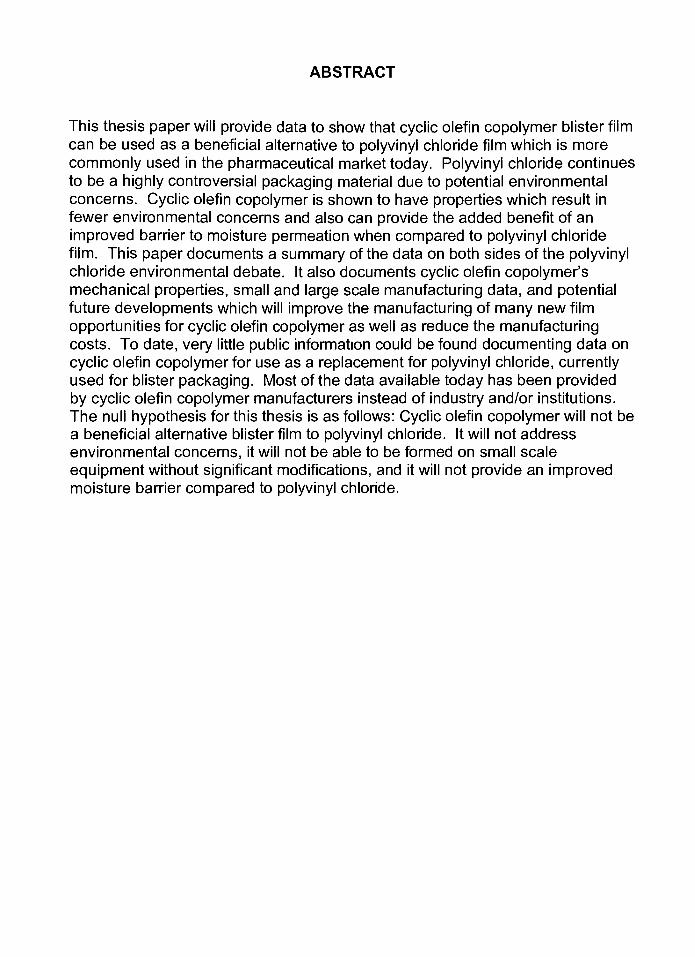
ABSTRACT
This thesis paper will provide data to show that cyclic olefin copolymer blister film
can be used as a beneficial alternative to polyvinyl chloride film which is more
commonly used in the pharmaceutical market today. Polyvinyl chloride continues
to be a highly controversial packaging material due to potential environmental
concerns. Cyclic olefin copolymer is shown to have properties which result in
fewer environmental concerns and also can provide the added benefit of an
improved barrier to moisture permeation when compared to polyvinyl chloride
film. This paper documents a summary of the data on both sides of the polyvinyl
chloride environmental debate. It also documents cyclic olefin copolymer's
mechanical properties, small and large scale manufacturing data, and potential
future developments which will improve the manufacturing of many new film
opportunities for cyclic olefin copolymer as well as reduce the manufacturing
costs. To date, very little public information could be found documenting data on
cyclic olefin copolymer for use as a replacement for polyvinyl chloride, currently
used for blister packaging. Most of the data available today has been provided
by cyclic olefin copolymer manufacturers instead of industry and/or institutions.
The null hypothesis for this thesis is as follows: Cyclic olefin copolymer will not be
a beneficial alternative blister film to polyvinyl chloride. It will not address
environmental concerns, it will not be able to be formed on small scale
equipment without significant modifications, and it will not provide an improved
moisture barrier compared to polyvinyl chloride.

TABLE OF CONTENTS
Page#
Title Page
Certificate ofApproval
Copying Agreement
Acknowledgements
Dedication v
Abstract vi
Table of Contents vii
List of Tables viii
List of Figures ix
List ofAbbreviations x
Chapter 1 - The PVC Debate 11
Production Process 13
Utilization 15
Recycling 17
Landfill 18
Incineration 20
Chapter 2 -Cyclic Olefin Copolymer 24
History of COC Film 24
Potential Uses for COC 26
Advantages and Disadvantages of COC 27
COC Properties 30
Manufacturing Process and Environmental Impact 36
Future Improvements in COC Films 39
Chapter 3 - Blister Packaging Overview 41
History of Blister Packaging 41
Variations of Thermoforming 42
Blister Packaging Types 43
Blister Packaging Process Description 45
Typical Blister Packaging Materials 46
Chapter 4 - Experimental Packaging Line Trials 50
Testing Protocol 50
Test Results 56
COC/PVC Comparison Testing 62
Summary of Commercial Scale Qualitative Tests 65
Conclusion 68
References 69
Attachment #1 - COC MSDS Sheet
Attachment #2 - BlisterWall Thickness Test Method
Attachment #3 - Water Vapor Transmission Rate Test Method
VII

LIST OF TABLES
Page#
Table #1 Plastic Resin Development Timeline 25
Table #2 Other Properties for COC 35
Table#3 COC DOXVariables 54
Table #4 COC DOX Experimental Runs List 55
Table#5 COC Operating Range 57
Table #6 COC Test Run Conditions 57
Table #7 Seal Integrity Testing Results -COC 58
Table #8 Card Curl Testing Results - COC 58
Table #9 Thickness Ration Testing Results - COC 59
Table #10 Aluminum Foil Heat Seal Temperature Range 61
Table #11 Seal Integrity Testing Results - Various Al Foil Suppliers 61
Table #12 Card Curl Testing Results - Various Al Foil Suppliers 62
Table #1 3 Small Cavity PVC & COC Operating Window 63
Table #1 4 Large Cavity PVC & COC Operating Window 64
Table#15 COC & PVC WVTR Comparison 65
VIM

LIST OF FIGURES
Page#
Figure #1 Drawings of Mono, Laminate, and Coated PVC Film Structures. ..11
Figure #1 Reprint of Drawings ofMono, Laminate, etc 48
Figure #2 Tg vs. Norbornene - COC 8007 31
Figure #3 COC MVTR vs. Temperature and Humidity - COC 8007 33
Figure #4 COC Production Process 37
Figure #5 Picture of Typical Blister Cards 41
Figure #6 Typical Small Scale Blister Machine 47
Figure #7 Drawings of PP, Cold-Formed Al, and COC Film Structures 49
Figure #8 Picture of Card Curl Measurement 54
IX
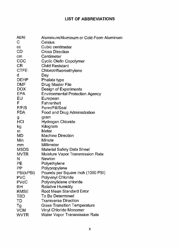
LIST OF ABBREVIATIONS
AI/AI Aluminum/Aluminum or Cold-Form Aluminum
C Celsius
cc Cubic centimeter
CD Cross Direction
cm Centimeter
COC Cyclic Olefin Copolymer
CR Child Resistant
CTFE Chlorotrifluoroethylene
d DayDEHP Phalate type
DMF Drug Master File
DOX Design of Experiments
EPA Environmental Protection AgencyEU European
F Fahrenheit
F/F/S Form/Fill/Seal
FDA Food and Drug Administration
g gram
HCI Hydrogen Chloride
kg Kilogram
m Meter
MD Machine Direction
Min Minute
mm Millimeter
MSDS Material Safety Data Sheet
MVTR Moisture Vapor Transmission Rate
N Newton
PE Polyethylene
PP Polypropylene
PSI(kPSI) Pounds per Square Inch (1000 PSI)PVC Polyvinyl Chloride
PVdC Polyvinylidene chloride
RH Relative HumidityRMSE Root Mean Standard Error
TBD To Be Determined
TD Transverse Direction
Tg Glass Transition Temperature
VCM Vinyl Chloride Monomer
WVTR Water Vapor Transmission Rate
THE PVC DEBATE
Polyvinyl chloride (PVC) is a polymer that was developed in the 1930's and today
is manufactured into several of the most widely used plastic films for blister
packages in the healthcare industry. In 1997 4.6% of the total quantity of plastic
sold was PVC. This PVC sales figure equated to 14 billion pounds of material
sold. Seven percent of the PVC sold was utilized in the packaging industry.
Within the packaging industry, 31% of the PVC is used in the medical field in
products such as blood bags, medical device packaging, and blisterpackages.1
PVC is typically used as a mono blister film, but it is also manufactured with other
materials laminated to the base film such as chlorotrifluoroethylene (CTFE trade
name ACLAR). In addition, PVC can be produced with coated materials adhered
to the base film such as polyvinylidene chloride (PVdC) to alter the films
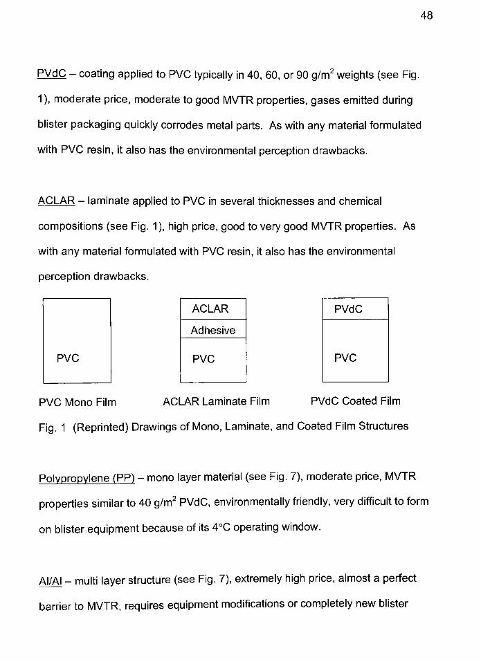
performance characteristics. (See Figure 1)
ACLAR
Adhesive
PVC
PVC Mono Film ACLAR Laminate Film PVdC Coated Film
Fig. 1 Drawings of Mono, Laminate, and Coated Film Structures
Two disadvantages of PVC material are that the monomer is relatively rigid and
11
12
that it is unstable when exposed to heat and light. When PVC is exposed to
heat and light there is a loss of chlorine (chlorine makes up 57% of the PVC
monomer), which converts to hydrogen chloride (HCI)gas.2
To correct these weaknesses, the PVC industry adds plasticizers to soften the
material and stabilizers to decrease the HCI off-gassing from commercial PVC
materials. The most common plasticizer types are phthalates (e.g. DEHP) which
are used for about 93% of the applications. Plasticizers can make up 15-60% of
the final PVC commercialproducts.3
The most common stabilizers historically
used were lead and cadmium. These additives softened the PVC products for
applications where rigid PVC was not desired orpractical.4
The controversy over PVC products, production processes, and disposal hazards
has been discussed for several years and is not likely to be settled in the near
future. Greenpeace and several other groups have declared PVC an
environmentally unfriendly material. In contrast, the PVC industry and other
interested parties have argued the material is as safe or safer than alternative
materials and the allegations against PVC are without merit.
Because PVC is so widely used in areas like food and medical packaging, water
pipes, blood bags, flooring materials, etc., understanding the material's safety
both now and for future generations continually draws attention around the world.
13
This section is intended to fairly present data on PVC currently available in the
public literature. The data is intended to equally represent both sides of the PVC
environmental debate without bias.
PRODUCTION PROCESS
Anti-PVC Argument
Environmental groups like Greenpeace have argued that both the production
process of PVC monomers and the finished PVC products are dangerous. The
most significant danger is documented to be the production of vinyl chloride
monomer (VCM), which is one of the primary components of the PVC polymer.
The vapors from this material are documented as carcinogenic and can produce
other harmful affects for workers. Greenpeace documents lung damage, spleen
damage, and angiosarcoma, a rare liver cancer, all as potential health risks for
workers in the PVC industry. They also claim phthalates are a likely cause of
testicularcancer.5
It is argued that the people living in communities where the PVC plants are
located could be subjected to dangerous fumes or dust given off by the
production plants during normal operation. There is also a concern of a
significant risk to the local communities in the event of a plant disaster such as a
fire or explosion.
14
During the production process, lead and cadmium are used as stabilizers in
some PVC film products to modify thefilms'
performance characteristics. Both
lead and cadmium are documented to be toxic and to act ascarcinogens.6
Pro-PVC Argument
The PVC industry has documented that the risk to their workers was an issue in
the past. Initially, the industry was not aware of the dangers of exposure to the
VCM monomer. Once the issue was discovered, it was immediately corrected.
Since this time, workers have shown no increase in any abnormal health risks.
The VCM vapors are reported to be contained during the production process and
do not exit the plant in any quantities that would be a threat to workers or the
localcommunities.7
Plant disasters are also a risk, but it has been documented that in one PVC
warehouse fire the levels of exposure to any local communities were well below
the acceptable limits. The dust from this warehouse fire settled on snow around
the warehouse. This PVC plant disaster during the winter season allowed the
only study of this type of exposure risk to be evaluated to date.8
Use of lead as a stabilizerwas completely stopped by the PVC industry some
time ago. Cadmium is still in use as a stabilizer in some PVC products, but is
planned to be completely phased out of production during 2001
15
The last point of argument by the PVC industry for the benefit of their production
process is the amount of energy required. PVC is reported to consume the least
amount of nonrenewable resources of any plastic and requires the least amount
of energy (about 50%) to manufacture PVC resin. Part of the reason for this
lower energy requirement is the chlorine component of the PVC polymer, which
is a naturalcatalyst.10
UTILIZATION
Anti-PVC Argument
Greenpeace has published three major arguments against the use of PVC for
safety concerns. First, they have provided data that the use of PVC materials
contributes to the amount of dangerous leachates that migrate out of the PVC
over time either during use or once the material has been placed into a landfill.
These leachates do not come from the PVC monomer, but rather the additives
used to manufacture and modify the plastic. These leachates end up in the
water system due to run off from thelandfill.11
Second, Greenpeace argues that PVC is a hazard in building and home fires.
They have stated that if the PVC material is burned toxic fumes and ash are
released. During fires, smoldering PVC gives off HCI gases that can be inhaled
by victims. This HCI gas combines with water in the lungs forming hydrochloric
acid causing severe burns to lung tissue.
16
Lastly, Greenpeace has argued that PVC gives off [unspecified] chemicals that
can cause "Sick Building Syndrome". This illness is a condition some people
experience in certain buildings caused from several possible factors.
Greenpeace argues that additives migrate out of PVC materials and become
airborne. These airborne additives can then affect buildinginhabitants.13
Pro-PVC Argument
In contrast, the PVC industry argues that there has been no evidence of
leachates from PVC in landfills. In fact, they argue some liners used in landfills
to contain the waste and leachates are made fromPVC.14
The PVC industry also has done extensive tests to show PVC actually stops fires
and can help to save lives in the event of home or building fires. PVC is very
difficult to burn and will not burn on its own without something else providing the
flamesource.15
Lastly, the PVC industry states that there is absolutely no scientific proof that
PVC contributes to Sick Building Syndrome. The PVC industry argues this is just
a scare tactic Greenpeace has used in their attack onPVC.16
17
RECYCLING
Anti-PVC Argument
The Commission of the European Communities held a meeting on 23 October
2000 to discuss the PVC debate. One of the topics discussed was recycling of
PVC. The current quantity of recycled PVC is negligible, about 0.2% in the
United States in 1992, due to the difficult process required for recycling this
material. There is also a negative feeling by the recycling industry concerning
the potential that PVC could get mixed in with the rest of the plastic types and
ruin their entire recycling batch. This negative concern stems from the fact that
PVC plastic can potentially char at temperatures needed to melt polyethylene
(PE) plastic. One recycling company stated one PVC bottle mixed in with 30,000
PE bottles was enough to ruin the entirebatch.18
The second piece to the recycling argument against PVC is the financial
practicality of this process. The reason more recycling of PVC does not occur is
that the financial benefits are not available for recycling companies. The prices
for virgin PVC resin are very low and the types of products that can be made
from recycled PVC are low quality, low priceproducts.19
Pro-PVC Argument
The PVC industry argues that the sorting process needs to be improved by the
recycling companies. This in turn would make the issues of mixing plastic resin
types less of a concern. The PVC industry also argues that new and improved
18
recycling processes for PVC are in development. One process called
"DissolutionPrecipitation"
would even allow the recycling of PVC used in blister
packages, with foil heat sealed to the plastic, to be fullyrecovered.20
The PVC industry also argues that several important products are made from
recycled PVC and the more products that use the recycled PVC, the greater the
demand will be for PVC recycling. As the demand for recycled PVC rises, the
prices the recycling companies can get for PVC will also rise. The PVC industry
argues that local governments have a responsibility to put legislation in place to
mandate certain recycling quantities of PVC. They believe this legislation could
allow sufficient quantities of PVC to be available for use in many new commercial
products.21
LANDFILL
Anti-PVC Argument
Greenpeace has published two significant arguments against the practice of
placing PVC waste in a landfill. First, as mentioned above, they have provided
data that the use of PVC material contributes to the amount of dangerous
leachates that migrate out of the PVC over time, either during use or once the
material has been placed into a landfill. These leachates do not come from the
PVC monomer, but rather the additives that are used to manufacture and modify
the plastic. These leachates end up in the water system due to run off from the
landfill.22
19
Second, Greenpeace has published data that landfill disasters pose significant
risk to firefighters and communities near landfill sites. Landfill disasters typically
occur when a portion of the landfill catches fire. PVC within the landfill is then
burned and dangerous fumes and soot are created. Unfortunately, not all landfill
disasters are accidents. Some landfill managers use this as a practice to reduce
the quantity ofwaste and in the process, waste materials are burned incorrectly
and pose a threat to our environment. The United States Environmental
Protection Agency (EPA) reports one-fifth of the total dioxin emissions released
into the air is due to landfillfires.23
Pro-PVC Argument
As stated above, the PVC industry argues that there has been no evidence of
leachates from PVC in landfills. In fact, they argue some liners used in landfills
to contain the waste and leachates are made fromPVC.24
Several articles documented that the PVC industry recognizes improper burning
of PVC can pose a threat to the environment. They agree tougher legislation
needs to be put in place for landfill managers who illegally burn theirwaste. The
PVC industry also agrees that more effort needs to be used to prevent accidental
fires at landfill sites.
20
INCINERATION
Anti-PVC Argument
Arguments against PVC incineration have been made by both Greenpeace and
by European legislators. The three main arguments against PVC incineration
have focused on: 1.)dioxins omitted during incineration, 2.) the safety of the
neighboring communities, and 3.) the true amount of waste reduction that occurs
as a result of incinerating PVC refuse.
"Dioxin is a shorthand name given to ... a family of 75 different chemical
compounds with a similar chemical structure and set of biological effects...".
These effects can result in significant disruptions to the endocrine system of
animals andhumans.25
Greenpeace and others argue that significant quantities
of dioxins are given off during the incineration of PVC waste. Dioxins are
released into the environment where they bio-accumulate in fatty tissues of both
animals and humans. Some studies have been done to show a link between
dioxins and several medical conditions including cancer, immune system
disorders, reproduction complications, and developmental problems. This may
pose a significant risk to workers, people who live near incineration facilities, and
other communities around the world where trace residue has been found. In
addition to dioxins, HCI gas is given off during the incineration process, which is
also a risk to workers and neighborhoodinhabitants.26
21
The last argument against the incineration of PVC waste is the true quantity of
refuse reduction that occurs from this process. Various salt forms are used as
"scrubbing"
agents to remove the HCI gas, dioxins etc. Once these neutralization
salts are exhausted they must be treated as hazardous waste and disposed of in
special landfills. The amount of salt generated during PVC incineration can be
greater than the original quantity of PVC incinerated. One kg. of PVC waste
typically generates between 0.4-3 kg. of contaminated salt. Because of this
quantity of waste generated, it is argued that incinerating PVC is a ridiculous
practice forwastereduction.27, 28
Pro-PVC Argument
Articles have been written by both the PVC industry and the New York Energy
Authority that argue PVC waste does not contribute to the amount of dioxin
released byincinerators.29
Any waste containing chlorine, and a few other key
ingredients such as copper, which acts as a catalyst, results in the formation of
dioxins. There have been several studies performed, which show no correlation
between the amount of PVC in the incinerator and the formation of dioxins.
These studies have shown almost any source of chlorine (including paper
products, table salt, and food waste) can produce dioxins and even if PVC is
completely eliminated this would not affect dioxinproduction.30
About 95% of
consumer products are reported to be made using chlorine in somefashion.31
22
Dioxins, which are formed during natural forest fires, are reported to be a
significant contributor of dioxin deposits. These natural deposits are found in the
soil, on blades of grass, and on leaves. The quantities of dioxins just below the
surface of the soil are reported to be seven times the allowable limits set by
governmentalagencies.32
There have also been several studies that have shown incineration temperature
and the amount of oxygen present is critical in the amount of dioxin that is formed
during incineration. If temperatures are properly adjusted and airflow is tightly
controlled, the levels of dioxins produced during incineration arenegligible.33
In
reality this is very difficult to achieve during normal incinerator operation.
"In their 1994 reassessment of dioxin exposure, [the] EPA reviewed the
Greenpeace data, but ultimately concluded that insufficient emissions data were
available to make an independent evaluation of the claim that PVC
manufacturing is a significant source of dioxinemissions."34
There have also been studies evaluating the amount of dioxins released from
incinerators which were not tightly controlled for temperature and oxygen. These
dioxin emission values have been compared to the amount of dioxins produced
by wood burning stoves and back yard "barrelburning"
of household waste. The
average commercial incinerator releases less dioxin waste burning trash from
37,000 non-recycling households, or trash from 121,000 recycling households,
23
than is generated from a single fire where a household has burned their trash in
a "barrelburning"
process. The PVC industry has argued that if dioxins are a
real concern, environmentalists should focus on large sources of dioxin waste
such as wood burning stoves and families who burn their owntrash.35
They
believe this is the greater risk for communities and neighborhoods well being.
Belgium, the United Kingdom, the United States, Canada, Netherlands, and
Sweden all report that PVC currently contributes only 0.1% of the dioxins to our
environment.36
The PVC industry also argues that burning trash does significantly reduce waste.
They believe the claims made by Greenpeace, concerning the amount of waste
from incineration scrubbers equaling the amount of trash burned, is another
scare tactic.
CYCLIC OLEFIN COPOLYMER
Cyclic Olefin Copolymer (COC) is a plastic resin recently developed for use in
several commercial applications. The trade name for the COC resin is TOPAS
resin.
History of COC Film
Cyclic olefin polymers have been evaluated by the plastics industry for many
years. Historically COC polymers were not commercially manufactured due to
the high cost of production and a limited ability to produce satisfactory quality
monomers. The recent development of metallocene catalysts changed these
production issues and made commercial production of COC possible and
affordable.37
Below is a listing (Table 1 ) of some of the plastic polymers developed along with
the year of discovery. This table is listed to give a complete history leading up to,
and including, the development of the modern COC formulations.
24
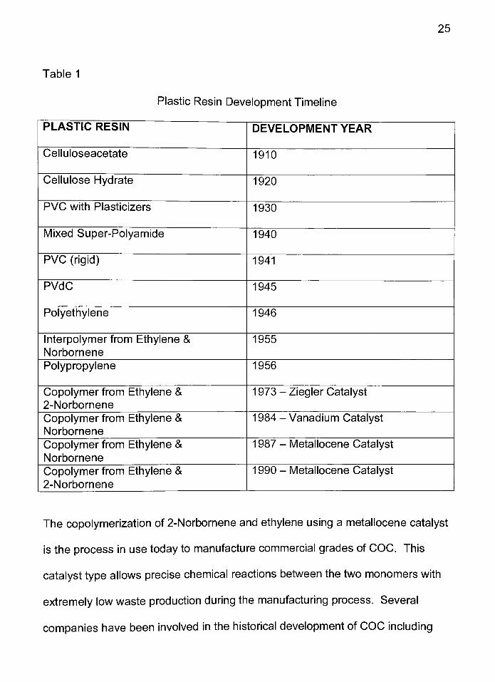
25
Table 1
Plastic Resin Development Timeline
PLASTIC RESIN DEVELOPMENT YEAR
Celluloseacetate 1910
Cellulose Hydrate 1920
PVC with Plasticizers 1930
Mixed Super-Polyamide 1940
PVC (rigid) 1941
PVdC 1945
Polyethylene 1946
Interpolymerfrom Ethylene &
Norbomene
1955
Polypropylene 1956
Copolymer from Ethylene &
2-Norbornene
1 973 -Ziegler Catalyst
Copolymer from Ethylene &
Norbornene
1 984 - Vanadium Catalyst
Copolymer from Ethylene &
Norbornene
1 987 - Metallocene Catalyst
Copolymer from Ethylene &
2-Norbornene
1990 - Metallocene Catalyst
The copolymerization of 2-Norbornene and ethylene using a metallocene catalyst
is the process in use today to manufacture commercial grades of COC. This
catalyst type allows precise chemical reactions between the two monomers with
extremely low waste production during the manufacturing process. Several
companies have been involved in the historical development of COC including
26
DuPont, Montecatini, VEB Leuna, Mitsui Petrochemicals, and Ticona Technical
Polymers (formerly Hoechst AG).38
In Q3 2000, Ticona Technical polymers announced the opening of a 30,000 ton
per year COC resin manufacturing site in Oberhausen, Germany. For the first
time COC resin was available in large quantities for commercial use.39
Potential Uses for COC
The COC manufacturers anticipate three main uses for the base resin. The resin
has been targeted for powdery resins, injection molding, and films.
The powdery resin classification includes using COC as a toner-binder resin
powder (as typically used in copier machines, faxes, and printers). It is also
marketed as a powder coating.
Injection molding includes optical applications such as media storage items and
lenses for eyeglasses and CD players. This category also includes medical
applications such as barrels for syringes, plastic vials, and plastic-ware for
laboratories. The COC resin can also be used for engineering applications such
as car parts and other small injection molded devices.
Lastly, COC is used in film applications. Film applications are split into thin
gauge films (4-30 microns) and heavy gauge films (30-600 microns). Thin gauge
27
films are used in capacitors, shrink films, and wrappers for cough drops and
candy. Heavy gauge films are used in thermoforming operations for
pharmaceutical and over the counter (OTC) products. The COC film can also be
thermoformed for other larger packaging applications both inside and outside the
healthcareindustry.40
While several COC resin types can be used for multiple applications both inside
and outside of the packaging area, this paper will only focus on the 8007 resin
grade for pharmaceutical films.
Advantages and Disadvantages of COC
As with any type of plastic polymer, its chemical structure makes the resin well
suited for some applications and poorly suited for others. Several items are
listed within this section that are both positive and negative attributes of the COC
plastic polymer for blister packaging.
28
COCBenefits41
Good moisture vapor transmission rate (MVTR) and absorption properties
Excellent transparency
Good stiffness
Excellent thermoforming characteristics
Short cycle time
Low machine-direction (MD) and cross-direction (CD) shrinkage
Good elongation at break
Low density
Typically can be run on existing equipment without modifications
High resin production yield
Low environmental risk (discussed on page 36)
The MVTR rates for COC are comparable to a 60 gram PVdC material. This
property helps to keep moisture out of a blister card and helps improve the
product shelf life in high humidity regions. The transparency, or clarity, ensures
the blister card is aesthetically pleasing to the end use customers and that the
product maintains a "pristinepharmaceutical"
look. The stiffness characteristic
helps the package withstand distribution, it helps the blister cavities to stay rigid,
and keeps the cavities in the correct shape when consumers carry the finished
blister card with them in a pocket or purse. The good thermoforming, shrinkage,
and short cycle time characteristics ensure the COC blister cards can be easily
29
formed with acceptable quality and low cost compared to other similar plastic
materials. Elongation at break ensures the material can withstand the pressures
of a production thermoforming operation. This includes the pressures during the
forming process and when pressures are applied to the film to pull it through the
machine. Lastly, the density is important to keep the COC costs down. Because
the density of the material is low, the yield of the COC resin is high.
COC Disadvantages
Cost
Poor chemical resistance to fats and oils
Poor chemical resistance to aliphatic solvents.
Cost is variable but typically it is similar to a 60-90 gram PVdC material. This
cost; however, is currently over 4 times higher than a standard PVC material.
Due to the small quantity of COC used for each blister card, this increase only
amounts to approximately a US $0,015 increase in cost for an average sized
blister card. Resistance to fats and oils is an issue for COC. This limitation is the
reason why the COC finished film must be a tri-layer material with some other
material on the outside of the COC core (see Figure #7). Even the oils on
people's hands are enough to cause the COC resin to stress-crack over time.
The incompatibility with aliphatic solvents would mean that COC material would
not be a good choice for products containing solvents such as hexane or
toluene.42
30
COC Properties
The following section gives some of the most important properties for COC resin
#8007 as it relates to blister packaging. As previously noted the COC resin
grade #8007 is used for pharmaceutical grade film applications. Several other
COC resin types exist with varied properties for multiple applications outside of
the scope of this paper. While it would be interesting to compare these
properties in a side-by-side comparison to PVC resin/film, this is not practical.
There are multiple PVC resin/film types suitable for use in several different blister
packaging situations. Since each supplier's commercial resin/film line-up varies
in several properties it is a better comparison to evaluate the formability of the
materials as shown in the next chapter of this paper.
Glass Transition Temperature
The glass transition temperature (Tg) for COC can be varied to achieve a range
of 80-1 80C. By adjustment of the percentage of norbornene the Tg is varied
(see Figure #2). The glass transition temperature must be balanced with the
amount of flexibility required for the final end use product, as Tg is inversely
proportional to flexibility. The norbornene stiffens the main polymer chain and
prevents crystallization of the polymer.

31
250
20
Topa;;
>roducts
4 1) :in fit.
moI-% norbornene
Figure 2 - Tg vs. Norbornene - COC 8007
Elongation at Break
Elongation at break is the percentage of stretch the material can withstand before
failure occurs. For the 8007 COC material the range is 5-10%.
Moisture Vapor Transmission Rate
Moisture Vapor Transmission Rate (MVTR), orWater Vapor Transmission Rate
(WVTR) as it is sometimes called, is the amount of moisture that passes through
a material. This rate varies based on the temperature and humidity at which the
test is conducted. Thegraph43
shown in Figure 3 lists permeation rates for
various thicknesses of flat COC films at different temperature and humidity
settings. The changes in film thickness are achieved by variations of the middle
32
COC material layer. Both of the outside PP layer thicknesses remain constant
(30 microns) for the various COC film products exhibited. It should also be noted
that moisture absorption is low for COC. All COC resin grades including 8007
have an absorption value of less than 0.01%.

COC MVTR Results
33
0 30-140-30
30-190-30
D 30-240-30
D 30-300-30
23C/85% 37.8C/75% 37.8C/90% 40C/90%
Temperature / Humidity Settings
40C/100%
Figure 3 - COC MVTR vs. Temperature and Humidity
COC 8007 Resin
34
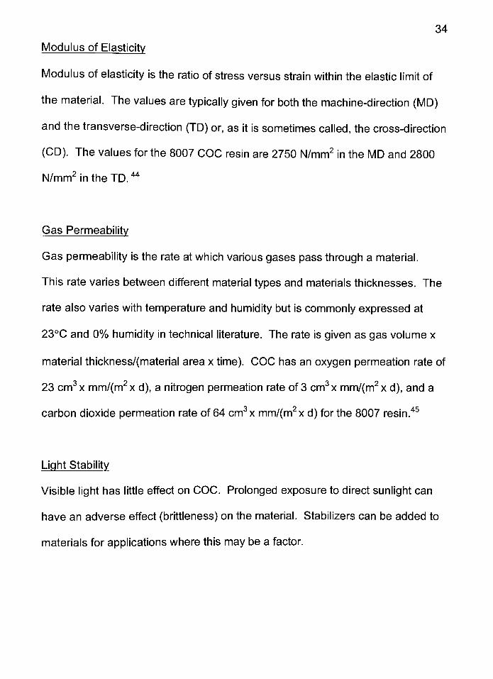
Modulus of Elasticity
Modulus of elasticity is the ratio of stress versus strain within the elastic limit of
the material. The values are typically given for both the machine-direction (MD)
and the transverse-direction (TD) or, as it is sometimes called, the cross-direction
(CD). The values for the 8007 COC resin are 2750N/mm2
in the MD and 2800
N/mm2
in the TD.44
Gas Permeability
Gas permeability is the rate at which various gases pass through a material.
This rate varies between different material types and materials thicknesses. The
rate also varies with temperature and humidity but is commonly expressed at
23C and 0% humidity in technical literature. The rate is given as gas volume x
material thickness/(material area x time). COC has an oxygen permeation rate of
23 cm3x mm/(m2x d), a nitrogen permeation rate of 3 cm3x mm/(m2x d), and a
carbon dioxide permeation rate of 64 cm3x mm/(m2x d) for the 8007resin.45
Light Stability
Visible light has little effect on COC. Prolonged exposure to direct sunlight can
have an adverse effect (brittleness) on the material. Stabilizers can be added to
materials for applications where this may be a factor.
35
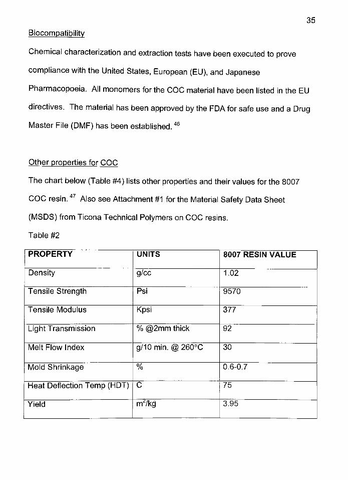
Biocompatibilitv
Chemical characterization and extraction tests have been executed to prove
compliance with the United States, European (EU), and Japanese
Pharmacopoeia. All monomers for the COC material have been listed in the EU
directives. The material has been approved by the FDA for safe use and a Drug
Master File (DMF) has been established.46
Other properties for COC
The chart below (Table #4) lists other properties and their values for the 8007
COC resin.47
Also see Attachment #1 for the Material Safety Data Sheet
(MSDS) from Ticona Technical Polymers on COC resins.
Table #2
PROPERTY UNITS 8007 RESIN VALUE
Density g/cc 1.02
Tensile Strength Psi 9570
Tensile Modulus Kpsi 377
Light Transmission % @2mm thick 92
Melt Flow Index g/10min. @ 260C 30
Mold Shrinkage % 0.6-0.7
Heat Deflection Temp (HDT) C 75
Yield m^/kg 3.95
36
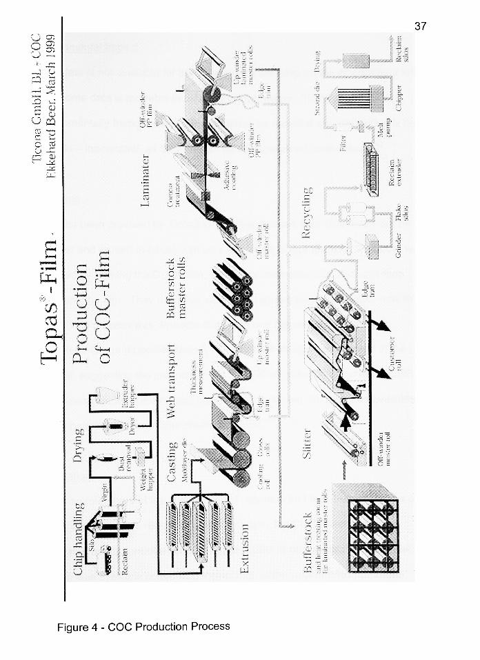
Manufacturing Process and Environmental Impact
"COC's are polymers based on hydrocarbons, whose raw materials come from
petrochemicals (naphtha cracker). Therefore they are environmentally friendly,
recyclable, and do not emit toxicgases."48
This section will focus on the
manufacturing process and the environmental aspects of the COC resin. The
manufacturing process is explained through a diagram provided by Ticona
GmbH, one of the COC resin manufacturers. The environmental details for COC
are listed below. Because COC is a new polymer, many of the long-term affects
COC may have on the environment are yet to be determined.
Manufacturing Process
"In the manufacturing process, the cycloolefin dicyclopentadiene is first split into
cyclopentadiene, which is then reacted with ethylene into norbornene. Co-
polymerization of the norbornene with additional ethylene then results in
cycloolefincopolymers."49
See the diagram on the following page (Figure 4) for
more production details.
u CT:
,"-*i _T^
L_)CT5
S_T"
*
1 <-
J U
CQ 01
i ^,
. .-
i
05
U ca
$2 "p
o Kj
i j . ,
'. C____
,^ILL'
37
e^*.. .-,. NMM
Tt ,
...
'
o
y I
p./___
__
r?
O
pa
U . p 1
;.., ..,....;..J
5^-
s
_____^
k-fi_,.^*l
Figure 4 - COC Production Process
38
Environmental Impact
While data is not available for the affects COC will have on the environment long-
term, some data is available in publications for review. "[COC's] are
environmentally friendly, since they can either be recycled or - where that is not
sensible - incinerated, as they release no toxic gases oncombustion."49
Recycling
Data has been provided by Ticona GmbH that showed their COC resin can be
recycled and reused in-house with very little change in properties. This data was
collected by forming the COC resin, turning the resin into COC film, and then
shredding the film. They used this shredded (regrind) material to make new film
stock. This process was repeated four times and several properties were
evaluated. Of the properties tested, no significant changes were noted in the
material, suggesting the potential exists for COC recycling opportunities. COC
can be recycled with other mixed olefins with no issues. No data was available
on compatibility with any other plastic materials.50
Incineration
COC's are members of the olefin family of polymers and their building blocks are
carbon and hydrogen. Because of this structure, the COC material, when
incinerated under controlled conditions, degrades to carbon dioxide and water.
No data was available concerning incineration under uncontrolled conditions.
39
Landfill
While no long-term data is available on the safety of landfilled COC there have
been a few data points evaluated to predict potential landfill hazards. COC
contains no heavy metals. COC contains typical processing aids and additives
and there is no reason to believe it cannot be safely landfilled.
Future Improvements in COC Films
Several improvements are under research and development by commercial film
manufacturers. No changes are planned for the resin itself but there are
opportunities for improvements in the finished film materials.
The first development effort is to help make the finished film less expensive,
easier to manufacture, and reduce the number of layers in the final film structure.
Today COC is a 5-layer material. The structure is made from 30 microns of PP,
an adhesive layer, 190-300 microns of COC, an adhesive layer, and 30 microns
of PP (see Figure #7). The COC film and the PP film layers are cast separately
and then bonded together in the lamination process. This process is necessary
because PP and COC do not stick together well enough for commercial use of
the finished film. Research is underway to allow the PP and COC to be co-
extruded together either as a 5-layer structure or even farther down the road as a
3-layer structure, eliminating the adhesive layers altogether.

40
The second development is the addition of other existing films, resins, and
coatings to COC to improve the film properties. Most of these additions will be to
improve the COC materials barrier properties against gases (e.g. oxygen,
nitrogen, carbon dioxide) and decrease moisture permeation rates.
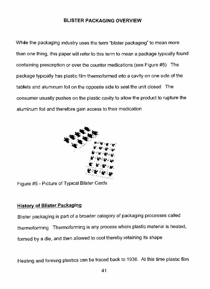
BLISTER PACKAGING OVERVIEW
While the packaging industry uses the term "blisterpackaging"
to mean more
than one thing, this paper will refer to this term to mean a package typically found
containing prescription or over the counter medications (see Figure #5). The
package typically has plastic film thermoformed into a cavity on one side of the
tablets and aluminum foil on the opposite side to seal the unit closed. The
consumer usually pushes on the plastic cavity to allow the product to rupture the
aluminum foil and therefore gain access to their medication.
;-
.~"tt.
Figure #5 - Picture of Typical Blister Cards
History of Blister Packaging
Blister packaging is part of a broader category of packaging processes called
thermoforming. Thermoforming is any process where plastic material is heated,
formed by a die, and then allowed to cool thereby retaining its shape.
Heating and forming plastics can be traced back to 1936. At this time plastic film
41
42
was used in France to shrink wrap meat. In World War II plastic sheets were
formed into topographical maps using the thermoforming process described
above.
It was not until the 1950's that thermoforming started to catch on and become
more commonly used. Today there are between 5-10 billion thermoformed
packages produced eachyear.51
Variations of Thermoforming
All three types of thermoforming use the same basic heating, forming, and
cooling concepts. Each of the three variations are briefly discussed below.
Skin Packaging
Skin packaging is a process where a thin plastic film is heated and then typically
placed around both a product and a paperboard backing material. While the
plastic is still soft, a vacuum is used to draw the air out of the package which
forces the plastic to secure the product to the paperboard backing. This process
is typically used for products that will be displayed on pegboard in the retail
stores.
Thermoforming
The term thermoforming can be used in the broad sense, as above, or as a term
used to describe a specific process. This process is where thick gauge plastic
43
film is heated, typically with radiant heat, and then formed using a male or female
mold with vacuum, air pressure, and/or mechanical pressure. This process is
typically used to form plastic cups and tubs.
Blister Packaging
Blister packaging is where thick gauge materials are heated, typically with
contact heat, and the soft plastic is drawn into female molds to shape small
cavities with vacuum, air pressure, and/or mechanical pressure. This process is
typically used to package healthcare products for over the counter and
pharmaceutical products. Usually aluminum foil is heat sealed to the film to
create a backing on thepackage.51
Blister Packaging Types
Film/Foil
The most common blister package type manufactured is made from
thermoformed plastic cavities on one side of the product and a flat aluminum foil
sealed to the film, which encloses the product within the package. This top-sheet
is typically referred to as the "lidstock". The aluminum foil is typically printed and
may contain paper in thestructure for ease of readability/printing or improved
child-resistant (CR) properties. The portion of the lidstock that faces the film
contains a heat seal coating that allows the film and foil material to be sealed
together by the blister packagingequipment.
44
Film/Film
The second type of blister package contains the same plastic structure for the
base material but the lidstock is made from another plastic film instead of
aluminum foil. This film material is typically highly oriented which allows the
tablets to be"popped"
through the backing material when ready for use. This film
can be printed but typically is not available in a CR structure. The advantage of
this structure is that it is perceived to be more environmentally friendly. The
disadvantage for this structure type is that the film lets significantly more moisture
pass through it than the aluminum foil structures.
Foil/Foil
Foil/foil or "cold formfoil"
uses a typical lidstock material in either a CR or non-
CR version. The main difference in this material is that the base material is also
made from mostly aluminum foil. The base material is much thicker than the
lidstock material and typically contains a thin layer of plastic that allows the
lidstock to be heat sealed to it. The plastic also allows the material to be
"stretched"
into the final shape without rupturing the aluminum foil. The cavities
needed to house the product are not formed by heating the material and blowing
the warmed material into female molds. Instead, the cavity shapes are made by
mechanically forming the material into the required shape. A male mechanical
plug is used to bend and slightly stretch the material to the final shape. The
advantage of this structure is that it is almost completely moisture resistant. The
45
disadvantages are material cost, modifications required to existing equipment,
and the line typically has to be run at a slower speed than with a film structure52
Blister Packaging Process Description
Overview - This section describes a typical commercial scale form/fill/seal (FFS)
operation. Several variations are offered by some of the many machinery
manufacturers but for the purposes of this paper, the most common process has
been described. Typically, once most blister packages are manufactured using
the FFS process they are inserted into a carton for distribution. See the picture
on page 47 (Figure #6) corresponding to each of the following eight sections.
1 . Preheating: preheat plates, located on both sides of the film web, contact the
film and transfer the appropriate amount of heat to soften the plastic film.
2. Cavity forming: blister cavities are formed out of the warmed film via air
pressure and/or mechanical plugs. The air pressure blows the film to fully
form the cavity.
3. Product filling: the product is filled into the formed cavities via a dedicated or
flood feeder system. Several factors can determine if dedicated (each tablet
is placed inside a specific cavity) or flood feeding (tablets pushed over
cavities with brushes or paddles) is the best method for a particular product
including line speed, shape of tablet, and tablet friability.
46
4. Tablet Inspection: a vision system is typically used to inspect the filled cavities
for any missing or broken tablets. Rejected cards are automatically removed
from the line after the punching station. Some vision systems can also detect
colors of tablets to differentiate between strengths of the same product and
help ensure a mix-up does not occur.
5. Printing/Coding: the lidding foil may be printed and/or coded with all of the
appropriate information including the control number and expiration date via
an on-line printer.
6. Heat sealing: the lidding foil is sealed to the film by a heated plate which
presses the film and foil together for the appropriate amount of time to
achieve a good seal.
7. Punching: the cards are cut through to the final card shape and punched out
of the film/foil web.
8. Card transfer: rejected cards are dropped from the line and accepted cards
move to the secondary packaging operation. The equipment typically
punches out two or more blister cards at a time and may have the ability to
reject only the selected cardson some machines.

47
Figure #6 - Typical Small Scale Blister Machine
From this point, leaflets may be added to the collated blister cards before the
appropriate numbers are placed into cartons. Cartons may pass overcheck-
weigher equipment before being placed into a shipping case and then palletized
for transportation.
Typical Blister Packaging Materials
The materials listed below are the most common blister packaging materials
used in the industry. Some basic details are given about each of the structures
and when they are appropriately used in the packaging industry.
PVC - mono layer material (see Fig. 1 reprinted below), poor MVTR, cheap,
perceived as environmentally unfriendly, most commonly used blister material.
48
PVdC -
coating applied to PVC typically in 40, 60, or 90g/m2
weights (see Fig.
1), moderate price, moderate to good MVTR properties, gases emitted during
blister packaging quickly corrodes metal parts. As with any material formulated
with PVC resin, it also has the environmental perception drawbacks.
ACLAR - laminate applied to PVC in several thicknesses and chemical
compositions (see Fig. 1), high price, good to very good MVTR properties. As
with any material formulated with PVC resin, it also has the environmental
perception drawbacks.
PVC Mono Film ACLAR Laminate Film PVdC Coated Film
Fig. 1 (Reprinted) Drawings of Mono, Laminate, and Coated Film Structures
Polypropylene (PP) - mono layer material (see Fig. 7), moderate price, MVTR
properties similar to 40g/m2
PVdC, environmentally friendly, very difficult to form
on blister equipment because of its 4C operating window.
AI/AI - multi layer structure (see Fig. 7), extremely high price, almost a perfect
barrier to MVTR, requires equipment modifications or completely new blister
49
packaging equipment, if cavities are dented during handling they stay dented
(aesthetic concern).
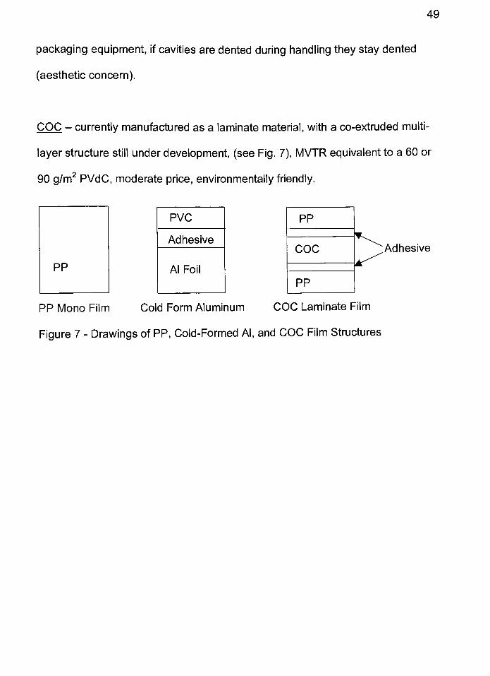
COC -
currently manufactured as a laminate material, with a co-extruded multi
layer structure still under development, (see Fig. 7), MVTR equivalent to a 60 or
90g/m2
PVdC, moderate price, environmentally friendly.
PP
COC
PP
Adhesive
PP Mono Film Cold Form Aluminum COC Laminate Film
Figure 7 - Drawings of PP, Cold-Formed Al, and COC Film Structures
COC EXPERIMENTAL PACKAGING LINE TRIALS
To ensure COC material could be run on blister packaging equipment without
any significant issues or equipment modifications, line trials were run on
development and commercial scale equipment. The commercial scale work has
been for information purposes only and no significant amount of testing or
statistical data evaluation has been completed. The COC testing effort at
development scale, however, has been completed with the intent of comparing
COC to PVC material and to ensure all development scale differences and
success criteria were understood and quantified.
This section will document the COC development testing protocol, data
summary, a comparison between COC and PVC, and commercial scale data
collected to show COC is a potential replacement for PVC for blister packaging.
COC DEVELOPMENT SCALE TESTING PROTOCOL
Below is a modified version of the original protocol executed to test the COC
blister film on development scale equipment. The details of the protocol are
given below and are still documented in the original future tense writing style.
Protocol for Testing Cyclic Olefin Copolymer (COC) Blister Film Material
Purpose:
This protocol outlines a plan to test COC blister film and multiple lidding material
50
51
options for potential use with future pharmaceutical products. The lidding
materials tested will be from several material suppliers.
Objective:
The objectives of this protocol are to:
1.)Form blister cavities from the COC blister material on a development scale
Klockner EAS II. Use common range finding techniques to determine the
operating window which will form good blister cavities and run a small design of
experiments (DOX) to find the best settings for the COC material. The blister
cards will be evaluated for thickness, card curl, and seal integrity to find the best
settings. WVTR testing will be performed on the films that had the best results
from the previous tests.
2.) Test various types of lidding materials for potential use with the COC material.
These materials include aluminum foil options from several vendors that contain
a heat seal coating compatible with PP (the outside layer material for COC).
3.) Determine if any modifications are needed to the Klockner EAS II machine to
optimize the production of the COC blister cards.
Eguipment and Materials:
Klockner EAS II Development Scale Blister Machine
Upper Form Tool #C35978
52
Lower Form Tool #B35976
Sealing Tool #B25561
Klockner, 300 micron, COC TOPAS film, #8007
Hueck, 20 Micron, push-through foil, Vendor Spec #AI220CHM
Lawson Mardon, 20 micron, push-through foil, Vendor Spec #1 12-2077E
Teich, 20 micron, push-through foil, seals to PETG and PP, Vendor Spec
#PAPH-99-1 01 -KAAB/01 7
Magna Mike Thickness Gauge
Bell Jar, Vacuum Pump, and Methyl Blue Dye
Ruler
MOCON Moisture Permeation Rate Tester
Procedure:
Objective #1
The COC material will be placed on the Klockner machine and the high and low
settings for the critical variables will be determined before starting the DOX runs.
Critical variables for this testing are defined as forming temperature, sealing
temperature, and forming pressure. Once the high and low settings are found for
each of these critical variables a23
full factorial DOX with a center point will be
executed using the set of runs listed below. The machine will be run for about 12
minutes during each of the experimental runs to allow the machine to "warmup"
(~2 minutes) and to allow the operators to collect 65 samples.
53
Measurement Method
The method used to test the blister cards for thickness can be found in
Attachment #2 (Method Number PkgDev101 - BlisterWall Thickness Test).
The method used to test the blister cards for seal integrity can be found in ASTM
Method D 3078-94 Determination of Leaks in Flexible Packaging by Bubble
Emission.
The method used to test the blister cards forWVTR can be found in Attachment
#3 (Method Number PkgDev121 - Water Vapor Transmission Rate (WVTR) -
Blisters).
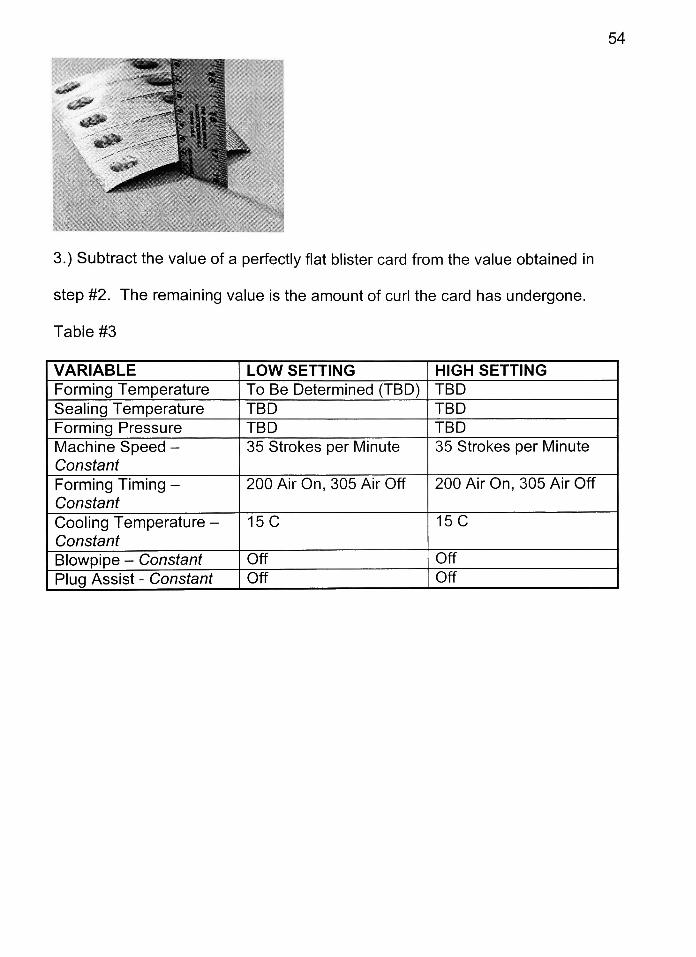
The method used to test the blister cards for card curl is as follows:
1.)Let the blister cards condition for at least 24 hours in a controlled room
temperature and humidity setting (50% RH, 23 degrees C) once they have been
formed. Be sure not to stack the blister cards.
2.) Place the blister cards on a flat surface with the cavities resting on the surface
(lidding material on top). Place a ruler perpendicular to the flat surface and next
to the highest point of the blister card. Read the height of the blister card by
looking across the ruler and recording the value (in mm).
54
__. TCk *^3
"x^
"
' !% la-s-
if'
%4ii0P*
^^(H jff
"
'-^'vft.-^
3.) Subtract the value of a perfectly flat blister card from the value obtained in
step #2. The remaining value is the amount of curl the card has undergone.
Table #3
VARIABLE LOW SETTING HIGH SETTING
Forming Temperature To Be Determined (TBD) TBD
Sealing Temperature TBD TBD
Forming Pressure TBD TBD
Machine Speed -
Constant
35 Strokes per Minute 35 Strokes per Minute
Forming Timing -
Constant
200 Air On, 305 Air Off 200 Air On, 305 Air Off
Cooling Temperature-
Constant
15C 15C
Blowpipe - Constant Off Off
Plug Assist- Constant Off Off
55
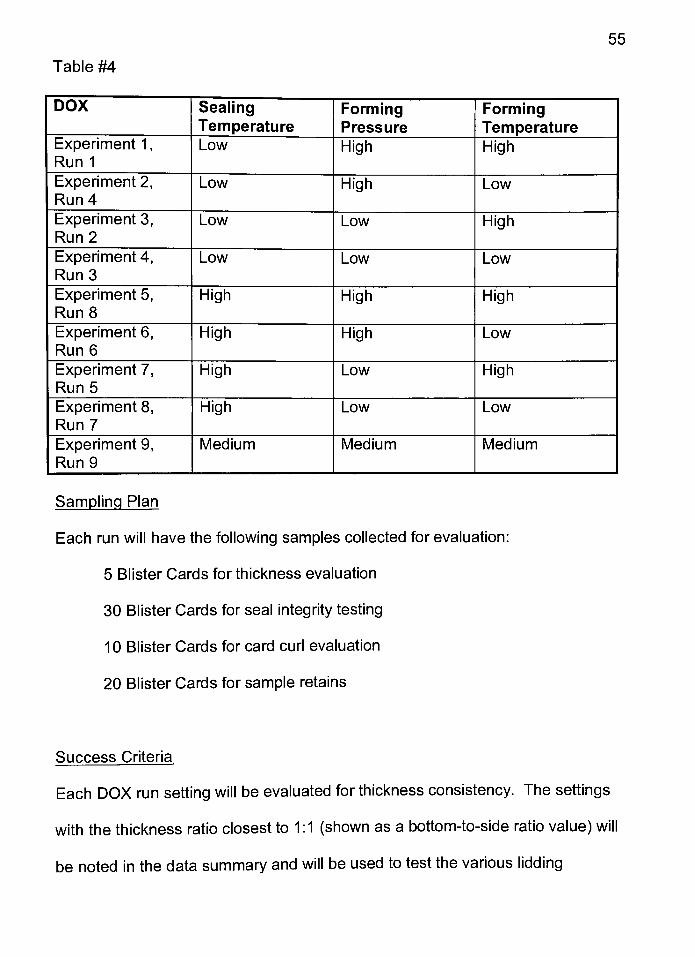
Table #4
DOX SealingTemperature
FormingPressure
FormingTemperature
Experiment 1,
Run 1
Low High High
Experiment 2,Run 4
Low High Low
Experiment 3,
Run 2
Low Low High
Experiment 4,
Run 3
Low Low Low
Experiment 5,
Run 8
High High High
Experiment 6,
Run 6
High High Low
Experiment 7,
Run 5
High Low High
Experiment 8,
Run 7
High Low Low
Experiment 9,
Run 9
Medium Medium Medium
Sampling Plan
Each run will have the following samples collected for evaluation:
5 Blister Cards for thickness evaluation
30 Blister Cards for seal integrity testing
10 Blister Cards for card curl evaluation
20 Blister Cards for sample retains
Success Criteria
Each DOX run setting will be evaluated for thickness consistency. The settings
with the thickness ratio closest to 1:1 (shown as a bottom-to-side ratio value) will
be noted in the data summary and will be used to test the various lidding
56
materials. Since this is only an indicator of moisture permeation, no upper value
will be set for the success criteria.
Each of the blister cards collected will be tested in the vacuum tester for
evidence of a leak. There must be no cavities found to be leakers to be an
acceptable blister manufacturing setting.
The DOX settings and film/foil combinations will be evaluated for card curl
according to the method above. The settings and material combinations with the
lowest card curl will be noted for further testing. No upper limit was established
for card curl but the lower the value the better. Five of the retain samples from
the best DOX settings will be tested to establish WVTR rates. These rates
should be as good or better than the values collected for the PVC film.
Considering all experimental runs and blister card samples, evaluate if any of the
portions of the blister forming/sealing/cutting were not adequate and if any
equipment modifications would improve the blister manufacturing process.
COC DEVELOPMENT SCALE TESTING RESULTS
The first step in the testing according to the test protocol was to determine the
high and low settings for each of the three critical variables mentioned above.
The range found for each of the critical variables is listed below.
57
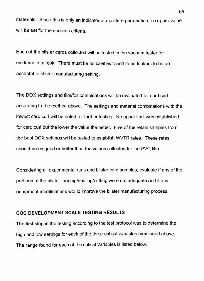
Table #5
Variable
Forming Temperature
Sealing Temperature
Forming Air Pressure
Low Setting129
C168
C
40PSI
High Setting147
C
185C
60PSI
The next step during the testing was to plug the high and low values into the
DOX plan and execute each of the nine runs listed in the protocol. The runs
were randomized and are listed below in the order they were executed.
Table #6
DOX FormingTemperature (C)
SealingTemperature (C)
FormingPressure (PSI)
Run 1 147 168 60
Run 3 129 168 40
Run 4 147 168 40
Run 5 129 185 60
Run 8 147 185 60
Run 2 129 168 60
Run 7 129 185 40
Run 6 147 185 40
Run 9 138 176 50
The results for each of the tests conducted on the blister card samples taken
during the DOX runs listed above are summarized in the tables listed below.
58
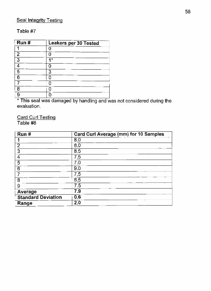
Seal Integrity Testing
Table #7
Run# Leakers per 30 Tested
1 0
2 0
31*
4 0
5 3
6 0
7 0
8 0
9 0
This seal was damaged by handling and was not considered during the
evaluation.
Card Curl Testing
Table #8
Run# Card Curl Average (mm) for 10 Samples
1 8.0
2 8.0
3 8.5
4 7.5
5 7.0
6 9.0
7 7.5
8 8.5
9 7.5
Average 7.9
Standard Deviation 0.6
Range 2.0
59
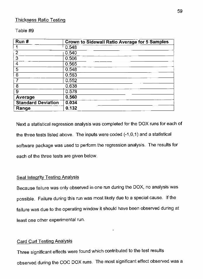
Thickness Ratio Testing
Table #9
Run# Crown to Sidewall Ratio Average for 5 Samples
1 0.548
2 0.540
3 0.506
4 0.565
5 0.548
6 0.563
7 0.552
8 0.638
9 0.578
Average 0.560
Standard Deviation 0.034
Range 0.132
Next a statistical regression analysis was completed for the DOX runs for each of
the three tests listed above. The inputs were coded (-1 ,0,1 ) and a statistical
software package was used to perform the regression analysis. The results for
each of the three tests are given below.
Seal Integrity Testing Analysis
Because failure was only observed in one run during the DOX, no analysis was
possible. Failure during this run was most likely due to a special cause. If the
failure was due to the operating window it should have been observed during at
least one other experimental run.
Card Curl Testing Analysis
Three significant effects were found whichcontributed to the test results
observed during the COC DOX runs. The most significant effect observed was a
60
combination effect of seal temperature and forming temperature (effect value
0.5000). The second significant effect was forming temperature (effect value
0.1875). The last significant effect was forming pressure (effect value -0.1250).
The root mean standard error (RMSE) for these combined effects was 0.30 and
the R-square value was 84.51%.
Thickness Ratio Testing Analysis
Three significant effects were found which contributed to the thickness ratio test
results observed during the COC DOX runs. The most significant effect
observed was forming temperature (effect value 0.02100). The second
significant effect was sealing temperature (effect value 0.01775). The last
significant effect was forming pressure (effect value 0.01 100). The root mean
standard error (RMSE) for these combined effects was 0.02 and the R-square
value was 69.40%.
WVTR Test Results
Based on the DOX analysis above, samples were chosen for WVTR testing.
Samples from DOX run #8 were selected based on no seal integrity failures,
acceptable card curl values, and good thickness ratios. Because this testing
takes a long time to obtain values, itwas not practical to test blister cavities from
each run, instead representative samplesfrom run #8 were selected based on
the tests listed above and one set of testing was performed.
61
Based on the five blister cavities tested, the test results gave a WVTR value of
0.00188 grams of moisture per blister cavity per 24 hours at 100% RH.
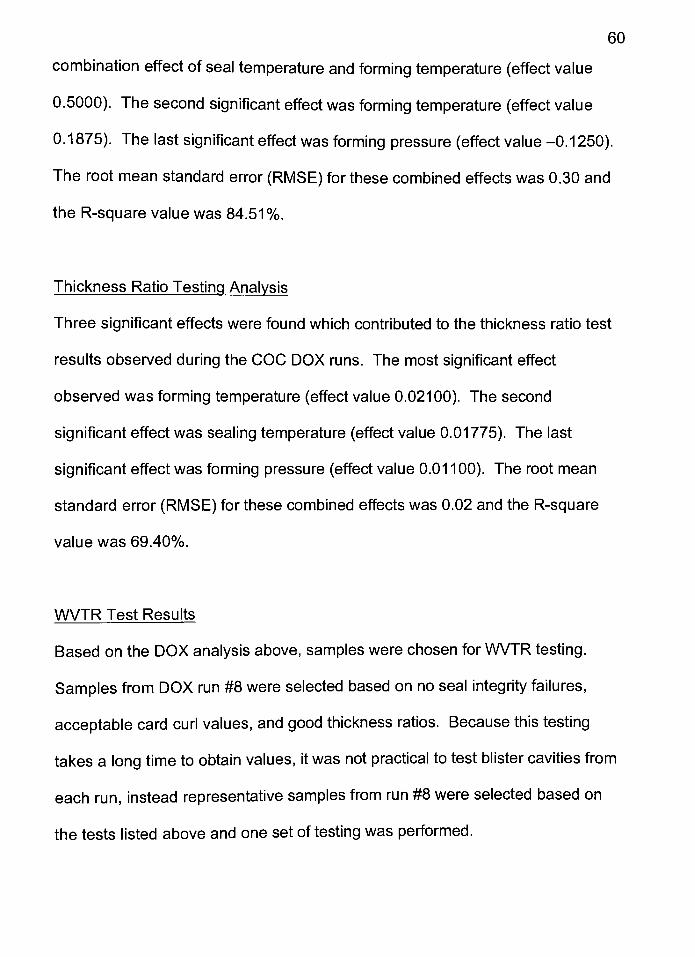
Objective #2 - COC / Lidding Material Compatibility Testing
Three aluminum foil suppliers provided aluminum foil sample rolls for our testing
purposes. All three of the supplier samples were tested to determine the sealing
temperature range required to obtain a good quality seal to the COC blister film.
All other variables were held constant including forming temperature(138
C),
forming pressure (50 PSI), and speed (35 strokes per minute). Results from the
testing can be found in the table below.
Table #10
Supplier Low Temperature High Temperature
Teich160
C190
C
AlgroupWheaton160
C190
C
Hueck168
C185
C
Seal Integrity Testing
10 Blister cards were taken from each of the low and high settings listed above
for each of the three sample types. Results can be found in the table below.
Table #1 1
Supplier Leakers per 10 Cards Tested
Teich1*
AlgroupWheaton 0
Hueck 0
Foil on one cavity dented and should be omitted
62
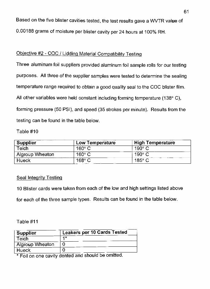
Card Curl Testing
5 Blister cards were taken from each of the low and high settings listed above for
each of the three sample types. Results can be found in the table below.
Table #12
Sample # Teich AlgroupWheaton Hueck
1 (High) 10.0 9.0 8.0
2 (High) 10.0 9.0 8.0
3 (High) 8.5 9.0 7.5
4 (High) 9.0 10.0 8.0
5 (High) 9.0 9.0 7.0
1 (Low) 12.0 10.0 7.0
2 (Low) 12.0 12.0 8.0
3 (Low) 11.0 10.0 7.5
4 (Low) 12.0 11.0 7.5
5 (Low) 10.0 10.0 9.0
Average 10.4 9.9 7.8
Standard Deviation 1.3 0.9 0.6
Range 3.5 3.0 2.0
Objective #3
Lastly, objective #3 was to determine if any modifications or changes to the
blister equipment was necessary to successfully manufacture small scale COC
blister cards. Results of the above mentioned DOX did not suggest that any
changes or modifications to the equipment was necessary.
COC / PVC COMPARISON TESTING
The following section provides data comparing PVC to COC blister film. All data
was collected using the samesmall-scale equipment, tooling, testing equipment,
and testing procedures. Reference previous section for all testing details. The
63
tests, which were executed during this comparison, are considered by some
experts in the industry to be the most critical tests for blister cavity quality.
The testing bracketed small to large size blister cavities. The small tooling cavity
size used was 13.3 x 7.5 x 4.4mm. The large tooling cavity size used was 16.8 x
10.3 x 6.0mm (L x W x D). The blister cards produced by these tools were tested
to determine the optimal operating window, thickness ratios, moisture permeation
rates, card curl, and seal integrity.
Materials used for the COC blister cards were the #8007, 300 micron, Klockner
blister film with an AlgroupWheaton, 30 micron, hard tempered aluminum foil.
The PVC blister cards were made from a PH1 70/01, 250 micron, Klockner blister
film with an AlgroupWheaton, 25 micron, hard tempered aluminum foil. All
blister cards were manufactured on a Klockner EASII small scale blister machine.
Operating Window
A range finding protocol was executed to determine the operating window for
each of the critical variables. The low and high values are listed below for
comparison.
Table #13
Small Cavity PVC COC
Variable Low Value High Value Low Value High Value
Pressure 40 PSI 70 PSI 40 PSI 60 PSI
Seal Temperature160
C180
C157
C 182C
Forming Temperature120
C145
C126
C 155C
64
Table #14
Large Cavity PVC COC
Variable Low Value High Value Low Value High Value
Pressure 60 PSI 90 PSI 40 PSI 60 PSI
Seal Temperature 140C
160C 157C
182C
Forming Temperature120
C145
C126
C155
C
Thickness Ratio
Thickness ratios were calculated on blister cards sampled from each of the DOX
runs using the operating window listed above. The best thickness ratios were
compared for both the PVC and the COC blister cards for the small and large
cavity sizes. Results are listed below and differences were determined to be
small. Thickness ratio data is used as an indicator of the quality of the blister
cavity but the most effective measurement isdetermined by the WVTR testing.
PVC Small Cavity- 1 .3 Crown to Side Ratio
COC Small Cavity - 1 .4 Crown to Side Ratio
PVC Large Cavity - 1 .6 Crown to Side Ratio
COC Large Cavity 1 .6 Crown to Side Ratio
Moisture Vapor Permeation Rate
Moisture vapor permeation rates were collected on blister cards that showed the
best thickness ratios from the above-mentioned testing. The more uniform the
blister cavity thicknessratio is, the lower the MVTR values. The MVTR values
were compared for both the PVC and the COC blister cards for the small and
large cavity sizes. Results are listed below.
65
Table #15
Cavity Size Film Type WVTR Standard Deviation
Small PVC 0.00231 0.00060
Small COC 0.00049 0.00012
Large PVC 0.00312 0.00091
Large COC 0.00064 0.00014
Note: All values are recorded in Grams/Package/Day at 100% RH.
The WVTR testing between PVC and COC showed a 78.8% reduction in WVTR
for the small blister cavity and a 79.5% reduction for the large blister cavity.
Seal Integrity and Card Curl Testing
Seal integrity testing, according to the method mentioned above, showed no
failures that were not attributed to a special cause from either film type during this
testing. Card curl testing was also executed according to the method listed
above and no difference was shown between the PVC and COC blister card
samples.
COMMERCIAL SCALE TEST RUNS
Three data points have been used to evaluate how COC film will compare to
PVC film when run on commercial scale blister manufacturing equipment. Data
has been supplied or collected by the following: 1.)a commercial blister film and
equipment manufacturing company, 2.) qualitative test runs on an Uhlmann UPS
at a contract packaging company,and 3.) a short qualitative test run on a
66
Klockner CP1200 at a pharmaceutical packaging plant. Basic information from
each of these sources is supplied below. Further quantitative testing, which is
outside of the scope of this paper, will be needed to ensure no significant
differences are introduced when moving the manufacturing of COC blister cards
from small to large scale.
One equipment and film manufacturer provided data on COC and PVC reliability
data from their experience. Both PVC and COC films have been run on their
equipment during several trade-shows over the past few years. Their experience
has shown that PVC and COC films are interchangeable. They have
experienced no differences in scrap rates, reliability, or quality. The biggest
differences they have noted were that COC films can be run using slightly cooler
forming and sealing temperatures and that they were able to run the COC films
at faster line speeds. During the trade shows mentioned above this supplier was
able to switch from PVC to COC film and back without any significant
adjustments or modifications to the commercial scale equipment.
A short development run was executed at a pharmaceutical plant in Europe.
This trial was used to show that COC could be used as a substitute for PVC on
high-speed commercial equipment. While this experimental trial was only
evaluated using qualitative measures, no significant issues were observed with
forming, sealing, or punching.
67
Lastly, a short set of experimental runs was executed at a United States based
contract packaging firm. The purpose of these runs was to determine if COC
would work for a specific product application and to collect preliminary
information on the commercial operating window. One fact learned from this run
was that COC does need to be run on coated tooling. At first the COC material
was formed in non-coated PVC tooling and did have some problems with sticking
in the forming cavities. Once the tools were changed and coated tools were
tested, no further issues were experienced. The operating window was found to
be as wide as typically seen with PVC and the forming, sealing, and punching
stations all worked the same as with the more common PVC materials.
CONCLUSION
Based on the information and data provided in the above sections, the null
hypothesis has been proven false. It has been demonstrated that cyclic olefin
copolymer is a potential alternative to polyvinyl chlorine for use in blister
packaging.
The chemical structure of COC and environmental assessments completed
indicate that COC is relatively inert, easily breaks down into carbon dioxide and
water when properly incinerated, and it is not expected to have any long-term
adverse environmental impacts. It has been shown to have physical and
chemical characteristics that make it compatible with thermoforming processes.
The COC film has been shown to run well on small-scale blister packaging
equipment and qualitative data has been provided on commercial equipment.
When compared to PVC materials, the blister cards made from COC exhibited
equivalent card curl, clarity, thickness ratios, seal integrity, width of operating
window, and significantly lower moisture permeation rates.
Since the material is relatively new to the technical community, the current
drawback is the material cost. As material sales rise and new innovations allow
a decrease in production costs, the material price should fall allowing greater
interest for a broad range of applications including pharmaceutical blister
packaging.
68
REFERENCES
1 Hammer, S., & Newsham, M. (1998, April). Section 1: An Introduction to
PVC. In The Case Against PVC Packaging [On-line]. Available:
www.pirg.org/masspirg/enviro/sw/pvc/ p. 1-2.
2 Hammer, S., & Newsham, M. (1998, April). Section 1: An Introduction to
PVC. In The Case Against PVC Packaging [On-line]. Available:
www.pirg.org/masspirg/enviro/sw/pvc/ p. 3.
3 Commission of the European Communities. (2000, July). Section 3: The use
of Additives in PVC. In Green Paper: Environmental Issues of PVC. p. 13.
4 Commission of the European Communities. (2000, July). Section 3: The use
of Additives in PVC. In Green Paper: Environmental Issues of PVC. p. 8.
5 Hammer, S., & Newsham, M. (1998, April). Section 2: The Problems with
PVC. In The Case Against PVC Packaging [On-line]. Available:
www.pirg.org/masspirg/enviro/sw/pvc/ p. 1.
6 Commission of the European Communities. (2000, July). Section 3: The use
ofAdditives in PVC. In Green Paper: Environmental Issues of PVC. p. 12.
7 The Vinyl Institute. (1994, August). In The Truth About Vinyl: An Analysis
and Response to the Greenpeace Document No Future for PVC. p. 14-15.
8 Chlorophiles (non-profit organization). (2000, June). Section: Chlorine Input
and Dioxin Emissions. In Chlorophiles [On-line]. Available:
www.ping.be/~ping5859/Eng/Chlolrphiles.html p. 5.
9 Commission of the European Communities. (2000, July). Section 3: The use
69
70
ofAdditives in PVC. In Green Paper: Environmental Issues of PVC. p. 12.
10 The Vinyl Institute. (1992, December). In Some Common Misperceptions
About Vinyl, p. 4.
11 The Vinyl Institute. (1994, August). In The Truth About Vinyl: An Analysis
and Response to the Greenpeace Document No Future for PVC. p. 16, 18.
12 Greenpeace International. (1993). In No Future for PVC. p. 4.
13 The Vinyl Institute. (1994, August). In The Truth About Vinyl: An Analysis
and Response to the Greenpeace Document No Future for PVC. p. 17.
14 The Vinyl Institute. (1994, August). In The Truth About Vinyl: An Analysis
and Response to the Greenpeace Document No Future for PVC. p. 16, 18.
15 The Vinyl Institute. (1994, August). In The Truth About Vinyl: An Analysis
and Response to the Greenpeace Document No Future for PVC. p. 11.
16 The Vinyl Institute. (1994, August). In The Truth About Vinyl: An Analysis
and Response to the Greenpeace Document No Future for PVC. p. 17.
17 Greenpeace International. (1993). In No Future for PVC. p. 5.
18 Hammer, S., & Newsham, M. (1998, April). Section 2: The Problems with
PVC. In The Case Against PVC Packaging [On-line]. Available:
www.pirg.org/masspirg/enviro/sw/pvc/ p. 3.
19 Greenpeace International. (1993). In PVC Waste and Recycling. [On-line].
Available: www.greenpeace.org p. 2-3.
20 Commission of the European Communities. (2000, July). Section 3: The use
of Additives in PVC. In Green Paper: Environmental Issues of PVC. p. 24.
71
21 The Vinyl Institute. (1994, August). In The Truth About Vinyl: An Analysis
and Response to the Greenpeace Document No Future for PVC. p. 17.
22 Greenpeace International. (1993). In PVC Waste and Recycling. [On-line].
Available: www.greenpeace.org p. 4.
23 Greenpeace International. (1993). In PVC Waste and Recycling. [On-line].
Available: www.greenpeace.org p. 5.
24 The Vinyl Institute. (1994, August). In The Truth About Vinyl: An Analysis
and Response to the Greenpeace Document No Future for PVC. p. 16.
25 Hammer, S., & Newsham, M. (1998, April). Section 3: PVC and Dioxin. In
The Case Against PVC Packaging [On-line]. Available:
www.pirg.org/masspirg/enviro/sw/pvc/ p. 1-2.
26 Greenpeace International. (1993). In No Future for PVC. p. 1.
27 Greenpeace International. (1993). In PVC Waste and Recycling. [On-line].
Available: www.greenpeace.org p. 3-4.
28 Commission of the European Communities. (2000, July). Section 3: The use
ofAdditives in PVC. In Green Paper: Environmental Issues of PVC. p. 25.
29 The Vinyl Institute. (1994, August). In The Truth About Vinyl: An Analysis
and Response to the Greenpeace Document No Future for PVC. p. 10.
30 Chlorophiles (non-profit organization). (2000, June). Section: Chlorine Input
and Dioxin Emissions. In Chlorophiles [On-line]. Available:
www.ping.be/~ping5859/Eng/Chlolrphiles.html p. 4.
72
31 Chlorophiles (non-profit organization). (2000, June). Section: Chlorine In the
World. In Chlorophiles [On-line]. Available:
www.ping.be/~ping5859/Eng/Chlolrphiles.html p. 2.
32 Chlorophiles (non-profit organization). (2000, June). Section: Chlorine In the
World. In Chlorophiles [On-line]. Available:
www.ping.be/~ping5859/Eng/Chlolrphiles.html p. 1.
33 Chlorophiles (non-profit organization). (2000, June). Section: Chlorine Input
and Dioxin Emissions. In Chlorophiles [On-line]. Available:
www.ping.be/~ping5859/Eng/Chlolrphiles.html p. 4.
34 Hammer, S., & Newsham, M. (1998, April). Section 3: PVC and Dioxin. In
The Case Against PVC Packaging [On-line]. Available:
www.pirg.org/masspirg/enviro/sw/pvc/ p. 4.
35 Chlorophiles (non-profit organization). (2000, June). Section: Sources of
Dioxin. In Chlorophiles [On-line]. Available:
www.ping.be/~ping5859/Eng/Chlolrphiles.html p. 7.
36 Chlorophiles (non-profit organization). (2000, June). Section: Chlorine, PVC
and Dioxins. In Chlorophiles [On-line]. Available:
www.ping.be/~ping5859/Eng/Chlolrphiles.html p. 1.
37 Ticona Communications Department (1998, July). In Ticona Builds 30,000
Ton Capacity Topas (COC) Plant in Oberhausen. p. 2
38 Beer, E. (1997). In Hoechst: The new Group Structure- A Strategic
Management Holding [Technical Presentation]. Ticona GmbH, Frankfurt,
Germany.
73
39 Ticona Communications Department (1998, July). In Ticona Builds 30,000
Ton Capacity Topas (COC) Plant in Oberhausen. p. 1
40 Beer, E. (1997). In Hoechst: The new Group Structure - A Strategic
Management Holding [Technical Presentation]. Ticona GmbH, Germany.
41 Dr. Hatke, W. (1997). In Cvcloolefin-Copolymers for Packaging Applications
[Technical Presentation]. Ticona GmbH, Frankfurt, Germany.
42 Weller, T., Detlef, S., & McNally, D., (1997, June). New Engineering
Polyolefin Offers Clear Processing Opportunities. Plastics Technology,
volume 43, #6, p.58-60.
43 Beer, E., (1997). In Thermoplastic Olefinic Polymers ofAmorphous
Structure [Technical Presentation]. Ticona GmbH, Frankfurt, Germany.
44 Dr. Hatke, W. (1997). In Cvcloolefin-Copolymers for Packaging Applications
[Technical Presentation]. Ticona GmbH, Frankfurt, Germany.
45 Beer, E., Goerlitz, W., & Heukelbach, (2000). In Customized Conversion -
Topas packaging film with specific properties, p. 9.
46 Ticona Communications Department (2000, August). In Topas
Thermoplastic Olefin ofAmorphous Structure (COC). p. 13
47 Lamonte, R., & McNally, D., (2000, June). Uses and Processing of Cyclic
Olefin Copolymers (COC). Plastics Engineering, Volume 56, Number 6, p.
51.
48 Ticona Communications Department (1998, July). In Ticona Builds 30,000
Ton Capacity Topas (COC) Plant in Oberhausen. p. 1
74
49 Beer, E., (1999, January). In Topas COC for Pharmaceutical Push
Through Packs. Presentation given at Blister Pack 2000 conference in Koln
Germany.
50 E. Beer (personal communication [E-mail], January 10, 2001).
51 Hanlon, J. F., (1992). Handbook of Packaging Engineering(2nd
ed.).
Lancaster, PA: Technomic Publishing AG. pp. 8.71-8.73.
52 Jenkins, W. A. & Osborn, K. R., (1993). Packaging Drugs and
Pharmaceuticals. Lancaster, PA: Technomic Publishing AG. pp. 150-152.

ATTACHMENT #1
Product Name:
Product Code:
MSDS Number:
Revision Number:
Version Date:
Material Safety Data SheetTopas
5013, 5513, 6013, 6015, 6017, 8007
TP1000
1
1/1/98
nconaPage 1 of 5
Print Date 2/26/98 1:37:15 PM
Section I. Chemical, Product and Company Identification
Product Name:
Product Code:
MSDS Number:
Synonyms:
Manufacturer:
Product Use:
TP1000
CYCLIC OLEFIN COPOLYMER
CYCLIC POLYOLEFIN
TICONA (formerly Hoechst Celanese Corporation)90 MORRIS AVE.
SUMMIT, NJ. 07901
UNITED STATES
Engineering thermoplastic.
MSDS Prepared By: O. Schnellenberger
Section 2. Composition/Information on Ingredients
Ingredients: Ingredient
Base Resin
CAS Number
26007-43-2
This is a polymeric material. All constituents are wetted by the polymer system, and
therefore, present no likelihood of exposure under normal conditions of processing and
handling.
This product contains proprietary ingredients.
While this product is not classified as hazardous under OSHA Regulations, this MSDS
contains valuable information critical to the safe handling and proper use of the product.This MSDS should be retained and made available for employees and other users of the
product.
This product is not regulated by WHMIS.
Section 3. Hazards Identification
Emergency Overview:
Potential Health Effects:
Routes ofExposure:
Signs and Symptoms of
Exposure:
Immediate Effects:
Skin:
Pellets or chips with slight to no odor. Combustion and decomposition may produce
hazardous fumes. Base resin dust/powder has a US Bureau ofMines relative dust
explosion hazard rating ofweak. Molten material can cause thermal burns on contact with
skin or eyes. Spilled pellets may create a slipping hazard.
Skin and eye contact. Inhalation of vapors, if overheated.
No specific information available.
No specific information available on the product. Hot or molten material has the potential
Transportation Emergency:
Product Emergency:
Product Information:
(800)424-9300 CHEMTREC - 24 hrs in USA
(703)527-3887 Outside USA
(888)522-7816 Ticona - 24 hrs/day
(800)833-4882
The Hoechst name and logo are registered trademarks ol Hoechst AG.
HoechstTicona - A member of the
Hoechst Group
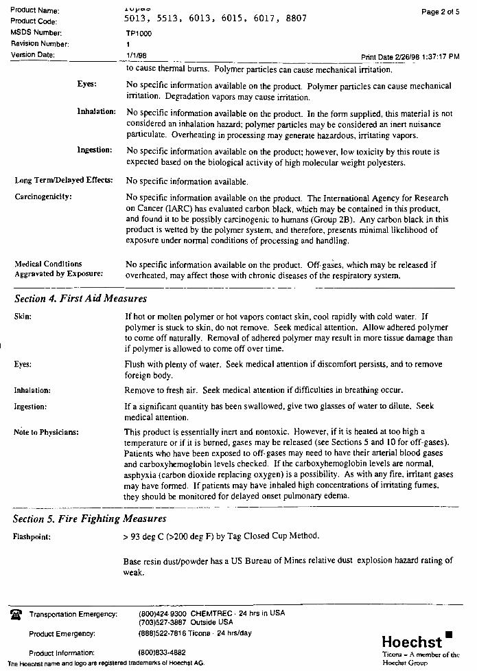
Product Name:
Product Code:
MSDS Number:
Revision Number:
Version Date:
5013, 5513, 6013, 6015, 6017, 8807
TP1000
1
1/1/98
Page 2 of 5
Print Date 2/26/98 1:37:17 PM
Eyes:
Inhalation:
Ingestion:
Long Term/Delayed Effects:
Carcinogenicity:
to cause thermal burns. Polymer particles can cause mechanical irritation.
No specific information available on the product. Polymer particles can cause mechanical
irritation. Degradation vapors may cause irritation.
No specific information available on the product. In the form supplied, this material is not
considered an inhalation hazard; polymer particles may be considered an inert nuisance
particulate. Overheating in processing may generate hazardous, irritating vapors.
No specific information available on the product; however, low toxicity by this route is
expected based on the biological activity of high molecular weight polyesters.
No specific information available.
No specific information available on the product. The International Agency for Research
on Cancer (1ARC) has evaluated carbon black, which may be contained in this product,
and found it to be possibly carcinogenic to humans (Group 2B). Any carbon black in this
product is wetted by the polymer system, and therefore, presents minimal likelihood of
exposure under normal conditions of processing and handling.
Medical Conditions
Aggravated by Exposure:No specific information available on the product. Off-gases, which may be released if
overheated, may affect those with chronic diseases of the respiratory system.
Section 4. First AidMeasures
Skin:
Eyes:
Inhalation:
Ingestion:
Note to Phvsicians:
If hot or molten polymer or hot vapors contact skin, cool rapidly with cold water. If
polymer is stuck to skin, do not remove. Seek medical attention. Allow adhered polymer
to come off naturally. Removal of adhered polymer may result in more tissue damage than
if polymer is allowed to come off over time.
Flush with plenty of water. Seek medical attention if discomfort persists, and to remove
foreign body.
Remove to fresh air. Seek medical attention if difficulties in breathing occur.
If a significant quantity has been swallowed, give two glasses of water to dilute. Seek
medical attention.
This product is essentially inert and nontoxic. However, if it is heated at too high a
temperature or if it is burned, gases may be released (see Sections 5 and 10 for off-gases).
Patients who have been exposed to off-gases may need to have their arterial blood gases
and carboxyhemoglobin levels checked. If the carboxyhemoglobin levels are normal,
asphyxia (carbon dioxide replacing oxygen) is a possibility. As with any fire, irritant gases
may have formed. If patients may have inhaled high concentrationsof irritating fumes,
they should be monitored for delayed onset pulmonary edema.
Section 5. Fire FightingMeasures
Flashpoint: > 93 deg C (>200 deg F) by Tag Closed Cup Method.
Base resin dust/powder has a US Bureau ofMines relative dust explosion hazard rating of
weak.
Transportation Emergency:
Product Emergency:
(800)424-9300 CHEMTREC - 24 hrs in USA
(703)527-3887 Outside USA
(888)522-7816 Ticona - 24 hrs/day
Product Information: (800)833-4882
The Hoechst name and logo are registered trademarks ol Hoechst AG.
HoechstTicona - A member of the
Hoechst Group
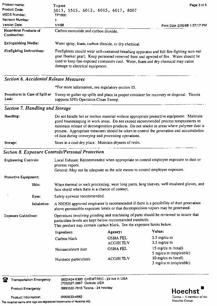
Proauct Name:
Product Code:
MSDS Number:
Revision Number:
Version Date:
Hazardous Products of
Combustion:
Extinguishing Media:
Firefighting Instructions:
Topas
5013, 5513,
TP1000
1
1/1/98
6013, 6015, 6017, 8007
Carbon monoxide and carbon dioxide.
Water spray, foam, carbon dioxide, or dry chemical.
Page 3 of 5
Print Date 2/26/98 1:37:17 PM
Firefighters should wear self-contained breathing apparatus and full fire-fighting turn-out
gear (bunker gear). Keep personnel removed from and upwind of fire. Water should be
used to keep fire-exposed containers cool. Water, foam and dry chemical may cause
damage to electrical equipment.
Section 6. AccidentalRelease Measures
*For more information, see regulatory section 15.
Procedures in Case of Spill or Sweep or gather up spills and place in proper container for recovery or disposal. TiconaLeak: sunnnrtc .9PI'<; Onpratinn Plpan Su/ppnsupports SPI's Operation Clean Sweep.
Section 7. Handling and Storage
Handling:
Storage:
Do not handle hot or molten material without appropriate protective equipment. Maintain
good housekeeping in work areas. Do not exceed recommended process temperatures to
minimize release of decomposition products. Do not smoke in areas where polymer dust is
present. Appropriate measures should be taken to control the generation and accumulation
of dust during conveying and processing operations.
Store in a cool dry place. Maintain dryness of resin.
Section 8. Exposure Controls/Personal Protection
Engineering Controls:
Protective Equipment:
Skin:
Eyes:
Inhalation:
Exposure Guidelines:
Local Exhaust: Recommended when appropriate to control employee exposure to dust or
process vapors.
General: May not be adequate as the sole means to control employee exposure.
When thermal or melt processing, wear long pants, long sleeves, well insulated gloves, and
face shield when there is a chance of contact.
Safety eyewear recommended.
A NIOSH approved respirator is recommended if there is a possibility of dust generation
above permissible exposure limits or that decomposition vapors may be generated.
Operations involving grinding and machining of parts should be reviewed to assure that
particulate levels are kept below recommended standards.
This product may contain carbon black.See the exposure limits below.
Ingredient:
Carbon black
Nuisance/inert dust
Nuisance particulates
Agency:
OSHA PEL
ACGIH TLV
OSHA PEL
ACGIH TLV
Value:
3.5 mg/cu m
3.5 mg/cu m
15 mg/cu m (total)
5 mg/cu m (respirable)
10 mg/cu m (total)
3 mg/cu m (respirable)
Transportation Emergency:
Product Emergency:
(800)424-9300 CHEMTREC - 24 hrs in USA
(703)527-3887 Outside USA
(888)522-7816 Ticona - 24 hrs/day
Product Information: (800)833-4882
The Hoechst name and logo are registered trademarks ol Hoechst AG.
HoechstTicona - A member of the
Hoechst Group

Product Name:
Product Code:
MSDS Number:
Revision Number:
Version Date:
Topas
5013, 5513, 6013, 6015, 6017, 8007
TP1000
1
1/1/98
Page 4 of 5
Print Date 2/26/98 1:37:18 PM
Section 9. Physical and Chemical Properties
Appearance: Pellets
Odor: Slight characteristic odor
Physical State: Solid
Vapor Pressure: < 0.001 mm Hg
Melting Point:
Softening Point:
Solubility:
Specific Gravity:
Percent Volatiles:
MolecularWeight:
Softens over a wide temperature range
100 - 200 deg C (212 - 392 deg F)
negligible < 0.1% (in water)
1.0-1.1
< 0.5 by weight
Approximately 5000 Daltons
Section 10. Stability andReactivity
Stable under ordinary conditions of use and storage.
Fire; do not heat above 752 deg F (400 deg C).
Strong oxidizing agents.
Carbon monoxide, carbon dioxide, and hydrocarbons.
Chemical Stability:
Conditions to Avoid
Incompatibility:
Hazardous Decomposition
Products:
Hazardous Polvmerization: Will not occur.
Section 11. Toxicological Information
No specific information available on the product.
Inhalation of carbon black, a possible ingredient, has been shown to cause lung tumors in
rats at high exposure concentrations. These concentrations appear to exceed the capacity
of the lung to clear the carbon black particles, thus resulting in significant toxicity.
Section 12 Ecological Information
Ecotoxicity: The effects of resin pellets on the wildlife that may ingest them is not well understood. In
the case of seabirds, some marine biologists believe that the fowl may not be able to pass
plastic pellets through their digestive tracts. Thus, large quantities of ingested pellets may
cause intestinal blockage, false feelings of satiation or reduction in absorption of nutrients,
causing malnutrition and starvation. The goal of SPI's Operation Clean Sweep is zero loss
of pellets into the environment.
Environmental
Fate/Information:
This material is considered to be non-biodegradable.
Section 13. Disposal Considerations
Transportation Emergency:
Product Emergency:
(800)424-9300 CHEMTREC - 24 hrs in USA
(703)527-3887 Outside USA
(888)522-7816 Ticona - 24 hrs/day
Product Information: (800)833-4882
The Hoechst name and logo are registered trademarks of Hoechst AG.
HoechstTicona A member of the
Hoechst Group
Product Name:
Product Code:
MSDS Number:
Revision Number:
Version Date:
Topas
5013, 5513, 6013, 6015, 6017, 8007
TP1000
1
1/1/98
Disposal:
Page 5 of 5
Print Date 2/26/98 1:37:18 PM
Recycling is encouraged. Incinerate or landfill in accordance with federal, state, and local
regulations. This product, as shipped, is not a RCRA hazardous waste under present EPA
regulations.
Section 14. Transport Information
Not regulated under US Department ofTransportation.
Section 15. Regulatory Information
TSCA: AI1 the components of this product comply with TSCA Regulations.
This product does not contain any toxic chemicals subject to the reporting requirements of
Section 313 of the Emergency Planning and Community Right-to-Know Act of 1986 and
of40CFR372.
Section 16. Other Information
Hazard Ratings:
Disclaimer:
Agency
NFPA
HMIS
Health Flammability Reactivity
1 1 0
0 1 0
Note 1 : NFPA and HMIS ratings are as determined by Ticona.
Other
Note 2: Revisions in this MSDS Version include adding hazards of carbon black. Section
2,3,8,10.
This product is not intended for use in medical or dental implants.
Refer to the appropriate Ticona bulletins for specific processing guidance and good
manufacturing practices (purging, processing parameters, shutdown, etc.).
The information contained herein is accurate to the best of our knowledge. We do not
suggest or guarantee that any hazards listed herein are the only ones which exist. Ticona
makes no warranty of any kind, express or implied, concerning the safe use of this material
in your process or in combination with other substances. Effects can be aggravated byother materials and/or this material may aggravate or add to the effects of other materials.
User has the sole responsibility to determine the suitability of the materials for any use and
the manner of use contemplated. User must meet all applicable safety and health standards.
Transportation Emergency:
Product Emergency:
(800)424-9300 CHEMTREC - 24 hrs in USA
(703)527-3887 Outside USA
(888)522-7816 Ticona - 24 hrs/day
Product Information: (800)833-4882
The Hoechst name and logo are registered trademarks of Hoechst AG.
HoechstTicona - A member of the
Hoechst Group
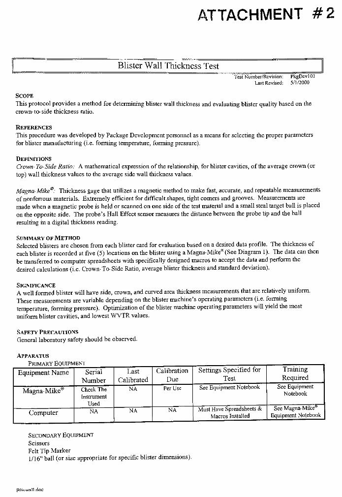
ATTACHMENT #2
BlisterWall Thickness Test
Test Number/Revision: PkgDevlOl
Last Revised: 5/1/2000
Scope
This protocol provides a method for determining blister wall thickness and evaluating blister quality based on the
crown-to-side thickness ratio.
References
This procedure was developed by Package Development personnel as a means for selecting the proper parameters
for blister manufacturing (i.e. forming temperature, forming pressure).
Definitions
Crown-To-Side Ratio: A mathematical expression of the relationship, for blister cavities, of the average crown (or
top) wall thickness values to the average side wall thickness values.
Magna-Mike
: Thickness gage that utilizes a magnetic method to make fast, accurate, and repeatable measurements
of nonferrous materials. Extremely efficient for difficult shapes, tight corners and grooves. Measurements are
made when a magnetic probe is held or scanned on one side of the test material and a small steal target ball is placed
on the opposite side. The probe's Hall Effect sensor measures the distance between the probe tip and the ball
resulting in a digital thickness reading.
Summary ofMethod
Selected blisters are chosen from each blister card for evaluation based on a desired data profde. The thickness of
each blister is recorded at five (5) locations on the blister using aMagna-Mike
(See Diagram 1). The data can then
be transferred to computer spreadsheets with specifically designed macros to accept thedata and perform the
desired calculations (i.e. Crown-To-Side Ratio, average blister thickness and standard deviation).
Significance
A well formed blister will have side, crown, and curved area thicknessmeasurements that are relatively uniform.
These measurements are variable depending on the blistermachine's operating parameters(i.e. forming
temperature, forming pressure). Optimization of the blistermachine operating parameters will yield the most
uniform blister cavities, and lowestWVTR values.
Safety Precautions
General laboratory safety should be observed.
Apparatus
Primary Equipment
Equipment Name Serial
Number
Last
Calibrated
Calibration
Due
Settings Specified for
Test
Training !
Required
Magna-Mike Check The
Instrument
Used
NA Per Use See Equipment Notebook See Equipment
Notebook
Computer NA NA NA Must Have Spreadsheets &
Macros Installed
SeeMagna-Mike
Equipment Notebook
Secondary Equipment
Scissors
Felt TipMarker
1/16"
ball (or size appropriate for specific blister dimensions).
plicu/all.doc
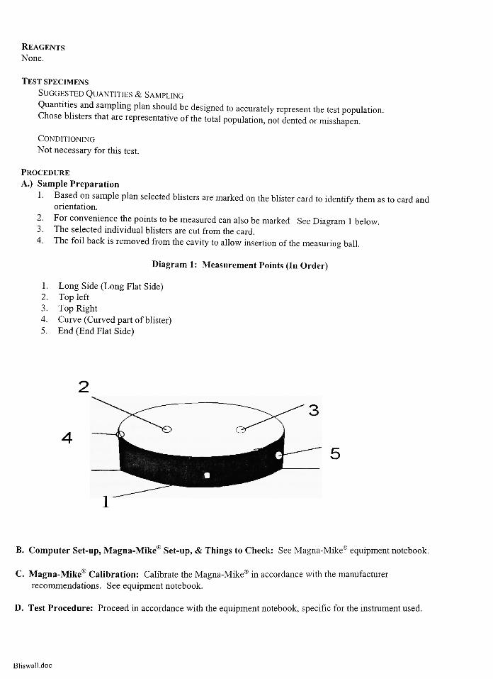
Reagents
None.
Test specimens
SuggestedQuantities & Sampling
Quantities and sampling plan should be designed to accurately represent the test population.Chose blisters that are representative of the total population, not dented or misshapen.
Conditioning
Not necessary for this test.
Procedure
A.) Sample Preparation
1 . Based on sample plan selected blisters are marked on the blister card to identify them as to card and
orientation.
2. For convenience the points to be measured can also be marked See Diagram 1 below.3. The selected individual blisters are cut from the card.
4. The foil back is removed from the cavity to allow insertion of the measuring ball.
Diagram 1 : Measurement Points (In Order)
1 . Long Side (Long Flat Side)2. Top left
3. Top Right
4. Curve (Curved part ofblister)5. End (End Flat Side)
B. Computer Set-up,Magna-Mike
Set-up, & Things to Check: SeeMagna-Mike
equipment notebook.
C.Magna-Mike
Calibration: Calibrate theMagna-Mike
in accordance with the manufacturer
recommendations. See equipment notebook.
D. Test Procedure: Proceed in accordance with the equipment notebook, specific for the instrument used.
Bliswall.doc
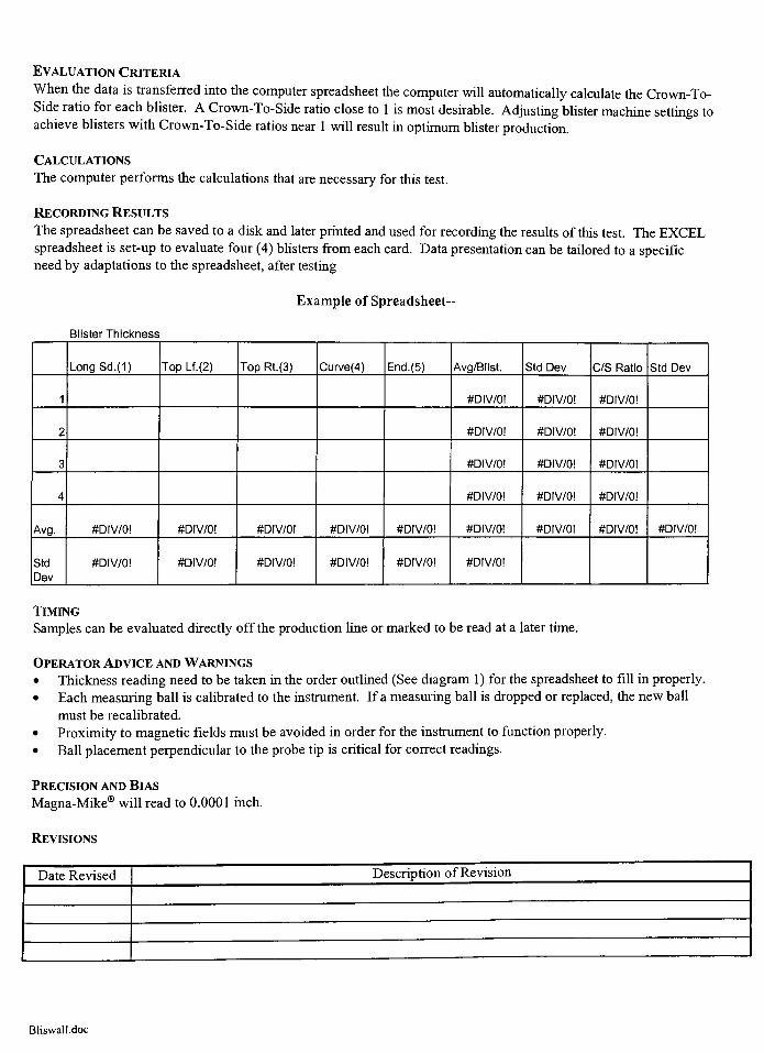
EvaluationCriteria
When the data is transferred into the computer spreadsheet the computer will automatically calculate the Crown-To-
Side ratio for each blister. A Crown-To-Side ratio close to 1 is most desirable. Adjusting blistermachine settings toachieve blisters with Crown-To-Side ratios near 1 will result in optimum blister production.
Calculations
The computer performs the calculations that are necessary for this test.
RecordingResults
The spreadsheet can be saved to a disk and later printed and used for recording the results of this test. The EXCEL
spreadsheet is set-up to evaluate four (4) blisters from each card. Data presentation can be tailored to a specific
need by adaptations to the spreadsheet, after testing.
Example of Spreadsheet-
Blister Thickness
LongSd.(1) Top Lf.(2) Top Rt.(3) Curve(4) End. (5) Avg/Blist. Std Dev C/S Ratio Std Dev
1 #DIV/0! #DIV/0! #DIV/0!
2 #DIV/0! #DIV/0! #DIV/0!
3 #DIV/0! #DIV/0! #DIV/0!
4 #DIV/0! #DIV/0! #DIV/0!
Avg. #DIV/0! #DIV/0! #DIV/0! #DIV/0! #DIV/0! #DIV/0! #Dlv70! #DIV/0! #DIV/0!
Std
Dev
#DIV/0! #DIV/0! #DIV/0! #DIV/0! #DIV/0! #DIV/0!
Timing
Samples can be evaluated directly off the production line or marked to be read at a later time.
OperatorAdvice andWarnings
Thickness reading need to be taken in the order outlined (See diagram 1 ) for the spreadsheet to fill in properly.
Each measuring ball is calibrated to the instrument. If a measuring ball is dropped or replaced, the newball
must be recalibrated.
Proximity to magnetic fields must be avoided in order for the instrument to function properly.
Ball placement perpendicular to the probe tip is critical for correct readings.
Precision andBias
Magna-Mikewill read to 0.0001 inch.
Revisions
Date Revised Description ofRevision
Bliswall.doc
ATTACHMENT #3
Water Vapor Transmission Rate (WVTR)-Blisters
Test Number/Revision: PkgDevl21
Last Revised: 11/19/96
Scope
This protocol provides a method for determining the water vapor transmission rate through a formed
blister.
References
Mocon Permatran W600 Equipment Notebooks (4)Technical Bulletin 098-A
Definitions
None.
Summary ofMethod
Blisters are placed in the Mocon Permatran as a permeable barrier between a 100% relative humidity
environment and a stream of nitrogen. The nitrogen carriers water vapor that has permeated through the
blister to a sensitive infrared sensor. The output of this sensor is proportional to transmission rate.
Significance
Blisters must be tested forwater vapor transmissions to meet FDA regulations. Water vapor transmission
rates are often compared to establish the equivalency of packages or to determinethe effects of changes
of material and forming technique on the package.
Safety Precautions
Safety glasses are required for operation of the Mocon Permatran
General laboratory safety should be observed.
Apparatus
Primary Equipment
Equipment Name Serial
Number
Last
Calibrated
Calibration
Due
Settings Specified for
Test
Training
Required
Mocon Permatran
W600/Rack 10
0790042Suggested:
Nflow= 30 Tflow= 15
See equip, notebook
Environmental Room NA NA NA 73.4+/-3.4F, 50% RH No
Secondary Equipment
Mocon Permatran Sample Cells
Mocon Permatran Rubber Gaskets
Known barrier material (ex. 5 mil Mylar)
Foil Masks
Fiber Pads
Distilled Water
Halocarbon Grease 25-52 or equivalent silicon grease
Shears
Punch Set
Preparations
Adjust temperature, test flow, and nitrogen flow to test settings.
Preform SCAL using a known barrier.
Insure that the P-W600 Interface is reading positive voltages.
Reagents
None.
Test specimens
Suggested Quantities
5 blisters
Sampling
Choose samples randomly.
Conditioning
Condition blisters contained in sample cells in the Mocon Permatran W600 Rack 10 at 100% relative
humidity and test temperatures for 3 days.
Procedure
Follow procedures suggested in the Mocon Permatran Equipment Manual 3 of 4 and Technical Bulletin
098-A
Evaluation Criteria
All blisters of the same material and forming process should have similar water vapor transmission rates.
Calculations
None.
Recording Results
A data sheet including calculations is available for recording the results of this test.
Timing
Estimated Planning Time
Allow time to receive materials and form blisters.
Allow ample time for careful sample preparation.
24 hours sample conditioning in Rack 10
1 hour to verify that the P-W600 Interface is reading positive values.
Estimated Run Time
SCAL and sample run times can be as long as (3) or (4) days
OperatorAdvice andWarnings
Prepare samples carefully. Sample preparation is critical to the test.
Use caution when punching masks to fit blisters. SHARP!
Do not get silicon grease on the samples.
Use only a small amount of grease. Do not get grease in the equipment tubing.
Watch the nitrogen indicating light. When it turns red, notify the equipmentowner.
Precision and Bias
Not yet determined.
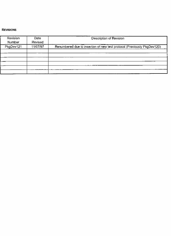
Revisions
Revision
Number
Date
Revised
Description of Revision
PkgDev121 11/07/97 Renumbered due to insertion of new test protocol (Previously PkgDev120)