Embed Size (px)
Citation preview
www.elsevier.nl/locate/jelechem
Journal of Electroanalytical Chemistry 481 (2000) 1–6
Cyclic and convolution potential sweep voltammetry of reversibleion transfer across a liquid membrane
Zdenek Samec a,*, Antonın Trojanek a, Jan Langmaier a, Eva Samcova b
a The J. Heyro6sky Institute of Physical Chemistry, Academy of Sciences of the Czech Republic, Dolejsko6a 3, 182 23 Prague 8, Czech Republicb 3rd Medical Faculty, Charles Uni6ersity Ruska 87, 100 00 Prague 10, Czech Republic
Received 11 August 1999; received in revised form 29 October 1999; accepted 9 November 1999
Abstract
The theory of the cyclic and convolution potential sweep voltammetry of the reversible ion transfer across a liquid membraneis developed. The model system consists of the planar layer of an organic solvent separating two aqueous phases, each containinga supporting electrolyte. The transferred ion is supplied from one of the aqueous phases. It is shown that the coupling betweenthe ion transfer processes at the two membrane interfaces has an effect on the shape and position of the voltammogram on thepotential scale. The theory is used to evaluate the diffusion coefficient and the standard ion transfer potential of a semi-hydropho-bic ion, i.e. protonated tetracaine, from voltammetric measurements in a supported o-nitrophenyl octyl ether (o-NPOE)membrane cell. These results agree well with the data inferred from measurements of the ion transfer across a singlewater � o-NPOE interface. © 2000 Elsevier Science S.A. All rights reserved.
Keywords: Liquid membranes; Ion transfer voltammetry; Tetracaine
1. Introduction
Cyclic voltammetry has proved to be a useful tech-nique for the study of ion transfer across bulk [1,2],supported [1–3] or polymer composite [4] liquid mem-branes. In polarisation measurements, the bulk liquidmembrane usually consists of a thick layer (1–2 cm) ofan organic solvent immiscible with water and contain-ing an electrolyte which separates two aqueous elec-trolyte solutions. Supported liquid membranes (SLM)have essentially the same configuration, but the organicphase is contained in the pores (0.1–1.0 mm) of amacroporous polymer sheet, the thickness of which is inthe range 10–100 mm [5]. A more sophisticated designcomprised of two micro-machined thin polymer films
has also been described [3]. Polymer composite liquidmembranes represent another modification of SLM:thin films (10–100 mm) of a polymer supported liquidphase can be obtained by casting mixtures of a polymer(e.g. PVC) and the organic phase [6].
Polarisation phenomena in liquid membrane systemscan be understood in terms of the individual electro-chemical processes occurring at the two liquid � liquidinterfaces [1–4]. These processes are coupled by virtueof the same intensity of electrical current on bothinterfaces [1]. Nevertheless, a theory of the cyclicvoltammetry of an ion transfer across liquid mem-branes has been lacking and no quantitative data havebeen inferred from the voltammograms measured [1–4].Recently, the theory of voltammetry of an ion transferacross a liquid membrane in the absence of a support-ing electrolyte has been outlined [7]. The transferred ionwas supposed to be present in both aqueous phasesand, due to ion partitioning, also in the membranephase. The membrane containing a sufficient amount ofthe supporting electrolyte was treated as the limitingcase, but the symmetric model considered does notallow the evaluation of the ion distribution potentialfrom experimental data.
Scheme 1.
* Corresponding author. Fax: +42-2-858-2307.E-mail address: [email protected] (Z. Samec)
0022-0728/00/$ - see front matter © 2000 Elsevier Science S.A. All rights reserved.PII: S 0 0 2 2 -0728 (99 )00457 -X
Z. Samec et al. / Journal of Electroanalytical Chemistry 481 (2000) 1–62
The main aim of this work was to determine mathe-matically the form of the cyclic voltammogram for thetransfer of a semi-hydrophobic ion across the liquidmembrane in the presence of a supporting electrolyte inboth aqueous and organic solvent phases. We shallshow that the theoretical voltammogram differs fromthat calculated for the symmetric model above [7]. Thetheory will be applied to analyse the voltammograms ofthe transfer of the protonated form of tetracaine acrossa supported o-nitrophenyl octyl ether (o-NPOE) mem-brane. The voltammetric behaviour of this local anaes-thetic at the water � o-NPOE interface has beenreported previously [8].
2. Theoretical
2.1. Model system
We shall consider the model system consisting of aplanar organic phase, which separates two infinitelythick aqueous phases. The thickness of the organicphase is supposed to be sufficient to prevent overlap-ping of the diffusion layers inside the membrane. Thecomposition of the system is described by Scheme 1where XA is the salt of a semi-hydrophobic cation X+,BA is the supporting electrolyte (e.g. LiCl) for theaqueous phases w and w%, and RY is the supportingelectrolyte (e.g. tetrabutylammonium tetraphenylbo-rate) for the organic phase of the membrane M. Allelectrolytes are assumed to dissociate completely. Ascompared with the model treated theoretically by Kaki-uchi [7], the transferred ion is supplied only from one ofthe aqueous phases and the membrane phase contains asupporting electrolyte.
In general, the electric current I flowing through themembrane system above is associated with the chargingof both membrane interfaces, and also with the transferof the ion X+ and/or the transfer of the ions of thesupporting electrolytes. We shall neglect the chargingcurrent, which represents a small portion of the electriccurrent measured at low sweep rates [9], and we shallassume that the only process which takes place at thew � M interface is the transfer of the X+ ion. Thecurrent flowing through the w � M interface must bebalanced by the current associated with the transfer ofthe R+ cation or the A− anion across the w% � Minterface [1–3]. Apparently, the transport of the X+ ionin the phases w and M, as well as the transport of theR+ ion in the phase w% is controlled by linear diffusion.On the other hand, the transport of the R+ or A− ionin the phase M or w%, respectively, is the linear diffu-sion–migration process. The non-equilibrium potentialdifference inside the membrane, which evolves duringthe current flow, can be calculated as an integration ofthe Nernst–Planck equation [10–12]. It has been shown
that the potential difference can then be expressed asthe sum of the ohmic potential drop outside the diffu-sion layer and a concentration polarisation term [10].However, because the current is controlled by the diffu-sion of the X+ ion, the concentration polarisation inthe membrane is rather negligible, i.e. the potentialdifference inside the membrane is mainly the ohmicpotential drop. Consequently, the potential differencebetween the two aqueous phases separated by the mem-brane M, E=8(w)−8(w%), can be written as the sumof two interfacial potential differences and the threeohmic potential drops in the phases w, w% and M, ashas been proposed already [2]. We shall assume that allion transfer processes are fast enough, so that theNernst partition equilibrium can be established at bothinterfaces even under non-equilibrium conditions. If thetransfer of the X+ ion is coupled with the transfer ofthe R+ ion, E can be expressed as:
E=DwM8−Dw%
M8+IR
=DwM86X++ (RT/F) ln[cX(M)/cX(w)]−Dw
M86R+
− (RT/F) ln[cR(M)/cR(w%)]+IR (1)
where DwM8 i
6 are the formal ion transfer potentialsincluding the activity coefficient term and ci(M) orci(w) are the ion concentrations on the membrane orthe aqueous solution side of the interface, respectively.The total ohmic potential drop IR can be compensatedfor in a voltammetric experiment, and will not beconsidered further.
In solving the transport problem, we shall use thesame initial conditions as for the ion transfer across asingle interface between two immiscible electrolytesolutions, i.e. cX(M)=cR(w%)=0, cX(w)=cX
0 (w) andcR(M)=cR
0 (M), where c i0(s) is the bulk concentration of
the ion i in the phase s. These conditions can be metwhen the initial potential Ei is chosen to be negativeenough, so that considering Eq. (1), cX(M)/cX(w)�1and cR(M)/cR(w%)�1.
2.2. Con6olution potential sweep 6oltammetry
Ion concentrations in the model system are describedas functions of time and position by linear diffusionequations (Fick’s second law). These equations can besolved with the help of the convolution theorem [13].By taking into account that the bulk concentrations ofthe ions X+ and R+ in the phases M and w% are zero,their concentrations at the interface can be expressed as[12,14]:
cR(M)= [ml,R(M)−m ]/kR(M) (2)
cR(w%)=m/kR(w%) (3)
cX(w)= [ml,X(w)−m ]/kX(w) (4)
cX(M)=m/kX(M) (5)
Z. Samec et al. / Journal of Electroanalytical Chemistry 481 (2000) 1–6 3
Fig. 1. Theoretical cyclic voltammogram of the reversible transfer ofa univalent cation from the bathing solution into a liquid membranecoupled with the transfer of the excess univalent ion across the othermembrane � solution interface.
R+, cX0 (w)/cR
0 (M). A similar equation holds when thetransfer of the cation X+ across the w � M interface iscoupled with the transfer of the A− anion across thew% � M interface. However, the half-wave potential isnow:
E1/2=DwM86X+−Dw
M86A−
+ (RT/F) ln[kX(w)kA(w)/kX(M)kA(M)]
+ (RT/F) ln[ml,X(w)/2ml,A(w%)] (10)
Several algorithms have been proposed for the evalu-ation of the integral m (Eq. (6)) [17,18]. The followingone was used in this work:
m(kDt)=�Dt
p
�1/2
%k
j=1
G(k− j+12
)
(k− j )!I( jDt) (11)
where I( jDt) is the current read at equally spaced timeintervals Dt and G(x) is the Gamma function of x.
2.3. Cyclic 6oltammetry
In cyclic voltammetry, the potential E is swept lin-early with the rate 6 from the initial potential Ei to theswitching potential El and back. The dimensionlesscurrent c, which is associated with the transfer of theion X+, can be calculated as a function of the potentialE from the theoretical dependence m=m(E) given byEq. (8). Provided that m�0 when t�0, the followingformula can be derived from the properties of theLaplace transform [13]:
c(z)=I(z)
FADX(w)1/2s1/2cX0 (w)
=ddz�
p−1/2 & z
0
f(j)(z−j)−1/2 dj�
(12)
where f=m/ml,X(w), s=6F/RT and z=st=F(E−Ei)/RT. Fig. 1 shows the form of the cyclic voltam-mogram, as calculated for Ei−E1/2= −300 mV,El−E1/2=300 mV and temperature of 298 K. Thepeaks appear at 50 mV and −41 mV on the forwardand reverse scan, respectively, i.e. the peak separationDEp=91 mV. The height of the dimensionless peakcurrent cp on the forward scan is 0.384, i.e. the peakcurrent Ip is given by:
Ip=2.31×10⁵ADX(w)1/261/2cX0 (w) (13)
for A in cm2, D in cm2 s−1, 6 in V s−1 and c in molcm−3.
These results can be compared with the theoreticalvalues for the linear potential sweep voltammetry of adiffusion-controlled one-electron transfer reaction atthe conventional electrode, cp=0.4463 , Ep−E1/2=28.5 mV and DEp=59 mV [19,20]. The cyclic voltam-mogram of the univalent ion transfer across an
where ml,i(s)=ki(s)c i0(s), kX(w or w%)=FADX(w)1/2,
kR(w%)=FADR(w)1/2, kR(M)=FA(2DR(M)/tY(M))1/2,A is the interfacial area, Di(s) is the ion diffusioncoefficient, tY(M) is the transport number of the anionY− in the phase M, and m is a function of time t :
m=p−1/2 & t
0
I(t)(t−t)−1/2 dt (6)
With Eqs. (2)–(5), Eq. (1) becomes:
E=DwM86X+−Dw
M86R+
+ (RT/F) ln[kX(w)kR(M)/kX(M)kR(w)]
+ (RT/F) ln[m2/(ml,X(w)−m)(ml,R(M)−m)] (7)
If the bulk concentration of the ion R+ is much higherthat of the ion X+, the process is controlled by thediffusion of the latter ion, and we can assume thatm5ml,X(w)�ml,R(M). Eq. (7) can be then written as:
E=E1/2+ (RT/F) ln[2f 2/(1− f )] (8)
where f=m/ml,X(w) and the half-wave potential E1/2
corresponds to f=1/2:
E1/2=DwM86X+−Dw
M86R+
+ (RT/F) ln[kX(w)kR(M)/kX(M)kR(w)]
+ (RT/F) ln[ml,X(w)/2ml,R(M)] (9)
Eq. (8) describes the form of the convolution potentialsweep voltammogram [15,16], i.e. the dependence of theintegral m on the potential E. Obviously, this formdiffers from that derived for the simple ion transferacross an interface between two immiscible electrolytesolutions [14]. It is noteworthy that the position of thevoltammogram, i.e. the half-wave potential, depends onthe ratio of the bulk concentrations of the ions X+ and
Z. Samec et al. / Journal of Electroanalytical Chemistry 481 (2000) 1–64
Scheme 2.
interface between two immiscible electrolyte solutionshas apparently the same form [14]. The peak separationof 60 mV is also predicted for the ion transfer acrossthe symmetric liquid membrane, when the transferredions are supplied from both adjacent aqueous phases,but the height of the peak current, cp=1.13, is morethan twice as large [7].
3. Experimental
LiCl, tetrapentylammonium chloride (TPACl) andsodium tetrakis[3,5-bis(trifluoromethyl)phenyl]borate(NaTFPB) were purchased from Fluka as reagent gradechemicals. Tetracaine (4-(butylamino)benzoic acid 2-(dimethylamino)ethyl ester) was purchased from Sigmain the form of the hydrochloride (TetHCl) and wasused as received. Tetrapentylammonium sodium tetra-kis[3,5-bis(trifluoromethyl)phenyl]borate (TPATFPB)was precipitated from aqueous solutions of TPACl andNaTFPB. Doubly distilled water and o-NPOE (Fluka,Selectophore®) were used for preparing the solutions.Prior to use, the organic solvent was purified by slowpassage through a column of activated alumina.
The supported liquid membrane was made from apolyvinylidenedifluoride microporous filter (Millipore,type GVHP 1300, pore diameter of 0.22 mm, thicknessof 112 mm), which was impregnated with the o-NPOEsolution containing 20 mM TPATFPB. The membranedisc with a diameter of 0.9 cm was mounted in afour-electrode cell, which has been described elsewhere[21]. The area of the membrane exposed to the aqueouselectrolyte solution was 0.071 cm2. The cell can berepresented by Cell I (see Scheme 2), where x=0.2, 0.5,1.0 or 2.0. The voltammetric behaviour of the TetH+
ion at a single water � o-NPOE interface was studied byusing the four-electrode cell [8], which can be repre-sented by Cell II (see Scheme 2).
The voltammetric measurements were carried outwith the help of a four-electrode potentiostat (1287Electrochemical Interface Solartron, Solartron, Eng-land), which allowed automatic compensation for theohmic potential drop. The sum of the solution resis-tances R involved was determined by impedance spec-troscopy prior to voltammetric measurements. Thecomplex impedance was measured with the help of a
frequency response analyser (1255 FRA Solartron, So-lartron, England. In order to prevent an accumulationof ions from the aqueous phase, the membrane wasused for a short time to measure a series of voltam-mograms at various sweep rates and given composi-tions of the system.
All measurements were performed at the ambienttemperature, i.e. 29592 K.
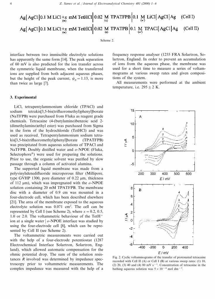
Fig. 2. Cyclic voltammograms of the transfer of protonated tetracainerecorded with Cell II (A) or Cell I (B) at various sweep rates: (1) 10,(2) 20, (3) 40 and (4) 80 mV s−1. Concentration of tetracaine in thebathing aqueous solution was 5×10⁻⁴ mol dm−3.
Z. Samec et al. / Journal of Electroanalytical Chemistry 481 (2000) 1–6 5
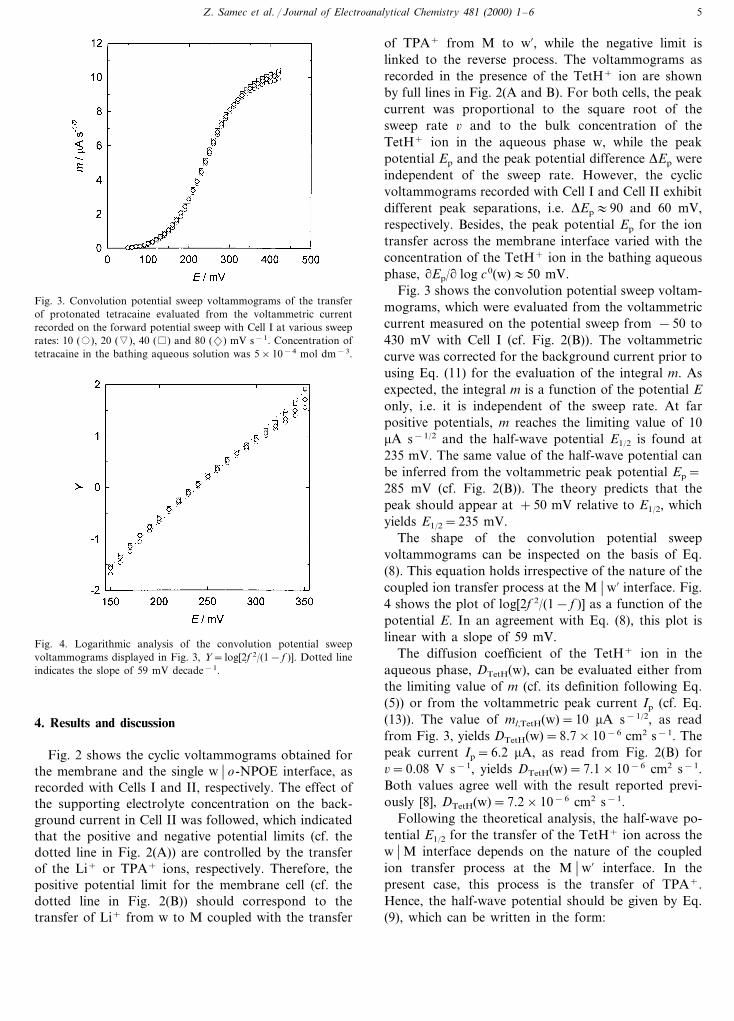
Fig. 3. Convolution potential sweep voltammograms of the transferof protonated tetracaine evaluated from the voltammetric currentrecorded on the forward potential sweep with Cell I at various sweeprates: 10 (�), 20 (�), 40 ( ) and 80 (2) mV s−1. Concentration oftetracaine in the bathing aqueous solution was 5×10⁻⁴ mol dm−3.
of TPA+ from M to w%, while the negative limit islinked to the reverse process. The voltammograms asrecorded in the presence of the TetH+ ion are shownby full lines in Fig. 2(A and B). For both cells, the peakcurrent was proportional to the square root of thesweep rate 6 and to the bulk concentration of theTetH+ ion in the aqueous phase w, while the peakpotential Ep and the peak potential difference DEp wereindependent of the sweep rate. However, the cyclicvoltammograms recorded with Cell I and Cell II exhibitdifferent peak separations, i.e. DEp:90 and 60 mV,respectively. Besides, the peak potential Ep for the iontransfer across the membrane interface varied with theconcentration of the TetH+ ion in the bathing aqueousphase, #Ep/# log c0(w):50 mV.
Fig. 3 shows the convolution potential sweep voltam-mograms, which were evaluated from the voltammetriccurrent measured on the potential sweep from −50 to430 mV with Cell I (cf. Fig. 2(B)). The voltammetriccurve was corrected for the background current prior tousing Eq. (11) for the evaluation of the integral m. Asexpected, the integral m is a function of the potential Eonly, i.e. it is independent of the sweep rate. At farpositive potentials, m reaches the limiting value of 10mA s−1/2 and the half-wave potential E1/2 is found at235 mV. The same value of the half-wave potential canbe inferred from the voltammetric peak potential Ep=285 mV (cf. Fig. 2(B)). The theory predicts that thepeak should appear at +50 mV relative to E1/2, whichyields E1/2=235 mV.
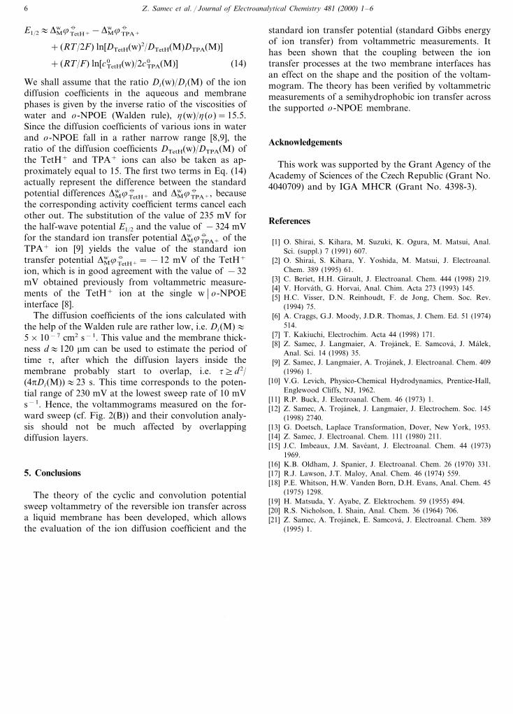
The shape of the convolution potential sweepvoltammograms can be inspected on the basis of Eq.(8). This equation holds irrespective of the nature of thecoupled ion transfer process at the M � w% interface. Fig.4 shows the plot of log[2f 2/(1− f )] as a function of thepotential E. In an agreement with Eq. (8), this plot islinear with a slope of 59 mV.
The diffusion coefficient of the TetH+ ion in theaqueous phase, DTetH(w), can be evaluated either fromthe limiting value of m (cf. its definition following Eq.(5)) or from the voltammetric peak current Ip (cf. Eq.(13)). The value of ml,TetH(w)=10 mA s−1/2, as readfrom Fig. 3, yields DTetH(w)=8.7×10⁻⁶ cm2 s−1. Thepeak current Ip=6.2 mA, as read from Fig. 2(B) for6=0.08 V s−1, yields DTetH(w)=7.1×10⁻⁶ cm2 s−1.Both values agree well with the result reported previ-ously [8], DTetH(w)=7.2×10⁻⁶ cm2 s−1.
Following the theoretical analysis, the half-wave po-tential E1/2 for the transfer of the TetH+ ion across thew � M interface depends on the nature of the coupledion transfer process at the M � w% interface. In thepresent case, this process is the transfer of TPA+.Hence, the half-wave potential should be given by Eq.(9), which can be written in the form:
Fig. 4. Logarithmic analysis of the convolution potential sweepvoltammograms displayed in Fig. 3, Y= log[2f 2/(1− f )]. Dotted lineindicates the slope of 59 mV decade−1.
4. Results and discussion
Fig. 2 shows the cyclic voltammograms obtained forthe membrane and the single w � o-NPOE interface, asrecorded with Cells I and II, respectively. The effect ofthe supporting electrolyte concentration on the back-ground current in Cell II was followed, which indicatedthat the positive and negative potential limits (cf. thedotted line in Fig. 2(A)) are controlled by the transferof the Li+ or TPA+ ions, respectively. Therefore, thepositive potential limit for the membrane cell (cf. thedotted line in Fig. 2(B)) should correspond to thetransfer of Li+ from w to M coupled with the transfer
Z. Samec et al. / Journal of Electroanalytical Chemistry 481 (2000) 1–66
E1/2:DwM86TetH+−Dw
M86TPA+
+ (RT/2F) ln[DTetH(w)2/DTetH(M)DTPA(M)]
+ (RT/F) ln[cTetH0 (w)/2cTPA
0 (M)] (14)
We shall assume that the ratio Di(w)/Di(M) of the iondiffusion coefficients in the aqueous and membranephases is given by the inverse ratio of the viscosities ofwater and o-NPOE (Walden rule), h(w)/h(o)=15.5.Since the diffusion coefficients of various ions in waterand o-NPOE fall in a rather narrow range [8,9], theratio of the diffusion coefficients DTetH(w)/DTPA(M) ofthe TetH+ and TPA+ ions can also be taken as ap-proximately equal to 15. The first two terms in Eq. (14)actually represent the difference between the standardpotential differences Dw
M86TetH+ and DwM86TPA+, because
the corresponding activity coefficient terms cancel eachother out. The substitution of the value of 235 mV forthe half-wave potential E1/2 and the value of −324 mVfor the standard ion transfer potential Dw
M86TPA+ of theTPA+ ion [9] yields the value of the standard iontransfer potential Dw
M86TetH+= −12 mV of the TetH+
ion, which is in good agreement with the value of −32mV obtained previously from voltammetric measure-ments of the TetH+ ion at the single w � o-NPOEinterface [8].
The diffusion coefficients of the ions calculated withthe help of the Walden rule are rather low, i.e. Di(M):5×10⁻⁷ cm2 s−1. This value and the membrane thick-ness d:120 mm can be used to estimate the period oftime t, after which the diffusion layers inside themembrane probably start to overlap, i.e. t]d2/(4pDi(M)):23 s. This time corresponds to the poten-tial range of 230 mV at the lowest sweep rate of 10 mVs−1. Hence, the voltammograms measured on the for-ward sweep (cf. Fig. 2(B)) and their convolution analy-sis should not be much affected by overlappingdiffusion layers.
5. Conclusions
The theory of the cyclic and convolution potentialsweep voltammetry of the reversible ion transfer acrossa liquid membrane has been developed, which allowsthe evaluation of the ion diffusion coefficient and the
standard ion transfer potential (standard Gibbs energyof ion transfer) from voltammetric measurements. Ithas been shown that the coupling between the iontransfer processes at the two membrane interfaces hasan effect on the shape and the position of the voltam-mogram. The theory has been verified by voltammetricmeasurements of a semihydrophobic ion transfer acrossthe supported o-NPOE membrane.
Acknowledgements
This work was supported by the Grant Agency of theAcademy of Sciences of the Czech Republic (Grant No.4040709) and by IGA MHCR (Grant No. 4398-3).
References
[1] O. Shirai, S. Kihara, M. Suzuki, K. Ogura, M. Matsui, Anal.Sci. (suppl.) 7 (1991) 607.
[2] O. Shirai, S. Kihara, Y. Yoshida, M. Matsui, J. Electroanal.Chem. 389 (1995) 61.
[3] C. Beriet, H.H. Girault, J. Electroanal. Chem. 444 (1998) 219.[4] V. Horvath, G. Horvai, Anal. Chim. Acta 273 (1993) 145.[5] H.C. Visser, D.N. Reinhoudt, F. de Jong, Chem. Soc. Rev.
(1994) 75.[6] A. Craggs, G.J. Moody, J.D.R. Thomas, J. Chem. Ed. 51 (1974)
514.[7] T. Kakiuchi, Electrochim. Acta 44 (1998) 171.[8] Z. Samec, J. Langmaier, A. Trojanek, E. Samcova, J. Malek,
Anal. Sci. 14 (1998) 35.[9] Z. Samec, J. Langmaier, A. Trojanek, J. Electroanal. Chem. 409
(1996) 1.[10] V.G. Levich, Physico-Chemical Hydrodynamics, Prentice-Hall,
Englewood Cliffs, NJ, 1962.[11] R.P. Buck, J. Electroanal. Chem. 46 (1973) 1.[12] Z. Samec, A. Trojanek, J. Langmaier, J. Electrochem. Soc. 145
(1998) 2740.[13] G. Doetsch, Laplace Transformation, Dover, New York, 1953.[14] Z. Samec, J. Electroanal. Chem. 111 (1980) 211.[15] J.C. Imbeaux, J.M. Saveant, J. Electroanal. Chem. 44 (1973)
1969.[16] K.B. Oldham, J. Spanier, J. Electroanal. Chem. 26 (1970) 331.[17] R.J. Lawson, J.T. Maloy, Anal. Chem. 46 (1974) 559.[18] P.E. Whitson, H.W. Vanden Born, D.H. Evans, Anal. Chem. 45
(1975) 1298.[19] H. Matsuda, Y. Ayabe, Z. Elektrochem. 59 (1955) 494.[20] R.S. Nicholson, I. Shain, Anal. Chem. 36 (1964) 706.[21] Z. Samec, A. Trojanek, E. Samcova, J. Electroanal. Chem. 389
(1995) 1.
.