Embed Size (px)
Citation preview
PCS Electronics www.pcs-electronics.com [email protected]
CYBER MAX FM 150W
CYBER MAX FM is an affordable high performance FM broadcasting exciter with SE4 (our DSP stereo encoder with extremely sharp filters, 19KHz notch filter, compressor, and limiter) and MAX PRO III (our latest high performance FM exciter with temperature protection and many other new technology enhancements). This unit was designed to offer excellent performance, spectral cleanliness and ruggedness for serious broadcasters looking for high quality at an accessible price. High quality components and manufacturing ensure 24/7 operation for years. FEATURES RF Output Power: 50-150W (130W-160W max typical), power is adjustable via display system Output connector: N Output Impedance: 50 Ohms Frequency Range: 87.5-108MHz PLL Steps: 50 KHz Frequency stability: +/- 50Hz Spurious/Harmonic rejection: Harmonics: -60dB typ., Spurious: -80dB typ. Audio Frequency Response: 35Hz-75 KHz @ -3dB Audio input: Balanced (XLR) or Unbalanced (RCA), 600 ohm Power Supply: Mains, 110V or 220V / 4T/250 fuse Stereo separation: >50dB typ. Audio low pass filters: Yes, with 19KHz notch filter! Precision pre-emphasis: 0, 50, or 75uS, selectable via display system
This manual covers: CYBER MAX FM 15W, CYBER MAX FM 40W, CYBER MAX FM 100W, CYBER MAX FM 150W and CYBER MAX FM 300W
2
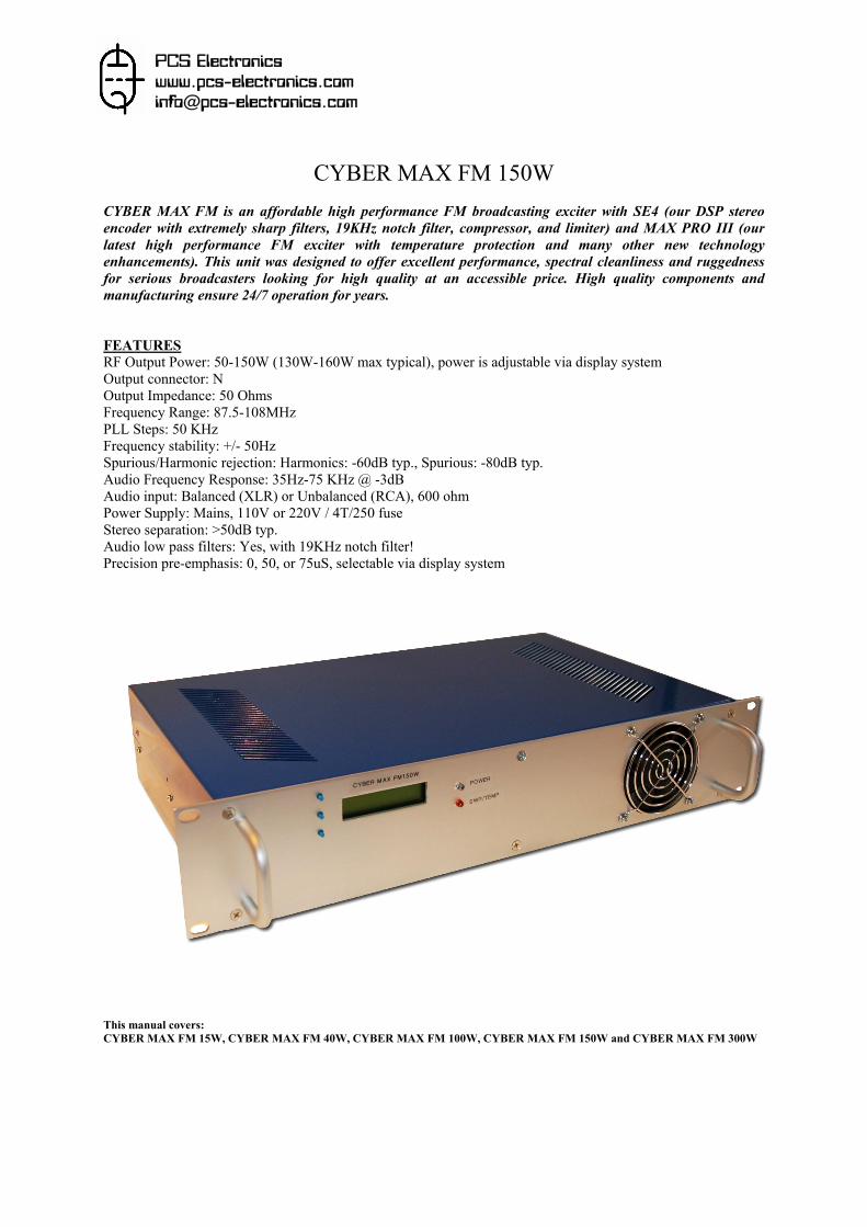
BEFORE YOU START... The mains power supply inside this unit is designed for 110V-240V 50/60Hz AC making this unit compatible with mains voltage in any country. It is, however, necessary to select proper voltage in the power supply. This switch is selected for you in the factory, but it is wise to check its position again on delivery to ensure proper operation and avoid any unnecessary damage. See picture below, switch is not directly visible here, but it can be found where the arrow points (at the side of the mains power supply unit):
CYBER MAX FM 150W: Mains voltage selection switch position We also recommend that you let the unit warm up for a couple hours, if necessary (winter). Also inspect the unit for any apparent damage, arising from shipping. Fasten any loose screws, if necessary. You will find some very useful tips, a forum and tips on antennas and hooking things together at http://www.pcs-electronics.com so it's generally a good place to check before putting your FM transmitter on the air. Here is what you need to use CYBER MAX FM: Antenna An antenna (J-pole, 5/8 Comet, 1/4 wave, broadband) up high makes up for lots of power...and is money well spent! Remember propagation at FM frequencies (88-108MHz) is virtually line-of-sight. City miles are longer than country miles; Forest miles are farther than desert miles. Low VSWR and antenna height alone can make up for lots of watts! Make sure you’re using the lowest possible power to tune your antenna to prevent any damage to the transmitter. High SWR (caused by badly tuned antenna) can damage your transmitter. For instructions regarding construction of antennas please see the end of this document or our website: http://www.pcs-electronics.com You should have realized by now that antenna was, is and will always be a crucial part of the system. Special care has to be taken! It is usually a good idea to place antenna away from your transmitter, power supply and
audio system. If you cannot meet these requirements, you could experience feedback and other RF problems. We cannot guarantee proper operation of CYBER MAX FM unless suitable antenna system is used! Interestingly, RF energy can make CD players and other digital devices go bezerk. Try placing 30W-driven antenna next to
yours, most of the modern audio gear is not RF shielded. Coaxial cable the common RG-58 from Radio Shack is NOT the best you can do and will lower your effective power out! Use it only for short runs. BELDEN makes terrific coax in various qualities and with very low loss (measured in dB’s…decibels)…figure 3 dB loss = 1/4 of your signal strength…either lost or gained. Watch out for the correct impedance…RG-8 and RG-58 have 50 Ohms. RG-59 and RG-6 (Low Loss Version of RG-59) have 75 Ohms. Most antennas are 50 Ohm ones. Check our web site for good coax. Don't buy more than you need to make the long run to your antenna and make up a few "jumpers" to go between your exciter, VSWR meter and your antenna as all you'll do is create a higher SWR and more line losses. Don't use cheap TV cable.
DO NOT POWER UP THIS UNIT WITHOUT A TUNED ANTENNA! BAD SWR CAN DAMAGE THE OUTPUT STAGE!
3
N connector comes between coaxial cable and your transmitter. It’s a standard connector. You might get it along with your antenna and cable. If your antenna comes with PL259 connector, use N to SO239 adapter. Audio equipment. For a start all you need is a simple CD player or a cassette deck. If you want that really professional sound, you will eventually need low noise audio mixer, good microphone, audio Limiter-compressor…. Behringer is a well known name for such equipment. Cheap stuff will give you noise, distortion, over-modulation etc. Consider using PC as your audio platform, get a good sound board and it will do mixing, MP3-playing, limiting, audio processing, CD-playing etc, all at a minimal cost (provided you already own a PC). HOOKING THINGS TOGETHER AND POWERING UP Antenna should be matched to 50ohms (it is best to use SWR meter to verify that). It is in fact recommended that you use dummy load the first time you power up your transmitter, until you make sure that everything is well and everything is working optimally. Output power should be adjusted to minimum at the beginning. Make sure your antenna or dummy load is connected before you turn on your transmitter. Failure to do so is likely to cause destruction of the final stage. Finally, set the main on/off switch at the back of the unit to off and connect the mains power supply cable (standard cable, not included with transmitter). Also make sure mains voltage switch inside the unit is set to your mains voltage (110V in the US, 220V in the EU). See above for more info about this. SETUP AND USE Connect dummy antenna, audio source and power. Turn the unit on. OK, now you should see the welcome message on the LCD. You will also hear a beep after power on. We suggest you press the menu button now, select POWER and set output power to minimum until you have verified your SWR is ok. If all appears to be ok, set the working frequency with UP/DOWN keys. It will take up to 10 seconds after changing the frequency for your transmitter to engage output stage again. This is normal behavior. Now turn on your MP3 player, CD audio player or other AUDIO source. Turn on any fm radio and turn the tuning dial until you hear the audio through the fm radio. You will need to adjust audio level so that the sound on the radio sounds natural and without distortion. Too much volume may sound good on your radio, but will sound horrible a few hundred meters from the transmitter! You shouldn’t sound louder then other FM stations; rather you should sound a bit quieter since you’re not using limiters/compressors (yet). When you sound as loud as other stations and you’re not using audio processing, you’re actually over modulating. Unfortunately many commercial stations over-modulate nowadays, it’s a sad fact. You may want to try a few different frequencies because of better reception in different areas. Some spots on the dial may work better than others. DSP functions of the audio processor unit can be displayed and adjusted via the menu system, explained at the end of this document. Setting DSP will take a bit of experimenting to get the best results (See appendix). You can now try to slowly increase the power. Keep listening to the radio, signal should remain strong and clean. Only use as much power as necessary for your application. Make sure to keep the slots on the cover free to allow free air exchange and cooling of the unit.
WARNING: PLEASE BE SURE THAT YOU ARE TUNING IN TO AN AREA ON YOUR LOCAL FM BAND THAT HAS NO STATION BROADCASTING ON IT, YOU DO NOT WANT TO INTERRUPT ANYONE ELSE'S LISTENTING TO LOCAL RADIO STATIONS, IT'S RUDE AND ALSO ILEGAL!
4
FRONT AND BACK PANEL
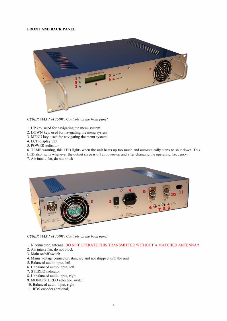
CYBER MAX FM 150W: Controls on the front panel 1. UP key, used for navigating the menu system 2. DOWN key, used for navigating the menu system 3. MENU key, used for navigating the menu system 4. LCD display unit 5. POWER indicator 6. TEMP warning, this LED lights when the unit heats up too much and automatically starts to shut down. This LED also lights whenever the output stage is off at power-up and after changing the operating frequency. 7. Air intake fan, do not block
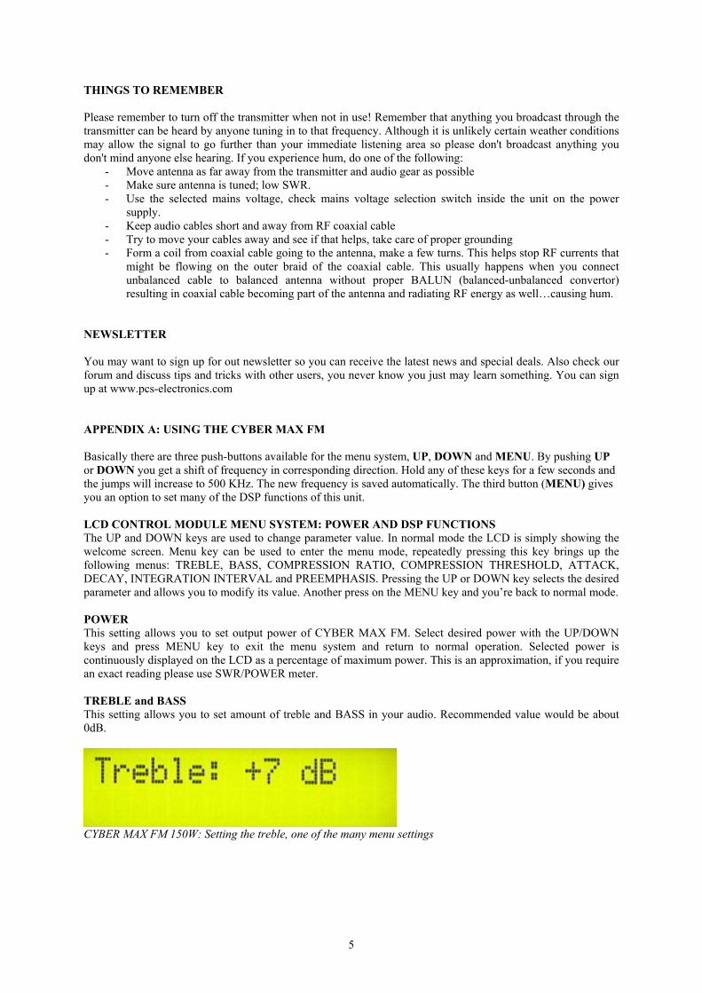
CYBER MAX FM 150W: Controls on the back panel 1. N connector, antenna. DO NOT OPERATE THIS TRANSMITTER WITHOUT A MATCHED ANTENNA!! 2. Air intake fan, do not block 3. Main on/off switch 4. Mains voltage connector, standard and not shipped with the unit 5. Balanced audio input, left 6. Unbalanced audio input, left 7. STEREO indicator 8. Unbalanced audio input, right 9. MONO/STEREO selection switch 10. Balanced audio input, right 11. RDS encoder (optional)
5
THINGS TO REMEMBER Please remember to turn off the transmitter when not in use! Remember that anything you broadcast through the transmitter can be heard by anyone tuning in to that frequency. Although it is unlikely certain weather conditions may allow the signal to go further than your immediate listening area so please don't broadcast anything you don't mind anyone else hearing. If you experience hum, do one of the following:
- Move antenna as far away from the transmitter and audio gear as possible - Make sure antenna is tuned; low SWR. - Use the selected mains voltage, check mains voltage selection switch inside the unit on the power
supply. - Keep audio cables short and away from RF coaxial cable - Try to move your cables away and see if that helps, take care of proper grounding - Form a coil from coaxial cable going to the antenna, make a few turns. This helps stop RF currents that
might be flowing on the outer braid of the coaxial cable. This usually happens when you connect unbalanced cable to balanced antenna without proper BALUN (balanced-unbalanced convertor) resulting in coaxial cable becoming part of the antenna and radiating RF energy as well…causing hum.
NEWSLETTER You may want to sign up for out newsletter so you can receive the latest news and special deals. Also check our forum and discuss tips and tricks with other users, you never know you just may learn something. You can sign up at www.pcs-electronics.com APPENDIX A: USING THE CYBER MAX FM Basically there are three push-buttons available for the menu system, UP, DOWN and MENU. By pushing UP or DOWN you get a shift of frequency in corresponding direction. Hold any of these keys for a few seconds and the jumps will increase to 500 KHz. The new frequency is saved automatically. The third button (MENU) gives you an option to set many of the DSP functions of this unit. LCD CONTROL MODULE MENU SYSTEM: POWER AND DSP FUNCTIONS The UP and DOWN keys are used to change parameter value. In normal mode the LCD is simply showing the welcome screen. Menu key can be used to enter the menu mode, repeatedly pressing this key brings up the following menus: TREBLE, BASS, COMPRESSION RATIO, COMPRESSION THRESHOLD, ATTACK, DECAY, INTEGRATION INTERVAL and PREEMPHASIS. Pressing the UP or DOWN key selects the desired parameter and allows you to modify its value. Another press on the MENU key and you’re back to normal mode. POWER This setting allows you to set output power of CYBER MAX FM. Select desired power with the UP/DOWN keys and press MENU key to exit the menu system and return to normal operation. Selected power is continuously displayed on the LCD as a percentage of maximum power. This is an approximation, if you require an exact reading please use SWR/POWER meter. TREBLE and BASS This setting allows you to set amount of treble and BASS in your audio. Recommended value would be about 0dB.
CYBER MAX FM 150W: Setting the treble, one of the many menu settings
6
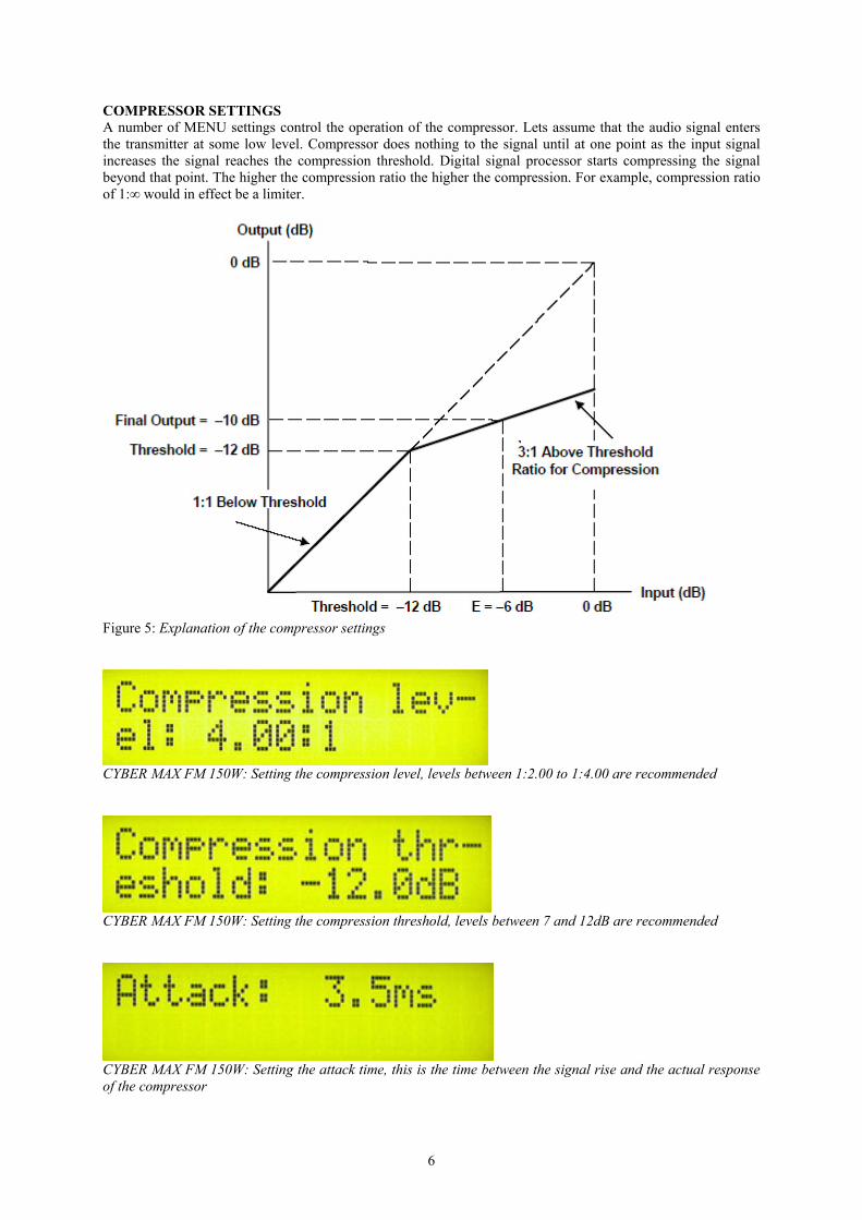
COMPRESSOR SETTINGS A number of MENU settings control the operation of the compressor. Lets assume that the audio signal enters the transmitter at some low level. Compressor does nothing to the signal until at one point as the input signal increases the signal reaches the compression threshold. Digital signal processor starts compressing the signal beyond that point. The higher the compression ratio the higher the compression. For example, compression ratio of 1:∞ would in effect be a limiter.
Figure 5: Explanation of the compressor settings
CYBER MAX FM 150W: Setting the compression level, levels between 1:2.00 to 1:4.00 are recommended
CYBER MAX FM 150W: Setting the compression threshold, levels between 7 and 12dB are recommended
CYBER MAX FM 150W: Setting the attack time, this is the time between the signal rise and the actual response of the compressor
7
CYBER MAX FM 150W: Setting the decay time, this is the time the compressor needs to respond to a decrease of the signal
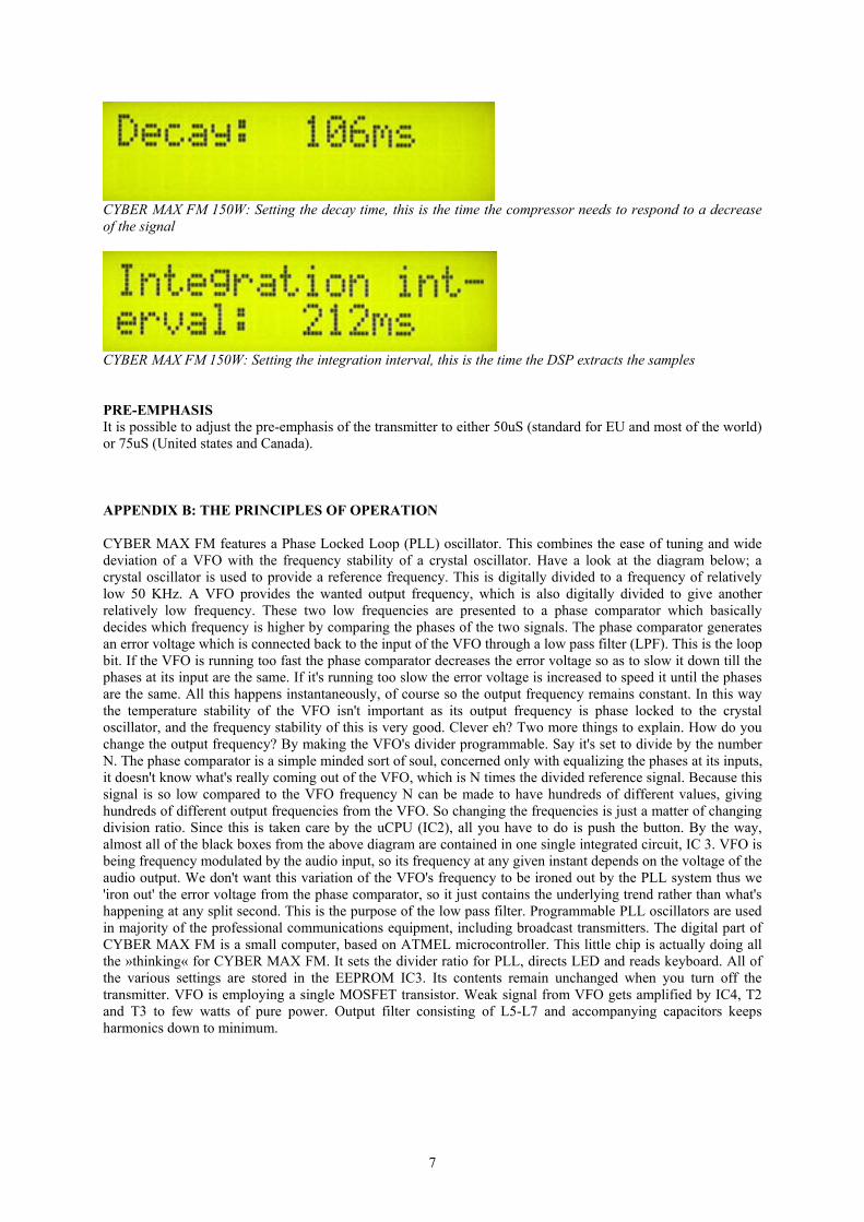
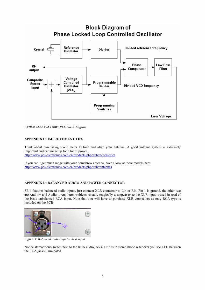
CYBER MAX FM 150W: Setting the integration interval, this is the time the DSP extracts the samples PRE-EMPHASIS It is possible to adjust the pre-emphasis of the transmitter to either 50uS (standard for EU and most of the world) or 75uS (United states and Canada). APPENDIX B: THE PRINCIPLES OF OPERATION CYBER MAX FM features a Phase Locked Loop (PLL) oscillator. This combines the ease of tuning and wide deviation of a VFO with the frequency stability of a crystal oscillator. Have a look at the diagram below; a crystal oscillator is used to provide a reference frequency. This is digitally divided to a frequency of relatively low 50 KHz. A VFO provides the wanted output frequency, which is also digitally divided to give another relatively low frequency. These two low frequencies are presented to a phase comparator which basically decides which frequency is higher by comparing the phases of the two signals. The phase comparator generates an error voltage which is connected back to the input of the VFO through a low pass filter (LPF). This is the loop bit. If the VFO is running too fast the phase comparator decreases the error voltage so as to slow it down till the phases at its input are the same. If it's running too slow the error voltage is increased to speed it until the phases are the same. All this happens instantaneously, of course so the output frequency remains constant. In this way the temperature stability of the VFO isn't important as its output frequency is phase locked to the crystal oscillator, and the frequency stability of this is very good. Clever eh? Two more things to explain. How do you change the output frequency? By making the VFO's divider programmable. Say it's set to divide by the number N. The phase comparator is a simple minded sort of soul, concerned only with equalizing the phases at its inputs, it doesn't know what's really coming out of the VFO, which is N times the divided reference signal. Because this signal is so low compared to the VFO frequency N can be made to have hundreds of different values, giving hundreds of different output frequencies from the VFO. So changing the frequencies is just a matter of changing division ratio. Since this is taken care by the uCPU (IC2), all you have to do is push the button. By the way, almost all of the black boxes from the above diagram are contained in one single integrated circuit, IC 3. VFO is being frequency modulated by the audio input, so its frequency at any given instant depends on the voltage of the audio output. We don't want this variation of the VFO's frequency to be ironed out by the PLL system thus we 'iron out' the error voltage from the phase comparator, so it just contains the underlying trend rather than what's happening at any split second. This is the purpose of the low pass filter. Programmable PLL oscillators are used in majority of the professional communications equipment, including broadcast transmitters. The digital part of CYBER MAX FM is a small computer, based on ATMEL microcontroller. This little chip is actually doing all the »thinking« for CYBER MAX FM. It sets the divider ratio for PLL, directs LED and reads keyboard. All of the various settings are stored in the EEPROM IC3. Its contents remain unchanged when you turn off the transmitter. VFO is employing a single MOSFET transistor. Weak signal from VFO gets amplified by IC4, T2 and T3 to few watts of pure power. Output filter consisting of L5-L7 and accompanying capacitors keeps harmonics down to minimum.
8
CYBER MAX FM 150W: PLL block diagram APPENDIX C: IMPROVEMENT TIPS Think about purchasing SWR meter to tune and align your antenna. A good antenna system is extremely important and can make up for a lot of power. http://www.pcs-electronics.com/en/products.php?sub=accessories If you can’t get much range with your homebrew antenna, have a look at these models here: http://www.pcs-electronics.com/en/products.php?sub=antennas APPENDIX D: BALANCED AUDIO AND POWER CONNECTOR SE-4 features balanced audio inputs, just connect XLR connector to Lin or Rin. Pin 1 is ground, the other two are Audio + and Audio -. Any hum problems usually magically disappear once the XLR input is used instead of the basic unbalanced RCA input. Note that you will have to purchase XLR connectors as only RCA type is included on the PCB
Figure 3: Balanced audio input – XLR input Notice stereo/mono switch next to the RCA audio jacks? Unit is in stereo mode whenever you see LED between the RCA jacks illuminated.
9
ALSO AVAILABLE FROM PCS ELECTRONICS
Directional antennas, mixer boards, audio processors, limiters, stereo enhancers, stereo encoders, electronic components, transistors, 15W boosters, 150, 300W and 750W amplifiers, 100W AM transmitters, stand-alone FM transmitters, RDS encoders and much much more… LIMITATION OF LIABILITY To the maximum extent permitted by applicable law, in no event shall PCS Electronics or its suppliers be liable for any special, incidental, indirect, or consequential damages whatsoever (including, without limitation, damages for loss of business profits, business interruption, loss of business information, or any other pecuniary loss) arising out of the use of or inability to use the PRODUCT, even if PCS Electronics has been advised of the possibility of such damages. In any case, PCS Electronics’ entire liability under any provision of this agreement shall be limited to the greater of the amount actually paid by you for the PRODUCT or U.S. $5.00; because some states and jurisdictions do not allow the exclusion or limitation of liability, the above limitation may not apply to you. LEGAL INFO CYBER MAX FM transmitters typically meet or exceed all broadcasting standards, but are not certified. If you want to certify them, you need to submit them to the appropriate authority for approval yourself. Therefore it might be illegal to operate this device in your county. Please consult local authorities before using CYBER MAX FM transmitters! THANK YOU FOR PURCHASING THE CYBERMAX FM TRANSMITTER! We hope you’ll enjoy it as much as we do and remember to tell your friends about it. Please feel free to send us your comments or make a post to our forum. From all of us we wish you happy broadcasting! PCS Electronics team www.pcs-electronics.com