Embed Size (px)
Citation preview

CX75SR, CX80 AND CX135SREXCAVATORS
OPERATOR’S MANUAL
NOTE: CNH America LLC reserves the right to make improvements in design or changes in specifications at any time without incurring any obligation to install them on units previously sold.
CASE TECHNICAL MANUALS
Manuals are available from your Dealer for the operation, service, and repair of your machine. For prompt convenient service, contact your Dealer for assistance in obtaining the manuals for your machine.
Your Dealer can expedite your order for Operator’s Manuals, Parts Catalogs, Service Manuals, and Maintenance records.
Always give the Machine Name, Model, and P.I.N. (Product Identification Number) or S.N. (Serial Number) of your machine so your Dealer can provide the correct manuals for your machine.
Part Number: 6-34551NA
CALIFORNIAPROPOSITION 65 WARNING
Diesel engine exhaust and some of its constituents are known to the State of California to cause cancer, birth defects, and other reproductive harm.
Battery post, terminals and related accessories contain lead and lead compounds. Wash hands after handling.
Copyright © 2004 CNH America LLC Bur 6-34551NAAll Rights Reserved Issued August, 2004
CASE and IH are registered trademarks of CNH America LLC
M171D
Safety Decals on this machine use the words Danger, Warning, or Caution, which are defined as follows:
● DANGER: Indicates an immediate hazardous situation that, if not avoided, will result in death or serious injury. The color associated with Danger is RED.
● WARNING: Indicates a potentially hazardous situation that, if not avoided, could result in death or serious injury. The color associated with Warning is ORANGE.
● CAUTION: Indicates a potentially hazardous situation which, if not avoided, may result in minor or moderate injury. It may also be used to alert against unsafe practices. The color associated with Caution is YELLOW.
If Safety Decals on this machine are ISO two panel Pictorial, decals are defined as follows:
● The first panel indicates the nature of the hazard.
● The second panel indicates the appropriate avoidance of the hazard.
● Background color is YELLOW
● Prohibition symbols such as and if used, are RED.
WARNING_01_NA
THIS SAFETY ALERT SYMBOL INDICATES IMPORTANT SAFETY MESSAGES IN THIS MANUAL. WHEN YOU SEE THIS SYMBOL, CAREFULLY READ THE MESSAGE THAT FOLLOWS AND BE ALERT TO THE POSSIBILITY OF DEATH OR SERIOUS INJURY
IMPROPER OPERATION OF THIS MACHINE CAN CAUSE DEATH OR SERIOUS INJURY. BEFORE USING THIS MACHINE, MAKE CERTAIN THAT EVERY OPERATOR:
● Is instructed in safe and proper use of the machine.
● Reads and understands the Manual(s) pertaining to the machine.
● Reads and understands ALL Safety Decals on the machine.
● Clears the area of other persons.
● Learns and practices safe use of machine controls in a safe, clear area before operating this machine on a job site.
It is your responsibility to observe pertinent laws and regulations and follow CNH America LLC instructions on machine operation and maintenance.
STOP
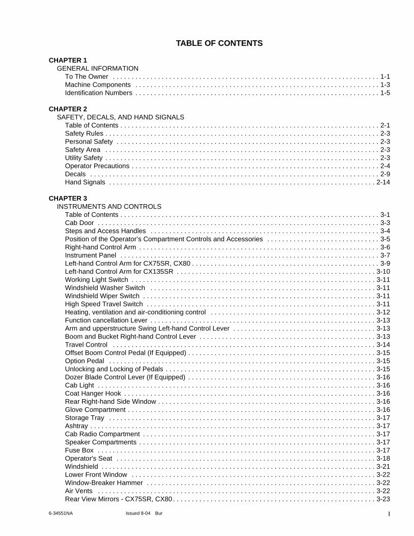
TABLE OF CONTENTS
CHAPTER 1GENERAL INFORMATION
To The Owner . . . . . . . . . . . . . . . . . . . . . . . . . . . . . . . . . . . . . . . . . . . . . . . . . . . . . . . . . . . . . . . . . . . . . . . 1-1Machine Components . . . . . . . . . . . . . . . . . . . . . . . . . . . . . . . . . . . . . . . . . . . . . . . . . . . . . . . . . . . . . . . . . 1-3Identification Numbers . . . . . . . . . . . . . . . . . . . . . . . . . . . . . . . . . . . . . . . . . . . . . . . . . . . . . . . . . . . . . . . . . 1-5
CHAPTER 2SAFETY, DECALS, AND HAND SIGNALS
Table of Contents . . . . . . . . . . . . . . . . . . . . . . . . . . . . . . . . . . . . . . . . . . . . . . . . . . . . . . . . . . . . . . . . . . . . . 2-1Safety Rules . . . . . . . . . . . . . . . . . . . . . . . . . . . . . . . . . . . . . . . . . . . . . . . . . . . . . . . . . . . . . . . . . . . . . . . . . 2-3Personal Safety . . . . . . . . . . . . . . . . . . . . . . . . . . . . . . . . . . . . . . . . . . . . . . . . . . . . . . . . . . . . . . . . . . . . . . 2-3Safety Area . . . . . . . . . . . . . . . . . . . . . . . . . . . . . . . . . . . . . . . . . . . . . . . . . . . . . . . . . . . . . . . . . . . . . . . . . 2-3Utility Safety . . . . . . . . . . . . . . . . . . . . . . . . . . . . . . . . . . . . . . . . . . . . . . . . . . . . . . . . . . . . . . . . . . . . . . . . . 2-3Operator Precautions . . . . . . . . . . . . . . . . . . . . . . . . . . . . . . . . . . . . . . . . . . . . . . . . . . . . . . . . . . . . . . . . . . 2-4Decals . . . . . . . . . . . . . . . . . . . . . . . . . . . . . . . . . . . . . . . . . . . . . . . . . . . . . . . . . . . . . . . . . . . . . . . . . . . . . 2-9Hand Signals . . . . . . . . . . . . . . . . . . . . . . . . . . . . . . . . . . . . . . . . . . . . . . . . . . . . . . . . . . . . . . . . . . . . . . . 2-14
CHAPTER 3INSTRUMENTS AND CONTROLS
Table of Contents . . . . . . . . . . . . . . . . . . . . . . . . . . . . . . . . . . . . . . . . . . . . . . . . . . . . . . . . . . . . . . . . . . . . . 3-1Cab Door . . . . . . . . . . . . . . . . . . . . . . . . . . . . . . . . . . . . . . . . . . . . . . . . . . . . . . . . . . . . . . . . . . . . . . . . . . . 3-3Steps and Access Handles . . . . . . . . . . . . . . . . . . . . . . . . . . . . . . . . . . . . . . . . . . . . . . . . . . . . . . . . . . . . . 3-4Position of the Operator’s Compartment Controls and Accessories . . . . . . . . . . . . . . . . . . . . . . . . . . . . . . 3-5Right-hand Control Arm . . . . . . . . . . . . . . . . . . . . . . . . . . . . . . . . . . . . . . . . . . . . . . . . . . . . . . . . . . . . . . . . 3-6Instrument Panel . . . . . . . . . . . . . . . . . . . . . . . . . . . . . . . . . . . . . . . . . . . . . . . . . . . . . . . . . . . . . . . . . . . . . 3-7Left-hand Control Arm for CX75SR, CX80 . . . . . . . . . . . . . . . . . . . . . . . . . . . . . . . . . . . . . . . . . . . . . . . . . . 3-9Left-hand Control Arm for CX135SR . . . . . . . . . . . . . . . . . . . . . . . . . . . . . . . . . . . . . . . . . . . . . . . . . . . . . 3-10Working Light Switch . . . . . . . . . . . . . . . . . . . . . . . . . . . . . . . . . . . . . . . . . . . . . . . . . . . . . . . . . . . . . . . . . 3-11Windshield Washer Switch . . . . . . . . . . . . . . . . . . . . . . . . . . . . . . . . . . . . . . . . . . . . . . . . . . . . . . . . . . . . 3-11Windshield Wiper Switch . . . . . . . . . . . . . . . . . . . . . . . . . . . . . . . . . . . . . . . . . . . . . . . . . . . . . . . . . . . . . . 3-11High Speed Travel Switch . . . . . . . . . . . . . . . . . . . . . . . . . . . . . . . . . . . . . . . . . . . . . . . . . . . . . . . . . . . . . 3-11Heating, ventilation and air-conditioning control . . . . . . . . . . . . . . . . . . . . . . . . . . . . . . . . . . . . . . . . . . . . 3-12Function cancellation Lever . . . . . . . . . . . . . . . . . . . . . . . . . . . . . . . . . . . . . . . . . . . . . . . . . . . . . . . . . . . . 3-13Arm and upperstructure Swing Left-hand Control Lever . . . . . . . . . . . . . . . . . . . . . . . . . . . . . . . . . . . . . . 3-13Boom and Bucket Right-hand Control Lever . . . . . . . . . . . . . . . . . . . . . . . . . . . . . . . . . . . . . . . . . . . . . . . 3-13Travel Control . . . . . . . . . . . . . . . . . . . . . . . . . . . . . . . . . . . . . . . . . . . . . . . . . . . . . . . . . . . . . . . . . . . . . . 3-14Offset Boom Control Pedal (If Equipped) . . . . . . . . . . . . . . . . . . . . . . . . . . . . . . . . . . . . . . . . . . . . . . . . . . 3-15Option Pedal . . . . . . . . . . . . . . . . . . . . . . . . . . . . . . . . . . . . . . . . . . . . . . . . . . . . . . . . . . . . . . . . . . . . . . . 3-15Unlocking and Locking of Pedals . . . . . . . . . . . . . . . . . . . . . . . . . . . . . . . . . . . . . . . . . . . . . . . . . . . . . . . . 3-15Dozer Blade Control Lever (If Equipped) . . . . . . . . . . . . . . . . . . . . . . . . . . . . . . . . . . . . . . . . . . . . . . . . . . 3-16Cab Light . . . . . . . . . . . . . . . . . . . . . . . . . . . . . . . . . . . . . . . . . . . . . . . . . . . . . . . . . . . . . . . . . . . . . . . . . . 3-16Coat Hanger Hook . . . . . . . . . . . . . . . . . . . . . . . . . . . . . . . . . . . . . . . . . . . . . . . . . . . . . . . . . . . . . . . . . . . 3-16Rear Right-hand Side Window . . . . . . . . . . . . . . . . . . . . . . . . . . . . . . . . . . . . . . . . . . . . . . . . . . . . . . . . . . 3-16Glove Compartment . . . . . . . . . . . . . . . . . . . . . . . . . . . . . . . . . . . . . . . . . . . . . . . . . . . . . . . . . . . . . . . . . . 3-16Storage Tray . . . . . . . . . . . . . . . . . . . . . . . . . . . . . . . . . . . . . . . . . . . . . . . . . . . . . . . . . . . . . . . . . . . . . . . 3-17Ashtray . . . . . . . . . . . . . . . . . . . . . . . . . . . . . . . . . . . . . . . . . . . . . . . . . . . . . . . . . . . . . . . . . . . . . . . . . . . . 3-17Cab Radio Compartment . . . . . . . . . . . . . . . . . . . . . . . . . . . . . . . . . . . . . . . . . . . . . . . . . . . . . . . . . . . . . . 3-17Speaker Compartments . . . . . . . . . . . . . . . . . . . . . . . . . . . . . . . . . . . . . . . . . . . . . . . . . . . . . . . . . . . . . . . 3-17Fuse Box . . . . . . . . . . . . . . . . . . . . . . . . . . . . . . . . . . . . . . . . . . . . . . . . . . . . . . . . . . . . . . . . . . . . . . . . . . 3-17Operator's Seat . . . . . . . . . . . . . . . . . . . . . . . . . . . . . . . . . . . . . . . . . . . . . . . . . . . . . . . . . . . . . . . . . . . . . 3-18Windshield . . . . . . . . . . . . . . . . . . . . . . . . . . . . . . . . . . . . . . . . . . . . . . . . . . . . . . . . . . . . . . . . . . . . . . . . . 3-21Lower Front Window . . . . . . . . . . . . . . . . . . . . . . . . . . . . . . . . . . . . . . . . . . . . . . . . . . . . . . . . . . . . . . . . . 3-22Window-Breaker Hammer . . . . . . . . . . . . . . . . . . . . . . . . . . . . . . . . . . . . . . . . . . . . . . . . . . . . . . . . . . . . . 3-22Air Vents . . . . . . . . . . . . . . . . . . . . . . . . . . . . . . . . . . . . . . . . . . . . . . . . . . . . . . . . . . . . . . . . . . . . . . . . . . 3-22Rear View Mirrors - CX75SR, CX80 . . . . . . . . . . . . . . . . . . . . . . . . . . . . . . . . . . . . . . . . . . . . . . . . . . . . . . 3-23
I6-34551NA Issued 8-04 Bur
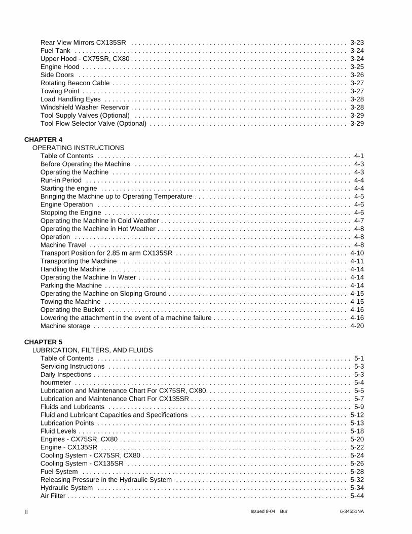
Rear View Mirrors CX135SR . . . . . . . . . . . . . . . . . . . . . . . . . . . . . . . . . . . . . . . . . . . . . . . . . . . . . . . . . . 3-23Fuel Tank . . . . . . . . . . . . . . . . . . . . . . . . . . . . . . . . . . . . . . . . . . . . . . . . . . . . . . . . . . . . . . . . . . . . . . . . . 3-24Upper Hood - CX75SR, CX80 . . . . . . . . . . . . . . . . . . . . . . . . . . . . . . . . . . . . . . . . . . . . . . . . . . . . . . . . . . 3-24Engine Hood . . . . . . . . . . . . . . . . . . . . . . . . . . . . . . . . . . . . . . . . . . . . . . . . . . . . . . . . . . . . . . . . . . . . . . . 3-25Side Doors . . . . . . . . . . . . . . . . . . . . . . . . . . . . . . . . . . . . . . . . . . . . . . . . . . . . . . . . . . . . . . . . . . . . . . . . 3-26Rotating Beacon Cable . . . . . . . . . . . . . . . . . . . . . . . . . . . . . . . . . . . . . . . . . . . . . . . . . . . . . . . . . . . . . . . 3-27Towing Point . . . . . . . . . . . . . . . . . . . . . . . . . . . . . . . . . . . . . . . . . . . . . . . . . . . . . . . . . . . . . . . . . . . . . . . 3-27Load Handling Eyes . . . . . . . . . . . . . . . . . . . . . . . . . . . . . . . . . . . . . . . . . . . . . . . . . . . . . . . . . . . . . . . . . 3-28Windshield Washer Reservoir . . . . . . . . . . . . . . . . . . . . . . . . . . . . . . . . . . . . . . . . . . . . . . . . . . . . . . . . . . 3-28Tool Supply Valves (Optional) . . . . . . . . . . . . . . . . . . . . . . . . . . . . . . . . . . . . . . . . . . . . . . . . . . . . . . . . . 3-29Tool Flow Selector Valve (Optional) . . . . . . . . . . . . . . . . . . . . . . . . . . . . . . . . . . . . . . . . . . . . . . . . . . . . . 3-29
CHAPTER 4OPERATING INSTRUCTIONS
Table of Contents . . . . . . . . . . . . . . . . . . . . . . . . . . . . . . . . . . . . . . . . . . . . . . . . . . . . . . . . . . . . . . . . . . . . 4-1Before Operating the Machine . . . . . . . . . . . . . . . . . . . . . . . . . . . . . . . . . . . . . . . . . . . . . . . . . . . . . . . . . . 4-3Operating the Machine . . . . . . . . . . . . . . . . . . . . . . . . . . . . . . . . . . . . . . . . . . . . . . . . . . . . . . . . . . . . . . . . 4-3Run-in Period . . . . . . . . . . . . . . . . . . . . . . . . . . . . . . . . . . . . . . . . . . . . . . . . . . . . . . . . . . . . . . . . . . . . . . . 4-4Starting the engine . . . . . . . . . . . . . . . . . . . . . . . . . . . . . . . . . . . . . . . . . . . . . . . . . . . . . . . . . . . . . . . . . . . 4-4Bringing the Machine up to Operating Temperature . . . . . . . . . . . . . . . . . . . . . . . . . . . . . . . . . . . . . . . . . . 4-5Engine Operation . . . . . . . . . . . . . . . . . . . . . . . . . . . . . . . . . . . . . . . . . . . . . . . . . . . . . . . . . . . . . . . . . . . . 4-6Stopping the Engine . . . . . . . . . . . . . . . . . . . . . . . . . . . . . . . . . . . . . . . . . . . . . . . . . . . . . . . . . . . . . . . . . . 4-6Operating the Machine in Cold Weather . . . . . . . . . . . . . . . . . . . . . . . . . . . . . . . . . . . . . . . . . . . . . . . . . . . 4-7Operating the Machine in Hot Weather . . . . . . . . . . . . . . . . . . . . . . . . . . . . . . . . . . . . . . . . . . . . . . . . . . . . 4-8Operation . . . . . . . . . . . . . . . . . . . . . . . . . . . . . . . . . . . . . . . . . . . . . . . . . . . . . . . . . . . . . . . . . . . . . . . . . . 4-8Machine Travel . . . . . . . . . . . . . . . . . . . . . . . . . . . . . . . . . . . . . . . . . . . . . . . . . . . . . . . . . . . . . . . . . . . . . . 4-8Transport Position for 2.85 m arm CX135SR . . . . . . . . . . . . . . . . . . . . . . . . . . . . . . . . . . . . . . . . . . . . . . 4-10Transporting the Machine . . . . . . . . . . . . . . . . . . . . . . . . . . . . . . . . . . . . . . . . . . . . . . . . . . . . . . . . . . . . . 4-11Handling the Machine . . . . . . . . . . . . . . . . . . . . . . . . . . . . . . . . . . . . . . . . . . . . . . . . . . . . . . . . . . . . . . . . 4-14Operating the Machine In Water . . . . . . . . . . . . . . . . . . . . . . . . . . . . . . . . . . . . . . . . . . . . . . . . . . . . . . . . 4-14Parking the Machine . . . . . . . . . . . . . . . . . . . . . . . . . . . . . . . . . . . . . . . . . . . . . . . . . . . . . . . . . . . . . . . . . 4-14Operating the Machine on Sloping Ground . . . . . . . . . . . . . . . . . . . . . . . . . . . . . . . . . . . . . . . . . . . . . . . . 4-15Towing the Machine . . . . . . . . . . . . . . . . . . . . . . . . . . . . . . . . . . . . . . . . . . . . . . . . . . . . . . . . . . . . . . . . . 4-15Operating the Bucket . . . . . . . . . . . . . . . . . . . . . . . . . . . . . . . . . . . . . . . . . . . . . . . . . . . . . . . . . . . . . . . . 4-16Lowering the attachment in the event of a machine failure . . . . . . . . . . . . . . . . . . . . . . . . . . . . . . . . . . . . 4-16Machine storage . . . . . . . . . . . . . . . . . . . . . . . . . . . . . . . . . . . . . . . . . . . . . . . . . . . . . . . . . . . . . . . . . . . . 4-20
CHAPTER 5LUBRICATION, FILTERS, AND FLUIDS
Table of Contents . . . . . . . . . . . . . . . . . . . . . . . . . . . . . . . . . . . . . . . . . . . . . . . . . . . . . . . . . . . . . . . . . . . . 5-1Servicing Instructions . . . . . . . . . . . . . . . . . . . . . . . . . . . . . . . . . . . . . . . . . . . . . . . . . . . . . . . . . . . . . . . . . 5-3Daily Inspections . . . . . . . . . . . . . . . . . . . . . . . . . . . . . . . . . . . . . . . . . . . . . . . . . . . . . . . . . . . . . . . . . . . . . 5-3hourmeter . . . . . . . . . . . . . . . . . . . . . . . . . . . . . . . . . . . . . . . . . . . . . . . . . . . . . . . . . . . . . . . . . . . . . . . . . . 5-4Lubrication and Maintenance Chart For CX75SR, CX80. . . . . . . . . . . . . . . . . . . . . . . . . . . . . . . . . . . . . . . 5-5Lubrication and Maintenance Chart For CX135SR . . . . . . . . . . . . . . . . . . . . . . . . . . . . . . . . . . . . . . . . . . . 5-7Fluids and Lubricants . . . . . . . . . . . . . . . . . . . . . . . . . . . . . . . . . . . . . . . . . . . . . . . . . . . . . . . . . . . . . . . . . 5-9Fluid and Lubricant Capacities and Specifications . . . . . . . . . . . . . . . . . . . . . . . . . . . . . . . . . . . . . . . . . . 5-12Lubrication Points . . . . . . . . . . . . . . . . . . . . . . . . . . . . . . . . . . . . . . . . . . . . . . . . . . . . . . . . . . . . . . . . . . . 5-13Fluid Levels . . . . . . . . . . . . . . . . . . . . . . . . . . . . . . . . . . . . . . . . . . . . . . . . . . . . . . . . . . . . . . . . . . . . . . . . 5-18Engines - CX75SR, CX80 . . . . . . . . . . . . . . . . . . . . . . . . . . . . . . . . . . . . . . . . . . . . . . . . . . . . . . . . . . . . . 5-20Engine - CX135SR . . . . . . . . . . . . . . . . . . . . . . . . . . . . . . . . . . . . . . . . . . . . . . . . . . . . . . . . . . . . . . . . . . 5-22Cooling System - CX75SR, CX80 . . . . . . . . . . . . . . . . . . . . . . . . . . . . . . . . . . . . . . . . . . . . . . . . . . . . . . . 5-24Cooling System - CX135SR . . . . . . . . . . . . . . . . . . . . . . . . . . . . . . . . . . . . . . . . . . . . . . . . . . . . . . . . . . . 5-26Fuel System . . . . . . . . . . . . . . . . . . . . . . . . . . . . . . . . . . . . . . . . . . . . . . . . . . . . . . . . . . . . . . . . . . . . . . . 5-28Releasing Pressure in the Hydraulic System . . . . . . . . . . . . . . . . . . . . . . . . . . . . . . . . . . . . . . . . . . . . . . 5-32Hydraulic System . . . . . . . . . . . . . . . . . . . . . . . . . . . . . . . . . . . . . . . . . . . . . . . . . . . . . . . . . . . . . . . . . . . 5-34Air Filter . . . . . . . . . . . . . . . . . . . . . . . . . . . . . . . . . . . . . . . . . . . . . . . . . . . . . . . . . . . . . . . . . . . . . . . . . . . 5-44
II Issued 8-04 Bur 6-34551NA
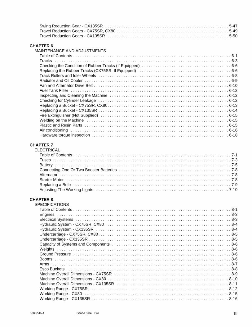
Swing Reduction Gear - CX135SR . . . . . . . . . . . . . . . . . . . . . . . . . . . . . . . . . . . . . . . . . . . . . . . . . . . . . . 5-47Travel Reduction Gears - CX75SR, CX80 . . . . . . . . . . . . . . . . . . . . . . . . . . . . . . . . . . . . . . . . . . . . . . . . . 5-49Travel Reduction Gears - CX135SR . . . . . . . . . . . . . . . . . . . . . . . . . . . . . . . . . . . . . . . . . . . . . . . . . . . . . 5-50
CHAPTER 6MAINTENANCE AND ADJUSTMENTS
Table of Contents . . . . . . . . . . . . . . . . . . . . . . . . . . . . . . . . . . . . . . . . . . . . . . . . . . . . . . . . . . . . . . . . . . . . . 6-1Tracks . . . . . . . . . . . . . . . . . . . . . . . . . . . . . . . . . . . . . . . . . . . . . . . . . . . . . . . . . . . . . . . . . . . . . . . . . . . . . 6-3Checking the Condition of Rubber Tracks (If Equipped) . . . . . . . . . . . . . . . . . . . . . . . . . . . . . . . . . . . . . . . 6-6Replacing the Rubber Tracks (CX75SR, If Equipped) . . . . . . . . . . . . . . . . . . . . . . . . . . . . . . . . . . . . . . . . . 6-6Track Rollers and Idler Wheels . . . . . . . . . . . . . . . . . . . . . . . . . . . . . . . . . . . . . . . . . . . . . . . . . . . . . . . . . . 6-8Radiator and Oil Cooler . . . . . . . . . . . . . . . . . . . . . . . . . . . . . . . . . . . . . . . . . . . . . . . . . . . . . . . . . . . . . . . . 6-9Fan and Alternator Drive Belt . . . . . . . . . . . . . . . . . . . . . . . . . . . . . . . . . . . . . . . . . . . . . . . . . . . . . . . . . . . 6-10Fuel Tank Filter . . . . . . . . . . . . . . . . . . . . . . . . . . . . . . . . . . . . . . . . . . . . . . . . . . . . . . . . . . . . . . . . . . . . . 6-12Inspecting and Cleaning the Machine . . . . . . . . . . . . . . . . . . . . . . . . . . . . . . . . . . . . . . . . . . . . . . . . . . . . 6-12Checking for Cylinder Leakage . . . . . . . . . . . . . . . . . . . . . . . . . . . . . . . . . . . . . . . . . . . . . . . . . . . . . . . . . 6-12Replacing a Bucket - CX75SR, CX80. . . . . . . . . . . . . . . . . . . . . . . . . . . . . . . . . . . . . . . . . . . . . . . . . . . . . 6-13Replacing a Bucket - CX135SR . . . . . . . . . . . . . . . . . . . . . . . . . . . . . . . . . . . . . . . . . . . . . . . . . . . . . . . . . 6-14Fire Extinguisher (Not Supplied) . . . . . . . . . . . . . . . . . . . . . . . . . . . . . . . . . . . . . . . . . . . . . . . . . . . . . . . . 6-15Welding on the Machine . . . . . . . . . . . . . . . . . . . . . . . . . . . . . . . . . . . . . . . . . . . . . . . . . . . . . . . . . . . . . . 6-15Plastic and Resin Parts . . . . . . . . . . . . . . . . . . . . . . . . . . . . . . . . . . . . . . . . . . . . . . . . . . . . . . . . . . . . . . . 6-15Air conditioning . . . . . . . . . . . . . . . . . . . . . . . . . . . . . . . . . . . . . . . . . . . . . . . . . . . . . . . . . . . . . . . . . . . . . 6-16Hardware torque inspection . . . . . . . . . . . . . . . . . . . . . . . . . . . . . . . . . . . . . . . . . . . . . . . . . . . . . . . . . . . . 6-18
CHAPTER 7ELECTRICAL
Table of Contents . . . . . . . . . . . . . . . . . . . . . . . . . . . . . . . . . . . . . . . . . . . . . . . . . . . . . . . . . . . . . . . . . . . . . 7-1Fuses . . . . . . . . . . . . . . . . . . . . . . . . . . . . . . . . . . . . . . . . . . . . . . . . . . . . . . . . . . . . . . . . . . . . . . . . . . . . . . 7-3Battery . . . . . . . . . . . . . . . . . . . . . . . . . . . . . . . . . . . . . . . . . . . . . . . . . . . . . . . . . . . . . . . . . . . . . . . . . . . . . 7-5Connecting One Or Two Booster Batteries . . . . . . . . . . . . . . . . . . . . . . . . . . . . . . . . . . . . . . . . . . . . . . . . . 7-8Alternator . . . . . . . . . . . . . . . . . . . . . . . . . . . . . . . . . . . . . . . . . . . . . . . . . . . . . . . . . . . . . . . . . . . . . . . . . . . 7-8Starter Motor . . . . . . . . . . . . . . . . . . . . . . . . . . . . . . . . . . . . . . . . . . . . . . . . . . . . . . . . . . . . . . . . . . . . . . . . 7-8Replacing a Bulb . . . . . . . . . . . . . . . . . . . . . . . . . . . . . . . . . . . . . . . . . . . . . . . . . . . . . . . . . . . . . . . . . . . . . 7-9Adjusting The Working Lights . . . . . . . . . . . . . . . . . . . . . . . . . . . . . . . . . . . . . . . . . . . . . . . . . . . . . . . . . . 7-10
CHAPTER 8SPECIFICATIONS
Table of Contents . . . . . . . . . . . . . . . . . . . . . . . . . . . . . . . . . . . . . . . . . . . . . . . . . . . . . . . . . . . . . . . . . . . . . 8-1Engines . . . . . . . . . . . . . . . . . . . . . . . . . . . . . . . . . . . . . . . . . . . . . . . . . . . . . . . . . . . . . . . . . . . . . . . . . . . . 8-3Electrical Systems . . . . . . . . . . . . . . . . . . . . . . . . . . . . . . . . . . . . . . . . . . . . . . . . . . . . . . . . . . . . . . . . . . . . 8-3Hydraulic System - CX75SR, CX80 . . . . . . . . . . . . . . . . . . . . . . . . . . . . . . . . . . . . . . . . . . . . . . . . . . . . . . . 8-4Hydraulic System - CX135SR . . . . . . . . . . . . . . . . . . . . . . . . . . . . . . . . . . . . . . . . . . . . . . . . . . . . . . . . . . . 8-4Undercarriage - CX75SR, CX80 . . . . . . . . . . . . . . . . . . . . . . . . . . . . . . . . . . . . . . . . . . . . . . . . . . . . . . . . . . 8-5Undercarriage - CX135SR . . . . . . . . . . . . . . . . . . . . . . . . . . . . . . . . . . . . . . . . . . . . . . . . . . . . . . . . . . . . . . 8-5Capacity of Systems and Components . . . . . . . . . . . . . . . . . . . . . . . . . . . . . . . . . . . . . . . . . . . . . . . . . . . . 8-6Weights . . . . . . . . . . . . . . . . . . . . . . . . . . . . . . . . . . . . . . . . . . . . . . . . . . . . . . . . . . . . . . . . . . . . . . . . . . . . 8-6Ground Pressure . . . . . . . . . . . . . . . . . . . . . . . . . . . . . . . . . . . . . . . . . . . . . . . . . . . . . . . . . . . . . . . . . . . . . 8-6Booms . . . . . . . . . . . . . . . . . . . . . . . . . . . . . . . . . . . . . . . . . . . . . . . . . . . . . . . . . . . . . . . . . . . . . . . . . . . . . 8-6Arms . . . . . . . . . . . . . . . . . . . . . . . . . . . . . . . . . . . . . . . . . . . . . . . . . . . . . . . . . . . . . . . . . . . . . . . . . . . . . . . 8-7Esco Buckets . . . . . . . . . . . . . . . . . . . . . . . . . . . . . . . . . . . . . . . . . . . . . . . . . . . . . . . . . . . . . . . . . . . . . . . . 8-8Machine Overall Dimensions - CX75SR . . . . . . . . . . . . . . . . . . . . . . . . . . . . . . . . . . . . . . . . . . . . . . . . . . . 8-9Machine Overall Dimensions - CX80 . . . . . . . . . . . . . . . . . . . . . . . . . . . . . . . . . . . . . . . . . . . . . . . . . . . . . 8-10Machine Overall Dimensions - CX135SR . . . . . . . . . . . . . . . . . . . . . . . . . . . . . . . . . . . . . . . . . . . . . . . . . 8-11Working Range - CX75SR . . . . . . . . . . . . . . . . . . . . . . . . . . . . . . . . . . . . . . . . . . . . . . . . . . . . . . . . . . . . . 8-12Working Range - CX80 . . . . . . . . . . . . . . . . . . . . . . . . . . . . . . . . . . . . . . . . . . . . . . . . . . . . . . . . . . . . . . . . 8-15Working Range - CX135SR . . . . . . . . . . . . . . . . . . . . . . . . . . . . . . . . . . . . . . . . . . . . . . . . . . . . . . . . . . . . 8-16
III6-34551NA Issued 8-04 Bur

CHAPTER 9INDEX
IV Issued 8-04 Bur 6-34551NA
CHAPTER 1 - GENERAL INFORMATION
Chapter 1
GENERAL INFORMATION
TO THE OWNER
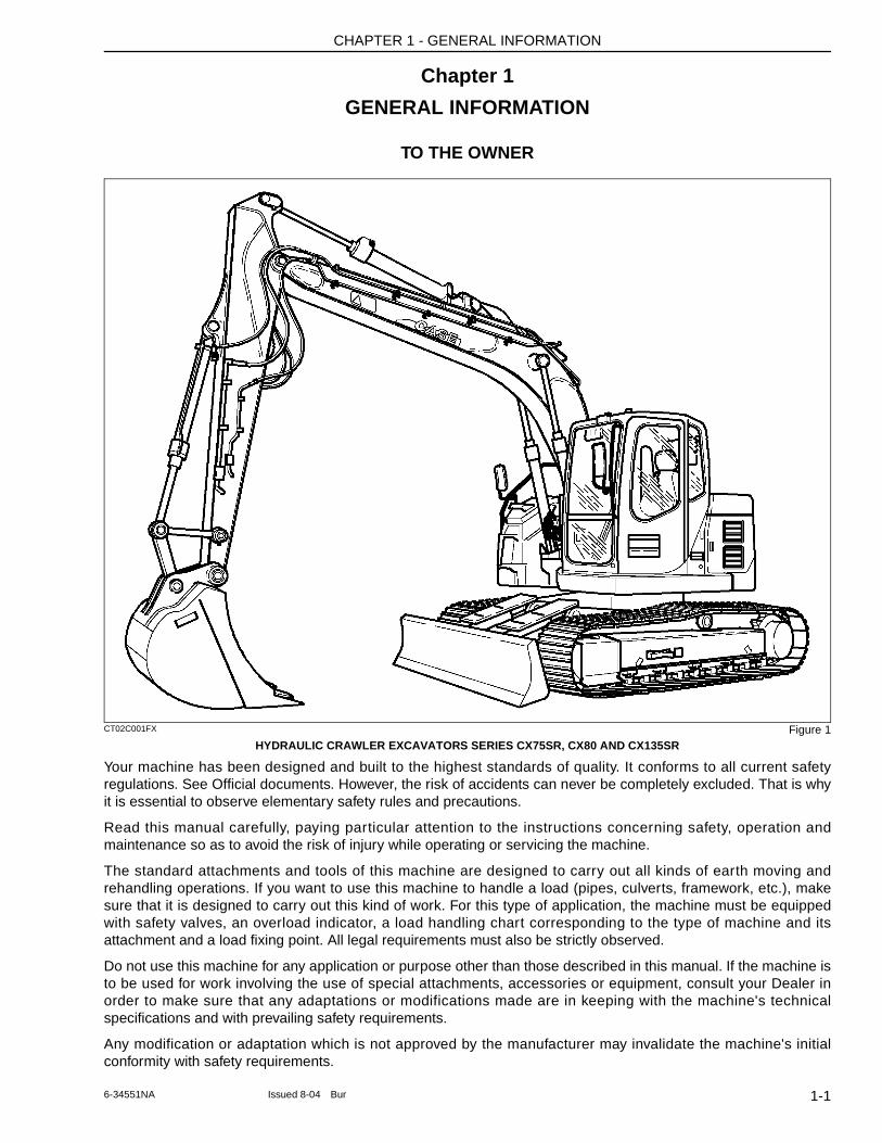
CT02C001FX Figure 1HYDRAULIC CRAWLER EXCAVATORS SERIES CX75SR, CX80 AND CX135SR
Your machine has been designed and built to the highest standards of quality. It conforms to all current safety regulations. See Official documents. However, the risk of accidents can never be completely excluded. That is why it is essential to observe elementary safety rules and precautions.
Read this manual carefully, paying particular attention to the instructions concerning safety, operation and maintenance so as to avoid the risk of injury while operating or servicing the machine.
The standard attachments and tools of this machine are designed to carry out all kinds of earth moving and rehandling operations. If you want to use this machine to handle a load (pipes, culverts, framework, etc.), make sure that it is designed to carry out this kind of work. For this type of application, the machine must be equipped with safety valves, an overload indicator, a load handling chart corresponding to the type of machine and its attachment and a load fixing point. All legal requirements must also be strictly observed.
Do not use this machine for any application or purpose other than those described in this manual. If the machine is to be used for work involving the use of special attachments, accessories or equipment, consult your Dealer in order to make sure that any adaptations or modifications made are in keeping with the machine's technical specifications and with prevailing safety requirements.
Any modification or adaptation which is not approved by the manufacturer may invalidate the machine's initial conformity with safety requirements.
1-16-34551NA Issued 8-04 Bur
CHAPTER 1 - GENERAL INFORMATION
The machine must undergo regular inspections, the frequency of which varies according to the type of use. Consult your Dealer.
Before permitting a new operator on this machine, make sure:
1. That the operator has received the necessary training on how to operate the machine correctly and safely in one of our training centres or from an approved organization.
2. That the operator has read and understood the instructions given in this manual.
Always keep this manual in the operator's compartment (in the seat back, behind the operator's seat). Make sure it is always complete and in good condition. If you wish to obtain extra copies, or copies in languages other than that of the country of use, consult your Dealer.
Your Dealer is at your disposal for any further information. He will also provide any after-sales service you may require, and genuine CASE spare parts, your guarantee of quality and match.
1-2 Issued 8-04 Bur 6-34551NA
CHAPTER 1 - GENERAL INFORMATION
MACHINE COMPONENTS
CT02C001 Figure 2
MAIN COMPONENTS
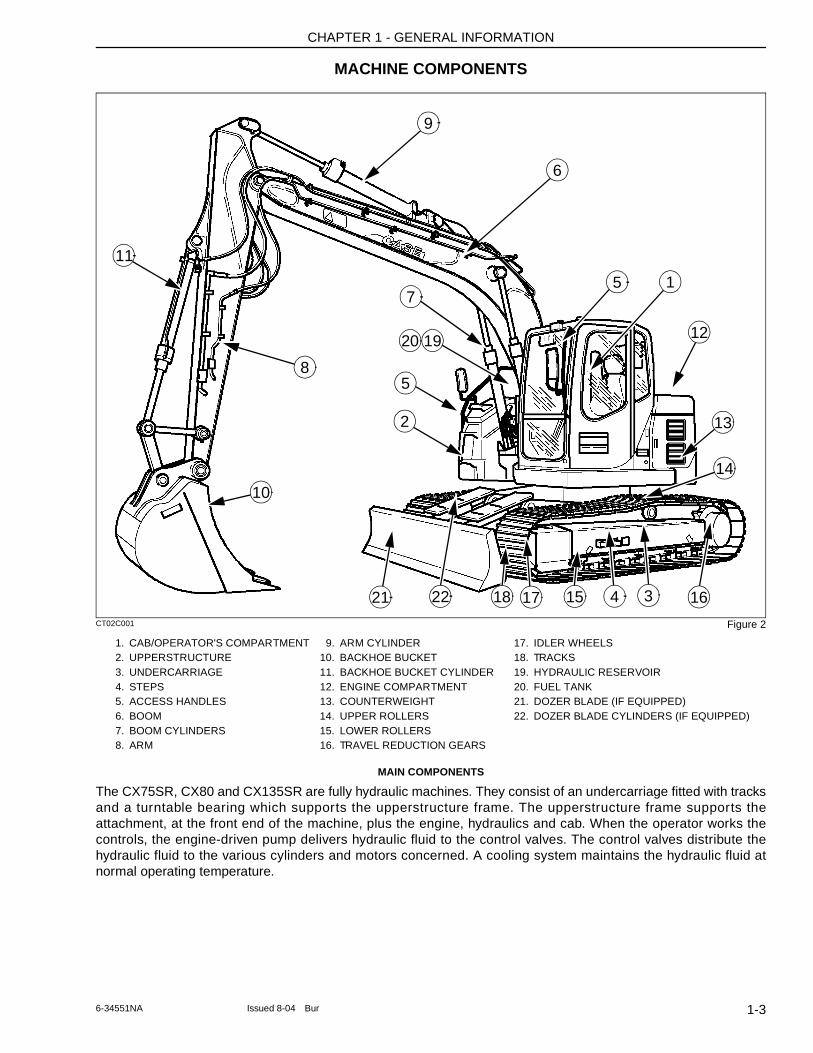
The CX75SR, CX80 and CX135SR are fully hydraulic machines. They consist of an undercarriage fitted with tracks and a turntable bearing which supports the upperstructure frame. The upperstructure frame supports the attachment, at the front end of the machine, plus the engine, hydraulics and cab. When the operator works the controls, the engine-driven pump delivers hydraulic fluid to the control valves. The control valves distribute the hydraulic fluid to the various cylinders and motors concerned. A cooling system maintains the hydraulic fluid at normal operating temperature.
1. CAB/OPERATOR'S COMPARTMENT 9. ARM CYLINDER 17. IDLER WHEELS2. UPPERSTRUCTURE 10. BACKHOE BUCKET 18. TRACKS3. UNDERCARRIAGE 11. BACKHOE BUCKET CYLINDER 19. HYDRAULIC RESERVOIR4. STEPS 12. ENGINE COMPARTMENT 20. FUEL TANK5. ACCESS HANDLES 13. COUNTERWEIGHT 21. DOZER BLADE (IF EQUIPPED)6. BOOM 14. UPPER ROLLERS 22. DOZER BLADE CYLINDERS (IF EQUIPPED)7. BOOM CYLINDERS 15. LOWER ROLLERS8. ARM 16. TRAVEL REDUCTION GEARS
6
1
12
10
7
8
11
2
9
13
16
14
18 17 15 4 32221
1920
5
5
1-36-34551NA Issued 8-04 Bur
CHAPTER 1 - GENERAL INFORMATION
RIGHT, LEFT, FRONT AND REAR OF THE MACHINE
CT02D269 Figure 3
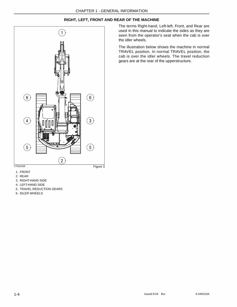
1. FRONT2. REAR3. RIGHT-HAND SIDE4. LEFT-HAND SIDE5. TRAVEL REDUCTION GEARS6. IDLER WHEELS
The terms Right-hand, Left-left, Front, and Rear are used in this manual to indicate the sides as they are seen from the operator's seat when the cab is over the idler wheels.
The illustration below shows the machine in normal TRAVEL position. In normal TRAVEL position, the cab is over the idler wheels. The travel reduction gears are at the rear of the upperstructure.
1
66
34
55
2
1-4 Issued 8-04 Bur 6-34551NA
CHAPTER 1 - GENERAL INFORMATION
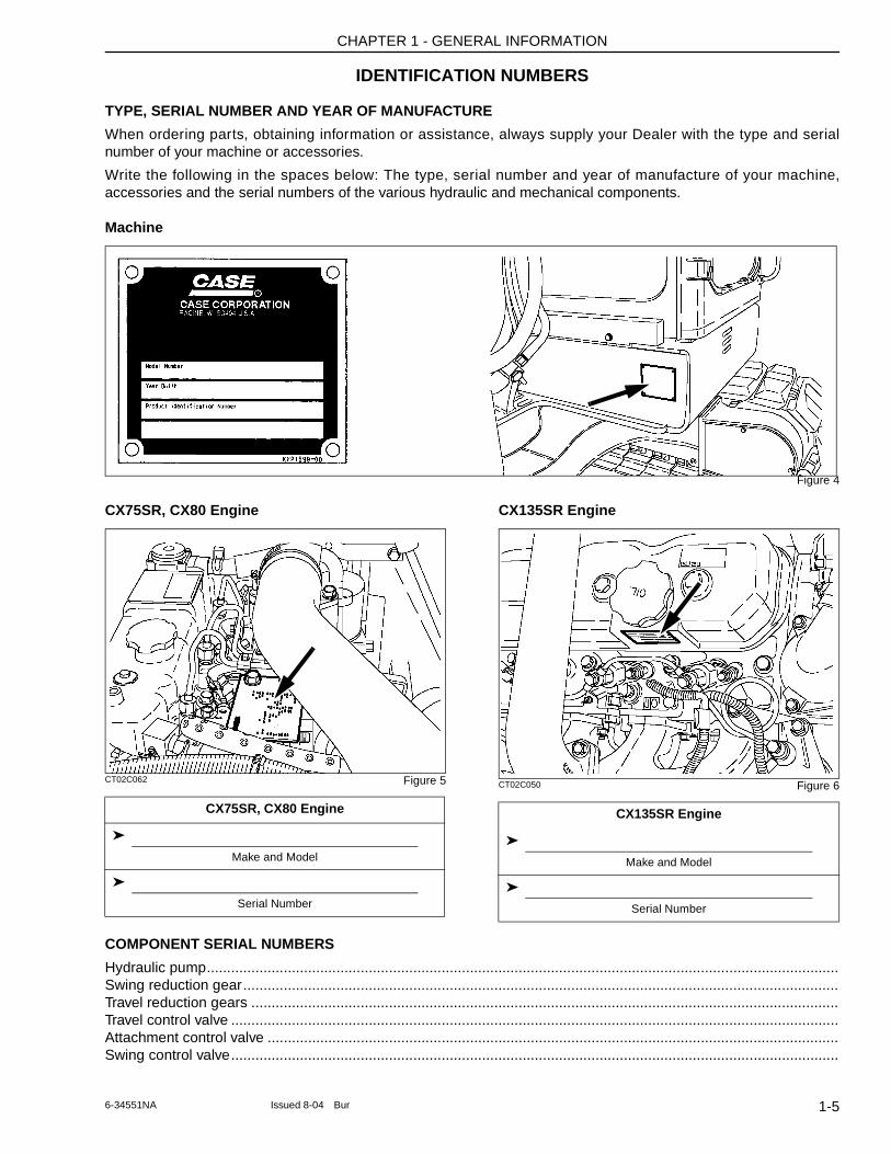
IDENTIFICATION NUMBERS
TYPE, SERIAL NUMBER AND YEAR OF MANUFACTURE
When ordering parts, obtaining information or assistance, always supply your Dealer with the type and serial number of your machine or accessories.
Write the following in the spaces below: The type, serial number and year of manufacture of your machine, accessories and the serial numbers of the various hydraulic and mechanical components.
Machine
Figure 4
CX75SR, CX80 Engine
CT02C062 Figure 5
CX135SR Engine
CT02C050 Figure 6
COMPONENT SERIAL NUMBERS
Hydraulic pump............................................................................................................................................................Swing reduction gear...................................................................................................................................................Travel reduction gears .................................................................................................................................................Travel control valve ......................................................................................................................................................Attachment control valve .............................................................................................................................................Swing control valve......................................................................................................................................................
CX75SR, CX80 Engine
➤
Make and Model
➤
Serial Number
CX135SR Engine
➤
Make and Model
➤
Serial Number
1-56-34551NA Issued 8-04 Bur

CHAPTER 1 - GENERAL INFORMATION
NOTES
1-6 Issued 8-04 Bur 6-34551NA
CHAPTER 2 - SAFETY, DECALS, AND HAND SIGNALS
Chapter 2
SAFETY, DECALS, AND HAND SIGNALS
TABLE OF CONTENTS
SAFETY RULES . . . . . . . . . . . . . . . . . . . . . . . . . . . . . . . . . . . . . . . . . . . . . . . . . . . . . . . . . . . . . . . . . . . . . . . . . . 2-3
PERSONAL SAFETY . . . . . . . . . . . . . . . . . . . . . . . . . . . . . . . . . . . . . . . . . . . . . . . . . . . . . . . . . . . . . . . . . . . . . . 2-3
SAFETY AREA . . . . . . . . . . . . . . . . . . . . . . . . . . . . . . . . . . . . . . . . . . . . . . . . . . . . . . . . . . . . . . . . . . . . . . . . . . . 2-3
UTILITY SAFETY . . . . . . . . . . . . . . . . . . . . . . . . . . . . . . . . . . . . . . . . . . . . . . . . . . . . . . . . . . . . . . . . . . . . . . . . . 2-3
OPERATOR PRECAUTIONS . . . . . . . . . . . . . . . . . . . . . . . . . . . . . . . . . . . . . . . . . . . . . . . . . . . . . . . . . . . . . . . 2-4Personnel . . . . . . . . . . . . . . . . . . . . . . . . . . . . . . . . . . . . . . . . . . . . . . . . . . . . . . . . . . . . . . . . . . . . . . . . . . . . . 2-4General . . . . . . . . . . . . . . . . . . . . . . . . . . . . . . . . . . . . . . . . . . . . . . . . . . . . . . . . . . . . . . . . . . . . . . . . . . . . . . 2-4Mounting and Dismounting Precautions . . . . . . . . . . . . . . . . . . . . . . . . . . . . . . . . . . . . . . . . . . . . . . . . . . . . . 2-4Starting and Stopping Precautions . . . . . . . . . . . . . . . . . . . . . . . . . . . . . . . . . . . . . . . . . . . . . . . . . . . . . . . . . . 2-5Operating Precautions . . . . . . . . . . . . . . . . . . . . . . . . . . . . . . . . . . . . . . . . . . . . . . . . . . . . . . . . . . . . . . . . . . . 2-5Maintenance Precautions . . . . . . . . . . . . . . . . . . . . . . . . . . . . . . . . . . . . . . . . . . . . . . . . . . . . . . . . . . . . . . . . . 2-6Fuel Handling Precautions . . . . . . . . . . . . . . . . . . . . . . . . . . . . . . . . . . . . . . . . . . . . . . . . . . . . . . . . . . . . . . . . 2-7Burn Prevention . . . . . . . . . . . . . . . . . . . . . . . . . . . . . . . . . . . . . . . . . . . . . . . . . . . . . . . . . . . . . . . . . . . . . . . . 2-7Hazardous Chemical Precautions . . . . . . . . . . . . . . . . . . . . . . . . . . . . . . . . . . . . . . . . . . . . . . . . . . . . . . . . . . 2-7Transporting Precautions . . . . . . . . . . . . . . . . . . . . . . . . . . . . . . . . . . . . . . . . . . . . . . . . . . . . . . . . . . . . . . . . . 2-8Wheel, Tire, and Track Safety . . . . . . . . . . . . . . . . . . . . . . . . . . . . . . . . . . . . . . . . . . . . . . . . . . . . . . . . . . . . . 2-8Roll-Over Protective Structure . . . . . . . . . . . . . . . . . . . . . . . . . . . . . . . . . . . . . . . . . . . . . . . . . . . . . . . . . . . . . 2-8Fire Extinguisher . . . . . . . . . . . . . . . . . . . . . . . . . . . . . . . . . . . . . . . . . . . . . . . . . . . . . . . . . . . . . . . . . . . . . . . 2-8Seat Belt Precautions . . . . . . . . . . . . . . . . . . . . . . . . . . . . . . . . . . . . . . . . . . . . . . . . . . . . . . . . . . . . . . . . . . . . 2-8Specific Precautions to this Machine . . . . . . . . . . . . . . . . . . . . . . . . . . . . . . . . . . . . . . . . . . . . . . . . . . . . . . . . 2-8
DECALS . . . . . . . . . . . . . . . . . . . . . . . . . . . . . . . . . . . . . . . . . . . . . . . . . . . . . . . . . . . . . . . . . . . . . . . . . . . . . . . . 2-9
HAND SIGNALS . . . . . . . . . . . . . . . . . . . . . . . . . . . . . . . . . . . . . . . . . . . . . . . . . . . . . . . . . . . . . . . . . . . . . . . . . 2-14
2-1Issued 8-04 Bur 6-34551NA

CHAPTER 2 - SAFETY, DECALS, AND HAND SIGNALS
NOTES
2-2 Issued 8-04 Bur 6-34551NA
CHAPTER 2 - SAFETY, DECALS, AND HAND SIGNALS
SAFETY RULES
M171C
Most accidents involving machine operating and maintenance can be avoided by following basic safety rules and precautions. Read and understand all the safety messages in this manual, the safety manual and the safety signs on the machine before you operate or service the machine. See your dealer if you have any questions.
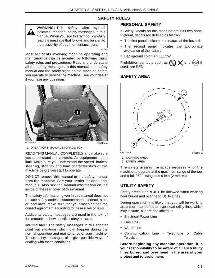
RD98K305 Figure 1
1. OPERATOR’S MANUAL STORAGE BOX
READ THIS MANUAL COMPLETELY and make sure you understand the controls. All equipment has a limit. Make sure you understand the speed, brakes, steering, stability and load characteristics of this machine before you start to operate.
DO NOT remove this manual or the safety manual from the machine. See your dealer for additional manuals. Also see the manual information on the inside of the rear cover of this manual.
The safety information given in this manual does not replace safety codes, insurance needs, federal, state or local laws. Make sure that your machine has the correct equipment according to these rules or laws.
Additional safety messages are used in the text of the manual to show specific safety hazards.
IMPORTANT: The safety messages in this chapter point out situations which can happen during the normal operation and maintenance of your machine. These safety messages also give possible ways of dealing with these conditions.
PERSONAL SAFETYIf Safety Decals on this machine are ISO two panel Pictorial, decals are defined as follows:
• The first panel indicates the nature of the hazard.
• The second panel indicates the appropriate avoidance of the hazard.
• Background color is YELLOW
Prohibition symbols such as and if used, are RED.
SAFETY AREA
CS97M019 Figure 2
1. WORKING AREA2. SAFETY AREA
The safety area is the space necessary for the machine to operate at the maximum range of the tool and a full 360° swing plus 6 feet (2 metres).
UTILITY SAFETYSafety precaution MUST be followed when working near buried and over head Utility Lines.
During operation it is likely that you will be working around or near buried or over head utility lines which may include, but are not limited to:
• Electrical Power Line
• Gas Line
• Water Line
• Communication Line - Telephone or Cable Television
Before beginning any machine operation, it is your responsibility to be aware of all such utility lines buried and over head in the area of your project and to avoid them.
WARNING: This safety alert symbol indicates important safety messages in this manual. When you see this symbol, carefully read the message that follows and be alert to the possibility of death or serious injury.
1
STOP
1
2
2-36-34551NA Issued 8-04 Bur
CHAPTER 2 - SAFETY, DECALS, AND HAND SIGNALS
ALWAYS have all local utility companies mark the location of their lines.
In U.S.A. and Canada call one of many “One Call System Director” services. If you do not know the local number, call the national number (U.S.A. and Canada only): 1-888-258-0808.
Check with local authorities for laws, regulations and/or strict penalties requiring you to locate and avoid existing utilities.
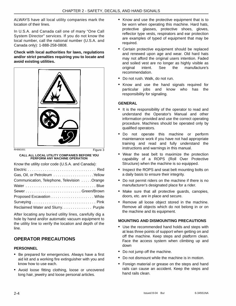
RH99G001 Figure 3
CALL ALL LOCAL UTILITY COMPANIES BEFORE YOU PERFORM ANY MACHINE OPERATION
Know the utility color code (U.S.A. and Canada):Electric . . . . . . . . . . . . . . . . . . . . . . . . . . . . . . . . RedGas, Oil, or Petroleum . . . . . . . . . . . . . . . . . . .YellowCommunication, Telephone, Television . . . . .OrangeWater . . . . . . . . . . . . . . . . . . . . . . . . . . . . . . . . . BlueSewer . . . . . . . . . . . . . . . . . . . . . . . . . . Green/BrownProposed Excavation . . . . . . . . . . . . . . . . . . . . WhiteSurveying . . . . . . . . . . . . . . . . . . . . . . . . . . . . . . PinkReclaimed Water and Slurry. . . . . . . . . . . . . . Purple
After locating any buried utility lines, carefully dig a hole by hand and/or automatic vacuum equipment to the utility line to verify the location and depth of the line.
OPERATOR PRECAUTIONS
PERSONNEL
• Be prepared for emergencies. Always have a first aid kit and a working fire extinguisher with you and know how to use each.
• Avoid loose fitting clothing, loose or uncovered long hair, jewelry and loose personal articles.
• Know and use the protective equipment that is to be worn when operating this machine. Hard hats, protective glasses, protective shoes, gloves, reflector type vests, respirators and ear protection are examples of typed of equipment that may be required.
• Certain protective equipment should be replaced and renewed upon age and wear. Old hard hats may not afford the original users intention. Faded and soiled vest are no longer as highly visible as original intent. See the manufacture’s recommendation.
• Do not rush. Walk, do not run.
• Know and use the hand signals required for particular jobs and know who has the responsibility for signaling.
GENERAL
• It is the responsibility of the operator to read and understand the Operator’s Manual and other information provided and use the correct operating procedure. Machines should be operated only by qualified operators.
• Do not operate this machine or perform maintenance work if you have not had appropriate training and read and fully understand the instructions and warnings in this manual.
• Wear the seat belt to maximize the protection capability of a ROPS (Roll Over Protective Structure) when the machine is so equipped.
• Inspect the ROPS and seat belt mounting bolts on a daily basis to ensure their integrity.
• Do not permit riders on the machine if there is no manufacturer’s designated place for a rider.
• Make sure that all protective guards, canopies, doors, etc. are in place and secure.
• Remove all loose object stored in the machine. Remove all objects which do not belong in or on the machine and its equipment.
MOUNTING AND DISMOUNTING PRECAUTIONS
• Use the recommended hand holds and steps with at leas three points of support when getting on and off the machine. Keep steps and platform clean. Face the access system when climbing up and down
• Do not jump off the machine.
• Do not dismount while the machine is in motion.
• Foreign material or grease on the steps and hand rails can cause an accident. Keep the steps and hand rails clean.
2-4 Issued 8-04 Bur 6-34551NA
CHAPTER 2 - SAFETY, DECALS, AND HAND SIGNALS
STARTING AND STOPPING PRECAUTIONS
• Walk around the machine and warn all personnel who may be servicing the machine or are in the machine path prior to starting. Do not start until all personnel are clearly away from the machine. Sound the horn, if equipped, before starting.
• Walk around the machines tool, attachment, or furthermost contact point to view operation danger area from the work site personnel view and angle.
• Check that the parking device is applied, place the transmission in neutral or park as specified by the manufacturer, and disengage the PTO, if so equipped, before starting the machine.
• Adjust, secure and latch the seat and fasten the seat belt before starting the machine.
• Start and operate the machine only from the operator’s station.
• Do not bypass the machine’s neutral-start system. The neutral-start system must be repaired if it malfunctions.
• Use jumper cables only in the recommended manner. Improper use can result in battery explosion or unexpected machine motion. Ventilate the battery area before using jumper cables. Make sure that using jumper cables will not interfere or harm electronic processing or computer devices.
• Do not operate the engine in an enclosed area without adequate ventilation.
• Park the machine on level ground whenever possible and apply the parking brake. On grades, park the machine with the wheels or track securely blocked.
• Before leaving the operator’s station, place the transmission in the park position as specified by the manufacturer, lower the equipment to the ground or put in the locked position, disengage the PTO, if so equipped, set the parking device and shut off the engine.
• Remove the starter key or disconnect switch when leaving the machine parked or unattended.
OPERATING PRECAUTIONS
• Check brakes, steering and other machine control devices in accordance with the manufacturers instructions prior to starting operation. Observe all gauges or warning instruments for proper operation. Operate all controls to insure proper operation. If any malfunctions are found, remove the starter key or disconnect switch key. Place a do not operate tag on the machine until the malfunction is corrected.
• If a failure that causes loss of control such as steering, service brakes or engine occurs, stop the machine motion as quickly as possible, remove the starter key or disconnect switch key. Place a do not operate tag on the machine and keep it securely parked until the malfunction is corrected or the machine can be safely towed.
• Understand the machine limitations and keep the machine under control.
• Operate and drive the machine with care and at speed compatible with conditions. Use extra caution when operating over rough ground, on slopes, and when turning.
• Note and avoid all hazards and obstructions such as ditches, underground lines, trees, cliffs, overhead electrical wires or areas where there is danger of a slide.
• Carry loads in recommended positions for maximum stability.
• Never lift loads in excess of capacity.
• Use the recommended machine ballast and counterweighting.
• Know and understand the job site traffic flow patterns and obey signalmen, road signs and flagmen.
• Know and understand that job site conditions may change on an hourly basis. Hills of dirt, debris or obstructions may grow and change from the time you began the day. It is your responsibility to monitor the changes and keep the machine, tools and attachments, etc. a safe distance.
• Watch for bystanders and never allow anyone to be under or to reach through the machine and its equipment while operating.
• Select a gear that will prevent excessive speed when going downhill. Do not coast downhill.
• When roading a machine, know and use the signaling devices required on the machine. Provide and escort for roading where required.
• On machines with independently operated wheel brakes, lock the brake pedals together when roading to provide equalized brake application.
• Use the recommended transport devices when roading the machine.
• Use the approved drawbar and / or attachment point when using the machine for towing. If a cable or chain is used, keep people away from the tow line.
• Before you operate at night, check that all lamps illuminate.
2-56-34551NA Issued 8-04 Bur
CHAPTER 2 - SAFETY, DECALS, AND HAND SIGNALS
• Engine exhaust fumes can cause death. If you operate this machine in an enclosed area, make sure there is ventilation to replace the exhaust fumes with fresh air.
• If your machine has a cab make sure that all windows are clean and that the windshield wipers work correctly.
• Check all controls in a clear area and make sure the machine is operating correctly.
• Dust, fog, smoke, etc., can decrease your vision and cause an accident. Stop the machine or decrease the speed until you can see.
• Contact with high voltage power lines, underground cables, etc., can cause serious injury or death from electrocution.
• Before you drive or operate in an area with high voltage lines, cables, or a power station, tell the power or utility company what you are going to do. You MUST HAVE THE POWER DISCONNECTED OR KEEP A SAFE WORKING DISTANCE from the lines, cables, or power station. Keep all parts of the machine at least 4.6 m (15 feet) away from the power source. You must also know any federal, state/provincial, or local safety codes or regulations that apply to the job site.
• If a part of the machine touches high voltage power:
1. Warn other workers NOT TO TOUCH THE MACHINE and to stay away from the machine.
2. If you can break contact, reverse the operation that caused contact with the high voltage power, and move the machine away from the danger area. If you cannot break contact stay in the machine until the utility company de-energizes the line and tells you that the power is off.
• If you have extreme conditions, such as a fire, etc., and you are forced to leave the machine, do not step off the machine. Jump as far from the machine as possible with your feet together and do not touch the ground with your hands.
• Do not operate the machine if you do not feel well. This can be dangerous for you and for the people around you.
• You must make a judgment if weather, road, or earth conditions will permit safe operation on a hill, ramp, or rough ground.
• Stay away from hazardous areas such as ditches, overhangs, etc. Walk around the work area before you start and look for hazards.
• Be alert and always know the location of all workers in your area. Keep all other persons completely away from your machine. Injury or death can result if you do not follow these instructions.
MAINTENANCE PRECAUTIONS
• Do not attempt repairs unless trained. Refer to manuals and experienced repair personnel for help.
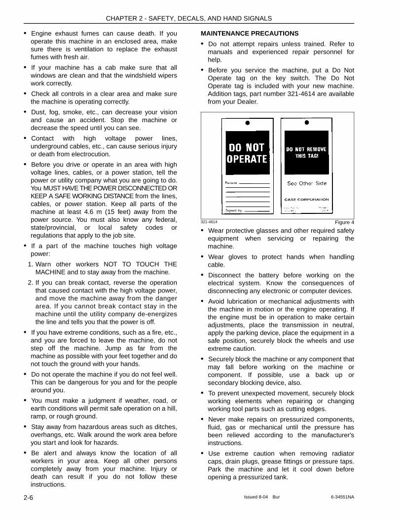
• Before you service the machine, put a Do Not Operate tag on the key switch. The Do Not Operate tag is included with your new machine. Addition tags, part number 321-4614 are available from your Dealer.
321-4614 Figure 4
• Wear protective glasses and other required safety equipment when servicing or repairing the machine.
• Wear gloves to protect hands when handling cable.
• Disconnect the battery before working on the electrical system. Know the consequences of disconnecting any electronic or computer devices.
• Avoid lubrication or mechanical adjustments with the machine in motion or the engine operating. If the engine must be in operation to make certain adjustments, place the transmission in neutral, apply the parking device, place the equipment in a safe position, securely block the wheels and use extreme caution.
• Securely block the machine or any component that may fall before working on the machine or component. If possible, use a back up or secondary blocking device, also.
• To prevent unexpected movement, securely block working elements when repairing or changing working tool parts such as cutting edges.
• Never make repairs on pressurized components, fluid, gas or mechanical until the pressure has been relieved according to the manufacturer’s instructions.
• Use extreme caution when removing radiator caps, drain plugs, grease fittings or pressure taps. Park the machine and let it cool down before opening a pressurized tank.
2-6 Issued 8-04 Bur 6-34551NA
CHAPTER 2 - SAFETY, DECALS, AND HAND SIGNALS
• Release all pressure before working on systems which have an accumulator. Use a piece of cardboard, newspaper, or wood to check for pressurized leaks to prevent fluid penetrating the skin. Pressurize accumulators with the proper gas according to manufacturers. recommendations.
• When inflating tires, use a self-attaching inflation chuck with remote shutoff and stand clear of the tire. Position yourself beside the tire and not beside the rim.
• When absolutely necessary to tow the machine, do not exceed the recommended towing speed. Be sure the towing machine has sufficient braking capacity to stop the towed load. If the towed machine cannot be braked, a towbar must be used or two towing machines must be used. - one in front pulling and one in the rear to act as a brake. Avoid towing over long distances.
• Observe proper maintenance procedures.
• Whenever servicing or replacing hardened pins, etc., use a brass drift or other suitable material between the hammer and pin. Alt: Use a brass hammer, drift or suitable material on the pin, etc.
• Keep the brakes and steering systems in good operating condition.
• Replace all missing, illegible or damaged safety signs. Keep all safety signs clean.
FUEL HANDLING PRECAUTIONS
• Do not smoke or permit open flames while fueling or near fueling operations.
• Never remove the fuel cap or refuel gasoline engine powered machines with the engine running or hot. Never allow fuel to spill on hot machine components. Never allow fuel to spill on the environment.
• To avoid spilling fuel maintain control of the fuel filler nozzle when filling the tank.
• Do not fill the fuel tank completely to the top. Allow room for expansion.
• Clean up spilled fuel immediately and dispose of contaminated material in an environmentally correct manner.
• Tighten the fuel tank cap securely. Should the fuel cap be lost, replace it only with the original manufacturers approved cap. Use of a non-approved cap without proper venting may result in pressurization of the tank.
• Never use fuel for cleaning purposes.
• Use the correct fuel grade for the operating season.
BURN PREVENTION
M144B
• When the battery electrolyte is frozen, the battery can explode if, you try to charge the battery, or you try to jump start and run the engine. To prevent the battery electrolyte from freezing, try to keep the battery at full charge. If you do not follow these instructions, you or others in the area can be injured
• Hot coolant can spray out if the radiator cap is removed. To remove the radiator cap, let the cooling system cool, turn to the first notch, wait until the pressure is released, then remove the radiator cap.
HAZARDOUS CHEMICAL PRECAUTIONS
• If you are exposed to or come in contact with hazardous chemicals you can be seriously injured. The fluids, lubricants, paints, adhesives, coolants, etc., used with your machine can be hazardous.
• Material Safety Data Sheets (MSDS) provide information about the chemical substances within a product, safe handling procedures, first aid measures and procedures to be taken when the product is accidentally spilled or released. MSDS are available from your dealer.
• Before you service your machine, check the MSDS for each fluid, lubricant, etc., used in this machine. This information indicates what the risks are and how to service the machine safely. Follow this information when servicing the machine.
• Before you service this machine and before you dispose of the old fluids and lubricants, always remember the environment. DO NOT put oil or fluids into the ground or into containers that can leak.
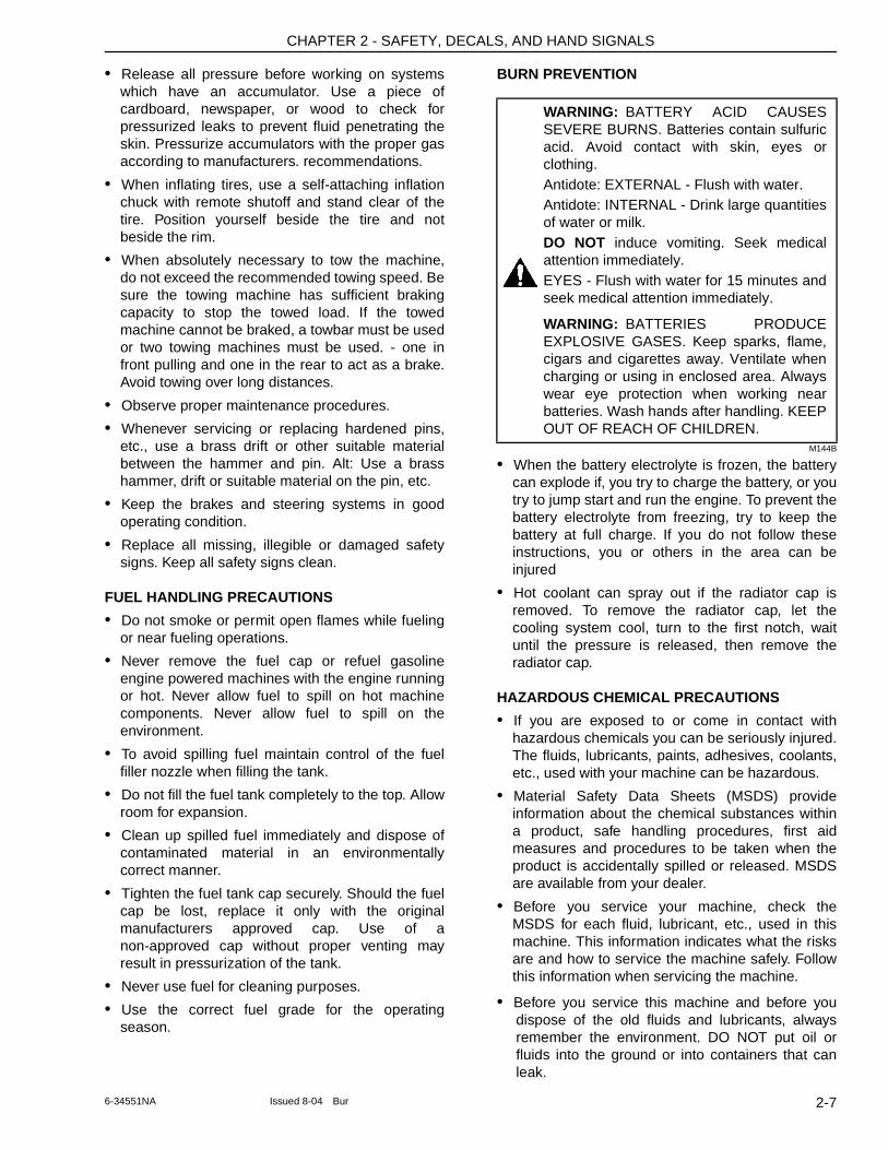
WARNING: BATTERY ACID CAUSES SEVERE BURNS. Batteries contain sulfuric acid. Avoid contact with skin, eyes or clothing.Antidote: EXTERNAL - Flush with water.Antidote: INTERNAL - Drink large quantities of water or milk. DO NOT induce vomiting. Seek medical attention immediately.EYES - Flush with water for 15 minutes and seek medical attention immediately.
WARNING: BATTERIES PRODUCE EXPLOSIVE GASES. Keep sparks, flame, cigars and cigarettes away. Ventilate when charging or using in enclosed area. Always wear eye protection when working near batteries. Wash hands after handling. KEEP OUT OF REACH OF CHILDREN.
2-76-34551NA Issued 8-04 Bur
CHAPTER 2 - SAFETY, DECALS, AND HAND SIGNALS
• Check with your local environmental or recycling center or your dealer for correct disposal information.
TRANSPORTING PRECAUTIONS
• Know the rules, laws, and safety equipment necessary for transporting this machine on a road or highway.
WHEEL, TIRE, AND TRACK SAFETY
• Explosive separation of the tire and/or rim parts can cause injury or death. When tire service is necessary, have a qualified tire mechanic service the tire.
ROLL-OVER PROTECTIVE STRUCTURE
• Do NOT modify the ROPS in any manner. Unauthorized modifications such as welding, drilling, cutting, or adding attachments can weaken the structure and reduce your protection. Replace ROPS if it is subjected to roll-over or damage. Do not attempt to repair.
FIRE EXTINGUISHER
It is recommended that you have a fire extinguisher on your machine. The fire extinguisher shown is available from your dealer and can be installed on the machine.
SEAT BELT PRECAUTIONS
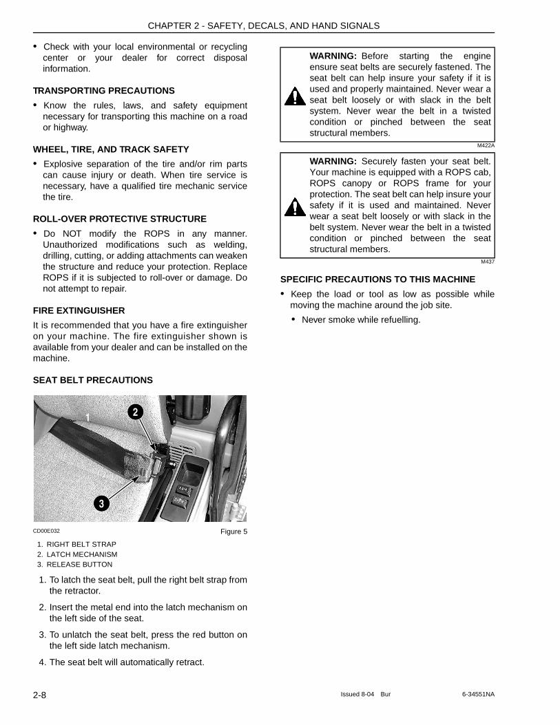
CD00E032 Figure 5
1. RIGHT BELT STRAP2. LATCH MECHANISM3. RELEASE BUTTON
1. To latch the seat belt, pull the right belt strap from the retractor.
2. Insert the metal end into the latch mechanism on the left side of the seat.
3. To unlatch the seat belt, press the red button on the left side latch mechanism.
4. The seat belt will automatically retract.
M422A
M437
SPECIFIC PRECAUTIONS TO THIS MACHINE
• Keep the load or tool as low as possible while moving the machine around the job site.
• Never smoke while refuelling.
1 2
3
WARNING: Before starting the engine ensure seat belts are securely fastened. The seat belt can help insure your safety if it is used and properly maintained. Never wear a seat belt loosely or with slack in the belt system. Never wear the belt in a twisted condition or pinched between the seat structural members.
WARNING: Securely fasten your seat belt. Your machine is equipped with a ROPS cab, ROPS canopy or ROPS frame for your protection. The seat belt can help insure your safety if it is used and maintained. Never wear a seat belt loosely or with slack in the belt system. Never wear the belt in a twisted condition or pinched between the seat structural members.
2-8 Issued 8-04 Bur 6-34551NA
CHAPTER 2 - SAFETY, DECALS, AND HAND SIGNALS
DECALS
NOTE: When you clean the decals, use only a cloth, water and soap. Do not use solvents, gasoline, etc.
NOTE: This chapter only covers decals relating to safety and machine operation and servicing. For information on all decals for the machine, consult your authorized dealer.
KHP1537-00 Figure 6
Th is 3 pane l deca l exp la ins the Danger o f electrocution, the impor tance of reading and understanding the operator’s manual and that attachment interference may cause damage to the operator’s compartment.
BS00M141 Figure 7
This decal warns of Danger and to keep clear of swinging upperstructure to prevent serious bodily injury.
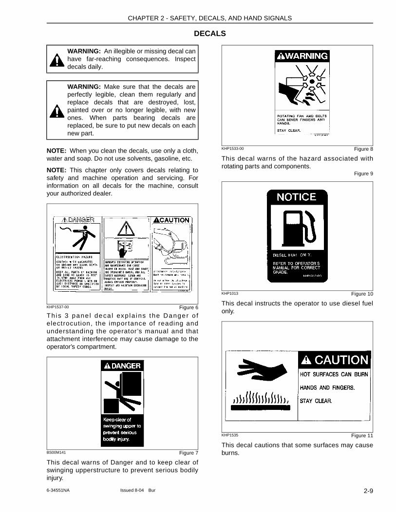
KHP1533-00 Figure 8
This decal warns of the hazard associated with rotating parts and components.
Figure 9
KHP1013 Figure 10
This decal instructs the operator to use diesel fuel only.
KHP1535 Figure 11
This decal cautions that some surfaces may cause burns.
WARNING: An illegible or missing decal can have far-reaching consequences. Inspect decals daily.
WARNING: Make sure that the decals are perfectly legible, clean them regularly and replace decals that are destroyed, lost, painted over or no longer legible, with new ones. When parts bearing decals are replaced, be sure to put new decals on each new part.
2-96-34551NA Issued 8-04 Bur
CHAPTER 2 - SAFETY, DECALS, AND HAND SIGNALS
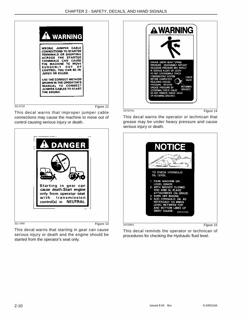
321-6718 Figure 12
This decal warns that improper jumper cable connections may cause the machine to move out of control causing serious injury or death.
321-7040 Figure 13
This decal warns that starting in gear can cause serious injury or death and the engine should be started from the operator’s seat only.
167327A1 Figure 14
This decal warns the operator or technican that grease may be under heavy pressure and cause serious injury or death.
167328A1 Figure 15
This decal reminds the operator or technican of procedures for checking the Hydraulic fluid level.
2-10 Issued 8-04 Bur 6-34551NA
CHAPTER 2 - SAFETY, DECALS, AND HAND SIGNALS
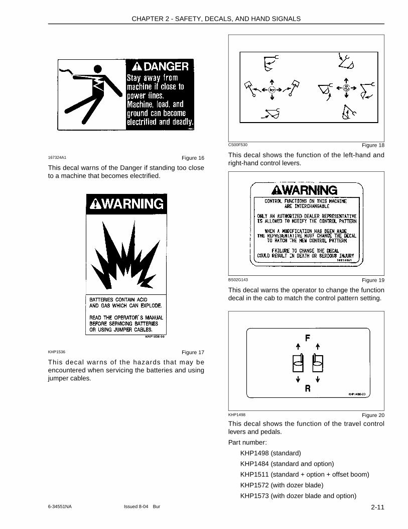
167324A1 Figure 16
This decal warns of the Danger if standing too close to a machine that becomes electrified.
KHP1536 Figure 17
This decal warns of the hazards that may be encountered when servicing the batteries and using jumper cables.
CS00F530 Figure 18
This decal shows the function of the left-hand and right-hand control levers.
BS02G143 Figure 19
This decal warns the operator to change the function decal in the cab to match the control pattern setting.
KHP1498 Figure 20
This decal shows the function of the travel control levers and pedals.
Part number:
KHP1498 (standard)
KHP1484 (standard and option)
KHP1511 (standard + option + offset boom)
KHP1572 (with dozer blade)
KHP1573 (with dozer blade and option)
2-116-34551NA Issued 8-04 Bur
CHAPTER 2 - SAFETY, DECALS, AND HAND SIGNALS
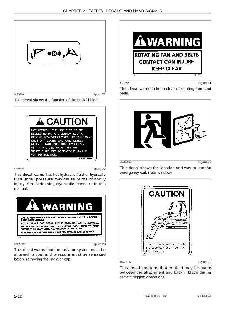
KHP0859 Figure 21
This decal shows the function of the backfill blade.
KHP1542 Figure 22
This decal warns that hot hydraulic fluid or hydraulic fluid under pressure may cause burns or bodily injury. See Releasing Hydraulic Pressure in this manual.
CT02C010 Figure 23
This decal warns that the radiator system must be allowed to cool and pressure must be released before removing the radiator cap.
321-3596 Figure 24
This decal warns to keep clear of rotating fans and belts.
CS98N560 Figure 25
This decal shows the location and way to use the emergency exit. (rear window)
BS00M132 Figure 26
This decal cautions that contact may be made between the attachment and backfill blade during certain digging operations.
2-12 Issued 8-04 Bur 6-34551NA
CHAPTER 2 - SAFETY, DECALS, AND HAND SIGNALS
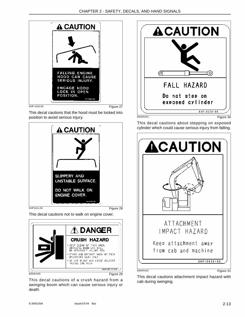
KHP-1010-00 Figure 27
This decal cautions that the hood must be locked into position to avoid serious injury.
KHP1011-00 Figure 28
This decal cautions not to walk on engine cover.
BS04H100 Figure 29
This decal cautions of a crush hazard from a swinging boom which can cause serious injury or death.
BS04H101 Figure 30
This decal cautions about stepping on exposed cylinder which could cause serious injury from falling.
BS04H102 Figure 31
This decal cautions attachment impact hazard with cab during swinging.
2-136-34551NA Issued 8-04 Bur
CHAPTER 2 - SAFETY, DECALS, AND HAND SIGNALS
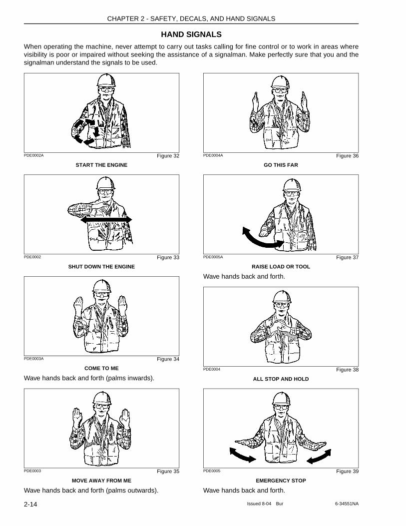
HAND SIGNALSWhen operating the machine, never attempt to carry out tasks calling for fine control or to work in areas where visibility is poor or impaired without seeking the assistance of a signalman. Make perfectly sure that you and the signalman understand the signals to be used.
PDE0002A Figure 32
START THE ENGINE
PDE0002 Figure 33
SHUT DOWN THE ENGINE
PDE0003A Figure 34
COME TO ME
Wave hands back and forth (palms inwards).
PDE0003 Figure 35
MOVE AWAY FROM ME
Wave hands back and forth (palms outwards).
PDE0004A Figure 36
GO THIS FAR
PDE0005A Figure 37
RAISE LOAD OR TOOL
Wave hands back and forth.
PDE0004 Figure 38
ALL STOP AND HOLD
PDE0005 Figure 39
EMERGENCY STOP
Wave hands back and forth.
2-14 Issued 8-04 Bur 6-34551NA
CHAPTER 2 - SAFETY, DECALS, AND HAND SIGNALS
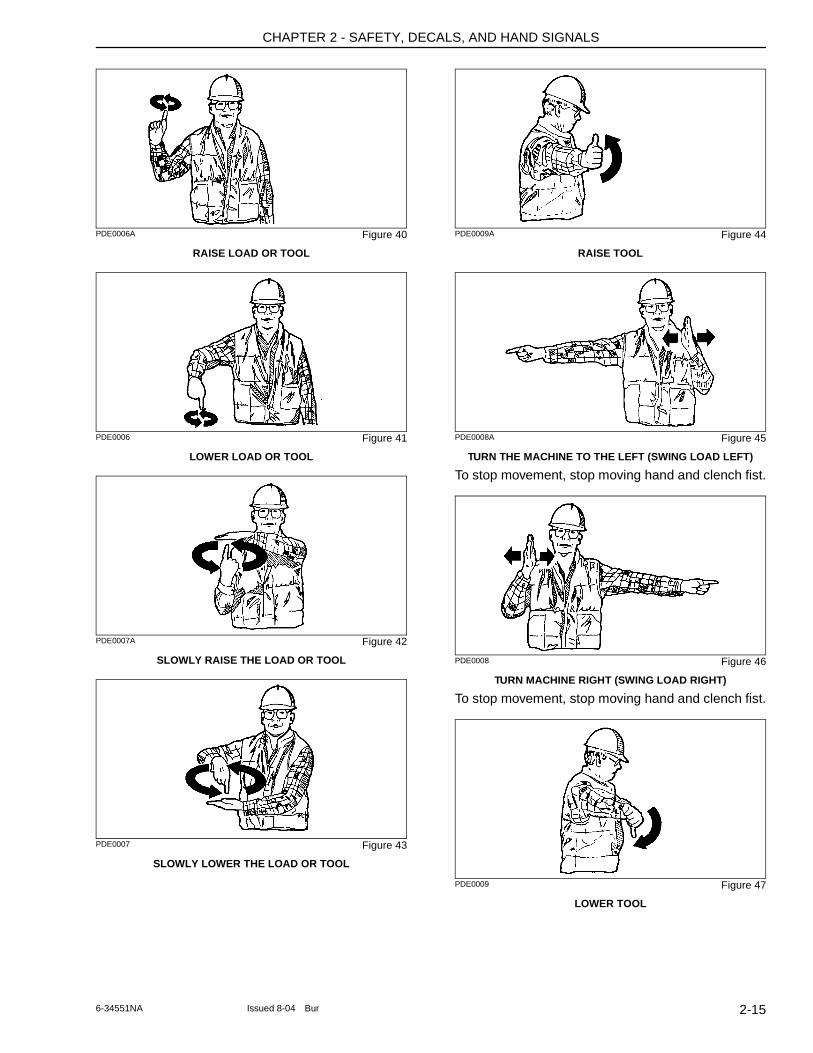
PDE0006A Figure 40
RAISE LOAD OR TOOL
PDE0006 Figure 41
LOWER LOAD OR TOOL
PDE0007A Figure 42
SLOWLY RAISE THE LOAD OR TOOL
PDE0007 Figure 43
SLOWLY LOWER THE LOAD OR TOOL
PDE0009A Figure 44
RAISE TOOL
PDE0008A Figure 45
TURN THE MACHINE TO THE LEFT (SWING LOAD LEFT)
To stop movement, stop moving hand and clench fist.
PDE0008 Figure 46
TURN MACHINE RIGHT (SWING LOAD RIGHT)
To stop movement, stop moving hand and clench fist.
PDE0009 Figure 47
LOWER TOOL
2-156-34551NA Issued 8-04 Bur
CHAPTER 2 - SAFETY, DECALS, AND HAND SIGNALS
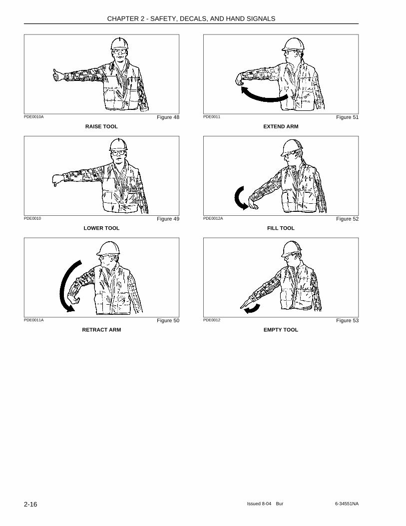
PDE0010A Figure 48
RAISE TOOL
PDE0010 Figure 49
LOWER TOOL
PDE0011A Figure 50
RETRACT ARM
PDE0011 Figure 51
EXTEND ARM
PDE0012A Figure 52
FILL TOOL
PDE0012 Figure 53
EMPTY TOOL
2-16 Issued 8-04 Bur 6-34551NA
CHAPTER 3 - INSTRUMENTS AND CONTROLS
Chapter 3
INSTRUMENTS AND CONTROLS
TABLE OF CONTENTS
CAB DOOR . . . . . . . . . . . . . . . . . . . . . . . . . . . . . . . . . . . . . . . . . . . . . . . . . . . . . . . . . . . . . . . . . . . . . . . . . . . . . 3-3
STEPS AND ACCESS HANDLES . . . . . . . . . . . . . . . . . . . . . . . . . . . . . . . . . . . . . . . . . . . . . . . . . . . . . . . . . . . . 3-4
POSITION OF THE OPERATOR’S COMPARTMENT CONTROLS AND ACCESSORIES . . . . . . . . . . . . . . . . 3-5
RIGHT-HAND CONTROL ARM . . . . . . . . . . . . . . . . . . . . . . . . . . . . . . . . . . . . . . . . . . . . . . . . . . . . . . . . . . . . . . 3-6
INSTRUMENT PANEL . . . . . . . . . . . . . . . . . . . . . . . . . . . . . . . . . . . . . . . . . . . . . . . . . . . . . . . . . . . . . . . . . . . . . 3-7
LEFT-HAND CONTROL ARM FOR CX75SR . . . . . . . . . . . . . . . . . . . . . . . . . . . . . . . . . . . . . . . . . . . . . . . . . . . 3-9
LEFT-HAND CONTROL ARM FOR CX135SR . . . . . . . . . . . . . . . . . . . . . . . . . . . . . . . . . . . . . . . . . . . . . . . . . 3-10
WORKING LIGHT SWITCH . . . . . . . . . . . . . . . . . . . . . . . . . . . . . . . . . . . . . . . . . . . . . . . . . . . . . . . . . . . . . . . . 3-11
WINDSHIELD WASHER SWITCH . . . . . . . . . . . . . . . . . . . . . . . . . . . . . . . . . . . . . . . . . . . . . . . . . . . . . . . . . . . 3-11
WINDSHIELD WIPER SWITCH . . . . . . . . . . . . . . . . . . . . . . . . . . . . . . . . . . . . . . . . . . . . . . . . . . . . . . . . . . . . . 3-11
HIGH SPEED TRAVEL SWITCH . . . . . . . . . . . . . . . . . . . . . . . . . . . . . . . . . . . . . . . . . . . . . . . . . . . . . . . . . . . . 3-11
HEATING, VENTILATION AND AIR-CONDITIONING CONTROL . . . . . . . . . . . . . . . . . . . . . . . . . . . . . . . . . . 3-12
FUNCTION CANCELLATION LEVER . . . . . . . . . . . . . . . . . . . . . . . . . . . . . . . . . . . . . . . . . . . . . . . . . . . . . . . . 3-13
ARM AND UPPERSTRUCTURE SWING LEFT-HAND CONTROL LEVER . . . . . . . . . . . . . . . . . . . . . . . . . . . 3-13
BOOM AND BUCKET RIGHT-HAND CONTROL LEVER . . . . . . . . . . . . . . . . . . . . . . . . . . . . . . . . . . . . . . . . . 3-14
TRAVEL CONTROL . . . . . . . . . . . . . . . . . . . . . . . . . . . . . . . . . . . . . . . . . . . . . . . . . . . . . . . . . . . . . . . . . . . . . . 3-15
OFFSET BOOM CONTROL PEDAL (IF EQUIPPED) . . . . . . . . . . . . . . . . . . . . . . . . . . . . . . . . . . . . . . . . . . . . 3-16
OPTION PEDAL . . . . . . . . . . . . . . . . . . . . . . . . . . . . . . . . . . . . . . . . . . . . . . . . . . . . . . . . . . . . . . . . . . . . . . . . . 3-16
UNLOCKING AND LOCKING OF PEDALS . . . . . . . . . . . . . . . . . . . . . . . . . . . . . . . . . . . . . . . . . . . . . . . . . . . . 3-16Unlocking . . . . . . . . . . . . . . . . . . . . . . . . . . . . . . . . . . . . . . . . . . . . . . . . . . . . . . . . . . . . . . . . . . . . . . . . . . . . 3-16Locking . . . . . . . . . . . . . . . . . . . . . . . . . . . . . . . . . . . . . . . . . . . . . . . . . . . . . . . . . . . . . . . . . . . . . . . . . . . . . . 3-16
DOZER BLADE CONTROL LEVER (IF EQUIPPED) . . . . . . . . . . . . . . . . . . . . . . . . . . . . . . . . . . . . . . . . . . . . . 3-17
CAB LIGHT . . . . . . . . . . . . . . . . . . . . . . . . . . . . . . . . . . . . . . . . . . . . . . . . . . . . . . . . . . . . . . . . . . . . . . . . . . . . . 3-17
COAT HANGER HOOK . . . . . . . . . . . . . . . . . . . . . . . . . . . . . . . . . . . . . . . . . . . . . . . . . . . . . . . . . . . . . . . . . . . 3-17
REAR RIGHT-HAND SIDE WINDOW . . . . . . . . . . . . . . . . . . . . . . . . . . . . . . . . . . . . . . . . . . . . . . . . . . . . . . . . 3-17
STORAGE COMPARTMENT . . . . . . . . . . . . . . . . . . . . . . . . . . . . . . . . . . . . . . . . . . . . . . . . . . . . . . . . . . . . . . . 3-18
STORAGE TRAY . . . . . . . . . . . . . . . . . . . . . . . . . . . . . . . . . . . . . . . . . . . . . . . . . . . . . . . . . . . . . . . . . . . . . . . . 3-18
ASHTRAY . . . . . . . . . . . . . . . . . . . . . . . . . . . . . . . . . . . . . . . . . . . . . . . . . . . . . . . . . . . . . . . . . . . . . . . . . . . . . . 3-18
CAB RADIO COMPARTMENT . . . . . . . . . . . . . . . . . . . . . . . . . . . . . . . . . . . . . . . . . . . . . . . . . . . . . . . . . . . . . . 3-18
SPEAKER COMPARTMENTS . . . . . . . . . . . . . . . . . . . . . . . . . . . . . . . . . . . . . . . . . . . . . . . . . . . . . . . . . . . . . . 3-18
FUSE BOX . . . . . . . . . . . . . . . . . . . . . . . . . . . . . . . . . . . . . . . . . . . . . . . . . . . . . . . . . . . . . . . . . . . . . . . . . . . . . 3-18
OPERATOR'S SEAT . . . . . . . . . . . . . . . . . . . . . . . . . . . . . . . . . . . . . . . . . . . . . . . . . . . . . . . . . . . . . . . . . . . . . 3-19
WINDSHIELD . . . . . . . . . . . . . . . . . . . . . . . . . . . . . . . . . . . . . . . . . . . . . . . . . . . . . . . . . . . . . . . . . . . . . . . . . . . 3-22Opening . . . . . . . . . . . . . . . . . . . . . . . . . . . . . . . . . . . . . . . . . . . . . . . . . . . . . . . . . . . . . . . . . . . . . . . . . . . . . 3-22Closing . . . . . . . . . . . . . . . . . . . . . . . . . . . . . . . . . . . . . . . . . . . . . . . . . . . . . . . . . . . . . . . . . . . . . . . . . . . . . . 3-22
LOWER FRONT WINDOW . . . . . . . . . . . . . . . . . . . . . . . . . . . . . . . . . . . . . . . . . . . . . . . . . . . . . . . . . . . . . . . . 3-23
WINDOW-BREAKER HAMMER . . . . . . . . . . . . . . . . . . . . . . . . . . . . . . . . . . . . . . . . . . . . . . . . . . . . . . . . . . . . 3-23
AIR VENTS . . . . . . . . . . . . . . . . . . . . . . . . . . . . . . . . . . . . . . . . . . . . . . . . . . . . . . . . . . . . . . . . . . . . . . . . . . . . . 3-23
REAR VIEW MIRRORS - CX75SR, CX80 . . . . . . . . . . . . . . . . . . . . . . . . . . . . . . . . . . . . . . . . . . . . . . . . . . . . . 3-24On the cab . . . . . . . . . . . . . . . . . . . . . . . . . . . . . . . . . . . . . . . . . . . . . . . . . . . . . . . . . . . . . . . . . . . . . . . . . . . 3-24
3-1Issued 8-04 Bur 6-34551NA
CHAPTER 3 - INSTRUMENTS AND CONTROLS
On the upperstructure . . . . . . . . . . . . . . . . . . . . . . . . . . . . . . . . . . . . . . . . . . . . . . . . . . . . . . . . . . . . . . . . . . .3-24Rear . . . . . . . . . . . . . . . . . . . . . . . . . . . . . . . . . . . . . . . . . . . . . . . . . . . . . . . . . . . . . . . . . . . . . . . . . . . . . . . .3-24
REAR VIEW MIRRORS CX135SR . . . . . . . . . . . . . . . . . . . . . . . . . . . . . . . . . . . . . . . . . . . . . . . . . . . . . . . . . . 3-24On the cab . . . . . . . . . . . . . . . . . . . . . . . . . . . . . . . . . . . . . . . . . . . . . . . . . . . . . . . . . . . . . . . . . . . . . . . . . . . .3-24On the upperstructure . . . . . . . . . . . . . . . . . . . . . . . . . . . . . . . . . . . . . . . . . . . . . . . . . . . . . . . . . . . . . . . . . . .3-25Rear . . . . . . . . . . . . . . . . . . . . . . . . . . . . . . . . . . . . . . . . . . . . . . . . . . . . . . . . . . . . . . . . . . . . . . . . . . . . . . . .3-25
FUEL TANK . . . . . . . . . . . . . . . . . . . . . . . . . . . . . . . . . . . . . . . . . . . . . . . . . . . . . . . . . . . . . . . . . . . . . . . . . . . . 3-25
UPPER HOOD - CX75SR, CX80 . . . . . . . . . . . . . . . . . . . . . . . . . . . . . . . . . . . . . . . . . . . . . . . . . . . . . . . . . . . 3-25
ENGINE HOOD . . . . . . . . . . . . . . . . . . . . . . . . . . . . . . . . . . . . . . . . . . . . . . . . . . . . . . . . . . . . . . . . . . . . . . . . . 3-26CX75SR, CX80 . . . . . . . . . . . . . . . . . . . . . . . . . . . . . . . . . . . . . . . . . . . . . . . . . . . . . . . . . . . . . . . . . . . . . . . .3-26CX135SR . . . . . . . . . . . . . . . . . . . . . . . . . . . . . . . . . . . . . . . . . . . . . . . . . . . . . . . . . . . . . . . . . . . . . . . . . . . .3-26
SIDE DOORS . . . . . . . . . . . . . . . . . . . . . . . . . . . . . . . . . . . . . . . . . . . . . . . . . . . . . . . . . . . . . . . . . . . . . . . . . . 3-27Left-hand rear side door . . . . . . . . . . . . . . . . . . . . . . . . . . . . . . . . . . . . . . . . . . . . . . . . . . . . . . . . . . . . . . . . .3-27Right-hand rear side door . . . . . . . . . . . . . . . . . . . . . . . . . . . . . . . . . . . . . . . . . . . . . . . . . . . . . . . . . . . . . . . .3-27Right-hand front side door . . . . . . . . . . . . . . . . . . . . . . . . . . . . . . . . . . . . . . . . . . . . . . . . . . . . . . . . . . . . . . . .3-27
ROTATING BEACON CABLE (OPTION) . . . . . . . . . . . . . . . . . . . . . . . . . . . . . . . . . . . . . . . . . . . . . . . . . . . . . 3-28
TOWING POINT . . . . . . . . . . . . . . . . . . . . . . . . . . . . . . . . . . . . . . . . . . . . . . . . . . . . . . . . . . . . . . . . . . . . . . . . 3-28
LOAD HANDLING EYES . . . . . . . . . . . . . . . . . . . . . . . . . . . . . . . . . . . . . . . . . . . . . . . . . . . . . . . . . . . . . . . . . . 3-29
WINDSHIELD WASHER RESERVOIR . . . . . . . . . . . . . . . . . . . . . . . . . . . . . . . . . . . . . . . . . . . . . . . . . . . . . . . 3-29
TOOL SUPPLY VALVES (OPTIONAL) . . . . . . . . . . . . . . . . . . . . . . . . . . . . . . . . . . . . . . . . . . . . . . . . . . . . . . . 3-29
TOOL FLOW SELECTOR VALVE (OPTIONAL) . . . . . . . . . . . . . . . . . . . . . . . . . . . . . . . . . . . . . . . . . . . . . . . . 3-30
3-2 Issued 8-04 Bur 6-34551NA
CHAPTER 3 - INSTRUMENTS AND CONTROLS
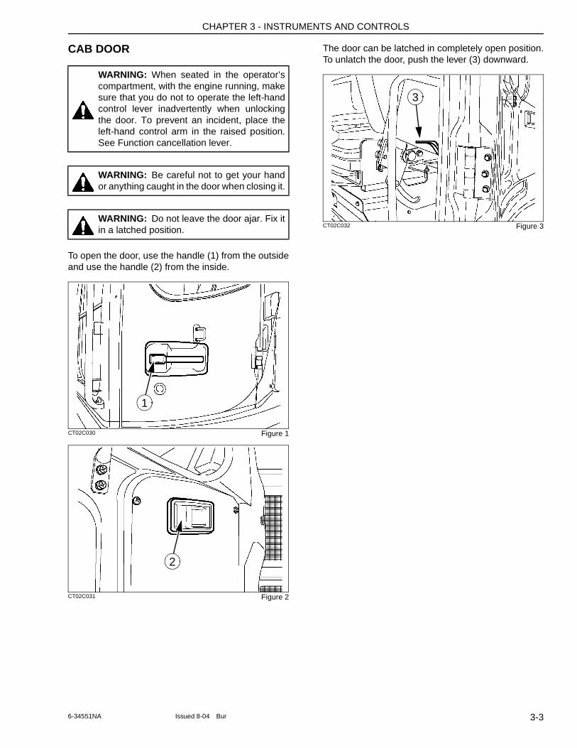
CAB DOOR
To open the door, use the handle (1) from the outside and use the handle (2) from the inside.
CT02C030 Figure 1
CT02C031 Figure 2
The door can be latched in completely open position. To unlatch the door, push the lever (3) downward.
CT02C032 Figure 3
WARNING: When seated in the operator’s compartment, with the engine running, make sure that you do not to operate the left-hand control lever inadvertently when unlocking the door. To prevent an incident, place the left-hand control arm in the raised position. See Function cancellation lever.
WARNING: Be careful not to get your hand or anything caught in the door when closing it.
WARNING: Do not leave the door ajar. Fix it in a latched position.
1
2
3
3-36-34551NA Issued 8-04 Bur
CHAPTER 3 - INSTRUMENTS AND CONTROLS
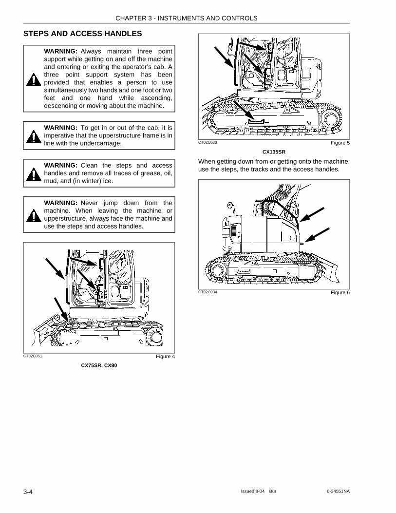
STEPS AND ACCESS HANDLES
CT02C051 Figure 4
CX75SR, CX80
CT02C033 Figure 5
CX135SR
When getting down from or getting onto the machine, use the steps, the tracks and the access handles.
CT02C034 Figure 6
WARNING: Always maintain three point support while getting on and off the machine and entering or exiting the operator’s cab. A three point support system has been provided that enables a person to use simultaneously two hands and one foot or two feet and one hand while ascending, descending or moving about the machine.
WARNING: To get in or out of the cab, it is imperative that the upperstructure frame is in line with the undercarriage.
WARNING: Clean the steps and access handles and remove all traces of grease, oil, mud, and (in winter) ice.
WARNING: Never jump down from the machine. When leaving the machine or upperstructure, always face the machine and use the steps and access handles.
3-4 Issued 8-04 Bur 6-34551NA
CHAPTER 3 - INSTRUMENTS AND CONTROLS
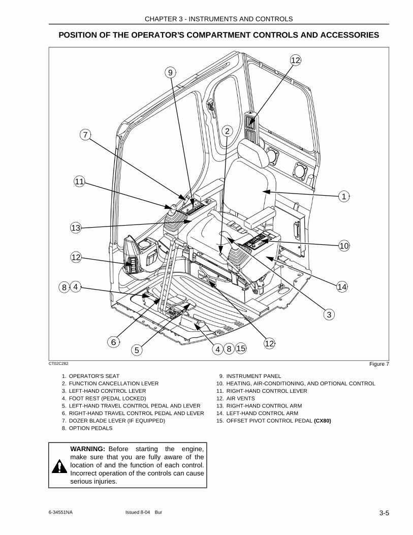
POSITION OF THE OPERATOR’S COMPARTMENT CONTROLS AND ACCESSORIES
CT02C282 Figure 7
1. OPERATOR'S SEAT 9. INSTRUMENT PANEL2. FUNCTION CANCELLATION LEVER 10. HEATING, AIR-CONDITIONING, AND OPTIONAL CONTROL3. LEFT-HAND CONTROL LEVER 11. RIGHT-HAND CONTROL LEVER4. FOOT REST (PEDAL LOCKED) 12. AIR VENTS5. LEFT-HAND TRAVEL CONTROL PEDAL AND LEVER 13. RIGHT-HAND CONTROL ARM6. RIGHT-HAND TRAVEL CONTROL PEDAL AND LEVER 14. LEFT-HAND CONTROL ARM7. DOZER BLADE LEVER (IF EQUIPPED) 15. OFFSET PIVOT CONTROL PEDAL (CX80)8. OPTION PEDALS
1
8
8
2
3
4
456
9
11
12
12
14
13
12
10
7
15
WARNING: Before starting the engine, make sure that you are fully aware of the location of and the function of each control. Incorrect operation of the controls can cause serious injuries.
3-56-34551NA Issued 8-04 Bur
CHAPTER 3 - INSTRUMENTS AND CONTROLS
RIGHT-HAND CONTROL ARM
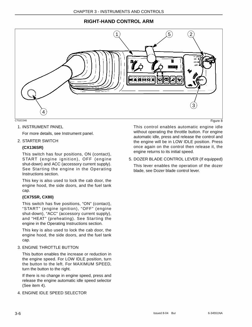
CT02C046 Figure 8
1. INSTRUMENT PANEL
For more details, see Instrument panel.
2. STARTER SWITCH
(CX136SR)
This switch has four positions, ON (contact), START (eng ine ign i t i on ) , OFF (eng ine shut-down) and ACC (accessory current supply). See Star ting the engine in the Operating Instructions section.
This key is also used to lock the cab door, the engine hood, the side doors, and the fuel tank cap.
(CX75SR, CX80)
This switch has five positions, “ON” (contact), “START” (engine ignit ion), “OFF” (engine shut-down), “ACC” (accessory current supply), and “HEAT” (preheating). See Star ting the engine in the Operating Instructions section.
This key is also used to lock the cab door, the engine hood, the side doors, and the fuel tank cap.
3. ENGINE THROTTLE BUTTON
This button enables the increase or reduction in the engine speed. For LOW IDLE position, turn the button to the left. For MAXIMUM SPEED, turn the button to the right.
If there is no change in engine speed, press and release the engine automatic idle speed selector (See item 4).
4. ENGINE IDLE SPEED SELECTOR
This control enables automatic engine idle without operating the throttle button. For engine automatic idle, press and release the control and the engine will be in LOW IDLE position. Press once again on the control then release it, the engine returns to its initial speed.
5. DOZER BLADE CONTROL LEVER (If equipped)
This lever enables the operation of the dozer blade, see Dozer blade control lever.
2
43
1 5
3-6 Issued 8-04 Bur 6-34551NA
CHAPTER 3 - INSTRUMENTS AND CONTROLS
INSTRUMENT PANEL
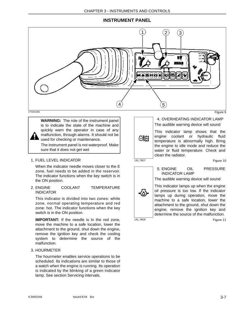
CT02C046 Figure 9
1. FUEL LEVEL INDICATOR
When the indicator needle moves closer to the E zone, fuel needs to be added in the reservoir. The indicator functions when the key switch is in the ON position.
2. ENGINE COOLANT TEMPERATURE INDICATOR
This indicator is divided into two zones: white zone, normal operating temperature and red zone: hot. The indicator functions when the key switch is in the ON position.
IMPORTANT: If the needle is in the red zone, move the machine to a safe location, lower the attachment to the ground, shut down the engine, remove the ignition key and check the cooling system to determine the source of the malfunction.
3. HOURMETER
The hourmeter enables service operations to be scheduled. Its indications are similar to those of a watch when the engine is running. Its operation is indicated by the blinking of a green indicator lamp. See section Servicing intervals.
135_TBD7 Figure 10
135_TBD8 Figure 11
2 31
4 5
WARNING: The role of the instrument panel is to indicate the state of the machine and quickly warn the operator in case of any malfunction, through alarms. It should not be used for checking or maintenance.The instrument panel is not waterproof. Make sure that it does not get wet
4. OVERHEATING INDICATOR LAMPThe audible warning device will sound
This indicator lamp shows that the engine coolant or hydraulic fluid temperature is abnormally high. Bring the engine to idle mode and reduce the water or fluid temperature. Check and clean the radiator.
5. ENGINE OIL PRESSURE INDICATOR LAMP
The audible warning device will sound
This indicator lamps up when the engine oil pressure is too low. If the indicator lamps up during operation, move the machine to a safe location, lower the attachment to the ground, shut down the engine, remove the ignition key and determine the source of the malfunction.
3-76-34551NA Issued 8-04 Bur
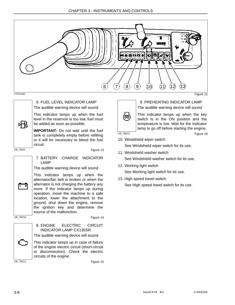
CHAPTER 3 - INSTRUMENTS AND CONTROLS
CT02C046 Figure 12
135_TBD9 Figure 13
135_TBD10 Figure 14
135_TBD11 Figure 15
135_TBD12 Figure 16
10. Windshield wiper switch
See Windshield wiper switch for its use.
11. Windshield washer switch
See Windshield washer switch for its use.
12. Working light switch
See Working light switch for its use.
13. High speed travel switch.
See High speed travel switch for its use.
9 10 117 8 12 136
6. FUEL LEVEL INDICATOR LAMPThe audible warning device will sound
This indicator lamps up when the fuel level in the reservoir is too low, fuel must be added as soon as possible.
IMPORTANT: Do not wait until the fuel tank is completely empty before refilling or it will be necessary to bleed the fuel circuit.
7. BATTERY CHARGE INDICATOR LAMP
The audible warning device will sound
This indicator lamps up when the alternator/fan belt is broken or when the alternator is not charging the battery any more. If the indicator lamps up during operation, move the machine to a safe location, lower the attachment to the ground, shut down the engine, remove the ignition key and determine the source of the malfunction.
8. ENGINE ELECTRIC CIRCUIT INDICATOR LAMP CX135SR
The audible warning device will sound
This indicator lamps up in case of failure of the engine electric circuit (short-circuit or disconnection). Check the electric circuits of the engine.
9. PREHEATING INDICATOR LAMPThe audible warning device will sound
This indicator lamps up when the key switch is in the ON position and the temperature is low. Wait for the indicator lamp to go off before starting the engine.
3-8 Issued 8-04 Bur 6-34551NA
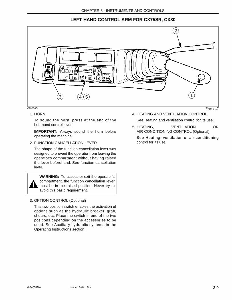
CHAPTER 3 - INSTRUMENTS AND CONTROLS
LEFT-HAND CONTROL ARM FOR CX75SR, CX80
CT02C064 Figure 17
1. HORN
To sound the horn, press at the end of the Left-hand control lever.
IMPORTANT: Always sound the horn before operating the machine.
2. FUNCTION CANCELLATION LEVER
The shape of the function cancellation lever was designed to prevent the operator from leaving the operator’s compartment without having raised the lever beforehand. See function cancellation lever.
3. OPTION CONTROL (Optional)
This two-position switch enables the activation of options such as the hydraulic breaker, grab, shears, etc. Place the switch in one of the two positions depending on the accessories to be used. See Auxiliary hydraulic systems in the Operating Instructions section.
4. HEATING AND VENTILATION CONTROL
See Heating and ventilation control for its use.
5. HEATING, VENTILATION OR AIR-CONDITIONING CONTROL (Optional)
See Heating, ventilation or air-conditioning control for its use.
2
13 4 5
WARNING: To access or exit the operator’s compartment, the function cancellation lever must be in the raised position. Never try to avoid this basic requirement.
3-96-34551NA Issued 8-04 Bur
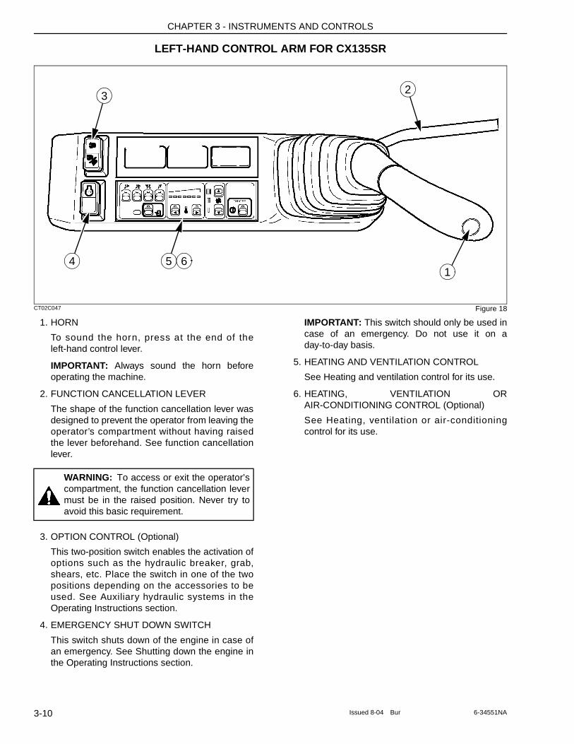
CHAPTER 3 - INSTRUMENTS AND CONTROLS
LEFT-HAND CONTROL ARM FOR CX135SR
CT02C047 Figure 18
1. HORN
To sound the horn, press at the end of the left-hand control lever.
IMPORTANT: Always sound the horn before operating the machine.
2. FUNCTION CANCELLATION LEVER
The shape of the function cancellation lever was designed to prevent the operator from leaving the operator’s compartment without having raised the lever beforehand. See function cancellation lever.
3. OPTION CONTROL (Optional)
This two-position switch enables the activation of options such as the hydraulic breaker, grab, shears, etc. Place the switch in one of the two positions depending on the accessories to be used. See Auxiliary hydraulic systems in the Operating Instructions section.
4. EMERGENCY SHUT DOWN SWITCH
This switch shuts down of the engine in case of an emergency. See Shutting down the engine in the Operating Instructions section.
IMPORTANT: This switch should only be used in case of an emergency. Do not use it on a day-to-day basis.
5. HEATING AND VENTILATION CONTROL
See Heating and ventilation control for its use.
6. HEATING, VENTILATION OR AIR-CONDITIONING CONTROL (Optional)
See Heating, ventilation or air-conditioning control for its use.
2
1
3
4 5 6
WARNING: To access or exit the operator’s compartment, the function cancellation lever must be in the raised position. Never try to avoid this basic requirement.
3-10 Issued 8-04 Bur 6-34551NA
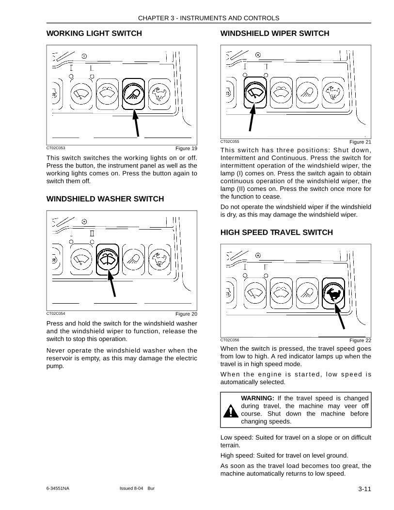
CHAPTER 3 - INSTRUMENTS AND CONTROLS
WORKING LIGHT SWITCH
CT02C053 Figure 19
This switch switches the working lights on or off. Press the button, the instrument panel as well as the working lights comes on. Press the button again to switch them off.
WINDSHIELD WASHER SWITCH
CT02C054 Figure 20
Press and hold the switch for the windshield washer and the windshield wiper to function, release the switch to stop this operation.
Never operate the windshield washer when the reservoir is empty, as this may damage the electric pump.
WINDSHIELD WIPER SWITCH
CT02C055 Figure 21
This swi tch has three posi t ions: Shut down, Intermittent and Continuous. Press the switch for intermittent operation of the windshield wiper, the lamp (I) comes on. Press the switch again to obtain continuous operation of the windshield wiper, the lamp (II) comes on. Press the switch once more for the function to cease.
Do not operate the windshield wiper if the windshield is dry, as this may damage the windshield wiper.
HIGH SPEED TRAVEL SWITCH
CT02C056 Figure 22
When the switch is pressed, the travel speed goes from low to high. A red indicator lamps up when the travel is in high speed mode.
When the eng ine i s s ta r ted , l ow speed i s automatically selected.
Low speed: Suited for travel on a slope or on difficult terrain.
High speed: Suited for travel on level ground.
As soon as the travel load becomes too great, the machine automatically returns to low speed.
WARNING: If the travel speed is changed during travel, the machine may veer off course. Shut down the machine before changing speeds.
3-116-34551NA Issued 8-04 Bur
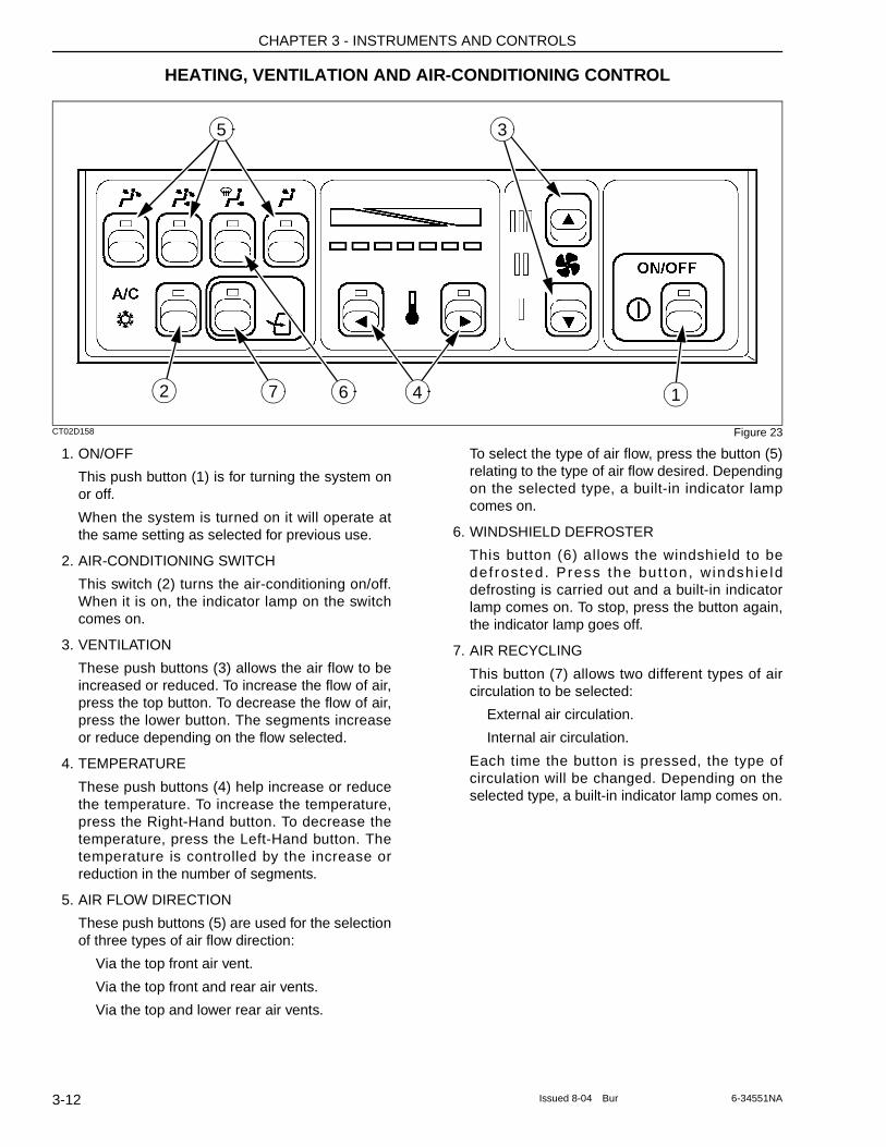
CHAPTER 3 - INSTRUMENTS AND CONTROLS
HEATING, VENTILATION AND AIR-CONDITIONING CONTROL
CT02D158 Figure 23
1. ON/OFF
This push button (1) is for turning the system on or off.
When the system is turned on it will operate at the same setting as selected for previous use.
2. AIR-CONDITIONING SWITCH
This switch (2) turns the air-conditioning on/off. When it is on, the indicator lamp on the switch comes on.
3. VENTILATION
These push buttons (3) allows the air flow to be increased or reduced. To increase the flow of air, press the top button. To decrease the flow of air, press the lower button. The segments increase or reduce depending on the flow selected.
4. TEMPERATURE
These push buttons (4) help increase or reduce the temperature. To increase the temperature, press the Right-Hand button. To decrease the temperature, press the Left-Hand button. The temperature is controlled by the increase or reduction in the number of segments.
5. AIR FLOW DIRECTION
These push buttons (5) are used for the selection of three types of air flow direction:
Via the top front air vent.
Via the top front and rear air vents.
Via the top and lower rear air vents.
To select the type of air flow, press the button (5) relating to the type of air flow desired. Depending on the selected type, a built-in indicator lamp comes on.
6. WINDSHIELD DEFROSTER
This button (6) allows the windshield to be def ros ted. Press the but ton , windsh ie ld defrosting is carried out and a built-in indicator lamp comes on. To stop, press the button again, the indicator lamp goes off.
7. AIR RECYCLING
This button (7) allows two different types of air circulation to be selected:
External air circulation.
Internal air circulation.
Each time the button is pressed, the type of circulation will be changed. Depending on the selected type, a built-in indicator lamp comes on.
1
3
4
5
2 7 6
3-12 Issued 8-04 Bur 6-34551NA
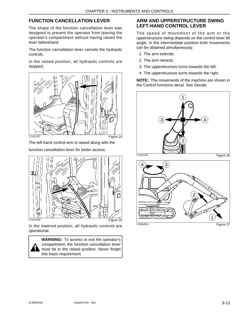
CHAPTER 3 - INSTRUMENTS AND CONTROLS
FUNCTION CANCELLATION LEVERThe shape of the function cancellation lever was designed to prevent the operator from leaving the operator’s compartment without having raised the lever beforehand.
The function cancellation lever cancels the hydraulic controls.
In the raised position, all hydraulic controls are stopped.
CT02C037 Figure 24
The left-hand control arm is raised along with the
function cancellation lever for better access.
CT02C038 Figure 25
In the lowered position, all hydraulic controls are operational.
ARM AND UPPERSTRUCTURE SWING LEFT-HAND CONTROL LEVERThe speed o f movemen t o f t he a r m o r t he upperstructure swing depends on the control lever tilt angle. In the intermediate position both movements can be obtained simultaneously.
1. The arm extends.
2. The arm retracts.
3. The upperstructure turns towards the left.
4. The upperstructure turns towards the right.
NOTE: The movements of the machine are shown in the Control functions decal. See Decals.
CT02C039 Figure 26
CS98M554 Figure 27
WARNING: To access or exit the operator’s compartment, the function cancellation lever must be in the raised position. Never forget this basic requirement.
1
2
3 4
3
2
4
1
3-136-34551NA Issued 8-04 Bur
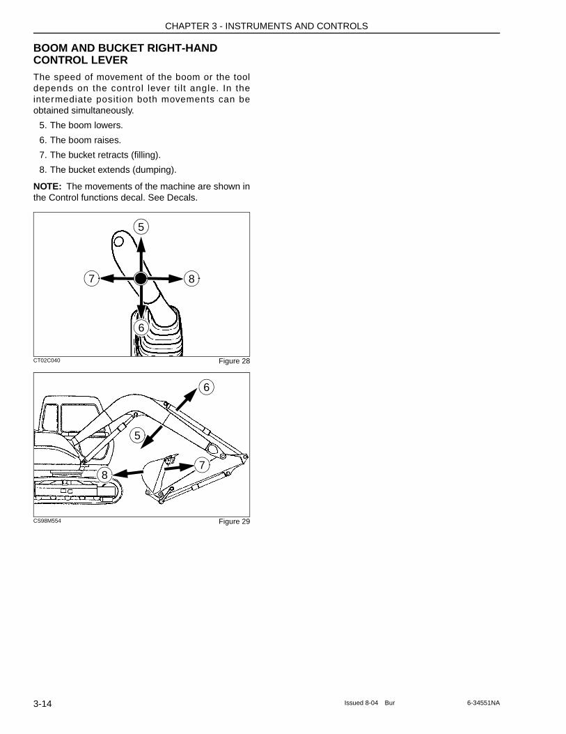
CHAPTER 3 - INSTRUMENTS AND CONTROLS
BOOM AND BUCKET RIGHT-HAND CONTROL LEVERThe speed of movement of the boom or the tool depends on the control lever t i l t angle. In the intermediate posit ion both movements can be obtained simultaneously.
5. The boom lowers.
6. The boom raises.
7. The bucket retracts (filling).
8. The bucket extends (dumping).
NOTE: The movements of the machine are shown in the Control functions decal. See Decals.
CT02C040 Figure 28
CS98M554 Figure 29
5
6
7 8
5
7
6
8
3-14 Issued 8-04 Bur 6-34551NA
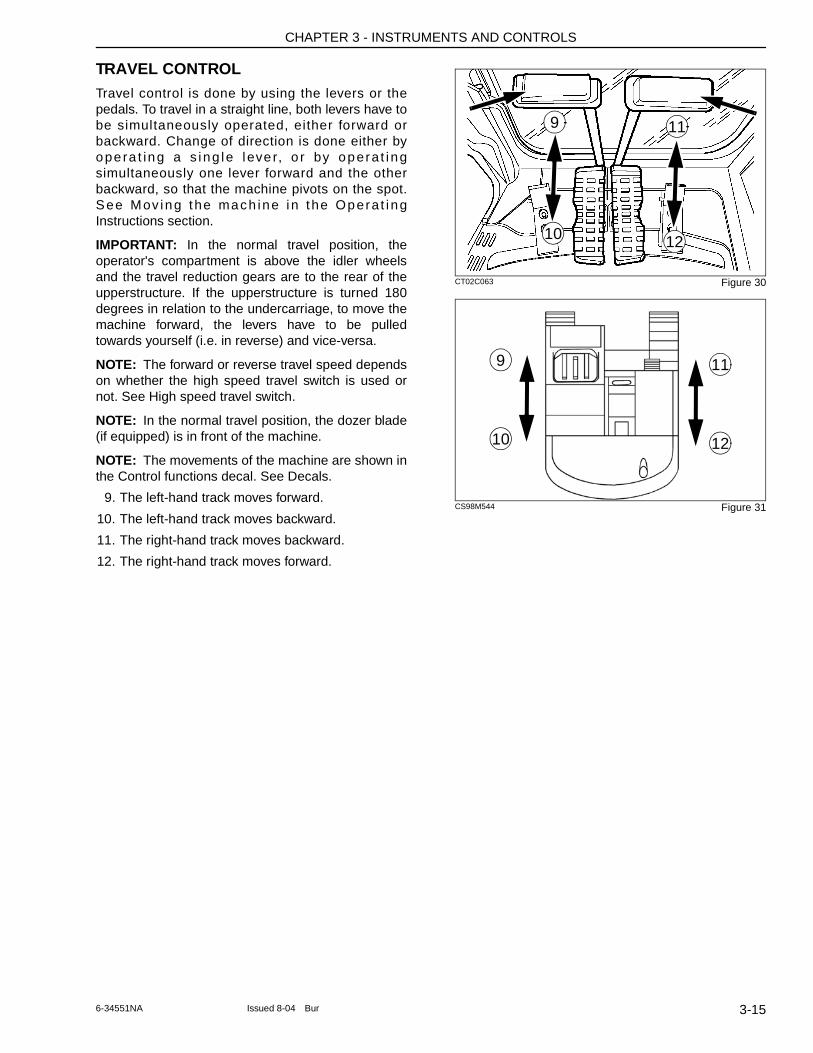
CHAPTER 3 - INSTRUMENTS AND CONTROLS
TRAVEL CONTROLTravel control is done by using the levers or the pedals. To travel in a straight line, both levers have to be simultaneously operated, either forward or backward. Change of direction is done either by ope ra t ing a s ing le l eve r, o r by opera t i ng simultaneously one lever forward and the other backward, so that the machine pivots on the spot. See Mov ing the mach ine i n the Opera t i ng Instructions section.
IMPORTANT: In the normal travel position, the operator's compartment is above the idler wheels and the travel reduction gears are to the rear of the upperstructure. If the upperstructure is turned 180 degrees in relation to the undercarriage, to move the machine forward, the levers have to be pulled towards yourself (i.e. in reverse) and vice-versa.
NOTE: The forward or reverse travel speed depends on whether the high speed travel switch is used or not. See High speed travel switch.
NOTE: In the normal travel position, the dozer blade (if equipped) is in front of the machine.
NOTE: The movements of the machine are shown in the Control functions decal. See Decals.
9. The left-hand track moves forward.
10. The left-hand track moves backward.
11. The right-hand track moves backward.
12. The right-hand track moves forward.
CT02C063 Figure 30
CS98M544 Figure 31
9 11
10 12
11
10 12
9
3-156-34551NA Issued 8-04 Bur
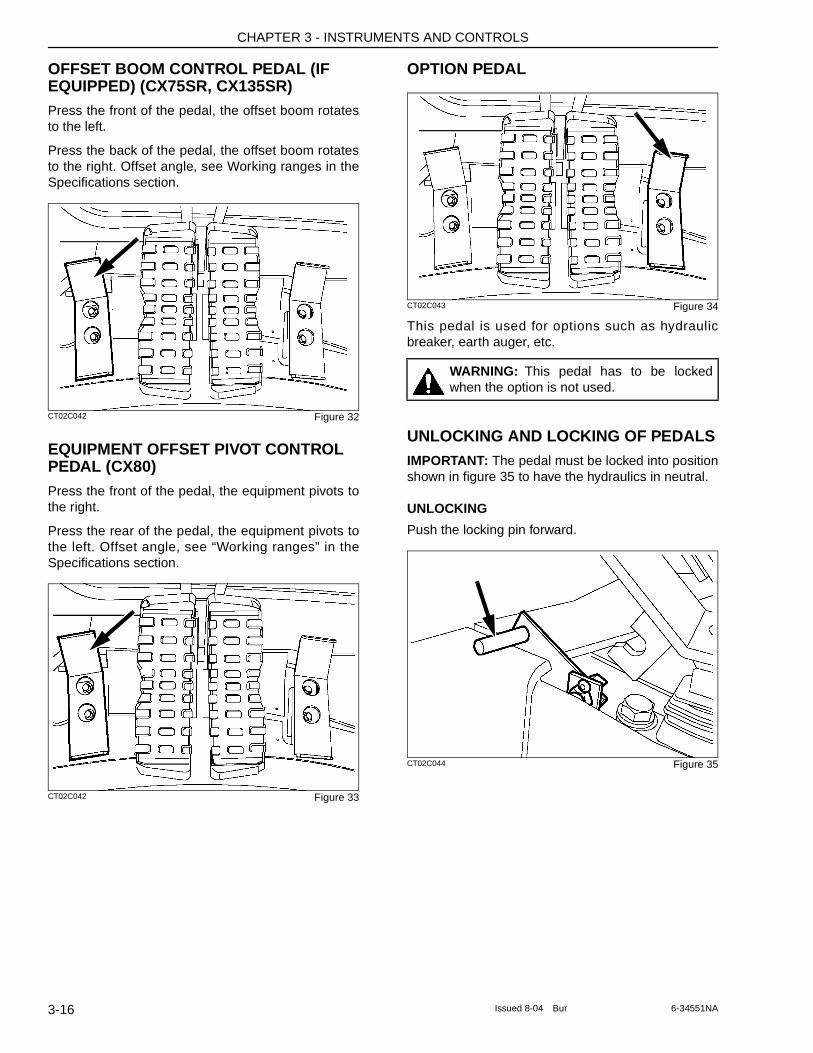
CHAPTER 3 - INSTRUMENTS AND CONTROLS
OFFSET BOOM CONTROL PEDAL (IF EQUIPPED) (CX75SR, CX135SR)Press the front of the pedal, the offset boom rotates to the left.
Press the back of the pedal, the offset boom rotates to the right. Offset angle, see Working ranges in the Specifications section.
CT02C042 Figure 32
EQUIPMENT OFFSET PIVOT CONTROL PEDAL (CX80)Press the front of the pedal, the equipment pivots to the right.
Press the rear of the pedal, the equipment pivots to the left. Offset angle, see “Working ranges” in the Specifications section.
CT02C042 Figure 33
OPTION PEDAL
CT02C043 Figure 34
This pedal is used for options such as hydraulic breaker, earth auger, etc.
UNLOCKING AND LOCKING OF PEDALSIMPORTANT: The pedal must be locked into position shown in figure 35 to have the hydraulics in neutral.
UNLOCKING
Push the locking pin forward.
CT02C044 Figure 35
WARNING: This pedal has to be locked when the option is not used.
3-16 Issued 8-04 Bur 6-34551NA
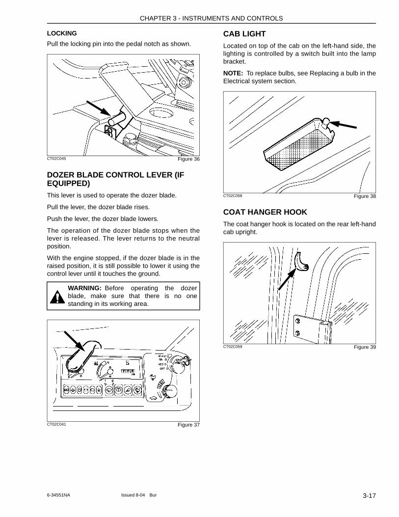
CHAPTER 3 - INSTRUMENTS AND CONTROLS
LOCKING
Pull the locking pin into the pedal notch as shown.
CT02C045 Figure 36
DOZER BLADE CONTROL LEVER (IF EQUIPPED)This lever is used to operate the dozer blade.
Pull the lever, the dozer blade rises.
Push the lever, the dozer blade lowers.
The operation of the dozer blade stops when the lever is released. The lever returns to the neutral position.
With the engine stopped, if the dozer blade is in the raised position, it is still possible to lower it using the control lever until it touches the ground.
CT02C041 Figure 37
CAB LIGHTLocated on top of the cab on the left-hand side, the lighting is controlled by a switch built into the lamp bracket.
NOTE: To replace bulbs, see Replacing a bulb in the Electrical system section.
CT02C058 Figure 38
COAT HANGER HOOKThe coat hanger hook is located on the rear left-hand cab upright.
CT02C059 Figure 39
WARNING: Before operating the dozer blade, make sure that there is no one standing in its working area.
3-176-34551NA Issued 8-04 Bur
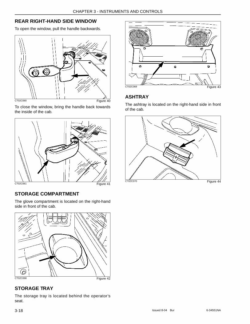
CHAPTER 3 - INSTRUMENTS AND CONTROLS
REAR RIGHT-HAND SIDE WINDOWTo open the window, pull the handle backwards.
CT02C060 Figure 40
To close the window, bring the handle back towards the inside of the cab.
CT02C061 Figure 41
STORAGE COMPARTMENTThe glove compartment is located on the right-hand side in front of the cab.
CT02C068 Figure 42
STORAGE TRAYThe storage tray is located behind the operator’s seat.
CT02C069 Figure 43
ASHTRAYThe ashtray is located on the right-hand side in front of the cab.
CT02C070 Figure 44
3-18 Issued 8-04 Bur 6-34551NA
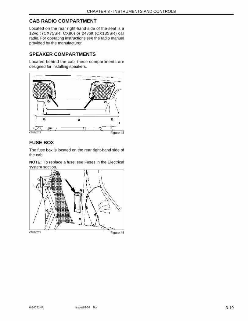
CHAPTER 3 - INSTRUMENTS AND CONTROLS
CAB RADIO COMPARTMENTLocated on the rear right-hand side of the seat is a 12volt (CX75SR, CX80) or 24volt (CX135SR) car radio. For operating instructions see the radio manual provided by the manufacturer.
SPEAKER COMPARTMENTSLocated behind the cab, these compartments are designed for installing speakers.
CT02C073 Figure 45
FUSE BOXThe fuse box is located on the rear right-hand side of the cab.
NOTE: To replace a fuse, see Fuses in the Electrical system section.
CT02C074 Figure 46
3-196-34551NA Issued 8-04 Bur
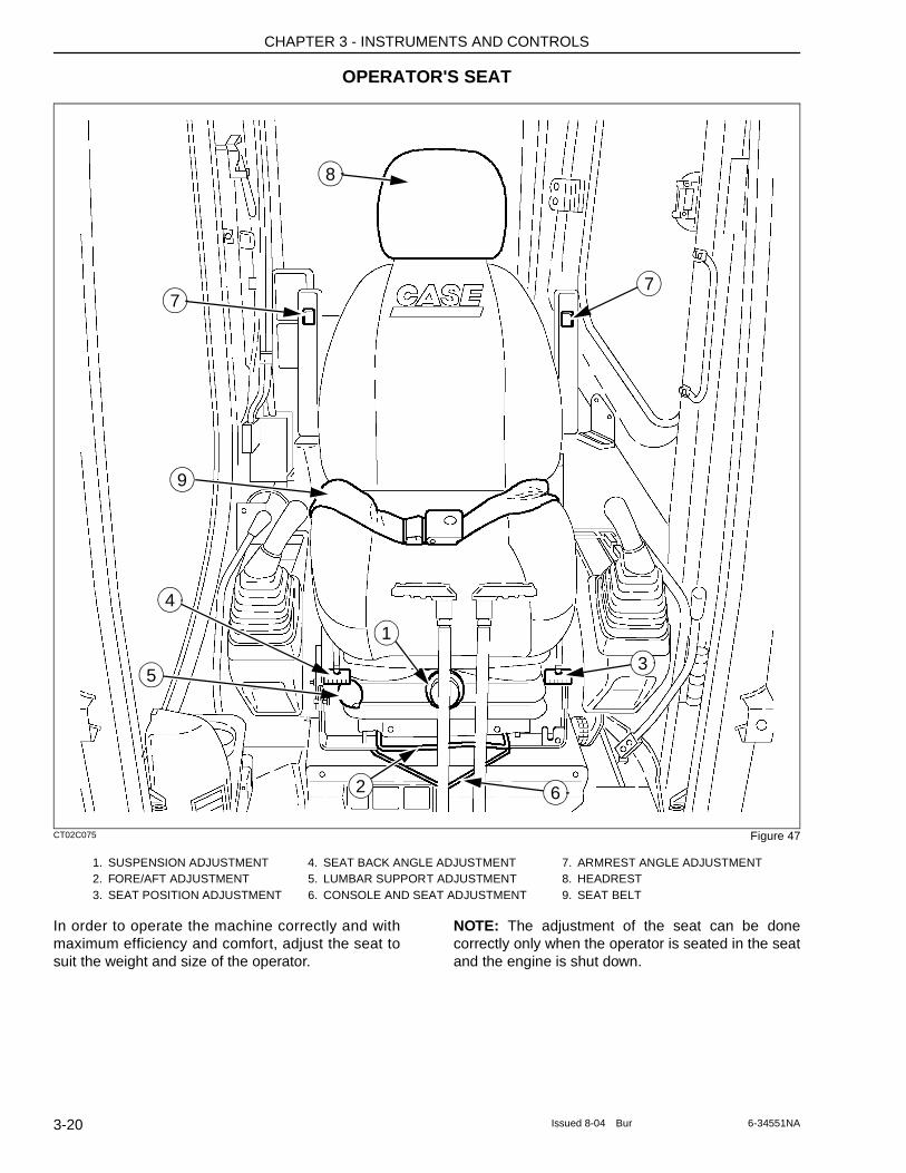
CHAPTER 3 - INSTRUMENTS AND CONTROLS
OPERATOR'S SEAT
CT02C075 Figure 47
In order to operate the machine correctly and with maximum efficiency and comfort, adjust the seat to suit the weight and size of the operator.
NOTE: The adjustment of the seat can be done correctly only when the operator is seated in the seat and the engine is shut down.
1. SUSPENSION ADJUSTMENT 4. SEAT BACK ANGLE ADJUSTMENT 7. ARMREST ANGLE ADJUSTMENT2. FORE/AFT ADJUSTMENT 5. LUMBAR SUPPORT ADJUSTMENT 8. HEADREST3. SEAT POSITION ADJUSTMENT 6. CONSOLE AND SEAT ADJUSTMENT 9. SEAT BELT
8
77
9
5
4
1
3
62
3-20 Issued 8-04 Bur 6-34551NA
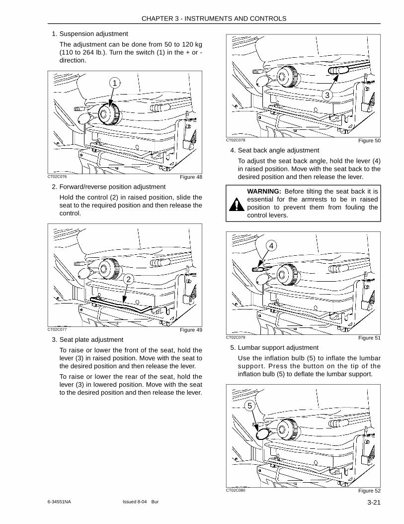
CHAPTER 3 - INSTRUMENTS AND CONTROLS
1. Suspension adjustment
The adjustment can be done from 50 to 120 kg (110 to 264 lb.). Turn the switch (1) in the + or - direction.
CT02C076 Figure 48
2. Forward/reverse position adjustment
Hold the control (2) in raised position, slide the seat to the required position and then release the control.
CT02C077 Figure 49
3. Seat plate adjustment
To raise or lower the front of the seat, hold the lever (3) in raised position. Move with the seat to the desired position and then release the lever.
To raise or lower the rear of the seat, hold the lever (3) in lowered position. Move with the seat to the desired position and then release the lever.
CT02C078 Figure 50
4. Seat back angle adjustment
To adjust the seat back angle, hold the lever (4) in raised position. Move with the seat back to the desired position and then release the lever.
CT02C079 Figure 51
5. Lumbar support adjustment
Use the inflation bulb (5) to inflate the lumbar suppor t. Press the button on the tip of the inflation bulb (5) to deflate the lumbar support.
CT02C080 Figure 52
1
2
WARNING: Before tilting the seat back it is essential for the armrests to be in raised position to prevent them from fouling the control levers.
3
4
5
3-216-34551NA Issued 8-04 Bur
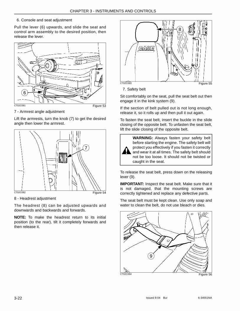
CHAPTER 3 - INSTRUMENTS AND CONTROLS
6. Console and seat adjustment
Pull the lever (6) upwards, and slide the seat and control arm assembly to the desired position, then release the lever.
CT02C081 Figure 53
7 - Armrest angle adjustment
Lift the armrests, turn the knob (7) to get the desired angle then lower the armrest.
CT02C082 Figure 54
8 - Headrest adjustment
The headrest (8) can be adjusted upwards and downwards and backwards and forwards.
NOTE: To make the headrest return to its initial position (to the rear), tilt it completely forwards and then release it.
CT02C083 Figure 55
7. Safety belt
Sit comfortably on the seat, pull the seat belt out then engage it in the kink system (9).
If the section of belt pulled out is not long enough, release it, so it rolls up and then pull it out again.
To fasten the seat belt, insert the buckle in the slide closing of the opposite belt. To unfasten the seat belt, lift the slide closing of the opposite belt.
To release the seat belt, press down on the releasing lever (9).
IMPORTANT: Inspect the seat belt. Make sure that it is not damaged, that the mounting screws are correctly tightened and replace any defective parts.
The seat belt must be kept clean. Use only soap and water to clean the belt, do not use bleach or dies.
CT02C084 Figure 56
6
7
WARNING: Always fasten your safety belt before starting the engine. The safety belt will protect you effectively if you fasten it correctly and wear it at all times. The safety belt should not be too loose. It should not be twisted or caught in the seat.
8
9
3-22 Issued 8-04 Bur 6-34551NA
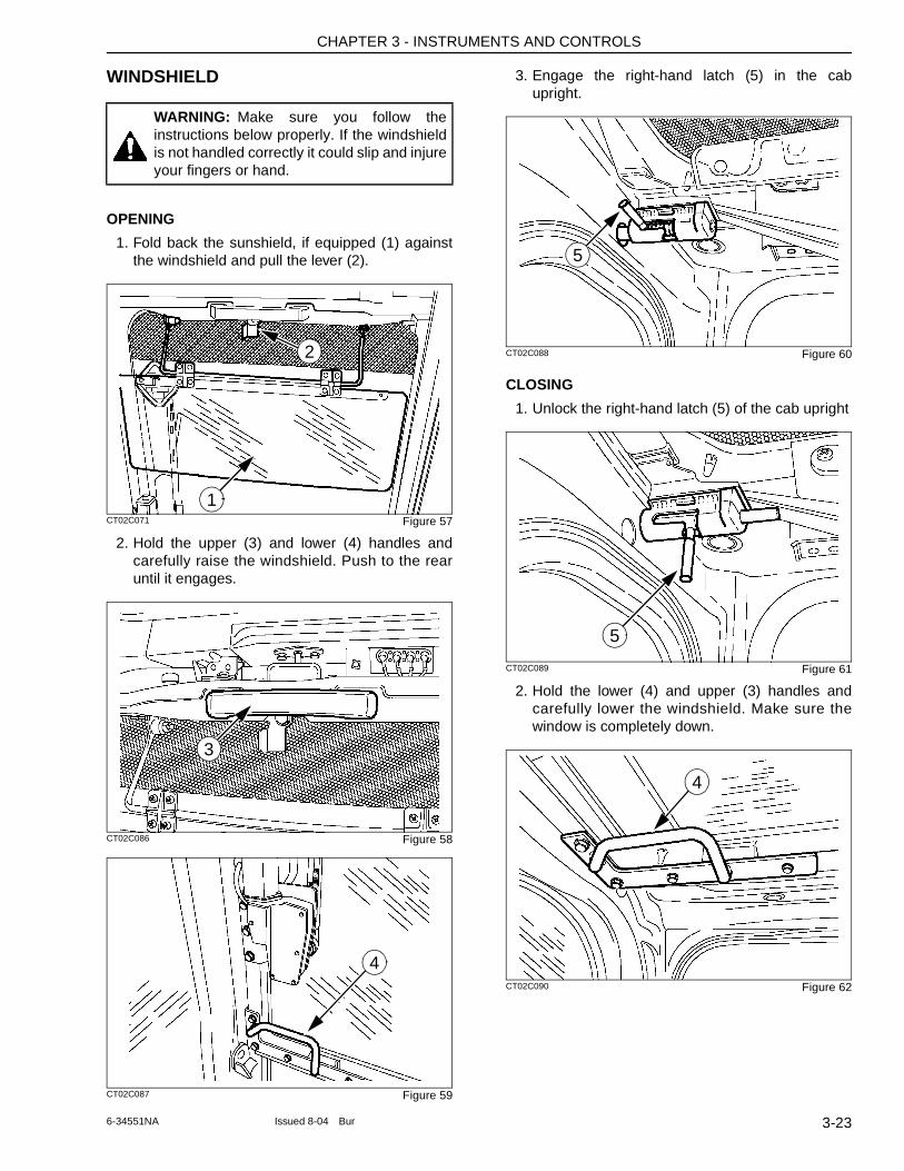
CHAPTER 3 - INSTRUMENTS AND CONTROLS
WINDSHIELD
OPENING
1. Fold back the sunshield, if equipped (1) against the windshield and pull the lever (2).
CT02C071 Figure 57
2. Hold the upper (3) and lower (4) handles and carefully raise the windshield. Push to the rear until it engages.
CT02C086 Figure 58
CT02C087 Figure 59
3. Engage the right-hand latch (5) in the cab upright.
CT02C088 Figure 60
CLOSING
1. Unlock the right-hand latch (5) of the cab upright
CT02C089 Figure 61
2. Hold the lower (4) and upper (3) handles and carefully lower the windshield. Make sure the window is completely down.
CT02C090 Figure 62
WARNING: Make sure you follow the instructions below properly. If the windshield is not handled correctly it could slip and injure your fingers or hand.
1
2
3
4
5
5
4
3-236-34551NA Issued 8-04 Bur
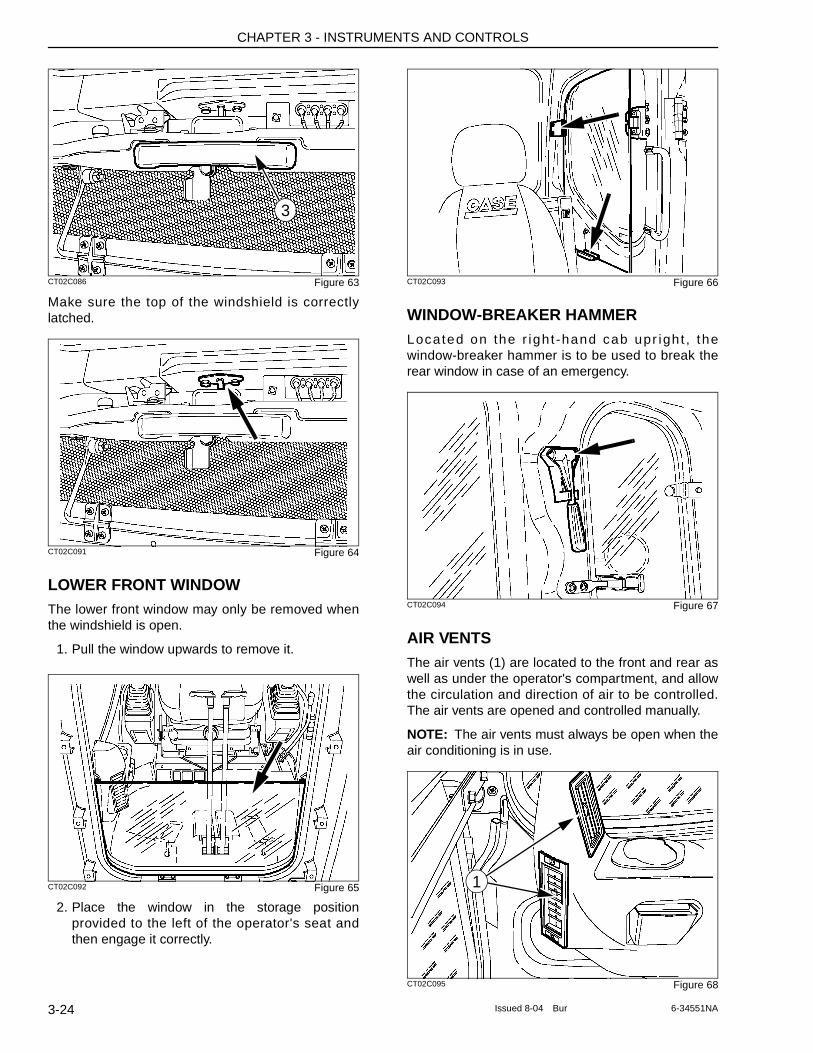
CHAPTER 3 - INSTRUMENTS AND CONTROLS
CT02C086 Figure 63
Make sure the top of the windshield is correctly latched.
CT02C091 Figure 64
LOWER FRONT WINDOWThe lower front window may only be removed when the windshield is open.
1. Pull the window upwards to remove it.
CT02C092 Figure 65
2. Place the window in the storage position provided to the left of the operator's seat and then engage it correctly.
CT02C093 Figure 66
WINDOW-BREAKER HAMMERLocated on the r igh t -hand cab upr igh t , the window-breaker hammer is to be used to break the rear window in case of an emergency.
CT02C094 Figure 67
AIR VENTSThe air vents (1) are located to the front and rear as well as under the operator's compartment, and allow the circulation and direction of air to be controlled. The air vents are opened and controlled manually.
NOTE: The air vents must always be open when the air conditioning is in use.
CT02C095 Figure 68
3
1
3-24 Issued 8-04 Bur 6-34551NA
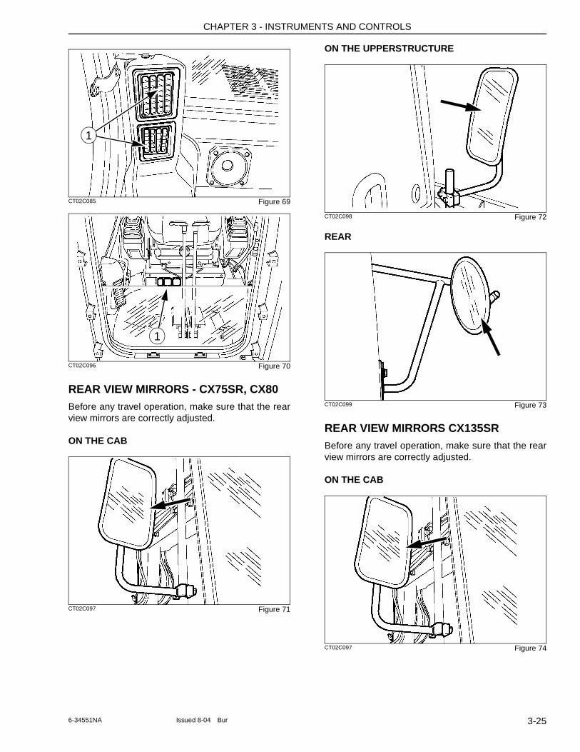
CHAPTER 3 - INSTRUMENTS AND CONTROLS
CT02C085 Figure 69
CT02C096 Figure 70
REAR VIEW MIRRORS - CX75SR, CX80Before any travel operation, make sure that the rear view mirrors are correctly adjusted.
ON THE CAB
CT02C097 Figure 71
ON THE UPPERSTRUCTURE
CT02C098 Figure 72
REAR
CT02C099 Figure 73
REAR VIEW MIRRORS CX135SRBefore any travel operation, make sure that the rear view mirrors are correctly adjusted.
ON THE CAB
CT02C097 Figure 74
1
1
3-256-34551NA Issued 8-04 Bur
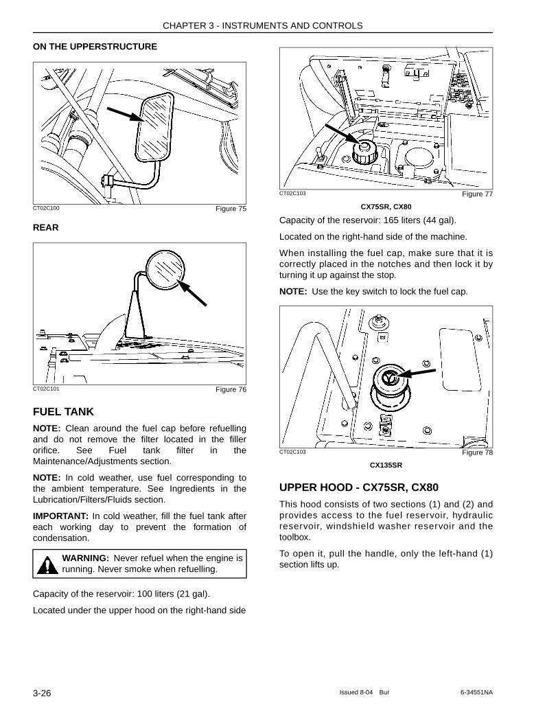
CHAPTER 3 - INSTRUMENTS AND CONTROLS
ON THE UPPERSTRUCTURE
CT02C100 Figure 75
REAR
CT02C101 Figure 76
FUEL TANKNOTE: Clean around the fuel cap before refuelling and do not remove the filter located in the filler orifice. See Fuel tank filter in the Maintenance/Adjustments section.
NOTE: In cold weather, use fuel corresponding to the ambient temperature. See Ingredients in the Lubrication/Filters/Fluids section.
IMPORTANT: In cold weather, fill the fuel tank after each working day to prevent the formation of condensation.
Capacity of the reservoir: 100 liters (21 gal).
Located under the upper hood on the right-hand side
CT02C103 Figure 77
CX75SR, CX80
Capacity of the reservoir: 165 liters (44 gal).
Located on the right-hand side of the machine.
When installing the fuel cap, make sure that it is correctly placed in the notches and then lock it by turning it up against the stop.
NOTE: Use the key switch to lock the fuel cap.
CT02C103 Figure 78
CX135SR
UPPER HOOD - CX75SR, CX80This hood consists of two sections (1) and (2) and provides access to the fuel reservoir, hydraulic reservoir, windshield washer reservoir and the toolbox.
To open it, pull the handle, only the left-hand (1) section lifts up.
WARNING: Never refuel when the engine is running. Never smoke when refuelling.
3-26 Issued 8-04 Bur 6-34551NA
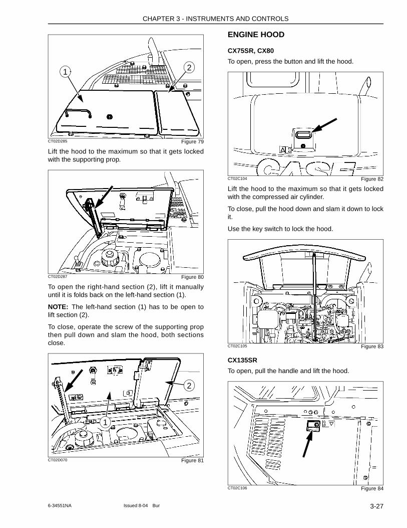
CHAPTER 3 - INSTRUMENTS AND CONTROLS
CT02D285 Figure 79
Lift the hood to the maximum so that it gets locked with the supporting prop.
CT02D287 Figure 80
To open the right-hand section (2), lift it manually until it is folds back on the left-hand section (1).
NOTE: The left-hand section (1) has to be open to lift section (2).
To close, operate the screw of the supporting prop then pull down and slam the hood, both sections close.
CT02D070 Figure 81
ENGINE HOOD
CX75SR, CX80
To open, press the button and lift the hood.
CT02C104 Figure 82
Lift the hood to the maximum so that it gets locked with the compressed air cylinder.
To close, pull the hood down and slam it down to lock it.
Use the key switch to lock the hood.
CT02C105 Figure 83
CX135SR
To open, pull the handle and lift the hood.
CT02C106 Figure 84
1 2
1
2
3-276-34551NA Issued 8-04 Bur
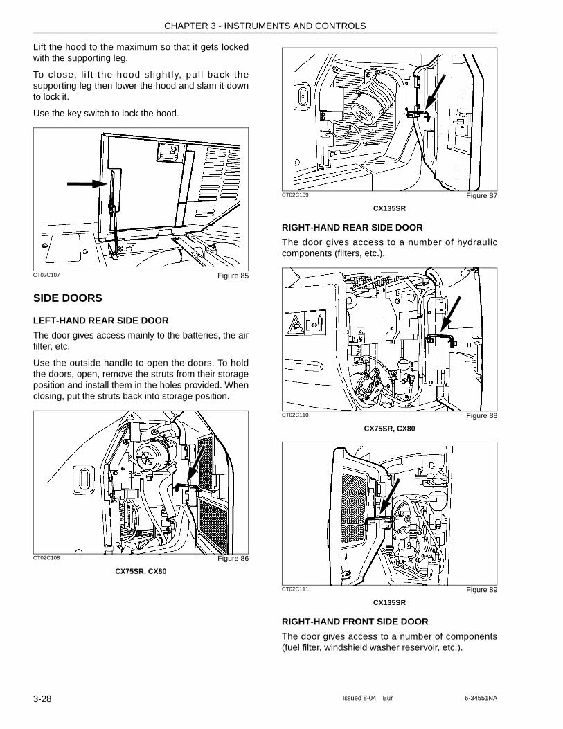
CHAPTER 3 - INSTRUMENTS AND CONTROLS
Lift the hood to the maximum so that it gets locked with the supporting leg.
To close, l i f t the hood sl ight ly, pul l back the supporting leg then lower the hood and slam it down to lock it.
Use the key switch to lock the hood.
CT02C107 Figure 85
SIDE DOORS
LEFT-HAND REAR SIDE DOOR
The door gives access mainly to the batteries, the air filter, etc.
Use the outside handle to open the doors. To hold the doors, open, remove the struts from their storage position and install them in the holes provided. When closing, put the struts back into storage position.
CT02C108 Figure 86
CX75SR, CX80
CT02C109 Figure 87
CX135SR
RIGHT-HAND REAR SIDE DOOR
The door gives access to a number of hydraulic components (filters, etc.).
CT02C110 Figure 88
CX75SR, CX80
CT02C111 Figure 89
CX135SR
RIGHT-HAND FRONT SIDE DOOR
The door gives access to a number of components (fuel filter, windshield washer reservoir, etc.).
3-28 Issued 8-04 Bur 6-34551NA
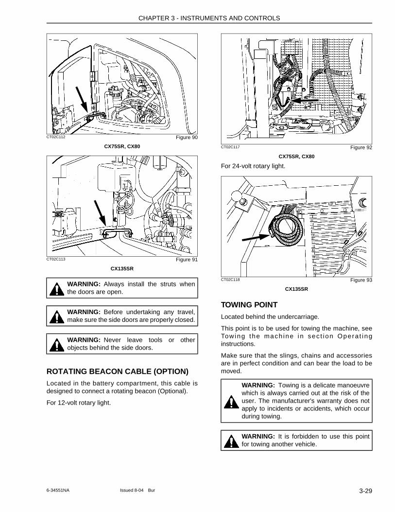
CHAPTER 3 - INSTRUMENTS AND CONTROLS
CT02C112 Figure 90
CX75SR, CX80
CT02C113 Figure 91
CX135SR
ROTATING BEACON CABLE (OPTION)Located in the battery compartment, this cable is designed to connect a rotating beacon (Optional).
For 12-volt rotary light.
CT02C117 Figure 92
CX75SR, CX80
For 24-volt rotary light.
CT02C118 Figure 93
CX135SR
TOWING POINTLocated behind the undercarriage.
This point is to be used for towing the machine, see Towing the mach ine in sec t i on Opera t i ng instructions.
Make sure that the slings, chains and accessories are in perfect condition and can bear the load to be moved.
WARNING: Always install the struts when the doors are open.
WARNING: Before undertaking any travel, make sure the side doors are properly closed.
WARNING: Never leave tools or other objects behind the side doors.
WARNING: Towing is a delicate manoeuvre which is always carried out at the risk of the user. The manufacturer's warranty does not apply to incidents or accidents, which occur during towing.
WARNING: It is forbidden to use this point for towing another vehicle.
3-296-34551NA Issued 8-04 Bur
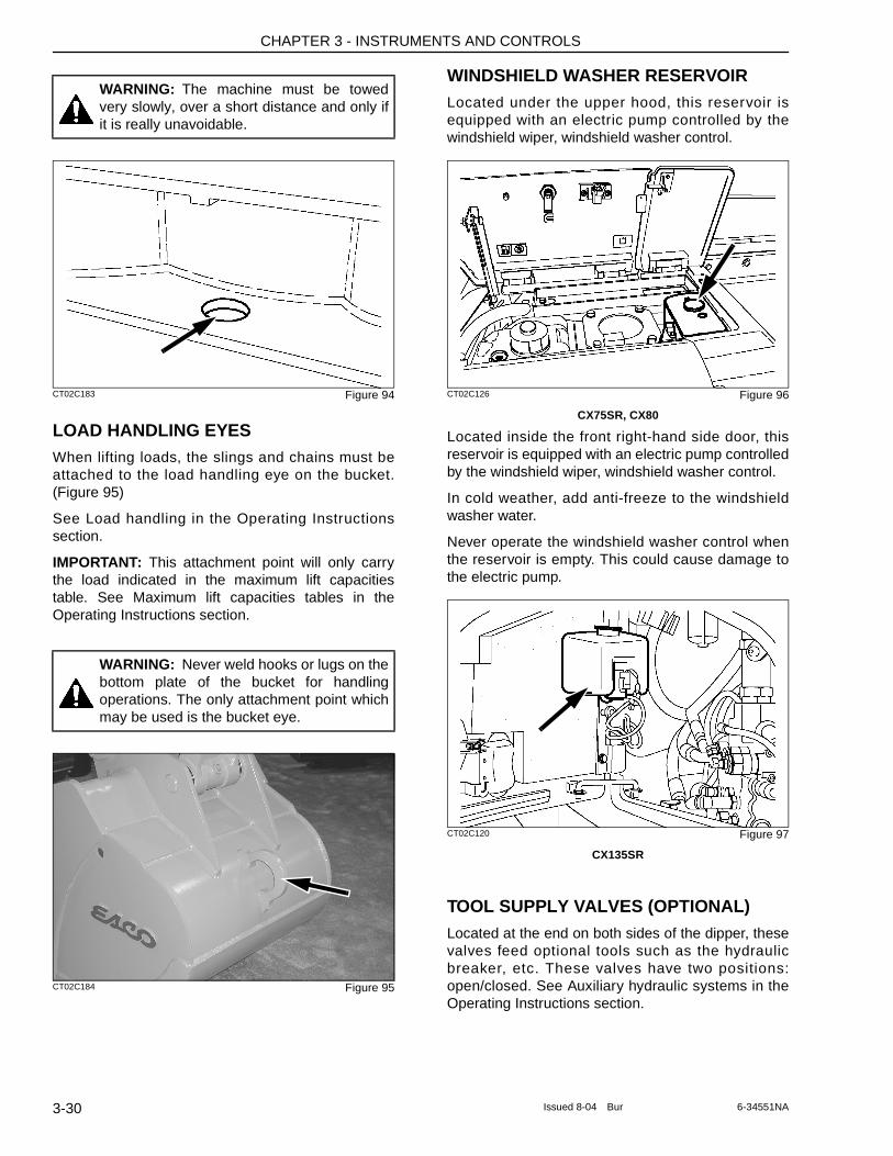
CHAPTER 3 - INSTRUMENTS AND CONTROLS
CT02C183 Figure 94
LOAD HANDLING EYESWhen lifting loads, the slings and chains must be attached to the load handling eye on the bucket. (Figure 95)
See Load handling in the Operating Instructions section.
IMPORTANT: This attachment point will only carry the load indicated in the maximum lift capacities table. See Maximum lift capacities tables in the Operating Instructions section.
CT02C184 Figure 95
WINDSHIELD WASHER RESERVOIRLocated under the upper hood, this reservoir is equipped with an electric pump controlled by the windshield wiper, windshield washer control.
CT02C126 Figure 96
CX75SR, CX80
Located inside the front right-hand side door, this reservoir is equipped with an electric pump controlled by the windshield wiper, windshield washer control.
In cold weather, add anti-freeze to the windshield washer water.
Never operate the windshield washer control when the reservoir is empty. This could cause damage to the electric pump.
CT02C120 Figure 97
CX135SR
TOOL SUPPLY VALVES (OPTIONAL)Located at the end on both sides of the dipper, these valves feed optional tools such as the hydraulic breaker, etc. These valves have two positions: open/closed. See Auxiliary hydraulic systems in the Operating Instructions section.
WARNING: The machine must be towed very slowly, over a short distance and only if it is really unavoidable.
WARNING: Never weld hooks or lugs on the bottom plate of the bucket for handling operations. The only attachment point which may be used is the bucket eye.
3-30 Issued 8-04 Bur 6-34551NA
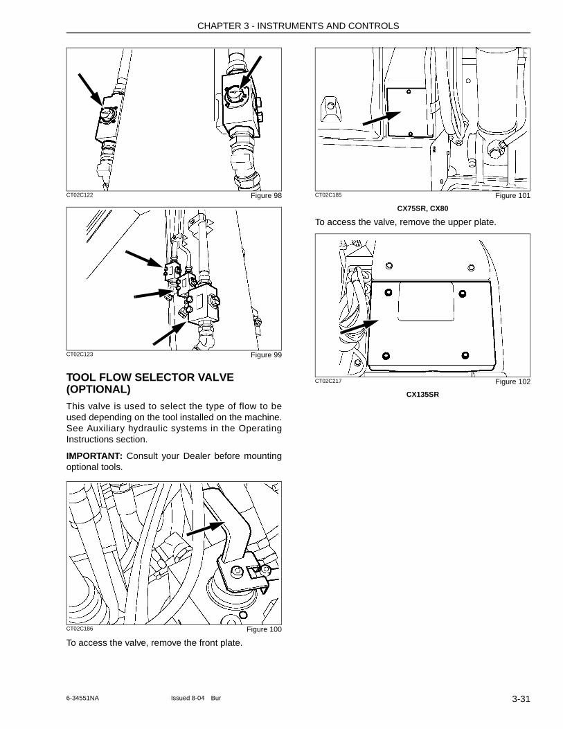
CHAPTER 3 - INSTRUMENTS AND CONTROLS
CT02C122 Figure 98
CT02C123 Figure 99
TOOL FLOW SELECTOR VALVE (OPTIONAL)This valve is used to select the type of flow to be used depending on the tool installed on the machine. See Auxiliary hydraulic systems in the Operating Instructions section.
IMPORTANT: Consult your Dealer before mounting optional tools.
CT02C186 Figure 100
To access the valve, remove the front plate.
CT02C185 Figure 101
CX75SR, CX80
To access the valve, remove the upper plate.
CT02C217 Figure 102
CX135SR
3-316-34551NA Issued 8-04 Bur

CHAPTER 3 - INSTRUMENTS AND CONTROLS
3-32 Issued 8-04 Bur 6-34551NA
CHAPTER 4 - OPERATING INSTRUCTIONS
Chapter 4
OPERATING INSTRUCTIONS
TABLE OF CONTENTS
BEFORE OPERATING THE MACHINE . . . . . . . . . . . . . . . . . . . . . . . . . . . . . . . . . . . . . . . . . . . . . . . . . . . . . . . . 4-3
OPERATING THE MACHINE . . . . . . . . . . . . . . . . . . . . . . . . . . . . . . . . . . . . . . . . . . . . . . . . . . . . . . . . . . . . . . . . 4-3
RUN-IN PERIOD . . . . . . . . . . . . . . . . . . . . . . . . . . . . . . . . . . . . . . . . . . . . . . . . . . . . . . . . . . . . . . . . . . . . . . . . . 4-4After the First 50 Hours . . . . . . . . . . . . . . . . . . . . . . . . . . . . . . . . . . . . . . . . . . . . . . . . . . . . . . . . . . . . . . . . . . 4-4After the First 250 Hours . . . . . . . . . . . . . . . . . . . . . . . . . . . . . . . . . . . . . . . . . . . . . . . . . . . . . . . . . . . . . . . . . 4-4
STARTING THE ENGINE . . . . . . . . . . . . . . . . . . . . . . . . . . . . . . . . . . . . . . . . . . . . . . . . . . . . . . . . . . . . . . . . . . 4-4
BRINGING THE MACHINE UP TO OPERATING TEMPERATURE . . . . . . . . . . . . . . . . . . . . . . . . . . . . . . . . . . 4-5Bringing the engine up to operating temperature . . . . . . . . . . . . . . . . . . . . . . . . . . . . . . . . . . . . . . . . . . . . . . . 4-6Hydraulic Fluid Warm-up . . . . . . . . . . . . . . . . . . . . . . . . . . . . . . . . . . . . . . . . . . . . . . . . . . . . . . . . . . . . . . . . . 4-6
ENGINE OPERATION . . . . . . . . . . . . . . . . . . . . . . . . . . . . . . . . . . . . . . . . . . . . . . . . . . . . . . . . . . . . . . . . . . . . . 4-6
STOPPING THE ENGINE . . . . . . . . . . . . . . . . . . . . . . . . . . . . . . . . . . . . . . . . . . . . . . . . . . . . . . . . . . . . . . . . . . 4-6In the Event of An Emergency . . . . . . . . . . . . . . . . . . . . . . . . . . . . . . . . . . . . . . . . . . . . . . . . . . . . . . . . . . . . . 4-7
OPERATING THE MACHINE IN COLD WEATHER . . . . . . . . . . . . . . . . . . . . . . . . . . . . . . . . . . . . . . . . . . . . . . 4-7Battery . . . . . . . . . . . . . . . . . . . . . . . . . . . . . . . . . . . . . . . . . . . . . . . . . . . . . . . . . . . . . . . . . . . . . . . . . . . . . . . 4-7Fuel . . . . . . . . . . . . . . . . . . . . . . . . . . . . . . . . . . . . . . . . . . . . . . . . . . . . . . . . . . . . . . . . . . . . . . . . . . . . . . . . . 4-7Engine Oil . . . . . . . . . . . . . . . . . . . . . . . . . . . . . . . . . . . . . . . . . . . . . . . . . . . . . . . . . . . . . . . . . . . . . . . . . . . . . 4-7Hydraulic Fluid . . . . . . . . . . . . . . . . . . . . . . . . . . . . . . . . . . . . . . . . . . . . . . . . . . . . . . . . . . . . . . . . . . . . . . . . . 4-7Coolant Solution . . . . . . . . . . . . . . . . . . . . . . . . . . . . . . . . . . . . . . . . . . . . . . . . . . . . . . . . . . . . . . . . . . . . . . . . 4-7
OPERATING THE MACHINE IN HOT WEATHER . . . . . . . . . . . . . . . . . . . . . . . . . . . . . . . . . . . . . . . . . . . . . . . 4-8
OPERATION . . . . . . . . . . . . . . . . . . . . . . . . . . . . . . . . . . . . . . . . . . . . . . . . . . . . . . . . . . . . . . . . . . . . . . . . . . . . 4-8
MACHINE TRAVEL . . . . . . . . . . . . . . . . . . . . . . . . . . . . . . . . . . . . . . . . . . . . . . . . . . . . . . . . . . . . . . . . . . . . . . . 4-8
TRANSPORT POSITION FOR 2.85 M (9 FT. 4 IN) ARM CX135SR . . . . . . . . . . . . . . . . . . . . . . . . . . . . . . . . . 4-10
TRANSPORTING THE MACHINE . . . . . . . . . . . . . . . . . . . . . . . . . . . . . . . . . . . . . . . . . . . . . . . . . . . . . . . . . . . 4-11By Rail . . . . . . . . . . . . . . . . . . . . . . . . . . . . . . . . . . . . . . . . . . . . . . . . . . . . . . . . . . . . . . . . . . . . . . . . . . . . . . 4-11On a Trailer . . . . . . . . . . . . . . . . . . . . . . . . . . . . . . . . . . . . . . . . . . . . . . . . . . . . . . . . . . . . . . . . . . . . . . . . . . 4-11Unloading . . . . . . . . . . . . . . . . . . . . . . . . . . . . . . . . . . . . . . . . . . . . . . . . . . . . . . . . . . . . . . . . . . . . . . . . . . . . 4-13
HANDLING THE MACHINE . . . . . . . . . . . . . . . . . . . . . . . . . . . . . . . . . . . . . . . . . . . . . . . . . . . . . . . . . . . . . . . . 4-14
OPERATING THE MACHINE IN WATER . . . . . . . . . . . . . . . . . . . . . . . . . . . . . . . . . . . . . . . . . . . . . . . . . . . . . 4-14
PARKING THE MACHINE . . . . . . . . . . . . . . . . . . . . . . . . . . . . . . . . . . . . . . . . . . . . . . . . . . . . . . . . . . . . . . . . . 4-14
OPERATING THE MACHINE ON SLOPING GROUND . . . . . . . . . . . . . . . . . . . . . . . . . . . . . . . . . . . . . . . . . . 4-15
TOWING THE MACHINE . . . . . . . . . . . . . . . . . . . . . . . . . . . . . . . . . . . . . . . . . . . . . . . . . . . . . . . . . . . . . . . . . . 4-15
OPERATING THE BUCKET . . . . . . . . . . . . . . . . . . . . . . . . . . . . . . . . . . . . . . . . . . . . . . . . . . . . . . . . . . . . . . . . 4-16Filling . . . . . . . . . . . . . . . . . . . . . . . . . . . . . . . . . . . . . . . . . . . . . . . . . . . . . . . . . . . . . . . . . . . . . . . . . . . . . . . 4-16Excavating method . . . . . . . . . . . . . . . . . . . . . . . . . . . . . . . . . . . . . . . . . . . . . . . . . . . . . . . . . . . . . . . . . . . . . 4-16
LOWERING THE ATTACHMENT IN THE EVENT OF A MACHINE FAILURE . . . . . . . . . . . . . . . . . . . . . . . . . 4-16auxiliary hydraulic circuits . . . . . . . . . . . . . . . . . . . . . . . . . . . . . . . . . . . . . . . . . . . . . . . . . . . . . . . . . . . . . . . 4-17Configuring the Hydraulic Breaker, Demolition Grab to A Flow or Bucket . . . . . . . . . . . . . . . . . . . . . . . . . . . 4-17Two Flow Demolition Grab Configuration . . . . . . . . . . . . . . . . . . . . . . . . . . . . . . . . . . . . . . . . . . . . . . . . . . . . 4-18
MACHINE STORAGE . . . . . . . . . . . . . . . . . . . . . . . . . . . . . . . . . . . . . . . . . . . . . . . . . . . . . . . . . . . . . . . . . . . . 4-20Preparation for storage . . . . . . . . . . . . . . . . . . . . . . . . . . . . . . . . . . . . . . . . . . . . . . . . . . . . . . . . . . . . . . . . . 4-20Periodical checks . . . . . . . . . . . . . . . . . . . . . . . . . . . . . . . . . . . . . . . . . . . . . . . . . . . . . . . . . . . . . . . . . . . . . . 4-20Starting up after storage . . . . . . . . . . . . . . . . . . . . . . . . . . . . . . . . . . . . . . . . . . . . . . . . . . . . . . . . . . . . . . . . . 4-21
4-1Issued 8-04 Bur 6-34551NA

CHAPTER 4 - OPERATING INSTRUCTIONS
4-2 Issued 8-04 Bur 6-34551NA
CHAPTER 4 - OPERATING INSTRUCTIONS
BEFORE OPERATING THE MACHINE
Before operating this machine, be sure to do the following:
1. Check the level of all fluids (engine oil, hydraulic fluid and coolant) and make sure that the fluids and lubr icants are suitable for prevai l ing cond i t ions. See Ingred ien ts i n t he Lubrication/Filters/Fluids section and Operating the machine in cold weather.
2. Carry out the daily maintenance operations. See section Servicing intervals.
3. Inspect the machine, look for any signs of possible leakage and check the hoses. Tighten o r r ep lace as necessar y. See sec t i on Maintenance/Adjustments.
4. See Run-in period if the machine is new or if the engine has been reconditioned.
5. Check the track assemblies. See Tracks in the Maintenance/Adjustments section.
6. Clean the steps and access handles. Grease, oil, mud or ice (in winter) on the steps and access handles can causes accidents. Make sure they are kept clean at all times.
7. Clean or replace any decals which are illegible. See Decals in the Safety/Decals/Hand signals section.
8. Make sure that the engine hood and the side doors are properly closed and latched.
9. Secure the cab door in either fully closed or fully opened position.
10. Remove any obstructions which hinder visibility. Clean the windshield, the windows and the rear view mirrors.
11. Check that no tools or other items have been left on the machine (be it on the undercarriage or the uppers t r uc tu re ) o r i n the opera to r ' s compartment.
12. Make sure nobody is on or under the machine. The operator must be alone on the machine.
13. Make sure nobody is standing in the machine working area.
14. Find out about current safety measures in use on the work site.
15. Work out a convenient means of escape from the machine (emergency exit via the windshield, the rear window glass) in the event of the cab door being jammed or the machine turning over. See Windsh ie ld in the Controls/Instruments/Accessories section.
16. Before undertaking any travel or working operations during hours of darkness, make sure the lighting and signalling equipment is fully operative.
OPERATING THE MACHINE
When operating the machine, be sure to do the following:
1. When starting the engine, be sure to use the correct procedure for the prevailing weather conditions. See Starting the engine.
2. Regularly consult the hourmeter to ensure that a l l ser v ic ing opera t ions are car r ied out punctually. See section Servicing intervals.
3. If you use your machine in particularly harsh conditions (dusty or corrosive atmosphere), the se r v i c ing i n te r va ls shou ld be reduced accordingly.
4. Take note of the locations of pipes/cables before starting work.
5. Do not work near overhead high-voltage electric l ines without checking beforehand that all necessary measures have been taken to respect the safest distances:
Less than 57 000 volts: 3 metres ( 10 ft.)
More than 57 000 volts: 5 metres (16 ft.)
6. When working on a public highway, use standard traffic signs and take into consideration the working range of the upperstructure and its attachments. Local regulations stipulate the number, type and location of reflector strips.
7. Never operate the working or travel controls unless you are properly seated in the operator's seat with the seat belt correctly fastened.
8. Modify your driving to suit the type of work and working conditions. See Operating instructions in the Job Site Operation section.
9. Do not allow anyone within the machine's operating radius. Stop all operations unti l everyone has moved away.
10. Operate all controls gradually to ensure smooth machine operation.
WARNING: Do not attempt to operate this machine unless you have first read and perfectly understood the safety messages and instructions appearing in this manual.
WARNING: Check all controls and safety devices in a safe, open area before starting work.
4-36-34551NA Issued 8-04 Bur
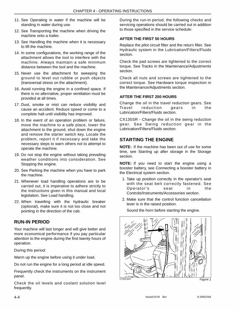
CHAPTER 4 - OPERATING INSTRUCTIONS
11. See Operating in water if the machine will be standing in water during use.
12. See Transporting the machine when driving the machine onto a trailer.
13. See Handling the machine when it is necessary to lift the machine.
14. In some configurations, the working range of the attachment allows the tool to interfere with the machine. Always maintain a safe minimum distance between the tool and the machine.
15. Never use the attachment for sweeping the ground to level out rubble or push objects (transversal stress on the attachment).
16. Avoid running the engine in a confined space. If there is no alternative, proper ventilation must be provided at all times.
17. Dust, smoke or mist can reduce visibility and cause an accident. Reduce speed or come to a complete halt until visibility has improved.
18. In the event of an operation problem or failure, move the machine to a safe place, lower the attachment to the ground, shut down the engine and remove the starter switch key. Locate the problem, report it if necessary and take the necessary steps to warn others not to attempt to operate the machine.
19. Do not stop the engine without taking prevailing weather conditions into consideration. See Stopping the engine.
20. See Parking the machine when you have to park the machine.
21. Whenever load handling operations are to be carried out, it is imperative to adhere strictly to the instructions given in this manual and local legislation. See Load handling.
22. When travelling with the hydraulic breaker (optional), make sure it is not too close and not pointing in the direction of the cab.
RUN-IN PERIODYour machine will last longer and will give better and more economical performance if you pay particular attention to the engine during the first twenty hours of operation.
During this period:
Warm up the engine before using it under load.
Do not run the engine for a long period at idle speed.
Frequently check the instruments on the instrument panel.
Check the oil levels and coolant solution level frequently.
During the run-in period, the following checks and servicing operations should be carried out in addition to those specified in the service schedule:
AFTER THE FIRST 50 HOURS
Replace the pilot circuit filter and the return filter. See Hydraulic system in the Lubrication/Filters/Fluids section.
Check the pad screws are tightened to the correct torque. See Tracks in the Maintenance/Adjustments section.
Check all nuts and screws are tightened to the correct torque. See Hardware torque inspection in the Maintenance/Adjustments section.
AFTER THE FIRST 250 HOURS
Change the oil in the travel reduction gears. See Trave l reduc t ion gears i n the Lubrication/Filters/Fluids section.
CX135SR - Change the oil in the swing reduction gea r. See Sw ing reduc t ion gear i n the Lubrication/Filters/Fluids section.
STARTING THE ENGINENOTE: If the machine has been out of use for some time, see Starting up after storage in the Storage section.
NOTE: If you need to start the engine using a booster battery, see Connecting a booster battery in the Electrical system section.
1. Take up position correctly in the operator's seat with the seat belt correctly fastened. See Opera to r ' s seat i n the Controls/Instruments/Accessories section.
2. Make sure that the control function cancellation lever is in the raised position.
Sound the horn before starting the engine.
CT02C037 Figure 1
4-4 Issued 8-04 Bur 6-34551NA
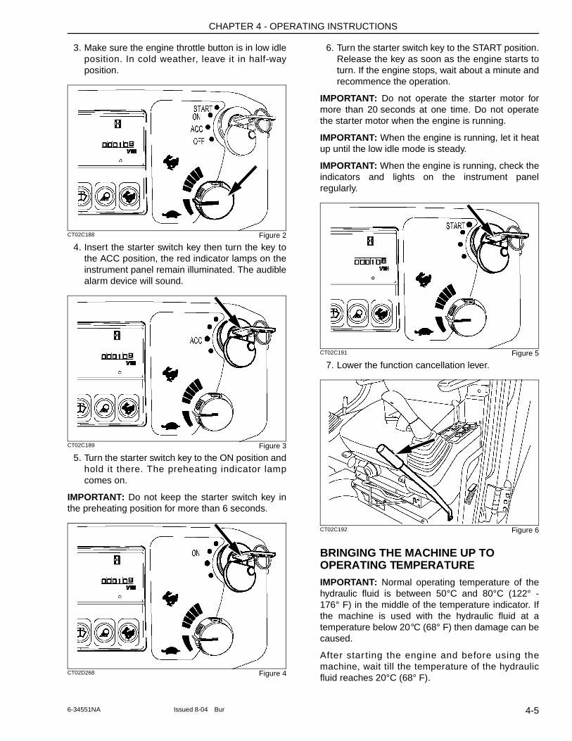
CHAPTER 4 - OPERATING INSTRUCTIONS
3. Make sure the engine throttle button is in low idle position. In cold weather, leave it in half-way position.
CT02C188 Figure 2
4. Insert the starter switch key then turn the key to the ACC position, the red indicator lamps on the instrument panel remain illuminated. The audible alarm device will sound.
CT02C189 Figure 3
5. Turn the starter switch key to the ON position and hold it there. The preheating indicator lamp comes on.
IMPORTANT: Do not keep the starter switch key in the preheating position for more than 6 seconds.
CT02D268 Figure 4
6. Turn the starter switch key to the START position. Release the key as soon as the engine starts to turn. If the engine stops, wait about a minute and recommence the operation.
IMPORTANT: Do not operate the starter motor for more than 20 seconds at one time. Do not operate the starter motor when the engine is running.
IMPORTANT: When the engine is running, let it heat up until the low idle mode is steady.
IMPORTANT: When the engine is running, check the indicators and lights on the instrument panel regularly.
CT02C191 Figure 5
7. Lower the function cancellation lever.
CT02C192 Figure 6
BRINGING THE MACHINE UP TO OPERATING TEMPERATUREIMPORTANT: Normal operating temperature of the hydraulic fluid is between 50°C and 80°C (122° - 176° F) in the middle of the temperature indicator. If the machine is used with the hydraulic fluid at a temperature below 20°C (68° F) then damage can be caused.
After star ting the engine and before using the machine, wait till the temperature of the hydraulic fluid reaches 20°C (68° F).
4-56-34551NA Issued 8-04 Bur
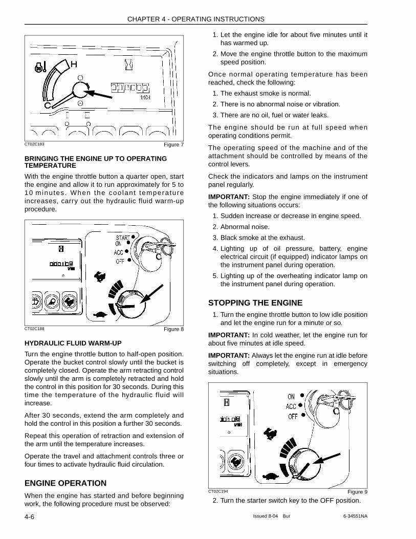
CHAPTER 4 - OPERATING INSTRUCTIONS
CT02C193 Figure 7
BRINGING THE ENGINE UP TO OPERATING TEMPERATURE
With the engine throttle button a quarter open, start the engine and allow it to run approximately for 5 to 10 minutes . When the coo lant tempera ture increases, carry out the hydraulic fluid warm-up procedure.
CT02C188 Figure 8
HYDRAULIC FLUID WARM-UP
Turn the engine throttle button to half-open position. Operate the bucket control slowly until the bucket is completely closed. Operate the arm retracting control slowly until the arm is completely retracted and hold the control in this position for 30 seconds. During this time the temperature of the hydraulic fluid will increase.
After 30 seconds, extend the arm completely and hold the control in this position a further 30 seconds.
Repeat this operation of retraction and extension of the arm until the temperature increases.
Operate the travel and attachment controls three or four times to activate hydraulic fluid circulation.
ENGINE OPERATIONWhen the engine has started and before beginning work, the following procedure must be observed:
1. Let the engine idle for about five minutes until it has warmed up.
2. Move the engine throttle button to the maximum speed position.
Once normal operating temperature has been reached, check the following:
1. The exhaust smoke is normal.
2. There is no abnormal noise or vibration.
3. There are no oil, fuel or water leaks.
The engine should be run at full speed when operating conditions permit.
The operating speed of the machine and of the attachment should be controlled by means of the control levers.
Check the indicators and lamps on the instrument panel regularly.
IMPORTANT: Stop the engine immediately if one of the following situations occurs:
1. Sudden increase or decrease in engine speed.
2. Abnormal noise.
3. Black smoke at the exhaust.
4. Lighting up of oil pressure, battery, engine electrical circuit (if equipped) indicator lamps on the instrument panel during operation.
5. Lighting up of the overheating indicator lamp on the instrument panel during operation.
STOPPING THE ENGINE1. Turn the engine throttle button to low idle position
and let the engine run for a minute or so.
IMPORTANT: In cold weather, let the engine run for about five minutes at idle speed.
IMPORTANT: Always let the engine run at idle before switching off completely, except in emergency situations.
CT02C194 Figure 9
2. Turn the starter switch key to the OFF position.
4-6 Issued 8-04 Bur 6-34551NA
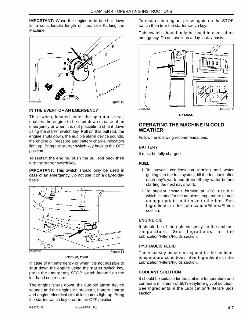
CHAPTER 4 - OPERATING INSTRUCTIONS
IMPORTANT: When the engine is to be shut down for a considerable length of time, see Parking the Machine.
CT02C195 Figure 10
IN THE EVENT OF AN EMERGENCY
This switch, located under the operator’s seat, enables the engine to be shut down in case of an emergency or when it is not possible to shut it down using the starter switch key. Pull on this pull rod, the engine shuts down, the audible alarm device sounds, the engine oil pressure and battery charge indicators light up. Bring the starter switch key back to the OFF position.
To restart the engine, push the pull rod back then turn the starter switch key.
IMPORTANT: This switch should only be used in case of an emergency. Do not use it on a day-to-day basis.
CT02C052 Figure 11
CX75SR, CX80
In case of an emergency or when it is not possible to shut down the engine using the starter switch key, press the emergency STOP switch located on the left-hand control arm.
The engine shuts down, the audible alarm device sounds and the engine oil pressure, battery charge and engine electrical circuit indicators light up. Bring the starter switch key back to the OFF position.
To restart the engine, press again on the STOP switch then turn the starter switch key.
This switch should only be used in case of an emergency. Do not use it on a day-to-day basis.
CT02C225 Figure 12
CX135SR
OPERATING THE MACHINE IN COLD WEATHERFollow the following recommendations:
BATTERY
It must be fully charged.
FUEL
1. To prevent condensation forming and water getting into the fuel system, fill the fuel tank after each day's work and drain off any water before starting the next day's work.
2. To prevent crystals forming at -2°C, use fuel which is rated for the ambient temperature or add an appropr iate antifreeze to the fuel. See Ingredients in the Lubrication/Filters/Fluids section.
ENGINE OIL
It should be of the right viscosity for the ambient tempera tu re. See Ingred ien ts i n the Lubrication/Filters/Fluids section.
HYDRAULIC FLUID
The viscosity must correspond to the ambient temperature conditions. See Ingredients in the Lubrication/Filters/Fluids section.
COOLANT SOLUTION
It should be suitable for the ambient temperature and contain a minimum of 50% ethylene glycol solution. See Ingredients in the Lubrication/Filters/Fluids section.
4-76-34551NA Issued 8-04 Bur
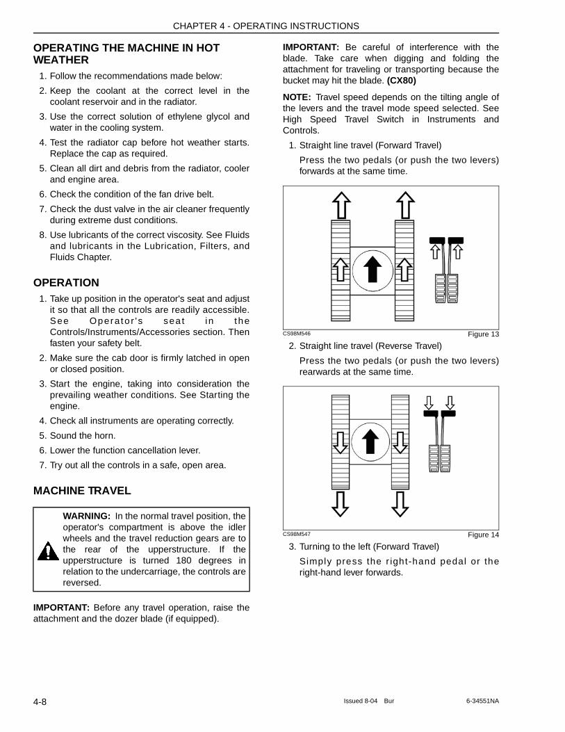
CHAPTER 4 - OPERATING INSTRUCTIONS
OPERATING THE MACHINE IN HOT WEATHER
1. Follow the recommendations made below:
2. Keep the coolant at the correct level in the coolant reservoir and in the radiator.
3. Use the correct solution of ethylene glycol and water in the cooling system.
4. Test the radiator cap before hot weather starts. Replace the cap as required.
5. Clean all dirt and debris from the radiator, cooler and engine area.
6. Check the condition of the fan drive belt.
7. Check the dust valve in the air cleaner frequently during extreme dust conditions.
8. Use lubricants of the correct viscosity. See Fluids and lubricants in the Lubrication, Filters, and Fluids Chapter.
OPERATION1. Take up position in the operator's seat and adjust
it so that all the controls are readily accessible. See Opera to r ' s sea t i n the Controls/Instruments/Accessories section. Then fasten your safety belt.
2. Make sure the cab door is firmly latched in open or closed position.
3. Start the engine, taking into consideration the prevailing weather conditions. See Starting the engine.
4. Check all instruments are operating correctly.
5. Sound the horn.
6. Lower the function cancellation lever.
7. Try out all the controls in a safe, open area.
MACHINE TRAVEL
IMPORTANT: Before any travel operation, raise the attachment and the dozer blade (if equipped).
IMPORTANT: Be careful of interference with the blade. Take care when digging and folding the attachment for traveling or transporting because the bucket may hit the blade. (CX80)
NOTE: Travel speed depends on the tilting angle of the levers and the travel mode speed selected. See High Speed Travel Switch in Instruments and Controls.
1. Straight line travel (Forward Travel)
Press the two pedals (or push the two levers) forwards at the same time.
CS98M546 Figure 13
2. Straight line travel (Reverse Travel)
Press the two pedals (or push the two levers) rearwards at the same time.
CS98M547 Figure 14
3. Turning to the left (Forward Travel)
Simply press the r ight-hand pedal or the right-hand lever forwards.
WARNING: In the normal travel position, the operator's compartment is above the idler wheels and the travel reduction gears are to the rear of the upperstructure. If the upperstructure is turned 180 degrees in relation to the undercarriage, the controls are reversed.
4-8 Issued 8-04 Bur 6-34551NA
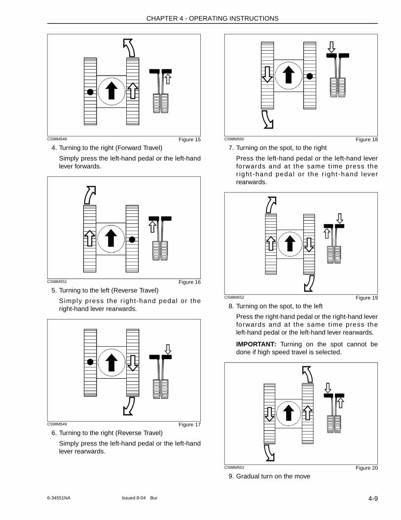
CHAPTER 4 - OPERATING INSTRUCTIONS
CS98M548 Figure 15
4. Turning to the right (Forward Travel)
Simply press the left-hand pedal or the left-hand lever forwards.
CS98M551 Figure 16
5. Turning to the left (Reverse Travel)
Simply press the r ight-hand pedal or the right-hand lever rearwards.
CS98M549 Figure 17
6. Turning to the right (Reverse Travel)
Simply press the left-hand pedal or the left-hand lever rearwards.
CS98M550 Figure 18
7. Turning on the spot, to the right
Press the left-hand pedal or the left-hand lever forwards and at the same t ime press the r ight-hand peda l or the r ight -hand lever rearwards.
CS98M552 Figure 19
8. Turning on the spot, to the left
Press the right-hand pedal or the right-hand lever forwards and at the same t ime press the left-hand pedal or the left-hand lever rearwards.
IMPORTANT: Turning on the spot cannot be done if high speed travel is selected.
CS98M553 Figure 20
9. Gradual turn on the move
4-96-34551NA Issued 8-04 Bur
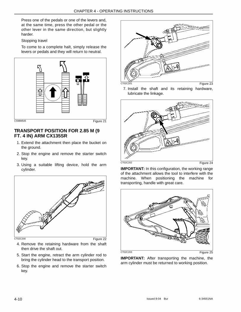
CHAPTER 4 - OPERATING INSTRUCTIONS
Press one of the pedals or one of the levers and, at the same time, press the other pedal or the other lever in the same direction, but slightly harder.
Stopping travel
To come to a complete halt, simply release the levers or pedals and they will return to neutral.
CS98M545 Figure 21
TRANSPORT POSITION FOR 2.85 M (9 FT. 4 IN) ARM CX135SR
1. Extend the attachment then place the bucket on the ground.
2. Stop the engine and remove the starter switch key.
3. Using a suitable lifting device, hold the arm cylinder.
CT02C200 Figure 22
4. Remove the retaining hardware from the shaft then drive the shaft out.
5. Start the engine, retract the arm cylinder rod to bring the cylinder head to the transport position.
6. Stop the engine and remove the starter switch key.
CT02C201 Figure 23
7. Install the shaft and its retaining hardware, lubricate the linkage.
CT02C202 Figure 24
IMPORTANT: In this configuration, the working range of the attachment allows the tool to interfere with the machine. When positioning the machine for transporting, handle with great care.
CT02C203 Figure 25
IMPORTANT: After transporting the machine, the arm cylinder must be returned to working position.
4-10 Issued 8-04 Bur 6-34551NA
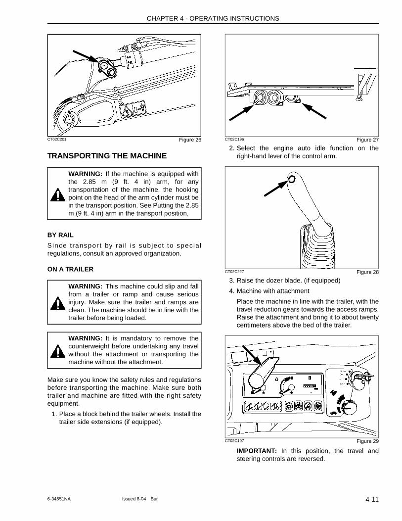
CHAPTER 4 - OPERATING INSTRUCTIONS
CT02C201 Figure 26
TRANSPORTING THE MACHINE
BY RAIL
Since t ranspor t by ra i l is subject to specia l regulations, consult an approved organization.
ON A TRAILER
Make sure you know the safety rules and regulations before transporting the machine. Make sure both trailer and machine are fitted with the right safety equipment.
1. Place a block behind the trailer wheels. Install the trailer side extensions (if equipped).
CT02C196 Figure 27
2. Select the engine auto idle function on the right-hand lever of the control arm.
CT02C227 Figure 28
3. Raise the dozer blade. (if equipped)
4. Machine with attachment
Place the machine in line with the trailer, with the travel reduction gears towards the access ramps. Raise the attachment and bring it to about twenty centimeters above the bed of the trailer.
CT02C197 Figure 29
IMPORTANT: In this position, the travel and steering controls are reversed.
WARNING: If the machine is equipped with the 2.85 m (9 ft. 4 in) arm, for any transportation of the machine, the hooking point on the head of the arm cylinder must be in the transport position. See Putting the 2.85 m (9 ft. 4 in) arm in the transport position.
WARNING: This machine could slip and fall from a trailer or ramp and cause serious injury. Make sure the trailer and ramps are clean. The machine should be in line with the trailer before being loaded.
WARNING: It is mandatory to remove the counterweight before undertaking any travel without the attachment or transporting the machine without the attachment.
4-116-34551NA Issued 8-04 Bur
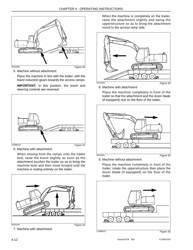
CHAPTER 4 - OPERATING INSTRUCTIONS
PDH0248 Figure 30
5. Machine without attachment
Place the machine in line with the trailer, with the travel reduction gears towards the access ramps.
IMPORTANT: In this position, the travel and steering controls are reversed.
CS99B518 Figure 31
6. Machine with attachment
When moving from the ramps onto the trailer bed, raise the boom slightly as soon as the attachment touches the trailer so as to bring the machine level and then move forward until the machine is resting entirely on the trailer.
PDH0249 Figure 32
7. Machine with attachment
When the machine is completely on the trailer, raise the attachment slightly and swing the upperstructure so as to bring the attachment round to the access ramp side.
PDH0250 Figure 33
8. Machine with attachment
Place the machine completely in front of the trailer so that the attachment and the dozer blade (if equipped) rest on the floor of the trailer.
PDH0251 Figure 34
9. Machine without attachment
Place the machine completely in front of the trailer, rotate the upperstructure then place the dozer blade (if equipped) on the floor of the trailer.
CS99B519 Figure 35
4-12 Issued 8-04 Bur 6-34551NA
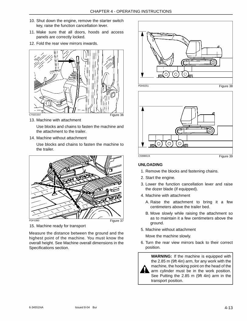
CHAPTER 4 - OPERATING INSTRUCTIONS
10. Shut down the engine, remove the starter switch key, raise the function cancellation lever.
11. Make sure that all doors, hoods and access panels are correctly locked.
12. Fold the rear view mirrors inwards.
CT02C037 Figure 36
13. Machine with attachment
Use blocks and chains to fasten the machine and the attachment to the trailer.
14. Machine without attachment
Use blocks and chains to fasten the machine to the trailer.
PDF0360 Figure 37
15. Machine ready for transport
Measure the distance between the ground and the highest point of the machine. You must know the overall height. See Machine overall dimensions in the Specifications section.
PDH0251 Figure 38
CS99B519 Figure 39
UNLOADING
1. Remove the blocks and fastening chains.
2. Start the engine.
3. Lower the function cancellation lever and raise the dozer blade (if equipped).
4. Machine with attachment
A. Raise the attachment to bring it a few centimeters above the trailer bed.
B. Move slowly while raising the attachment so as to maintain it a few centimeters above the ground.
5. Machine without attachment
Move the machine slowly.
6. Turn the rear view mirrors back to their correct position.
WARNING: If the machine is equipped with the 2.85 m (9ft 4in) arm, for any work with the machine, the hooking point on the head of the arm cylinder must be in the work position. See Putting the 2.85 m (9ft 4in) arm in the transport position.
4-136-34551NA Issued 8-04 Bur
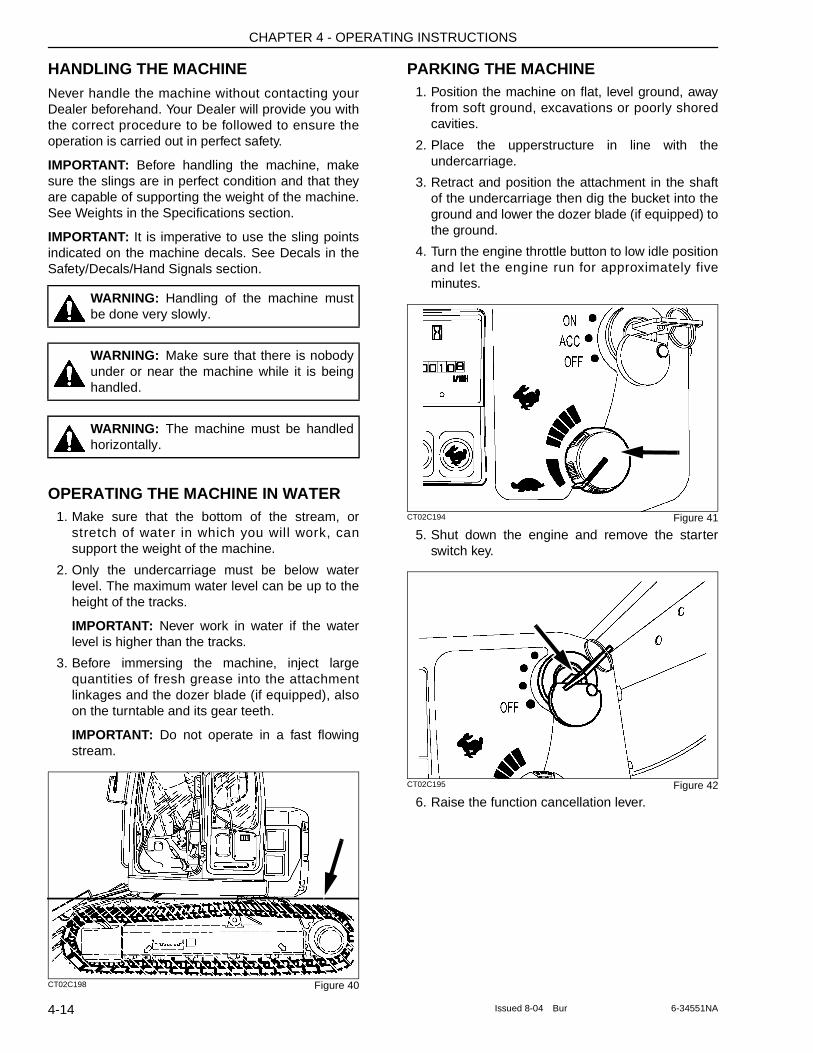
CHAPTER 4 - OPERATING INSTRUCTIONS
HANDLING THE MACHINENever handle the machine without contacting your Dealer beforehand. Your Dealer will provide you with the correct procedure to be followed to ensure the operation is carried out in perfect safety.
IMPORTANT: Before handling the machine, make sure the slings are in perfect condition and that they are capable of supporting the weight of the machine. See Weights in the Specifications section.
IMPORTANT: It is imperative to use the sling points indicated on the machine decals. See Decals in the Safety/Decals/Hand Signals section.
OPERATING THE MACHINE IN WATER1. Make sure that the bottom of the stream, or
stretch of water in which you will work, can support the weight of the machine.
2. Only the undercarriage must be below water level. The maximum water level can be up to the height of the tracks.
IMPORTANT: Never work in water if the water level is higher than the tracks.
3. Before immersing the machine, inject large quantities of fresh grease into the attachment linkages and the dozer blade (if equipped), also on the turntable and its gear teeth.
IMPORTANT: Do not operate in a fast flowing stream.
CT02C198 Figure 40
PARKING THE MACHINE1. Position the machine on flat, level ground, away
from soft ground, excavations or poorly shored cavities.
2. Place the upperstructure in line with the undercarriage.
3. Retract and position the attachment in the shaft of the undercarriage then dig the bucket into the ground and lower the dozer blade (if equipped) to the ground.
4. Turn the engine throttle button to low idle position and let the engine run for approximately five minutes.
CT02C194 Figure 41
5. Shut down the engine and remove the starter switch key.
CT02C195 Figure 42
6. Raise the function cancellation lever.
WARNING: Handling of the machine must be done very slowly.
WARNING: Make sure that there is nobody under or near the machine while it is being handled.
WARNING: The machine must be handled horizontally.
4-14 Issued 8-04 Bur 6-34551NA
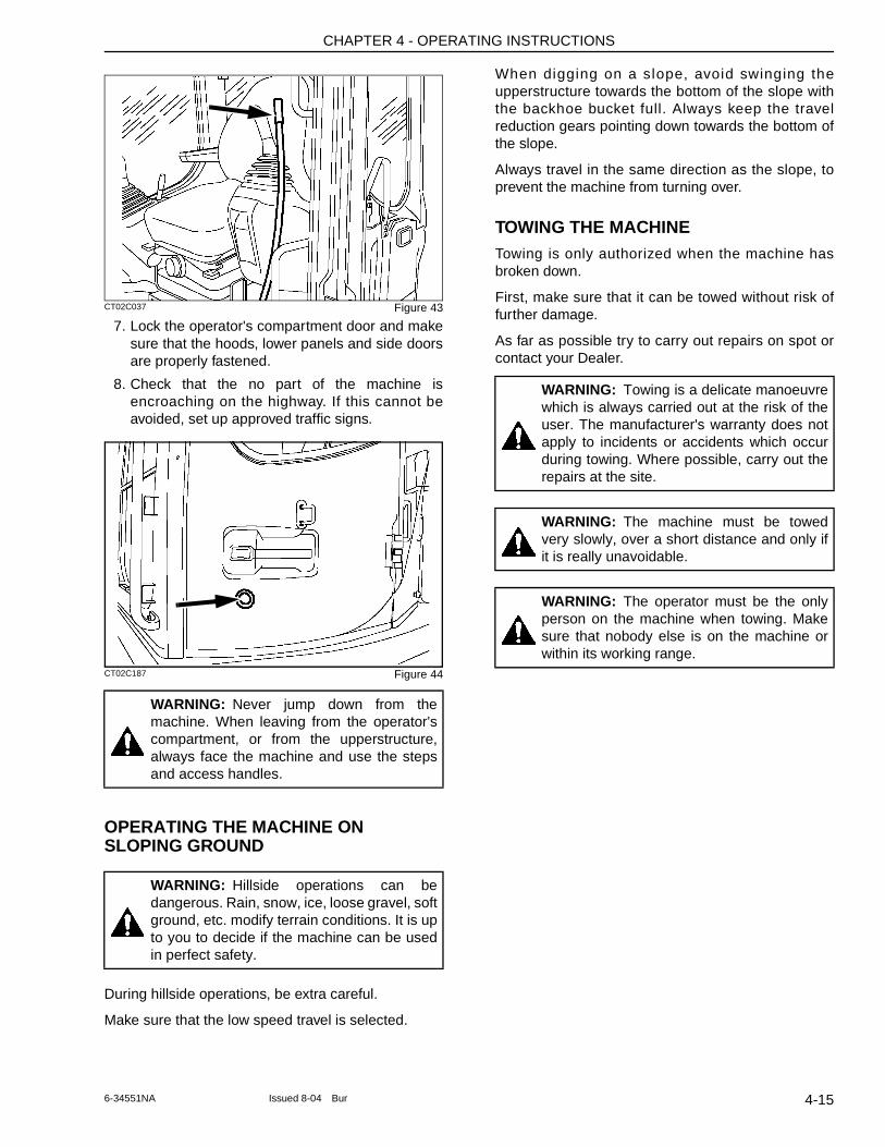
CHAPTER 4 - OPERATING INSTRUCTIONS
CT02C037 Figure 43
7. Lock the operator's compartment door and make sure that the hoods, lower panels and side doors are properly fastened.
8. Check that the no part of the machine is encroaching on the highway. If this cannot be avoided, set up approved traffic signs.
CT02C187 Figure 44
OPERATING THE MACHINE ON SLOPING GROUND
During hillside operations, be extra careful.
Make sure that the low speed travel is selected.
When digging on a slope, avoid swinging the upperstructure towards the bottom of the slope with the backhoe bucket full. Always keep the travel reduction gears pointing down towards the bottom of the slope.
Always travel in the same direction as the slope, to prevent the machine from turning over.
TOWING THE MACHINETowing is only authorized when the machine has broken down.
First, make sure that it can be towed without risk of further damage.
As far as possible try to carry out repairs on spot or contact your Dealer.
WARNING: Never jump down from the machine. When leaving from the operator's compartment, or from the upperstructure, always face the machine and use the steps and access handles.
WARNING: Hillside operations can be dangerous. Rain, snow, ice, loose gravel, soft ground, etc. modify terrain conditions. It is up to you to decide if the machine can be used in perfect safety.
WARNING: Towing is a delicate manoeuvre which is always carried out at the risk of the user. The manufacturer's warranty does not apply to incidents or accidents which occur during towing. Where possible, carry out the repairs at the site.
WARNING: The machine must be towed very slowly, over a short distance and only if it is really unavoidable.
WARNING: The operator must be the only person on the machine when towing. Make sure that nobody else is on the machine or within its working range.
4-156-34551NA Issued 8-04 Bur
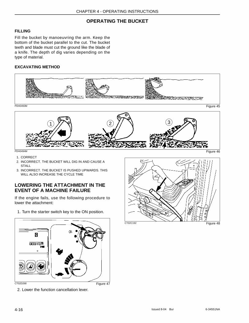
CHAPTER 4 - OPERATING INSTRUCTIONS
OPERATING THE BUCKET
FILLING
Fill the bucket by manoeuvring the arm. Keep the bottom of the bucket parallel to the cut. The bucket teeth and blade must cut the ground like the blade of a knife. The depth of dig varies depending on the type of material.
EXCAVATING METHOD
PDH0493M Figure 45
PDH0494M Figure 46
1. CORRECT2. INCORRECT. THE BUCKET WILL DIG IN AND CAUSE A
STALL3. INCORRECT. THE BUCKET IS PUSHED UPWARDS. THIS
WILL ALSO INCREASE THE CYCLE TIME
LOWERING THE ATTACHMENT IN THE EVENT OF A MACHINE FAILUREIf the engine fails, use the following procedure to lower the attachment:
1. Turn the starter switch key to the ON position.
CT02D268 Figure 47
2. Lower the function cancellation lever.
CT02C192 Figure 48
321
4-16 Issued 8-04 Bur 6-34551NA
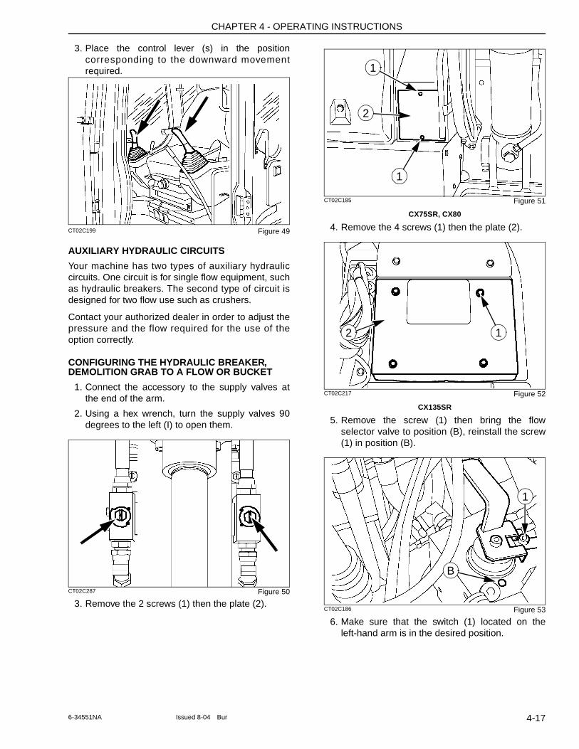
CHAPTER 4 - OPERATING INSTRUCTIONS
3. Place the control lever (s) in the position corresponding to the downward movement required.
CT02C199 Figure 49
AUXILIARY HYDRAULIC CIRCUITS
Your machine has two types of auxiliary hydraulic circuits. One circuit is for single flow equipment, such as hydraulic breakers. The second type of circuit is designed for two flow use such as crushers.
Contact your authorized dealer in order to adjust the pressure and the flow required for the use of the option correctly.
CONFIGURING THE HYDRAULIC BREAKER, DEMOLITION GRAB TO A FLOW OR BUCKET
1. Connect the accessory to the supply valves at the end of the arm.
2. Using a hex wrench, turn the supply valves 90 degrees to the left (I) to open them.
CT02C287 Figure 50
3. Remove the 2 screws (1) then the plate (2).
CT02C185 Figure 51
CX75SR, CX80
4. Remove the 4 screws (1) then the plate (2).
CT02C217 Figure 52
CX135SR
5. Remove the screw (1) then bring the flow selector valve to position (B), reinstall the screw (1) in position (B).
CT02C186 Figure 53
6. Make sure that the switch (1) located on the left-hand arm is in the desired position.
1
2
1
2 1
1
B
4-176-34551NA Issued 8-04 Bur
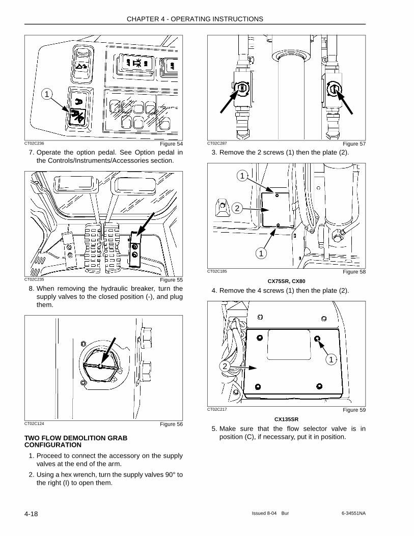
CHAPTER 4 - OPERATING INSTRUCTIONS
CT02C236 Figure 54
7. Operate the option pedal. See Option pedal in the Controls/Instruments/Accessories section.
CT02C235 Figure 55
8. When removing the hydraulic breaker, turn the supply valves to the closed position (-), and plug them.
CT02C124 Figure 56
TWO FLOW DEMOLITION GRAB CONFIGURATION
1. Proceed to connect the accessory on the supply valves at the end of the arm.
2. Using a hex wrench, turn the supply valves 90° to the right (I) to open them.
CT02C287 Figure 57
3. Remove the 2 screws (1) then the plate (2).
CT02C185 Figure 58
CX75SR, CX80
4. Remove the 4 screws (1) then the plate (2).
CT02C217 Figure 59
CX135SR
5. Make sure that the flow selector valve is in position (C), if necessary, put it in position.
1
1
2
1
12
4-18 Issued 8-04 Bur 6-34551NA
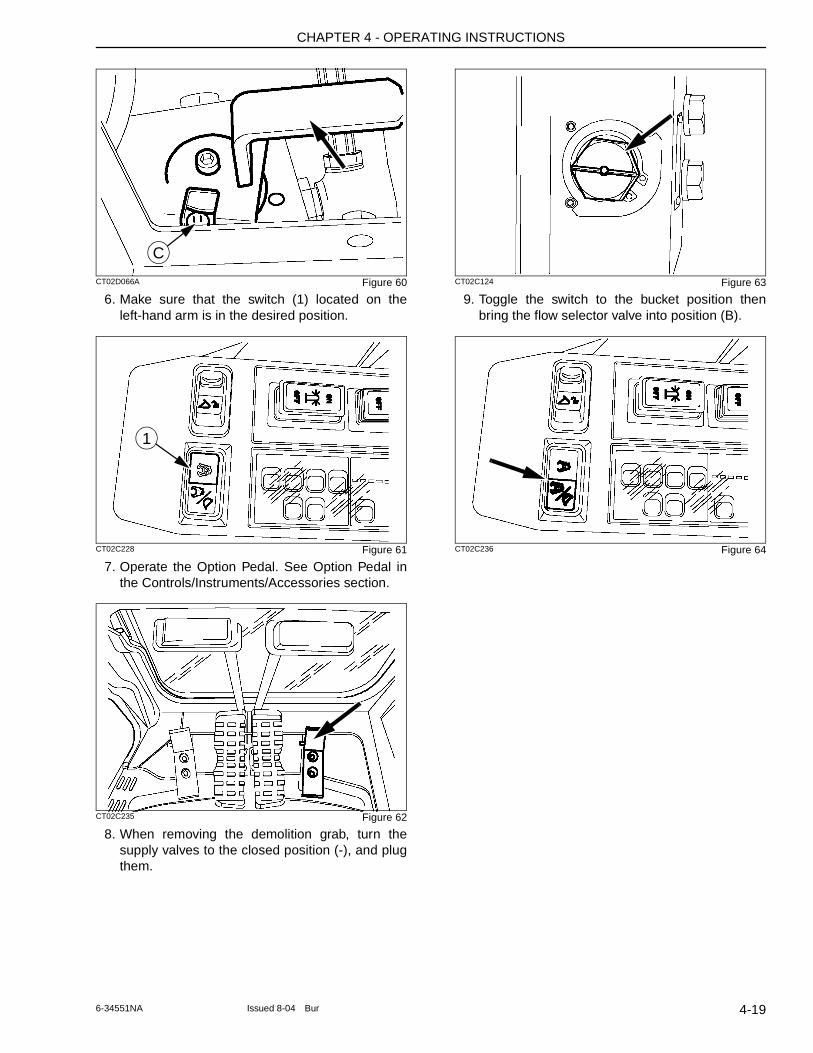
CHAPTER 4 - OPERATING INSTRUCTIONS
CT02D066A Figure 60
6. Make sure that the switch (1) located on the left-hand arm is in the desired position.
CT02C228 Figure 61
7. Operate the Option Pedal. See Option Pedal in the Controls/Instruments/Accessories section.
CT02C235 Figure 62
8. When removing the demolition grab, turn the supply valves to the closed position (-), and plug them.
CT02C124 Figure 63
9. Toggle the switch to the bucket position then bring the flow selector valve into position (B).
CT02C236 Figure 64
C
1
4-196-34551NA Issued 8-04 Bur
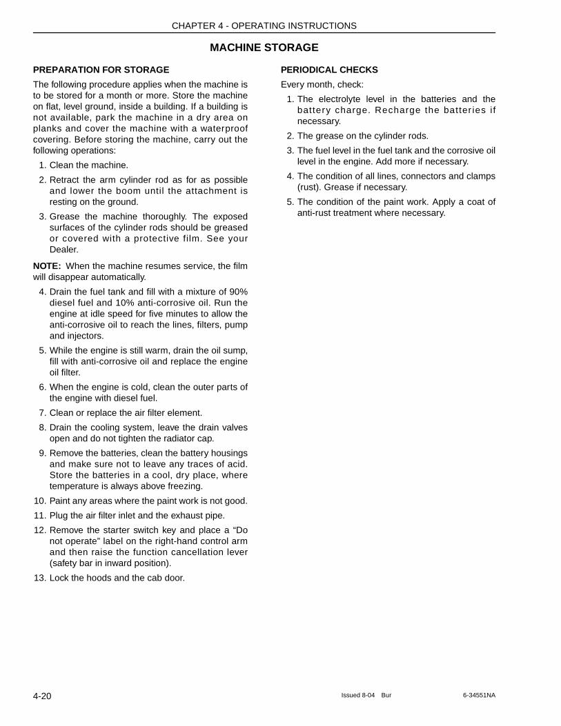
CHAPTER 4 - OPERATING INSTRUCTIONS
MACHINE STORAGE
PREPARATION FOR STORAGE
The following procedure applies when the machine is to be stored for a month or more. Store the machine on flat, level ground, inside a building. If a building is not available, park the machine in a dry area on planks and cover the machine with a waterproof covering. Before storing the machine, carry out the following operations:
1. Clean the machine.
2. Retract the arm cylinder rod as for as possible and lower the boom until the attachment is resting on the ground.
3. Grease the machine thoroughly. The exposed surfaces of the cylinder rods should be greased or covered with a protective film. See your Dealer.
NOTE: When the machine resumes service, the film will disappear automatically.
4. Drain the fuel tank and fill with a mixture of 90% diesel fuel and 10% anti-corrosive oil. Run the engine at idle speed for five minutes to allow the anti-corrosive oil to reach the lines, filters, pump and injectors.
5. While the engine is still warm, drain the oil sump, fill with anti-corrosive oil and replace the engine oil filter.
6. When the engine is cold, clean the outer parts of the engine with diesel fuel.
7. Clean or replace the air filter element.
8. Drain the cooling system, leave the drain valves open and do not tighten the radiator cap.
9. Remove the batteries, clean the battery housings and make sure not to leave any traces of acid. Store the batteries in a cool, dry place, where temperature is always above freezing.
10. Paint any areas where the paint work is not good.
11. Plug the air filter inlet and the exhaust pipe.
12. Remove the starter switch key and place a “Do not operate” label on the right-hand control arm and then raise the function cancellation lever (safety bar in inward position).
13. Lock the hoods and the cab door.
PERIODICAL CHECKS
Every month, check:
1. The electrolyte level in the batteries and the battery charge. Recharge the batter ies i f necessary.
2. The grease on the cylinder rods.
3. The fuel level in the fuel tank and the corrosive oil level in the engine. Add more if necessary.
4. The condition of all lines, connectors and clamps (rust). Grease if necessary.
5. The condition of the paint work. Apply a coat of anti-rust treatment where necessary.
4-20 Issued 8-04 Bur 6-34551NA
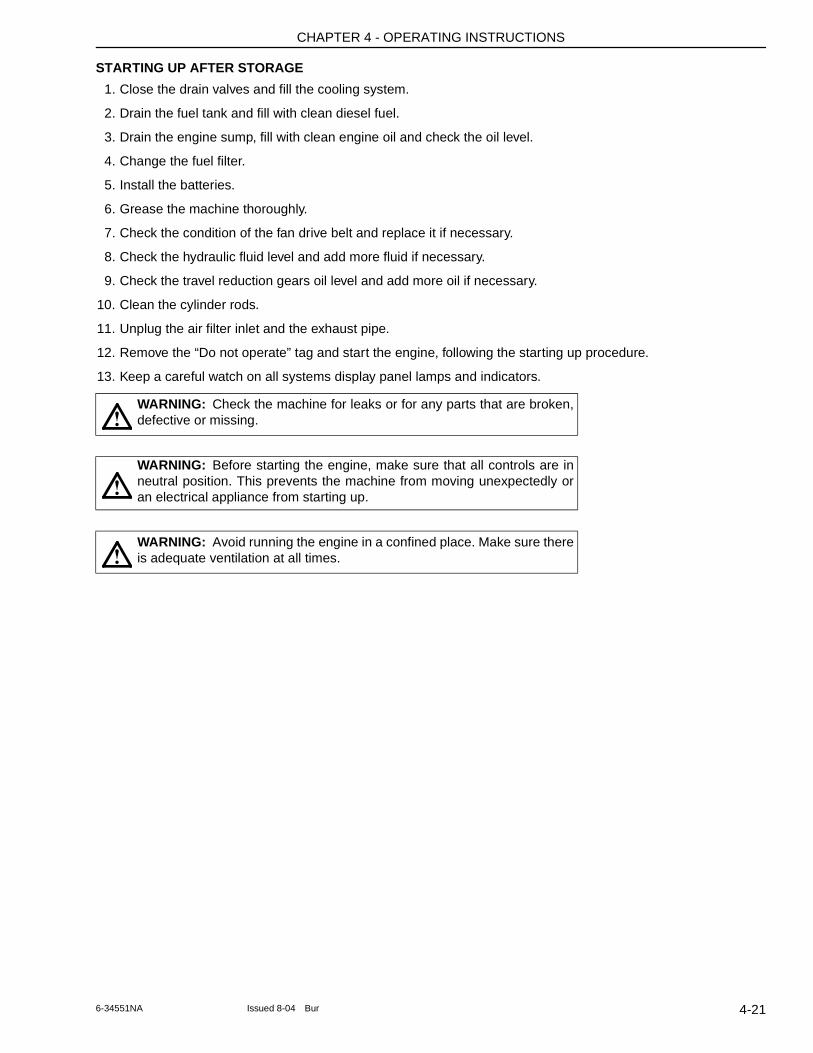
CHAPTER 4 - OPERATING INSTRUCTIONS
STARTING UP AFTER STORAGE
1. Close the drain valves and fill the cooling system.
2. Drain the fuel tank and fill with clean diesel fuel.
3. Drain the engine sump, fill with clean engine oil and check the oil level.
4. Change the fuel filter.
5. Install the batteries.
6. Grease the machine thoroughly.
7. Check the condition of the fan drive belt and replace it if necessary.
8. Check the hydraulic fluid level and add more fluid if necessary.
9. Check the travel reduction gears oil level and add more oil if necessary.
10. Clean the cylinder rods.
11. Unplug the air filter inlet and the exhaust pipe.
12. Remove the “Do not operate” tag and start the engine, following the starting up procedure.
13. Keep a careful watch on all systems display panel lamps and indicators.
WARNING: Check the machine for leaks or for any parts that are broken, defective or missing.
WARNING: Before starting the engine, make sure that all controls are in neutral position. This prevents the machine from moving unexpectedly or an electrical appliance from starting up.
WARNING: Avoid running the engine in a confined place. Make sure there is adequate ventilation at all times.
!
!
!
4-216-34551NA Issued 8-04 Bur

CHAPTER 4 - OPERATING INSTRUCTIONS
NOTES
4-22 Issued 8-04 Bur 6-34551NA
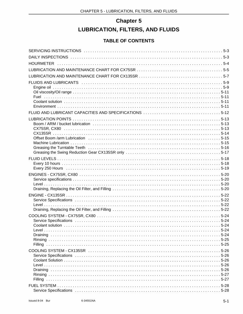
CHAPTER 5 - LUBRICATION, FILTERS, AND FLUIDS
Chapter 5
LUBRICATION, FILTERS, AND FLUIDS
TABLE OF CONTENTS
SERVICING INSTRUCTIONS . . . . . . . . . . . . . . . . . . . . . . . . . . . . . . . . . . . . . . . . . . . . . . . . . . . . . . . . . . . . . . . 5-3
DAILY INSPECTIONS . . . . . . . . . . . . . . . . . . . . . . . . . . . . . . . . . . . . . . . . . . . . . . . . . . . . . . . . . . . . . . . . . . . . . 5-3
HOURMETER . . . . . . . . . . . . . . . . . . . . . . . . . . . . . . . . . . . . . . . . . . . . . . . . . . . . . . . . . . . . . . . . . . . . . . . . . . . 5-4
LUBRICATION AND MAINTENANCE CHART FOR CX75SR . . . . . . . . . . . . . . . . . . . . . . . . . . . . . . . . . . . . . . . 5-5
LUBRICATION AND MAINTENANCE CHART FOR CX135SR . . . . . . . . . . . . . . . . . . . . . . . . . . . . . . . . . . . . . . 5-7
FLUIDS AND LUBRICANTS . . . . . . . . . . . . . . . . . . . . . . . . . . . . . . . . . . . . . . . . . . . . . . . . . . . . . . . . . . . . . . . . 5-9Engine oil . . . . . . . . . . . . . . . . . . . . . . . . . . . . . . . . . . . . . . . . . . . . . . . . . . . . . . . . . . . . . . . . . . . . . . . . . . . . . 5-9Oil viscosity/Oil range . . . . . . . . . . . . . . . . . . . . . . . . . . . . . . . . . . . . . . . . . . . . . . . . . . . . . . . . . . . . . . . . . . . 5-11Fuel . . . . . . . . . . . . . . . . . . . . . . . . . . . . . . . . . . . . . . . . . . . . . . . . . . . . . . . . . . . . . . . . . . . . . . . . . . . . . . . . 5-11Coolant solution . . . . . . . . . . . . . . . . . . . . . . . . . . . . . . . . . . . . . . . . . . . . . . . . . . . . . . . . . . . . . . . . . . . . . . . 5-11Environment . . . . . . . . . . . . . . . . . . . . . . . . . . . . . . . . . . . . . . . . . . . . . . . . . . . . . . . . . . . . . . . . . . . . . . . . . . 5-11
FLUID AND LUBRICANT CAPACITIES AND SPECIFICATIONS . . . . . . . . . . . . . . . . . . . . . . . . . . . . . . . . . . . 5-12
LUBRICATION POINTS . . . . . . . . . . . . . . . . . . . . . . . . . . . . . . . . . . . . . . . . . . . . . . . . . . . . . . . . . . . . . . . . . . . 5-13Boom / ARM / bucket lubrication . . . . . . . . . . . . . . . . . . . . . . . . . . . . . . . . . . . . . . . . . . . . . . . . . . . . . . . . . . 5-13CX75SR, CX80 . . . . . . . . . . . . . . . . . . . . . . . . . . . . . . . . . . . . . . . . . . . . . . . . . . . . . . . . . . . . . . . . . . . . . . . 5-13CX135SR . . . . . . . . . . . . . . . . . . . . . . . . . . . . . . . . . . . . . . . . . . . . . . . . . . . . . . . . . . . . . . . . . . . . . . . . . . . . 5-14Offset Boom /arm Lubrication . . . . . . . . . . . . . . . . . . . . . . . . . . . . . . . . . . . . . . . . . . . . . . . . . . . . . . . . . . . . 5-15Machine Lubrication . . . . . . . . . . . . . . . . . . . . . . . . . . . . . . . . . . . . . . . . . . . . . . . . . . . . . . . . . . . . . . . . . . . . 5-15Greasing the Turntable Teeth . . . . . . . . . . . . . . . . . . . . . . . . . . . . . . . . . . . . . . . . . . . . . . . . . . . . . . . . . . . . 5-16Greasing the Swing Reduction Gear CX135SR only . . . . . . . . . . . . . . . . . . . . . . . . . . . . . . . . . . . . . . . . . . . 5-17
FLUID LEVELS . . . . . . . . . . . . . . . . . . . . . . . . . . . . . . . . . . . . . . . . . . . . . . . . . . . . . . . . . . . . . . . . . . . . . . . . . . 5-18Every 10 hours . . . . . . . . . . . . . . . . . . . . . . . . . . . . . . . . . . . . . . . . . . . . . . . . . . . . . . . . . . . . . . . . . . . . . . . . 5-18Every 250 Hours . . . . . . . . . . . . . . . . . . . . . . . . . . . . . . . . . . . . . . . . . . . . . . . . . . . . . . . . . . . . . . . . . . . . . . 5-19
ENGINES - CX75SR, CX80 . . . . . . . . . . . . . . . . . . . . . . . . . . . . . . . . . . . . . . . . . . . . . . . . . . . . . . . . . . . . . . . . 5-20Service specifications . . . . . . . . . . . . . . . . . . . . . . . . . . . . . . . . . . . . . . . . . . . . . . . . . . . . . . . . . . . . . . . . . . . 5-20Level . . . . . . . . . . . . . . . . . . . . . . . . . . . . . . . . . . . . . . . . . . . . . . . . . . . . . . . . . . . . . . . . . . . . . . . . . . . . . . . . 5-20Draining, Replacing the Oil Filter, and Filling . . . . . . . . . . . . . . . . . . . . . . . . . . . . . . . . . . . . . . . . . . . . . . . . . 5-20
ENGINE - CX135SR . . . . . . . . . . . . . . . . . . . . . . . . . . . . . . . . . . . . . . . . . . . . . . . . . . . . . . . . . . . . . . . . . . . . . . 5-22Service Specifications . . . . . . . . . . . . . . . . . . . . . . . . . . . . . . . . . . . . . . . . . . . . . . . . . . . . . . . . . . . . . . . . . . 5-22Level . . . . . . . . . . . . . . . . . . . . . . . . . . . . . . . . . . . . . . . . . . . . . . . . . . . . . . . . . . . . . . . . . . . . . . . . . . . . . . . . 5-22Draining, Replacing the Oil Filter, and Filling . . . . . . . . . . . . . . . . . . . . . . . . . . . . . . . . . . . . . . . . . . . . . . . . . 5-22
COOLING SYSTEM - CX75SR, CX80 . . . . . . . . . . . . . . . . . . . . . . . . . . . . . . . . . . . . . . . . . . . . . . . . . . . . . . . . 5-24Service Specifications . . . . . . . . . . . . . . . . . . . . . . . . . . . . . . . . . . . . . . . . . . . . . . . . . . . . . . . . . . . . . . . . . . 5-24Coolant solution . . . . . . . . . . . . . . . . . . . . . . . . . . . . . . . . . . . . . . . . . . . . . . . . . . . . . . . . . . . . . . . . . . . . . . . 5-24Level . . . . . . . . . . . . . . . . . . . . . . . . . . . . . . . . . . . . . . . . . . . . . . . . . . . . . . . . . . . . . . . . . . . . . . . . . . . . . . . . 5-24Draining . . . . . . . . . . . . . . . . . . . . . . . . . . . . . . . . . . . . . . . . . . . . . . . . . . . . . . . . . . . . . . . . . . . . . . . . . . . . . 5-24Rinsing . . . . . . . . . . . . . . . . . . . . . . . . . . . . . . . . . . . . . . . . . . . . . . . . . . . . . . . . . . . . . . . . . . . . . . . . . . . . . . 5-25Filling . . . . . . . . . . . . . . . . . . . . . . . . . . . . . . . . . . . . . . . . . . . . . . . . . . . . . . . . . . . . . . . . . . . . . . . . . . . . . . . 5-25
COOLING SYSTEM - CX135SR . . . . . . . . . . . . . . . . . . . . . . . . . . . . . . . . . . . . . . . . . . . . . . . . . . . . . . . . . . . . 5-26Service Specifications . . . . . . . . . . . . . . . . . . . . . . . . . . . . . . . . . . . . . . . . . . . . . . . . . . . . . . . . . . . . . . . . . . 5-26Coolant Solution . . . . . . . . . . . . . . . . . . . . . . . . . . . . . . . . . . . . . . . . . . . . . . . . . . . . . . . . . . . . . . . . . . . . . . . 5-26Level . . . . . . . . . . . . . . . . . . . . . . . . . . . . . . . . . . . . . . . . . . . . . . . . . . . . . . . . . . . . . . . . . . . . . . . . . . . . . . . . 5-26Draining . . . . . . . . . . . . . . . . . . . . . . . . . . . . . . . . . . . . . . . . . . . . . . . . . . . . . . . . . . . . . . . . . . . . . . . . . . . . . 5-26Rinsing . . . . . . . . . . . . . . . . . . . . . . . . . . . . . . . . . . . . . . . . . . . . . . . . . . . . . . . . . . . . . . . . . . . . . . . . . . . . . . 5-27Filling . . . . . . . . . . . . . . . . . . . . . . . . . . . . . . . . . . . . . . . . . . . . . . . . . . . . . . . . . . . . . . . . . . . . . . . . . . . . . . . 5-27
FUEL SYSTEM . . . . . . . . . . . . . . . . . . . . . . . . . . . . . . . . . . . . . . . . . . . . . . . . . . . . . . . . . . . . . . . . . . . . . . . . . . 5-28Service Specifications . . . . . . . . . . . . . . . . . . . . . . . . . . . . . . . . . . . . . . . . . . . . . . . . . . . . . . . . . . . . . . . . . . 5-28
5-1Issued 8-04 Bur 6-34551NA
CHAPTER 5 - LUBRICATION, FILTERS, AND FLUIDS
Fuel System Air Bleed . . . . . . . . . . . . . . . . . . . . . . . . . . . . . . . . . . . . . . . . . . . . . . . . . . . . . . . . . . . . . . . . . . .5-28Draining the Fuel Tank . . . . . . . . . . . . . . . . . . . . . . . . . . . . . . . . . . . . . . . . . . . . . . . . . . . . . . . . . . . . . . . . . .5-28Bleeding the Water Separator . . . . . . . . . . . . . . . . . . . . . . . . . . . . . . . . . . . . . . . . . . . . . . . . . . . . . . . . . . . . .5-29Cleaning the Water Separator Filter . . . . . . . . . . . . . . . . . . . . . . . . . . . . . . . . . . . . . . . . . . . . . . . . . . . . . . . .5-29Replacing the Fuel Filter . . . . . . . . . . . . . . . . . . . . . . . . . . . . . . . . . . . . . . . . . . . . . . . . . . . . . . . . . . . . . . . . .5-30Filling the Fuel Tank . . . . . . . . . . . . . . . . . . . . . . . . . . . . . . . . . . . . . . . . . . . . . . . . . . . . . . . . . . . . . . . . . . . .5-30
RELEASING PRESSURE IN THE HYDRAULIC SYSTEM . . . . . . . . . . . . . . . . . . . . . . . . . . . . . . . . . . . . . . . . 5-32
HYDRAULIC SYSTEM . . . . . . . . . . . . . . . . . . . . . . . . . . . . . . . . . . . . . . . . . . . . . . . . . . . . . . . . . . . . . . . . . . . 5-33Service Specifications . . . . . . . . . . . . . . . . . . . . . . . . . . . . . . . . . . . . . . . . . . . . . . . . . . . . . . . . . . . . . . . . . . .5-33Level in the Reservoir . . . . . . . . . . . . . . . . . . . . . . . . . . . . . . . . . . . . . . . . . . . . . . . . . . . . . . . . . . . . . . . . . . .5-34Accessing the Hydraulic Reservoir - CX75SR, CX80 . . . . . . . . . . . . . . . . . . . . . . . . . . . . . . . . . . . . . . . . . . .5-34Filling the Hydraulic Reservoir - CX75SR, CX80 . . . . . . . . . . . . . . . . . . . . . . . . . . . . . . . . . . . . . . . . . . . . . .5-34Filling the Hydraulic Reservoir - CX135SR . . . . . . . . . . . . . . . . . . . . . . . . . . . . . . . . . . . . . . . . . . . . . . . . . . .5-35Pilot Filter Replacement . . . . . . . . . . . . . . . . . . . . . . . . . . . . . . . . . . . . . . . . . . . . . . . . . . . . . . . . . . . . . . . . .5-35Cleaning and Replacement of the Inlet Filter . . . . . . . . . . . . . . . . . . . . . . . . . . . . . . . . . . . . . . . . . . . . . . . . .5-36Return Filter Replacement . . . . . . . . . . . . . . . . . . . . . . . . . . . . . . . . . . . . . . . . . . . . . . . . . . . . . . . . . . . . . . .5-37Ultra Clean Filter Replacement . . . . . . . . . . . . . . . . . . . . . . . . . . . . . . . . . . . . . . . . . . . . . . . . . . . . . . . . . . . .5-37Replacing the Reservoir Breather . . . . . . . . . . . . . . . . . . . . . . . . . . . . . . . . . . . . . . . . . . . . . . . . . . . . . . . . . .5-38Replacing the Hydraulic Fluid . . . . . . . . . . . . . . . . . . . . . . . . . . . . . . . . . . . . . . . . . . . . . . . . . . . . . . . . . . . . .5-39Bleeding Air from the Hydraulic Components . . . . . . . . . . . . . . . . . . . . . . . . . . . . . . . . . . . . . . . . . . . . . . . . .5-39Hydraulic Breaker (Optional) - Replacing Hydraulic Fluid and Filters . . . . . . . . . . . . . . . . . . . . . . . . . . . . . . .5-41
AIR FILTER . . . . . . . . . . . . . . . . . . . . . . . . . . . . . . . . . . . . . . . . . . . . . . . . . . . . . . . . . . . . . . . . . . . . . . . . . . . . 5-43Service Specifications . . . . . . . . . . . . . . . . . . . . . . . . . . . . . . . . . . . . . . . . . . . . . . . . . . . . . . . . . . . . . . . . . . .5-43Inspection . . . . . . . . . . . . . . . . . . . . . . . . . . . . . . . . . . . . . . . . . . . . . . . . . . . . . . . . . . . . . . . . . . . . . . . . . . . .5-43Air Filter Restriction Indicator . . . . . . . . . . . . . . . . . . . . . . . . . . . . . . . . . . . . . . . . . . . . . . . . . . . . . . . . . . . . .5-43Removing the Elements . . . . . . . . . . . . . . . . . . . . . . . . . . . . . . . . . . . . . . . . . . . . . . . . . . . . . . . . . . . . . . . . .5-43Cleaning the Primary Element . . . . . . . . . . . . . . . . . . . . . . . . . . . . . . . . . . . . . . . . . . . . . . . . . . . . . . . . . . . .5-44Cleaning the Element . . . . . . . . . . . . . . . . . . . . . . . . . . . . . . . . . . . . . . . . . . . . . . . . . . . . . . . . . . . . . . . . . . .5-44Inspecting the Element . . . . . . . . . . . . . . . . . . . . . . . . . . . . . . . . . . . . . . . . . . . . . . . . . . . . . . . . . . . . . . . . . .5-44Cleaning the Element Housing . . . . . . . . . . . . . . . . . . . . . . . . . . . . . . . . . . . . . . . . . . . . . . . . . . . . . . . . . . . .5-44Installing the Elements . . . . . . . . . . . . . . . . . . . . . . . . . . . . . . . . . . . . . . . . . . . . . . . . . . . . . . . . . . . . . . . . . .5-45
SWING REDUCTION GEAR - CX135SR . . . . . . . . . . . . . . . . . . . . . . . . . . . . . . . . . . . . . . . . . . . . . . . . . . . . . 5-46Service Specifications . . . . . . . . . . . . . . . . . . . . . . . . . . . . . . . . . . . . . . . . . . . . . . . . . . . . . . . . . . . . . . . . . . .5-46Level . . . . . . . . . . . . . . . . . . . . . . . . . . . . . . . . . . . . . . . . . . . . . . . . . . . . . . . . . . . . . . . . . . . . . . . . . . . . . . . .5-46Draining and Refilling . . . . . . . . . . . . . . . . . . . . . . . . . . . . . . . . . . . . . . . . . . . . . . . . . . . . . . . . . . . . . . . . . . .5-46
TRAVEL REDUCTION GEARS - CX75SR, CX80 . . . . . . . . . . . . . . . . . . . . . . . . . . . . . . . . . . . . . . . . . . . . . . 5-48Service Specifications . . . . . . . . . . . . . . . . . . . . . . . . . . . . . . . . . . . . . . . . . . . . . . . . . . . . . . . . . . . . . . . . . . .5-48Level . . . . . . . . . . . . . . . . . . . . . . . . . . . . . . . . . . . . . . . . . . . . . . . . . . . . . . . . . . . . . . . . . . . . . . . . . . . . . . . .5-48Draining and Refilling . . . . . . . . . . . . . . . . . . . . . . . . . . . . . . . . . . . . . . . . . . . . . . . . . . . . . . . . . . . . . . . . . . .5-48
TRAVEL REDUCTION GEARS - CX135SR . . . . . . . . . . . . . . . . . . . . . . . . . . . . . . . . . . . . . . . . . . . . . . . . . . . 5-49Service Specifications . . . . . . . . . . . . . . . . . . . . . . . . . . . . . . . . . . . . . . . . . . . . . . . . . . . . . . . . . . . . . . . . . . .5-49Level . . . . . . . . . . . . . . . . . . . . . . . . . . . . . . . . . . . . . . . . . . . . . . . . . . . . . . . . . . . . . . . . . . . . . . . . . . . . . . . .5-49Draining and Refilling . . . . . . . . . . . . . . . . . . . . . . . . . . . . . . . . . . . . . . . . . . . . . . . . . . . . . . . . . . . . . . . . . . .5-49
5-2 Issued 8-04 Bur 6-34551NA
CHAPTER 5 - LUBRICATION, FILTERS, AND FLUIDS
SERVICING INSTRUCTIONSRespect the maintenance intervals by checking the hourmeter every day. Before starting maintenance, park the machine on flat, firm ground, away from any obstacles, with the arm retracted and the bucket on the ground. Unless otherwise spec i f ied , a l l maintenance operations must be carried out with the engine stopped, and the key removed from the starter switch. It is preferable to wait for all circuits to cool down before starting work.
Clean the grease fittings before lubrication. Clean around plugs and filler holes before adding fluid. No dust or dirt must enter the components or the circuits. Wear suitable clothing and remember to use the necessary safety equipment.
When carrying out service work on the machine, place a Do Not Operate tag on the instrument panel. Never climb down from the operator's compartment leaving the engine running.
Any modification to this machine without prior authorization could cause serious injury. Do not make any modifications without authorization. Consult your Dealer.
IMPORTANT: If you use your machine in particularly harsh conditions (dusty or corrosive atmosphere, etc.), the servicing intervals should be reduced accordingly.
IMPORTANT: Take particular care to replace all filters regularly. Clean filters mean longer engine running life.
IMPORTANT: Oil and fluid should not be thrown on the ground. They must be stored and removed by a company which is responsible for their recycling or their disposal.
SERVICE SPECIFICATIONS
Intervals between overhauls are much more frequent for the following applications: construction of tunnels using a hydraulic breaker, scale stripping, foundry cleaning, operation under water etc. For special applications consult your Dealer.
DAILY INSPECTIONSEvery day, before starting work, it is necessary to inspect the machine and service cer tain of its components.
GENERAL REMARKS
Check for water or oil leaks.
Check that all screws and nuts are correctly tightened.
Wipe o f f any dus t (eng ine, opera to r ' s compartment, etc.).
Check for damage.
ENGINE
Check the o i l level and change the o i l i f necessary.
Check the coolant level.
Check for clogging or damage to the radiator.
Check the radiator fan belt tension.
Check the air filter is clean and not restricted.
Check for water or oil leaks on the components.
Check the condition of all lines.
UPPERSTRUCTURE
Check the fuel tank level.
Check the hydraulic reservoir level.
Check that the hydraulic oil is clean.
Check for water or oil leaks on the components.
Check the condition of all lines.
Check for electrical short-circuits.
Check the battery connections are properly tightened.
Adjust the rear view mirrors.
UNDERCARRIAGE
Check the pad hardware.
Check the condition of the tracks.
WARNING: There is a risk of serious injury if maintenance or repairs are not carried out correctly. If you do not understand maintenance procedures, consult your Dealer.
WARNING: If the attachment is raised or if the machine moves without an operator, serious injury can result. Before performing any maintenance, proceed as follows:
1. Park the machine on flat, level ground.2. Lower the attachment until it is resting on
the ground.3. Lower the dozer blade (if equipped) until
it rests on the ground.4. Shut down the engine and remove the
starter key switch.5. Lock the tracks to prevent any machine
movement.
WARNING: Be sure all the service operations in this section are carried out punctually at the intervals given, in order to ensure optimum performance levels and maximum safety when using the machine.
5-36-34551NA Issued 8-04 Bur
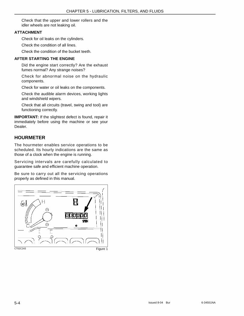
CHAPTER 5 - LUBRICATION, FILTERS, AND FLUIDS
Check that the upper and lower rollers and the idler wheels are not leaking oil.
ATTACHMENT
Check for oil leaks on the cylinders.
Check the condition of all lines.
Check the condition of the bucket teeth.
AFTER STARTING THE ENGINE
Did the engine start correctly? Are the exhaust fumes normal? Any strange noises?
Check for abnormal noise on the hydraulic components.
Check for water or oil leaks on the components.
Check the audible alarm devices, working lights and windshield wipers.
Check that all circuits (travel, swing and tool) are functioning correctly.
IMPORTANT: If the slightest defect is found, repair it immediately before using the machine or see your Dealer.
HOURMETERThe hourmeter enables service operations to be scheduled. Its hourly indications are the same as those of a clock when the engine is running.
Servicing intervals are carefully calculated to guarantee safe and efficient machine operation.
Be sure to carry out all the servicing operations properly as defined in this manual.
CT02C243 Figure 1
5-4 Issued 8-04 Bur 6-34551NA
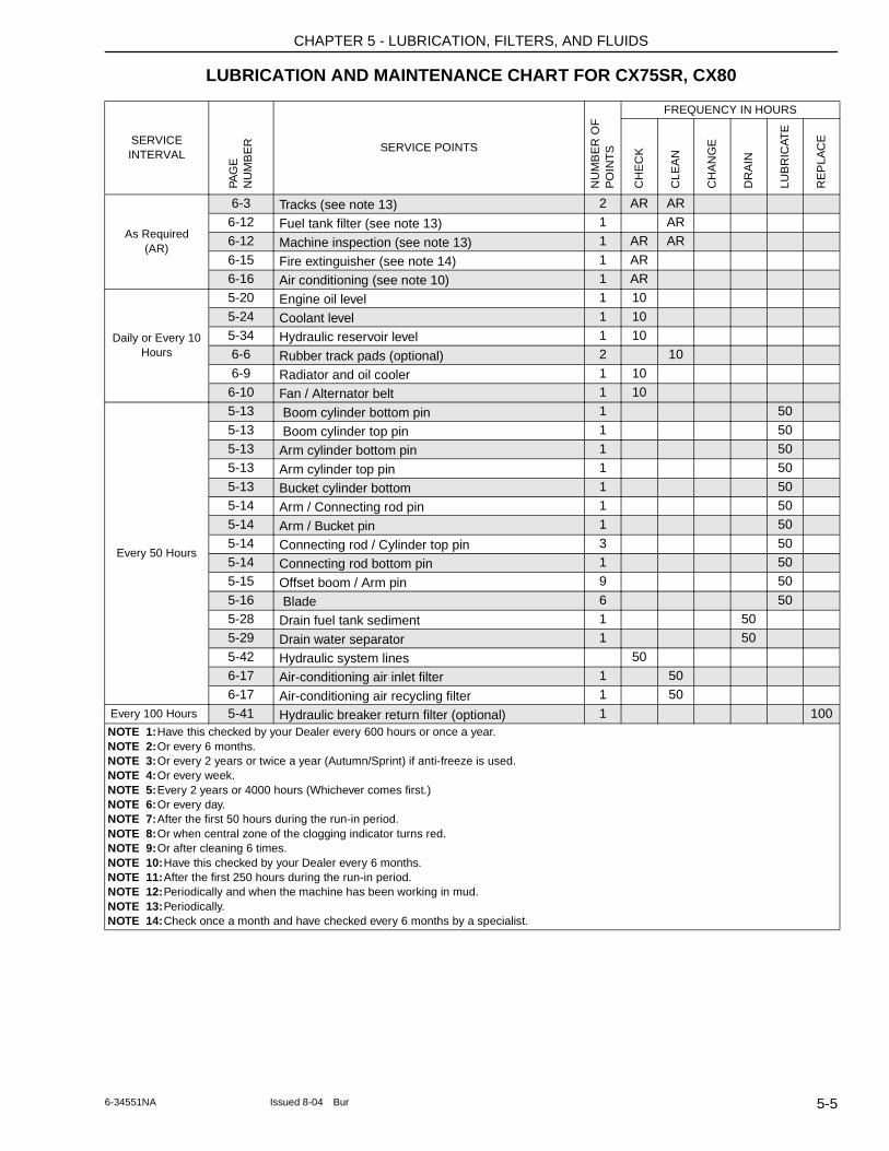
CHAPTER 5 - LUBRICATION, FILTERS, AND FLUIDS
LUBRICATION AND MAINTENANCE CHART FOR CX75SR, CX80
SERVICE INTERVAL
PAG
E
NU
MB
ER SERVICE POINTS
NU
MB
ER
OF
P
OIN
TS
FREQUENCY IN HOURS
CH
EC
K
CLE
AN
CH
AN
GE
DR
AIN
LUB
RIC
ATE
RE
PLA
CE
As Required(AR)
6-3 Tracks (see note 13) 2 AR AR6-12 Fuel tank filter (see note 13) 1 AR6-12 Machine inspection (see note 13) 1 AR AR
6-15 Fire extinguisher (see note 14) 1 AR6-16 Air conditioning (see note 10) 1 AR
Daily or Every 10 Hours
5-20 Engine oil level 1 10
5-24 Coolant level 1 105-34 Hydraulic reservoir level 1 106-6 Rubber track pads (optional) 2 10
6-9 Radiator and oil cooler 1 106-10 Fan / Alternator belt 1 10
Every 50 Hours
5-13 Boom cylinder bottom pin 1 50
5-13 Boom cylinder top pin 1 505-13 Arm cylinder bottom pin 1 505-13 Arm cylinder top pin 1 50
5-13 Bucket cylinder bottom 1 505-14 Arm / Connecting rod pin 1 505-14 Arm / Bucket pin 1 50
5-14 Connecting rod / Cylinder top pin 3 505-14 Connecting rod bottom pin 1 505-15 Offset boom / Arm pin 9 50
5-16 Blade 6 505-28 Drain fuel tank sediment 1 505-29 Drain water separator 1 50
5-42 Hydraulic system lines 506-17 Air-conditioning air inlet filter 1 506-17 Air-conditioning air recycling filter 1 50
Every 100 Hours 5-41 Hydraulic breaker return filter (optional) 1 100NOTE 1: Have this checked by your Dealer every 600 hours or once a year.NOTE 2: Or every 6 months.NOTE 3: Or every 2 years or twice a year (Autumn/Sprint) if anti-freeze is used.NOTE 4: Or every week.NOTE 5: Every 2 years or 4000 hours (Whichever comes first.)NOTE 6: Or every day.NOTE 7: After the first 50 hours during the run-in period.NOTE 8: Or when central zone of the clogging indicator turns red.NOTE 9: Or after cleaning 6 times.NOTE 10: Have this checked by your Dealer every 6 months.NOTE 11: After the first 250 hours during the run-in period.NOTE 12: Periodically and when the machine has been working in mud.NOTE 13: Periodically.NOTE 14: Check once a month and have checked every 6 months by a specialist.
5-56-34551NA Issued 8-04 Bur
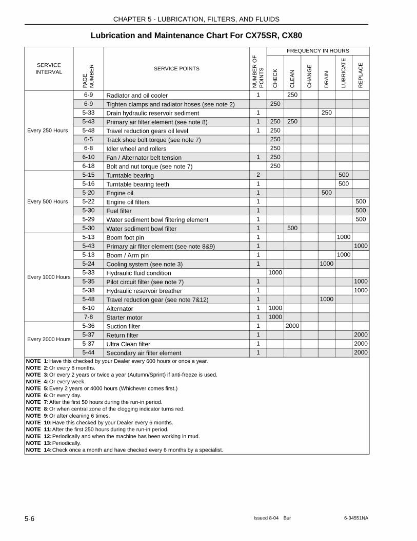
CHAPTER 5 - LUBRICATION, FILTERS, AND FLUIDS
Lubrication and Maintenance Chart For CX75SR, CX80
SERVICE INTERVAL
PAG
E
NU
MB
ER SERVICE POINTS
NU
MB
ER
OF
P
OIN
TS
FREQUENCY IN HOURS
CH
EC
K
CLE
AN
CH
AN
GE
DR
AIN
LUB
RIC
ATE
RE
PLA
CE
Every 250 Hours
6-9 Radiator and oil cooler 1 250
6-9 Tighten clamps and radiator hoses (see note 2) 2505-33 Drain hydraulic reservoir sediment 1 2505-43 Primary air filter element (see note 8) 1 250 250
5-48 Travel reduction gears oil level 1 2506-5 Track shoe bolt torque (see note 7) 2506-8 Idler wheel and rollers 250
6-10 Fan / Alternator belt tension 1 2506-18 Bolt and nut torque (see note 7) 250
Every 500 Hours
5-15 Turntable bearing 2 500
5-16 Turntable bearing teeth 1 5005-20 Engine oil 1 5005-22 Engine oil filters 1 500
5-30 Fuel filter 1 5005-29 Water sediment bowl filtering element 1 5005-30 Water sediment bowl filter 1 500
Every 1000 Hours
5-13 Boom foot pin 1 10005-43 Primary air filter element (see note 8&9) 1 1000 5-13 Boom / Arm pin 1 1000
5-24 Cooling system (see note 3) 1 1000 5-33 Hydraulic fluid condition 10005-35 Pilot circuit filter (see note 7) 1 1000
5-38 Hydraulic reservoir breather 1 10005-48 Travel reduction gear (see note 7&12) 1 1000 6-10 Alternator 1 1000
7-8 Starter motor 1 1000
Every 2000 Hours
5-36 Suction filter 1 20005-37 Return filter 1 2000
5-37 Ultra Clean filter 1 20005-44 Secondary air filter element 1 2000
NOTE 1: Have this checked by your Dealer every 600 hours or once a year.NOTE 2: Or every 6 months.NOTE 3: Or every 2 years or twice a year (Autumn/Sprint) if anti-freeze is used.NOTE 4: Or every week.NOTE 5: Every 2 years or 4000 hours (Whichever comes first.)NOTE 6: Or every day.NOTE 7: After the first 50 hours during the run-in period.NOTE 8: Or when central zone of the clogging indicator turns red.NOTE 9: Or after cleaning 6 times.NOTE 10: Have this checked by your Dealer every 6 months.NOTE 11: After the first 250 hours during the run-in period.NOTE 12: Periodically and when the machine has been working in mud.NOTE 13: Periodically.NOTE 14: Check once a month and have checked every 6 months by a specialist.
5-6 Issued 8-04 Bur 6-34551NA
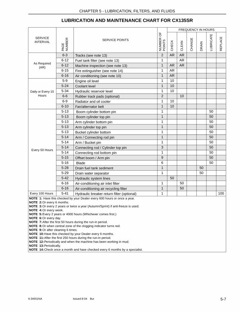
CHAPTER 5 - LUBRICATION, FILTERS, AND FLUIDS
LUBRICATION AND MAINTENANCE CHART FOR CX135SR
SERVICE INTERVAL
PAG
E
NU
MB
ER SERVICE POINTS
NU
MB
ER
OF
P
OIN
TS
FREQUENCY IN HOURS
CH
EC
K
CLE
AN
CH
AN
GE
DR
AIN
LUB
RIC
ATE
RE
PLA
CE
As Required(AR)
6-3 Tracks (see note 13) 2 AR AR6-12 Fuel tank filter (see note 13) 1 AR6-12 Machine inspection (see note 13) 1 AR AR
6-15 Fire extinguisher (see note 14) 1 AR6-16 Air conditioning (see note 10) 1 AR
Daily or Every 10 Hours
5-9 Engine oil level 1 10
5-24 Coolant level 1 105-34 Hydraulic reservoir level 1 106-6 Rubber track pads (optional) 2 10
6-9 Radiator and oil cooler 1 106-10 Fan/alternator belt 1 10
Every 50 Hours
5-13 Boom cylinder bottom pin 1 50
5-13 Boom cylinder top pin 1 505-13 Arm cylinder bottom pin 1 505-13 Arm cylinder top pin 1 50
5-13 Bucket cylinder bottom 1 505-14 Arm / Connecting rod pin 1 505-14 Arm / Bucket pin 1 50
5-14 Connecting rod / Cylinder top pin 3 505-14 Connecting rod bottom pin 1 505-15 Offset boom / Arm pin 9 50
5-16 Blade 6 505-28 Drain fuel tank sediment 1 505-29 Drain water separator 1 50
5-42 Hydraulic system lines 506-16 Air-conditioning air inlet filter 1 506-16 Air-conditioning air recycling filter 1 50
Every 100 Hours 5-41 Hydraulic breaker return filter (optional) 1 100NOTE 1: Have this checked by your Dealer every 600 hours or once a year.NOTE 2: Or every 6 months.NOTE 3: Or every 2 years or twice a year (Autumn/Sprint) if anti-freeze is used.NOTE 4: Or every week.NOTE 5: Every 2 years or 4000 hours (Whichever comes first.)NOTE 6: Or every day.NOTE 7: After the first 50 hours during the run-in period.NOTE 8: Or when central zone of the clogging indicator turns red.NOTE 9: Or after cleaning 6 times.NOTE 10: Have this checked by your Dealer every 6 months.NOTE 11: After the first 250 hours during the run-in period.NOTE 12: Periodically and when the machine has been working in mud.NOTE 13: Periodically.NOTE 14: Check once a month and have checked every 6 months by a specialist.
5-76-34551NA Issued 8-04 Bur
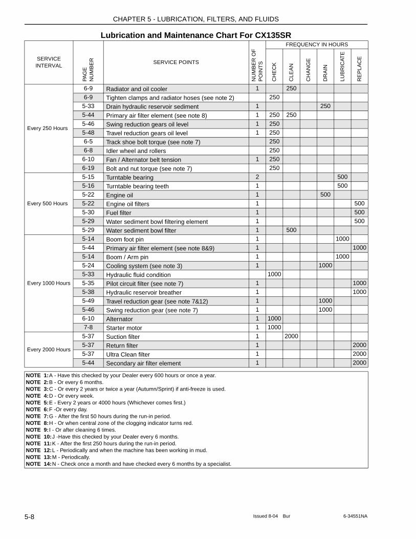
CHAPTER 5 - LUBRICATION, FILTERS, AND FLUIDS
Lubrication and Maintenance Chart For CX135SR
SERVICE INTERVAL
PAG
E
NU
MB
ER SERVICE POINTS
NU
MB
ER
OF
P
OIN
TS
FREQUENCY IN HOURS
CH
EC
K
CLE
AN
CH
AN
GE
DR
AIN
LUB
RIC
ATE
RE
PLA
CE
Every 250 Hours
6-9 Radiator and oil cooler 1 250
6-9 Tighten clamps and radiator hoses (see note 2) 2505-33 Drain hydraulic reservoir sediment 1 2505-44 Primary air filter element (see note 8) 1 250 250
5-46 Swing reduction gears oil level 1 2505-48 Travel reduction gears oil level 1 2506-5 Track shoe bolt torque (see note 7) 250
6-8 Idler wheel and rollers 2506-10 Fan / Alternator belt tension 1 2506-19 Bolt and nut torque (see note 7) 250
Every 500 Hours
5-15 Turntable bearing 2 5005-16 Turntable bearing teeth 1 5005-22 Engine oil 1 500
5-22 Engine oil filters 1 5005-30 Fuel filter 1 5005-29 Water sediment bowl filtering element 1 500
5-29 Water sediment bowl filter 1 500
Every 1000 Hours
5-14 Boom foot pin 1 10005-44 Primary air filter element (see note 8&9) 1 1000
5-14 Boom / Arm pin 1 10005-24 Cooling system (see note 3) 1 1000 5-33 Hydraulic fluid condition 1000
5-35 Pilot circuit filter (see note 7) 1 1000 5-38 Hydraulic reservoir breather 1 10005-49 Travel reduction gear (see note 7&12) 1 1000
5-46 Swing reduction gear (see note 7) 1 1000 6-10 Alternator 1 10007-8 Starter motor 1 1000
Every 2000 Hours
5-37 Suction filter 1 20005-37 Return filter 1 2000 5-37 Ultra Clean filter 1 2000
5-44 Secondary air filter element 1 2000
NOTE 1: A - Have this checked by your Dealer every 600 hours or once a year.NOTE 2: B - Or every 6 months.NOTE 3: C - Or every 2 years or twice a year (Autumn/Sprint) if anti-freeze is used.NOTE 4: D - Or every week.NOTE 5: E - Every 2 years or 4000 hours (Whichever comes first.)NOTE 6: F -Or every day.NOTE 7: G - After the first 50 hours during the run-in period.NOTE 8: H - Or when central zone of the clogging indicator turns red.NOTE 9: I - Or after cleaning 6 times.NOTE 10: J -Have this checked by your Dealer every 6 months.NOTE 11: K - After the first 250 hours during the run-in period.NOTE 12: L - Periodically and when the machine has been working in mud.NOTE 13: M - Periodically.NOTE 14: N - Check once a month and have checked every 6 months by a specialist.
5-8 Issued 8-04 Bur 6-34551NA
CHAPTER 5 - LUBRICATION, FILTERS, AND FLUIDS
FLUIDS AND LUBRICANTSLubricants must have the correct properties for each application.
Respect the maintenance intervals by checking the hourmeter every day. Before starting maintenance, park the machine on flat, firm ground, away from any obstacles, with the arm retracted and the bucket on the ground. Unless otherwise spec i f ied , a l l maintenance operations must be carried out with the engine stopped, and the key removed from the starter switch. It is preferable to wait for all circuits to cool down before starting work. Wear suitable clothing and remember to use the necessary safety equipment.
Clean the grease fittings before lubrication. Clean around plugs and filler holes before adding fluid. No dust or dirt must enter the components or the circuits.
When carrying out service work on the machine, place a “Do not operate” tag on the right-hand control arm. Never c l imb down f rom the opera tor ’s compartment leaving the engine running.
Any modification to this machine without prior authorization could cause serious injury. Do not make any modifications without authorization. Consult your Dealer.
IMPORTANT: If you use your machine in particularly harsh conditions (dusty or corrosive atmosphere, etc.), the servicing intervals should be reduced accordingly.
IMPORTANT: Take particular care to replace all filters regularly. Clean filters mean longer engine running life.
IMPORTANT: Oil and fluid should not be thrown on the ground. They must be stored and removed by a company which is responsible for their recycling or their disposal.
HYDRAULIC FLUID
CASE AKCELA hydraulic fluid is specially designed for high pressure applications and for the CASE hydraulic system.
TRANSMISSION COMPONENT OIL
Extreme pressure oil used for enclosed transmission components.
Extreme pressure oil type API GL5 grade 80W90 or ISO VG 150.
GREASE
The type of grease to use depends on ambient temperature.
Temperate and hot climates
-20°C to +60°C
Extreme pressure grease EP NLGI grade 2 with molybdenum disulphide.
Cold climates
-40°C to +20°C
Extreme pressure grease EP NLGI grade 0.
FUELUse diesel fuel suitable for the ambient temperature conditions (ASTM-D-975).
ENGINE OIL
CASE No. 1 motor oil is the oil recommended for your engine. This oil ensures correct lubrication of your engine in all working conditions.
WARNING: The conditions of use for individual fluids and lubricants must be respected.
WARNING: Be sure all the service operations in this section are carried out punctually at the intervals given, in order to ensure optimum performance levels and maximum safety when using the machine.
WARNING: There is a risk of serious injury if maintenance or repairs are not performed correctly. If you do not understand the maintenance procedures, consult your Dealer.
WARNING: If the attachment is raised or if the machine moves without an operator, serious injury can result. Before performing any maintenance, the following steps must be carried out:
1. Park the machine on flat, level ground.2. Lower the attachment until it is resting
on the ground.3. Stop the engine and remove the starter
switch key.4. Lock the tracks to prevent any machine
movement.
5-96-34551NA Issued 8-04 Bur
CHAPTER 5 - LUBRICATION, FILTERS, AND FLUIDS
CT02D203 Figure 2If CASE No. 1 Multi performance or Performance engine oil cannot be obtained, use only oil of the API/CG/CF category.
NOTE: Do not put any Performance Additive or other additive in the sump. Oil change intervals shown in this manual are based on tests carried out on CASE lubricants.
RB97F100 Figure 3
5-10 Issued 8-04 Bur 6-34551NA
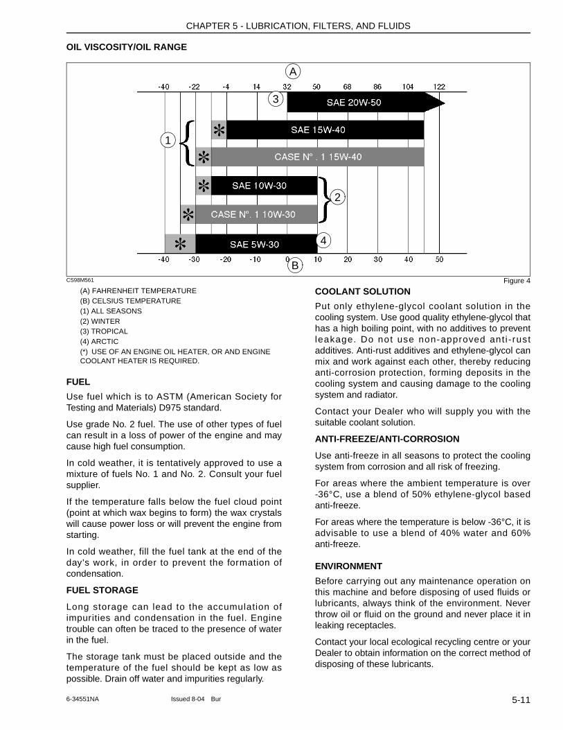
CHAPTER 5 - LUBRICATION, FILTERS, AND FLUIDS
OIL VISCOSITY/OIL RANGE
CS98M561 Figure 4(A) FAHRENHEIT TEMPERATURE(B) CELSIUS TEMPERATURE(1) ALL SEASONS(2) WINTER(3) TROPICAL(4) ARCTIC(*) USE OF AN ENGINE OIL HEATER, OR AND ENGINE COOLANT HEATER IS REQUIRED.
FUEL
Use fuel which is to ASTM (American Society for Testing and Materials) D975 standard.
Use grade No. 2 fuel. The use of other types of fuel can result in a loss of power of the engine and may cause high fuel consumption.
In cold weather, it is tentatively approved to use a mixture of fuels No. 1 and No. 2. Consult your fuel supplier.
If the temperature falls below the fuel cloud point (point at which wax begins to form) the wax crystals will cause power loss or will prevent the engine from starting.
In cold weather, fill the fuel tank at the end of the day's work, in order to prevent the formation of condensation.
FUEL STORAGE
Long storage can lead to the accumulation of impurities and condensation in the fuel. Engine trouble can often be traced to the presence of water in the fuel.
The storage tank must be placed outside and the temperature of the fuel should be kept as low as possible. Drain off water and impurities regularly.
COOLANT SOLUTION
Put only ethylene-glycol coolant solution in the cooling system. Use good quality ethylene-glycol that has a high boiling point, with no additives to prevent leakage. Do not use non-approved ant i - rust additives. Anti-rust additives and ethylene-glycol can mix and work against each other, thereby reducing anti-corrosion protection, forming deposits in the cooling system and causing damage to the cooling system and radiator.
Contact your Dealer who will supply you with the suitable coolant solution.
ANTI-FREEZE/ANTI-CORROSION
Use anti-freeze in all seasons to protect the cooling system from corrosion and all risk of freezing.
For areas where the ambient temperature is over -36°C, use a blend of 50% ethylene-glycol based anti-freeze.
For areas where the temperature is below -36°C, it is advisable to use a blend of 40% water and 60% anti-freeze.
ENVIRONMENT
Before carrying out any maintenance operation on this machine and before disposing of used fluids or lubricants, always think of the environment. Never throw oil or fluid on the ground and never place it in leaking receptacles.
Contact your local ecological recycling centre or your Dealer to obtain information on the correct method of disposing of these lubricants.
A
B
1
2
3
4
5-116-34551NA Issued 8-04 Bur
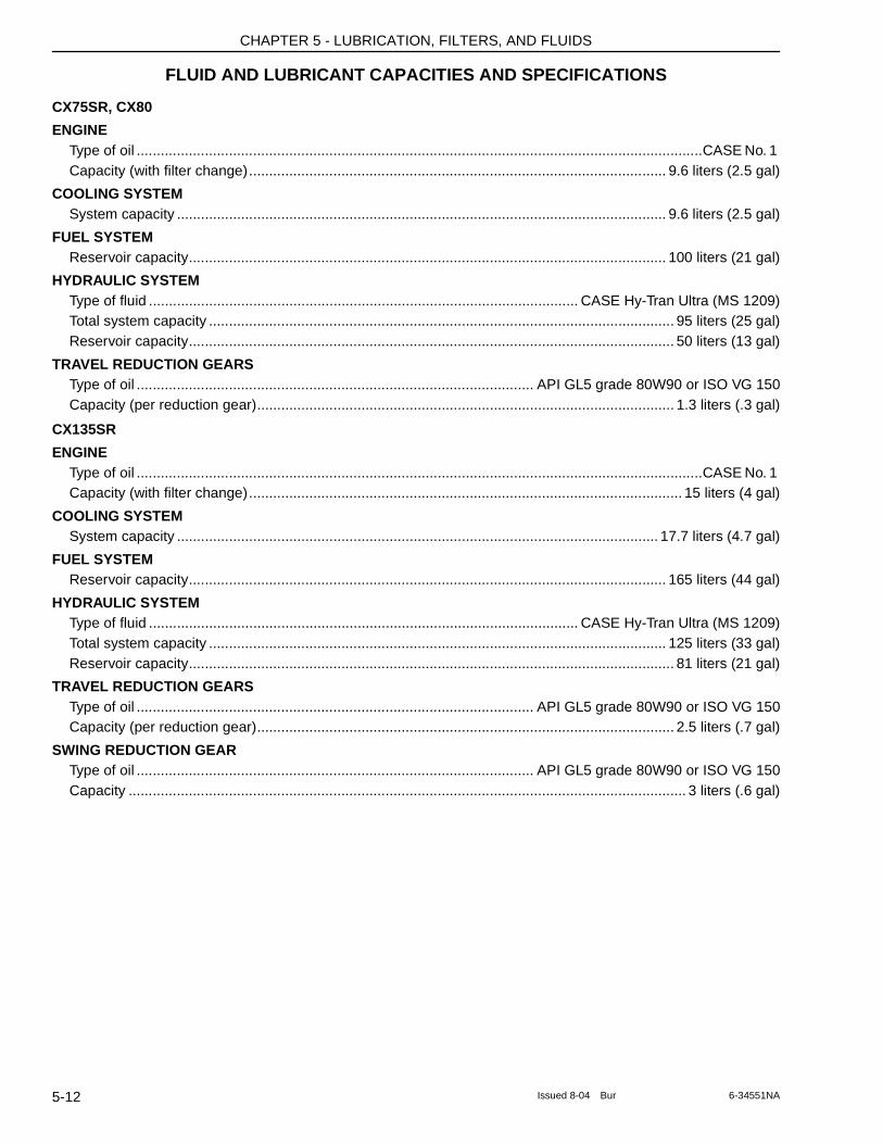
CHAPTER 5 - LUBRICATION, FILTERS, AND FLUIDS
FLUID AND LUBRICANT CAPACITIES AND SPECIFICATIONS
CX75SR, CX80
ENGINEType of oil .............................................................................................................................................CASE No. 1 Capacity (with filter change)........................................................................................................ 9.6 liters (2.5 gal)
COOLING SYSTEMSystem capacity .......................................................................................................................... 9.6 liters (2.5 gal)
FUEL SYSTEMReservoir capacity....................................................................................................................... 100 liters (21 gal)
HYDRAULIC SYSTEMType of fluid ........................................................................................................... CASE Hy-Tran Ultra (MS 1209)Total system capacity .................................................................................................................... 95 liters (25 gal)Reservoir capacity......................................................................................................................... 50 liters (13 gal)
TRAVEL REDUCTION GEARSType of oil ................................................................................................... API GL5 grade 80W90 or ISO VG 150Capacity (per reduction gear)........................................................................................................ 1.3 liters (.3 gal)
CX135SR
ENGINEType of oil .............................................................................................................................................CASE No. 1 Capacity (with filter change)............................................................................................................ 15 liters (4 gal)
COOLING SYSTEMSystem capacity ........................................................................................................................ 17.7 liters (4.7 gal)
FUEL SYSTEMReservoir capacity....................................................................................................................... 165 liters (44 gal)
HYDRAULIC SYSTEMType of fluid ........................................................................................................... CASE Hy-Tran Ultra (MS 1209)Total system capacity .................................................................................................................. 125 liters (33 gal)Reservoir capacity......................................................................................................................... 81 liters (21 gal)
TRAVEL REDUCTION GEARSType of oil ................................................................................................... API GL5 grade 80W90 or ISO VG 150Capacity (per reduction gear)........................................................................................................ 2.5 liters (.7 gal)
SWING REDUCTION GEARType of oil ................................................................................................... API GL5 grade 80W90 or ISO VG 150Capacity ........................................................................................................................................... 3 liters (.6 gal)
5-12 Issued 8-04 Bur 6-34551NA
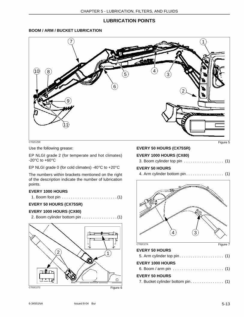
CHAPTER 5 - LUBRICATION, FILTERS, AND FLUIDS
LUBRICATION POINTS
BOOM / ARM / BUCKET LUBRICATION
CT02C259 Figure 5
Use the following grease:
EP NLGI grade 2 (for temperate and hot climates) -20°C to +60°C
EP NLGI grade 0 (for cold climates) -40°C to +20°C
The numbers within brackets mentioned on the right of the description indicate the number of lubrication points.
EVERY 1000 HOURS1. Boom foot pin . . . . . . . . . . . . . . . . . . . . . . . . . (1)
EVERY 50 HOURS (CX75SR)
EVERY 1000 HOURS (CX80)2. Boom cylinder bottom pin . . . . . . . . . . . . . . . . (1)
CT02C272 Figure 6
EVERY 50 HOURS (CX75SR)
EVERY 1000 HOURS (CX80)3. Boom cylinder top pin . . . . . . . . . . . . . . . . . . (1)
EVERY 50 HOURS4. Arm cylinder bottom pin . . . . . . . . . . . . . . . . . (1)
CT02C274 Figure 7
EVERY 50 HOURS5. Arm cylinder top pin . . . . . . . . . . . . . . . . . . . . (1)
EVERY 1000 HOURS6. Boom / arm pin . . . . . . . . . . . . . . . . . . . . . . . (1)
EVERY 50 HOURS7. Bucket cylinder bottom pin . . . . . . . . . . . . . . . (1)
5
1
43
11
7
9
2
810
6
2 1
34
5-136-34551NA Issued 8-04 Bur
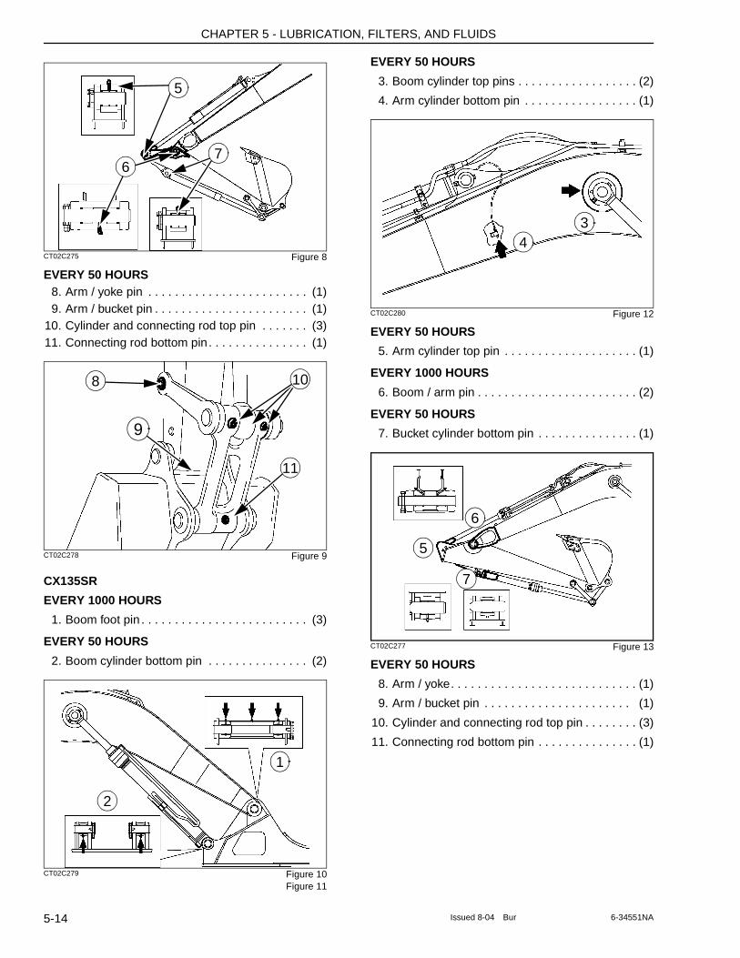
CHAPTER 5 - LUBRICATION, FILTERS, AND FLUIDS
CT02C275 Figure 8
EVERY 50 HOURS8. Arm / yoke pin . . . . . . . . . . . . . . . . . . . . . . . . (1)9. Arm / bucket pin . . . . . . . . . . . . . . . . . . . . . . . (1)
10. Cylinder and connecting rod top pin . . . . . . . (3)11. Connecting rod bottom pin. . . . . . . . . . . . . . . (1)
CT02C278 Figure 9
CX135SR
EVERY 1000 HOURS
1. Boom foot pin . . . . . . . . . . . . . . . . . . . . . . . . . (3)
EVERY 50 HOURS
2. Boom cylinder bottom pin . . . . . . . . . . . . . . . (2)
CT02C279 Figure 10Figure 11
EVERY 50 HOURS
3. Boom cylinder top pins . . . . . . . . . . . . . . . . . . (2)
4. Arm cylinder bottom pin . . . . . . . . . . . . . . . . . (1)
CT02C280 Figure 12
EVERY 50 HOURS
5. Arm cylinder top pin . . . . . . . . . . . . . . . . . . . . (1)
EVERY 1000 HOURS
6. Boom / arm pin . . . . . . . . . . . . . . . . . . . . . . . . (2)
EVERY 50 HOURS
7. Bucket cylinder bottom pin . . . . . . . . . . . . . . . (1)
CT02C277 Figure 13
EVERY 50 HOURS
8. Arm / yoke. . . . . . . . . . . . . . . . . . . . . . . . . . . . (1)
9. Arm / bucket pin . . . . . . . . . . . . . . . . . . . . . . (1)
10. Cylinder and connecting rod top pin . . . . . . . . (3)
11. Connecting rod bottom pin . . . . . . . . . . . . . . . (1)
5
76
8
9
10
11
1
2
34
6
5
7
5-14 Issued 8-04 Bur 6-34551NA
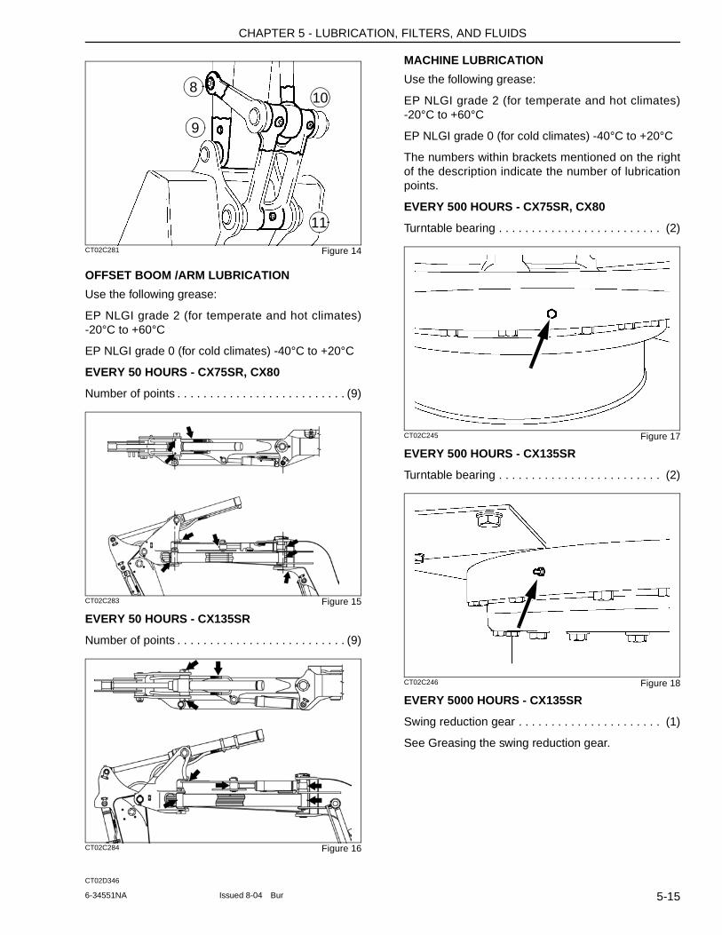
CHAPTER 5 - LUBRICATION, FILTERS, AND FLUIDS
CT02C281 Figure 14
OFFSET BOOM /ARM LUBRICATION
Use the following grease:
EP NLGI grade 2 (for temperate and hot climates) -20°C to +60°C
EP NLGI grade 0 (for cold climates) -40°C to +20°C
EVERY 50 HOURS - CX75SR, CX80
Number of points . . . . . . . . . . . . . . . . . . . . . . . . . . (9)
CT02C283 Figure 15
EVERY 50 HOURS - CX135SR
Number of points . . . . . . . . . . . . . . . . . . . . . . . . . . (9)
CT02C284 Figure 16
CT02D346
MACHINE LUBRICATION
Use the following grease:
EP NLGI grade 2 (for temperate and hot climates) -20°C to +60°C
EP NLGI grade 0 (for cold climates) -40°C to +20°C
The numbers within brackets mentioned on the right of the description indicate the number of lubrication points.
EVERY 500 HOURS - CX75SR, CX80
Turntable bearing . . . . . . . . . . . . . . . . . . . . . . . . . (2)
CT02C245 Figure 17
EVERY 500 HOURS - CX135SR
Turntable bearing . . . . . . . . . . . . . . . . . . . . . . . . . (2)
CT02C246 Figure 18
EVERY 5000 HOURS - CX135SR
Swing reduction gear . . . . . . . . . . . . . . . . . . . . . . (1)
See Greasing the swing reduction gear.
108
11
9
5-156-34551NA Issued 8-04 Bur
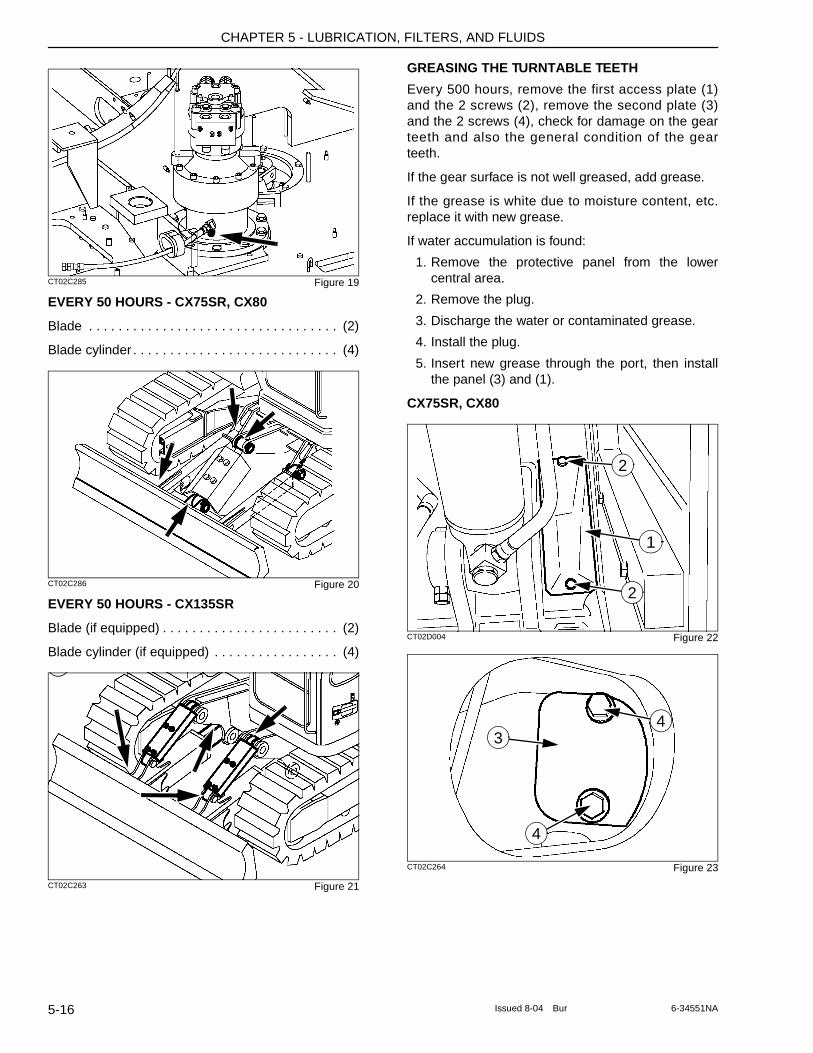
CHAPTER 5 - LUBRICATION, FILTERS, AND FLUIDS
CT02C285 Figure 19
EVERY 50 HOURS - CX75SR, CX80
Blade . . . . . . . . . . . . . . . . . . . . . . . . . . . . . . . . . . (2)
Blade cylinder . . . . . . . . . . . . . . . . . . . . . . . . . . . . (4)
CT02C286 Figure 20
EVERY 50 HOURS - CX135SR
Blade (if equipped) . . . . . . . . . . . . . . . . . . . . . . . . (2)
Blade cylinder (if equipped) . . . . . . . . . . . . . . . . . (4)
CT02C263 Figure 21
GREASING THE TURNTABLE TEETH
Every 500 hours, remove the first access plate (1) and the 2 screws (2), remove the second plate (3) and the 2 screws (4), check for damage on the gear teeth and also the general condition of the gear teeth.
If the gear surface is not well greased, add grease.
If the grease is white due to moisture content, etc. replace it with new grease.
If water accumulation is found:
1. Remove the protective panel from the lower central area.
2. Remove the plug.
3. Discharge the water or contaminated grease.
4. Install the plug.
5. Insert new grease through the port, then install the panel (3) and (1).
CX75SR, CX80
CT02D004 Figure 22
CT02C264 Figure 23
1
2
2
3
4
4
5-16 Issued 8-04 Bur 6-34551NA
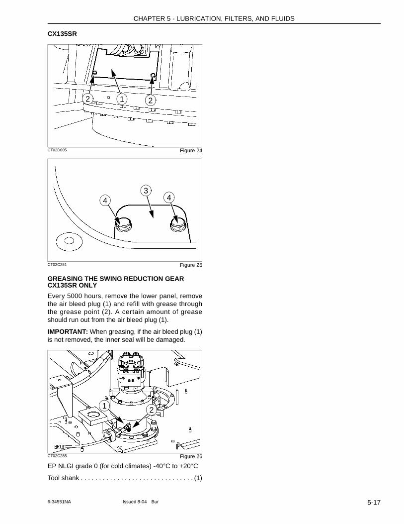
CHAPTER 5 - LUBRICATION, FILTERS, AND FLUIDS
CX135SR
CT02D005 Figure 24
CT02C251 Figure 25
GREASING THE SWING REDUCTION GEAR CX135SR ONLY
Every 5000 hours, remove the lower panel, remove the air bleed plug (1) and refill with grease through the grease point (2). A certain amount of grease should run out from the air bleed plug (1).
IMPORTANT: When greasing, if the air bleed plug (1) is not removed, the inner seal will be damaged.
CT02C285 Figure 26
EP NLGI grade 0 (for cold climates) -40°C to +20°C
Tool shank . . . . . . . . . . . . . . . . . . . . . . . . . . . . . . . (1)
1 22
43
4
1 2
5-176-34551NA Issued 8-04 Bur
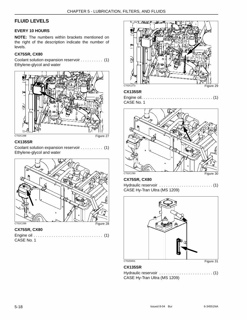
CHAPTER 5 - LUBRICATION, FILTERS, AND FLUIDS
FLUID LEVELS
EVERY 10 HOURS
NOTE: The numbers within brackets mentioned on the right of the description indicate the number of levels.
CX75SR, CX80Coolant solution expansion reservoir . . . . . . . . . . (1)Ethylene-glycol and water
CT02C288 Figure 27
CX135SRCoolant solution expansion reservoir . . . . . . . . . . (1)Ethylene-glycol and water
CT02C289 Figure 28
CX75SR, CX80Engine oil . . . . . . . . . . . . . . . . . . . . . . . . . . . . . . . (1)CASE No. 1
CT02C273 Figure 29
CX135SREngine oil. . . . . . . . . . . . . . . . . . . . . . . . . . . . . . . . (1)CASE No. 1
CT02C290 Figure 30
CX75SR, CX80Hydraulic reservoir . . . . . . . . . . . . . . . . . . . . . . . . (1)CASE Hy-Tran Ultra (MS 1209)
CT02D001 Figure 31
CX135SRHydraulic reservoir . . . . . . . . . . . . . . . . . . . . . . . . (1)CASE Hy-Tran Ultra (MS 1209)
5-18 Issued 8-04 Bur 6-34551NA
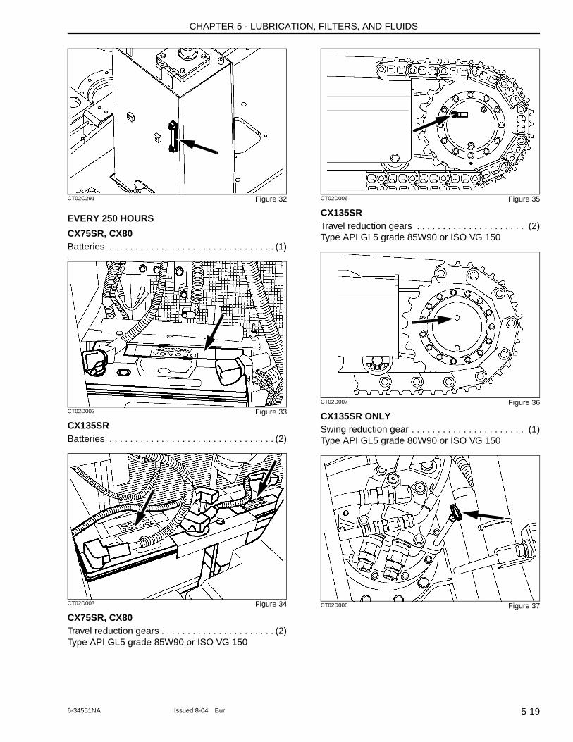
CHAPTER 5 - LUBRICATION, FILTERS, AND FLUIDS
CT02C291 Figure 32
EVERY 250 HOURS
CX75SR, CX80Batteries . . . . . . . . . . . . . . . . . . . . . . . . . . . . . . . . (1)\
CT02D002 Figure 33
CX135SRBatteries . . . . . . . . . . . . . . . . . . . . . . . . . . . . . . . . (2)
CT02D003 Figure 34
CX75SR, CX80Travel reduction gears . . . . . . . . . . . . . . . . . . . . . . (2)Type API GL5 grade 85W90 or ISO VG 150
CT02D006 Figure 35
CX135SRTravel reduction gears . . . . . . . . . . . . . . . . . . . . . (2)Type API GL5 grade 85W90 or ISO VG 150
CT02D007 Figure 36
CX135SR ONLYSwing reduction gear . . . . . . . . . . . . . . . . . . . . . . (1)Type API GL5 grade 80W90 or ISO VG 150
CT02D008 Figure 37
5-196-34551NA Issued 8-04 Bur
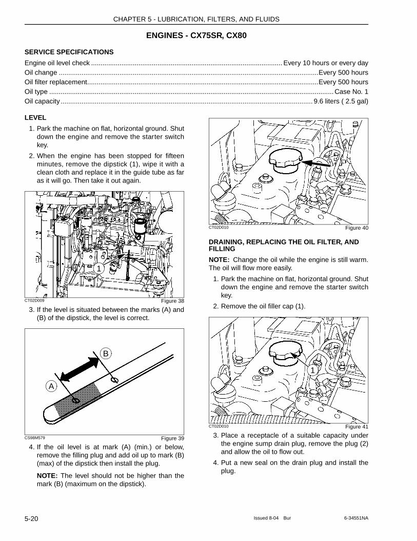
CHAPTER 5 - LUBRICATION, FILTERS, AND FLUIDS
ENGINES - CX75SR, CX80
SERVICE SPECIFICATIONS
Engine oil level check ..................................................................................................... Every 10 hours or every dayOil change .........................................................................................................................................Every 500 hoursOil filter replacement..........................................................................................................................Every 500 hoursOil type ...................................................................................................................................................... Case No. 1Oil capacity ..................................................................................................................................... 9.6 liters ( 2.5 gal)
LEVEL
1. Park the machine on flat, horizontal ground. Shut down the engine and remove the starter switch key.
2. When the engine has been stopped for fifteen minutes, remove the dipstick (1), wipe it with a clean cloth and replace it in the guide tube as far as it will go. Then take it out again.
CT02D009 Figure 38
3. If the level is situated between the marks (A) and (B) of the dipstick, the level is correct.
CS98M579 Figure 39
4. If the oil level is at mark (A) (min.) or below, remove the filling plug and add oil up to mark (B) (max) of the dipstick then install the plug.
NOTE: The level should not be higher than the mark (B) (maximum on the dipstick).
CT02D010 Figure 40
DRAINING, REPLACING THE OIL FILTER, AND FILLING
NOTE: Change the oil while the engine is still warm. The oil will flow more easily.
1. Park the machine on flat, horizontal ground. Shut down the engine and remove the starter switch key.
2. Remove the oil filler cap (1).
CT02D010 Figure 41
3. Place a receptacle of a suitable capacity under the engine sump drain plug, remove the plug (2) and allow the oil to flow out.
4. Put a new seal on the drain plug and install the plug.
1
A
B
1
5-20 Issued 8-04 Bur 6-34551NA
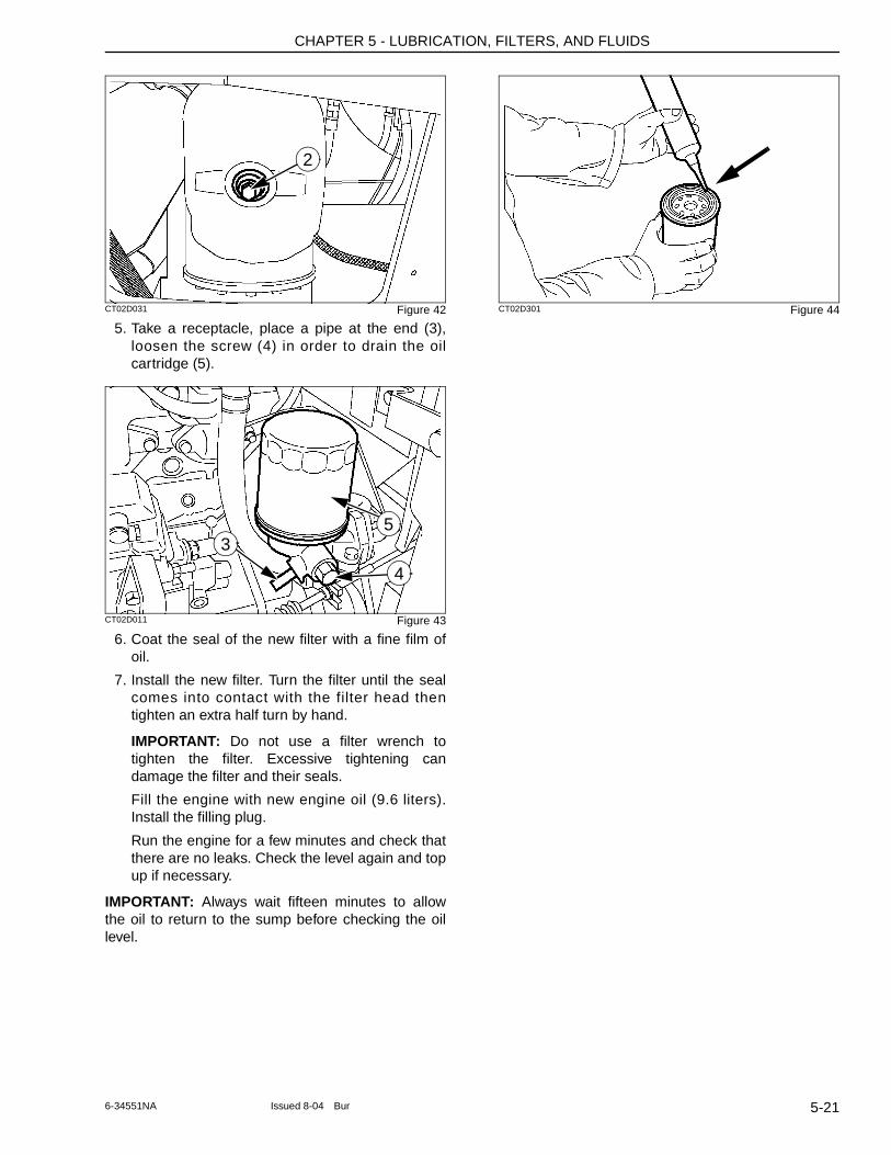
CHAPTER 5 - LUBRICATION, FILTERS, AND FLUIDS
CT02D031 Figure 42
5. Take a receptacle, place a pipe at the end (3), loosen the screw (4) in order to drain the oil cartridge (5).
CT02D011 Figure 43
6. Coat the seal of the new filter with a fine film of oil.
7. Install the new filter. Turn the filter until the seal comes into contact with the filter head then tighten an extra half turn by hand.
IMPORTANT: Do not use a filter wrench to tighten the filter. Excessive tightening can damage the filter and their seals.
Fill the engine with new engine oil (9.6 liters). Install the filling plug.
Run the engine for a few minutes and check that there are no leaks. Check the level again and top up if necessary.
IMPORTANT: Always wait fifteen minutes to allow the oil to return to the sump before checking the oil level.
CT02D301 Figure 44
2
35
4
5-216-34551NA Issued 8-04 Bur
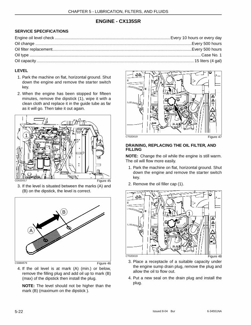
CHAPTER 5 - LUBRICATION, FILTERS, AND FLUIDS
ENGINE - CX135SR
SERVICE SPECIFICATIONS
Engine oil level check ..................................................................................................... Every 10 hours or every dayOil change .........................................................................................................................................Every 500 hoursOil filter replacement..........................................................................................................................Every 500 hoursOil type ...................................................................................................................................................... Case No. 1Oil capacity .......................................................................................................................................... 15 liters (4 gal)
LEVEL
1. Park the machine on flat, horizontal ground. Shut down the engine and remove the starter switch key.
2. When the engine has been stopped for fifteen minutes, remove the dipstick (1), wipe it with a clean cloth and replace it in the guide tube as far as it will go. Then take it out again.
CD02D017 Figure 45
3. If the level is situated between the marks (A) and (B) on the dipstick, the level is correct.
CS98M579 Figure 46
4. If the oil level is at mark (A) (min.) or below, remove the filling plug and add oil up to mark (B) (max) of the dipstick then install the plug.
NOTE: The level should not be higher than the mark (B) (maximum on the dipstick ).
CT02D019 Figure 47
DRAINING, REPLACING THE OIL FILTER, AND FILLING
NOTE: Change the oil while the engine is still warm. The oil will flow more easily.
1. Park the machine on flat, horizontal ground. Shut down the engine and remove the starter switch key.
2. Remove the oil filler cap (1).
CT02D019 Figure 48
3. Place a receptacle of a suitable capacity under the engine sump drain plug, remove the plug and allow the oil to flow out.
4. Put a new seal on the drain plug and install the plug.
1
A
B 1
5-22 Issued 8-04 Bur 6-34551NA
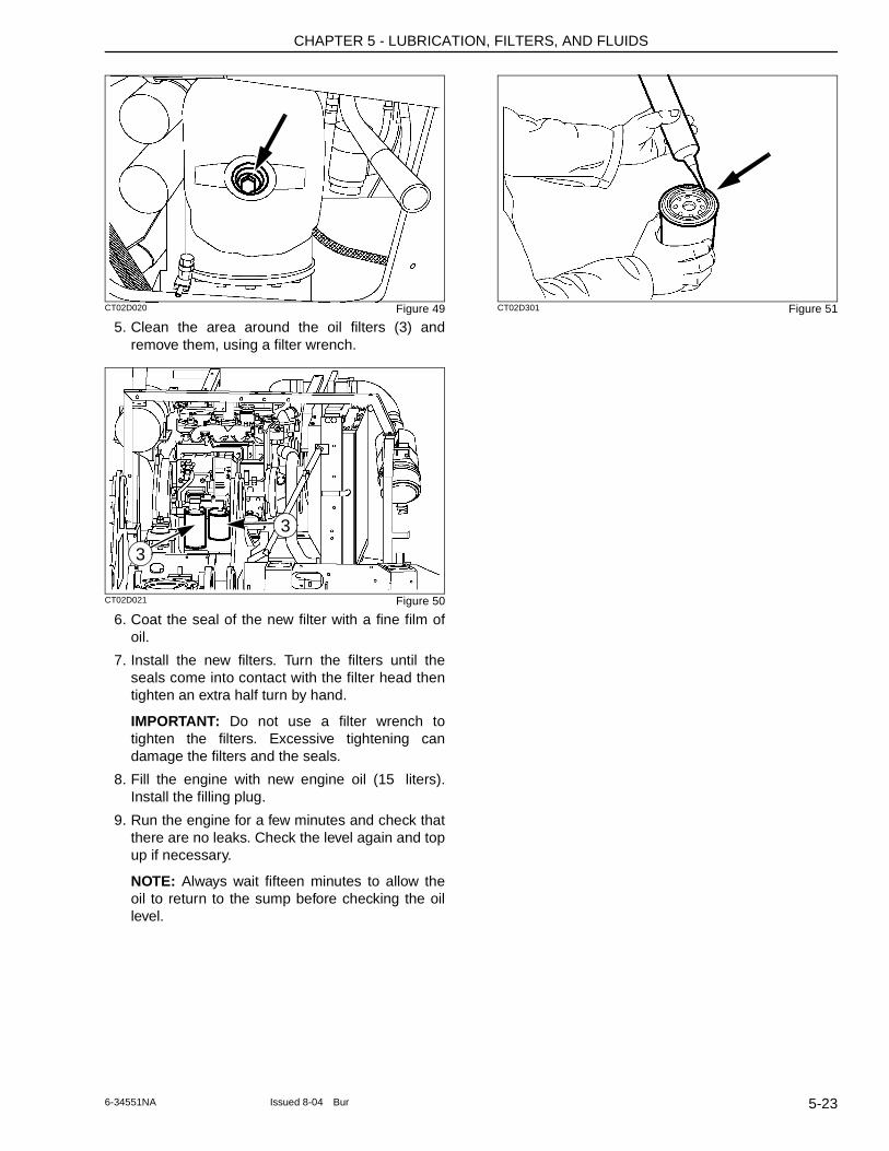
CHAPTER 5 - LUBRICATION, FILTERS, AND FLUIDS
CT02D020 Figure 49
5. Clean the area around the oil filters (3) and remove them, using a filter wrench.
CT02D021 Figure 50
6. Coat the seal of the new filter with a fine film of oil.
7. Install the new filters. Turn the filters until the seals come into contact with the filter head then tighten an extra half turn by hand.
IMPORTANT: Do not use a filter wrench to tighten the filters. Excessive tightening can damage the filters and the seals.
8. Fill the engine with new engine oil (15 liters). Install the filling plug.
9. Run the engine for a few minutes and check that there are no leaks. Check the level again and top up if necessary.
NOTE: Always wait fifteen minutes to allow the oil to return to the sump before checking the oil level.
CT02D301 Figure 51
3
3
5-236-34551NA Issued 8-04 Bur
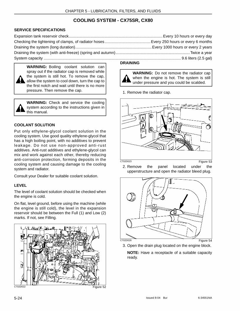
CHAPTER 5 - LUBRICATION, FILTERS, AND FLUIDS
COOLING SYSTEM - CX75SR, CX80
SERVICE SPECIFICATIONS
Expansion tank reservoir check...................................................................................... Every 10 hours or every dayChecking the tightening of clamps, of radiator hoses ..........................................Every 250 hours or every 6 monthsDraining the system (long duration)......................................................................Every 1000 hours or every 2 yearsDraining the system (with anti-freeze) (spring and autumn)....................................................................Twice a yearSystem capacity .............................................................................................................................. 9.6 liters (2.5 gal)
COOLANT SOLUTION
Put only ethylene-glycol coolant solution in the cooling system. Use good quality ethylene-glycol that has a high boiling point, with no additives to prevent leakage. Do not use non-approved ant i - rust additives. Anti-rust additives and ethylene-glycol can mix and work against each other, thereby reducing anti-corrosion protection, forming deposits in the cooling system and causing damage to the cooling system and radiator.
Consult your Dealer for suitable coolant solution.
LEVEL
The level of coolant solution should be checked when the engine is cold.
On flat, level ground, before using the machine (while the engine is still cold), the level in the expansion reservoir should be between the Full (1) and Low (2) marks. If not, see Filling.
CT02D022 Figure 52
DRAINING
1. Remove the radiator cap.
CT02D023 Figure 53
2. Remove the panel located under the upperstructure and open the radiator bleed plug.
CT02D026 Figure 54
3. Open the drain plug located on the engine block.
NOTE: Have a receptacle of a suitable capacity ready.
WARNING: Boiling coolant solution can spray out if the radiator cap is removed while the system is still hot. To remove the cap, allow the system to cool down, turn the cap to the first notch and wait until there is no more pressure. Then remove the cap.
WARNING: Check and service the cooling system according to the instructions given in this manual.
2
1
WARNING: Do not remove the radiator cap when the engine is hot. The system is still under pressure and you could be scalded.
5-24 Issued 8-04 Bur 6-34551NA
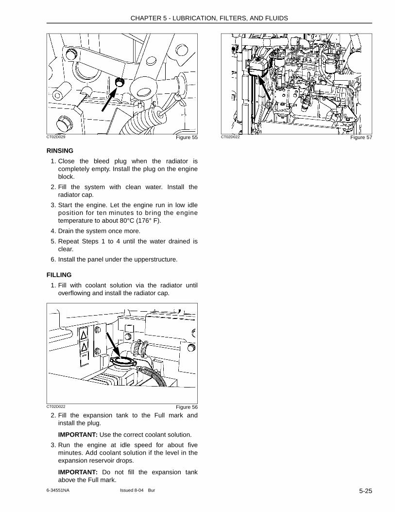
CHAPTER 5 - LUBRICATION, FILTERS, AND FLUIDS
CT02D029 Figure 55
RINSING
1. Close the bleed plug when the radiator is completely empty. Install the plug on the engine block.
2. Fill the system with clean water. Install the radiator cap.
3. Start the engine. Let the engine run in low idle position for ten minutes to bring the engine temperature to about 80°C (176° F).
4. Drain the system once more.
5. Repeat Steps 1 to 4 until the water drained is clear.
6. Install the panel under the upperstructure.
FILLING
1. Fill with coolant solution via the radiator until overflowing and install the radiator cap.
CT02D022 Figure 56
2. Fill the expansion tank to the Full mark and install the plug.
IMPORTANT: Use the correct coolant solution.
3. Run the engine at idle speed for about five minutes. Add coolant solution if the level in the expansion reservoir drops.
IMPORTANT: Do not fill the expansion tank above the Full mark.
CT02D022 Figure 57
5-256-34551NA Issued 8-04 Bur
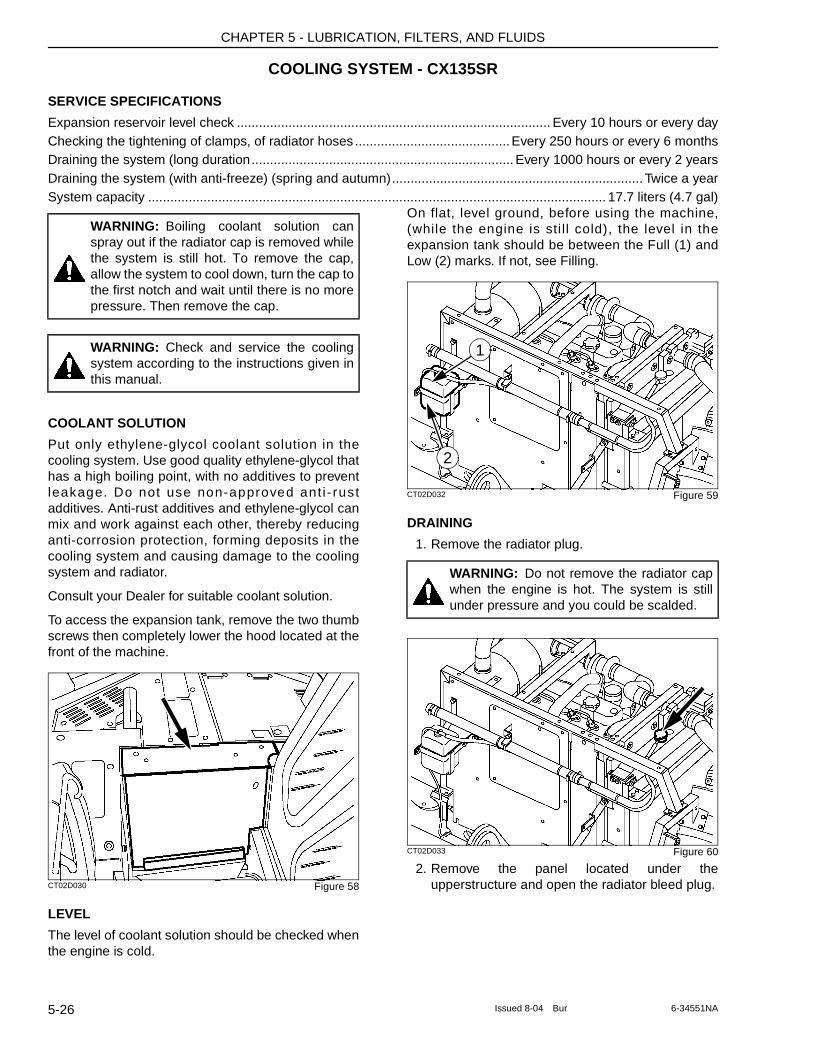
CHAPTER 5 - LUBRICATION, FILTERS, AND FLUIDS
COOLING SYSTEM - CX135SR
SERVICE SPECIFICATIONS
Expansion reservoir level check ..................................................................................... Every 10 hours or every dayChecking the tightening of clamps, of radiator hoses ..........................................Every 250 hours or every 6 monthsDraining the system (long duration....................................................................... Every 1000 hours or every 2 yearsDraining the system (with anti-freeze) (spring and autumn)....................................................................Twice a yearSystem capacity ............................................................................................................................ 17.7 liters (4.7 gal)
COOLANT SOLUTION
Put only ethylene-glycol coolant solution in the cooling system. Use good quality ethylene-glycol that has a high boiling point, with no additives to prevent leakage. Do not use non-approved ant i - rust additives. Anti-rust additives and ethylene-glycol can mix and work against each other, thereby reducing anti-corrosion protection, forming deposits in the cooling system and causing damage to the cooling system and radiator.
Consult your Dealer for suitable coolant solution.
To access the expansion tank, remove the two thumb screws then completely lower the hood located at the front of the machine.
CT02D030 Figure 58
LEVEL
The level of coolant solution should be checked when the engine is cold.
On flat, level ground, before using the machine, (while the engine is sti ll cold), the level in the expansion tank should be between the Full (1) and Low (2) marks. If not, see Filling.
CT02D032 Figure 59
DRAINING
1. Remove the radiator plug.
CT02D033 Figure 60
2. Remove the panel located under the upperstructure and open the radiator bleed plug.
WARNING: Boiling coolant solution can spray out if the radiator cap is removed while the system is still hot. To remove the cap, allow the system to cool down, turn the cap to the first notch and wait until there is no more pressure. Then remove the cap.
WARNING: Check and service the cooling system according to the instructions given in this manual.
WARNING: Do not remove the radiator cap when the engine is hot. The system is still under pressure and you could be scalded.
2
1
5-26 Issued 8-04 Bur 6-34551NA
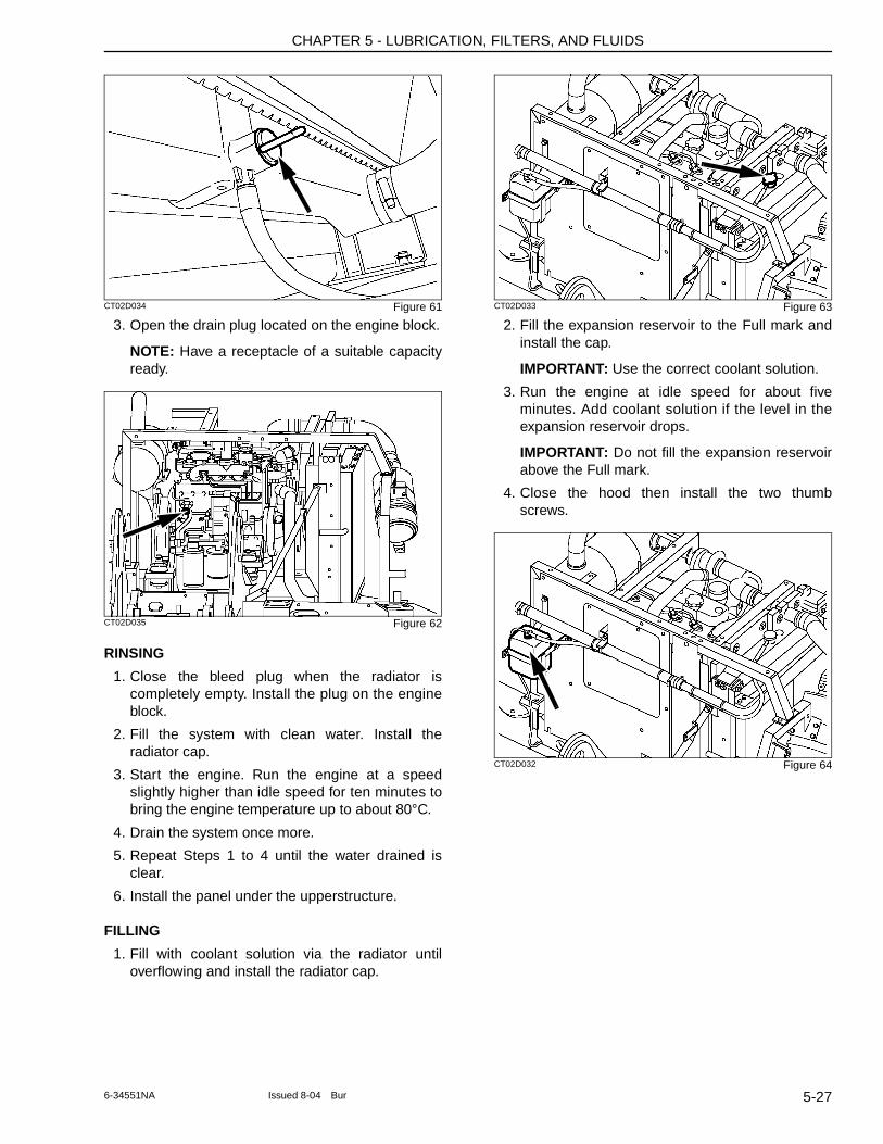
CHAPTER 5 - LUBRICATION, FILTERS, AND FLUIDS
CT02D034 Figure 61
3. Open the drain plug located on the engine block.
NOTE: Have a receptacle of a suitable capacity ready.
CT02D035 Figure 62
RINSING
1. Close the bleed plug when the radiator is completely empty. Install the plug on the engine block.
2. Fill the system with clean water. Install the radiator cap.
3. Start the engine. Run the engine at a speed slightly higher than idle speed for ten minutes to bring the engine temperature up to about 80°C.
4. Drain the system once more.
5. Repeat Steps 1 to 4 until the water drained is clear.
6. Install the panel under the upperstructure.
FILLING
1. Fill with coolant solution via the radiator until overflowing and install the radiator cap.
CT02D033 Figure 63
2. Fill the expansion reservoir to the Full mark and install the cap.
IMPORTANT: Use the correct coolant solution.
3. Run the engine at idle speed for about five minutes. Add coolant solution if the level in the expansion reservoir drops.
IMPORTANT: Do not fill the expansion reservoir above the Full mark.
4. Close the hood then install the two thumb screws.
CT02D032 Figure 64
5-276-34551NA Issued 8-04 Bur
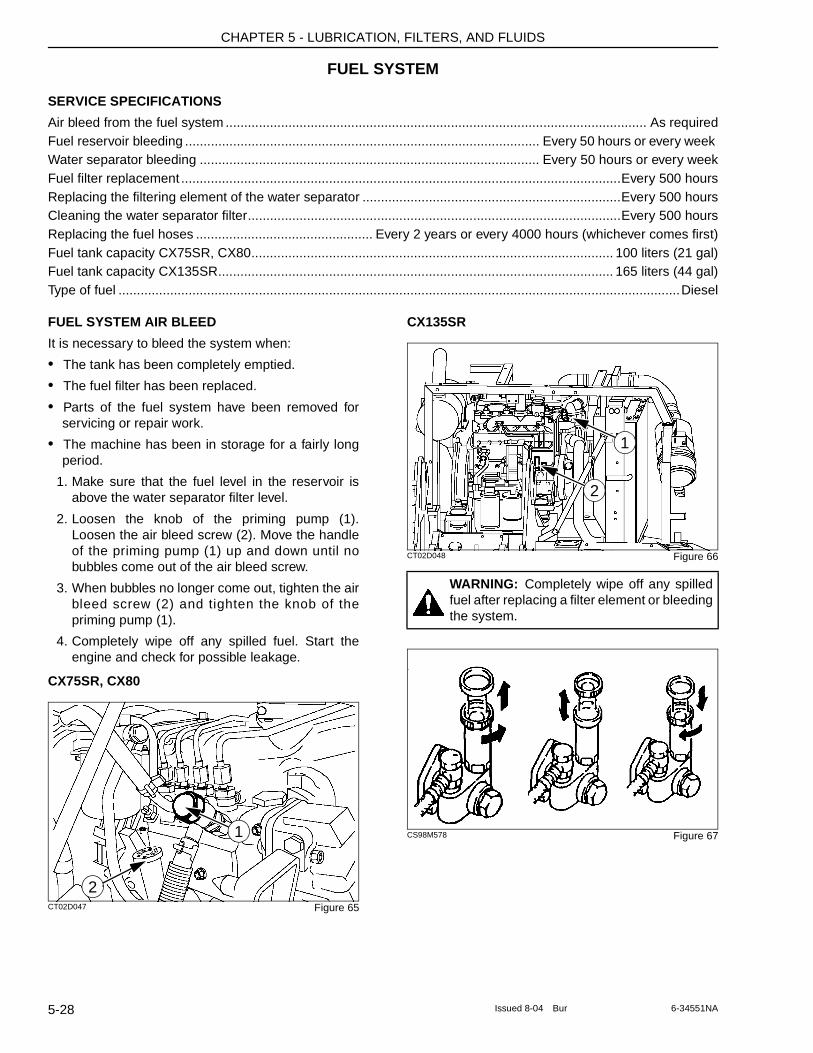
CHAPTER 5 - LUBRICATION, FILTERS, AND FLUIDS
FUEL SYSTEM
SERVICE SPECIFICATIONS
Air bleed from the fuel system .................................................................................................................. As requiredFuel reservoir bleeding ................................................................................................ Every 50 hours or every week Water separator bleeding ............................................................................................ Every 50 hours or every weekFuel filter replacement .......................................................................................................................Every 500 hoursReplacing the filtering element of the water separator ......................................................................Every 500 hoursCleaning the water separator filter.....................................................................................................Every 500 hoursReplacing the fuel hoses ................................................ Every 2 years or every 4000 hours (whichever comes first)Fuel tank capacity CX75SR, CX80.................................................................................................. 100 liters (21 gal)Fuel tank capacity CX135SR........................................................................................................... 165 liters (44 gal)Type of fuel ........................................................................................................................................................Diesel
FUEL SYSTEM AIR BLEED
It is necessary to bleed the system when:
• The tank has been completely emptied.
• The fuel filter has been replaced.
• Parts of the fuel system have been removed for servicing or repair work.
• The machine has been in storage for a fairly long period.
1. Make sure that the fuel level in the reservoir is above the water separator filter level.
2. Loosen the knob of the priming pump (1). Loosen the air bleed screw (2). Move the handle of the priming pump (1) up and down until no bubbles come out of the air bleed screw.
3. When bubbles no longer come out, tighten the air bleed screw (2) and tighten the knob of the priming pump (1).
4. Completely wipe off any spilled fuel. Start the engine and check for possible leakage.
CX75SR, CX80
CT02D047 Figure 65
CX135SR
CT02D048 Figure 66
CS98M578 Figure 671
2
WARNING: Completely wipe off any spilled fuel after replacing a filter element or bleeding the system.
2
1
5-28 Issued 8-04 Bur 6-34551NA
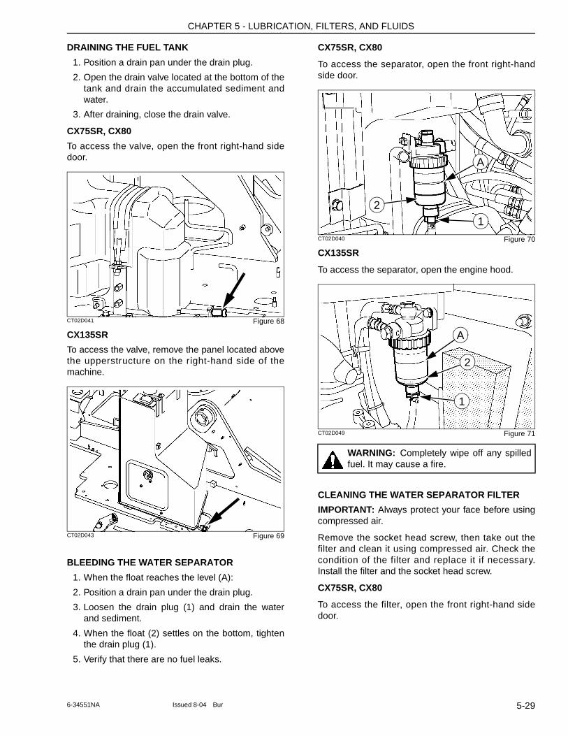
CHAPTER 5 - LUBRICATION, FILTERS, AND FLUIDS
DRAINING THE FUEL TANK
1. Position a drain pan under the drain plug.
2. Open the drain valve located at the bottom of the tank and drain the accumulated sediment and water.
3. After draining, close the drain valve.
CX75SR, CX80
To access the valve, open the front right-hand side door.
CT02D041 Figure 68
CX135SR
To access the valve, remove the panel located above the upperstructure on the right-hand side of the machine.
CT02D043 Figure 69
BLEEDING THE WATER SEPARATOR
1. When the float reaches the level (A):
2. Position a drain pan under the drain plug.
3. Loosen the drain plug (1) and drain the water and sediment.
4. When the float (2) settles on the bottom, tighten the drain plug (1).
5. Verify that there are no fuel leaks.
CX75SR, CX80
To access the separator, open the front right-hand side door.
CT02D040 Figure 70
CX135SR
To access the separator, open the engine hood.
CT02D049 Figure 71
CLEANING THE WATER SEPARATOR FILTER
IMPORTANT: Always protect your face before using compressed air.
Remove the socket head screw, then take out the filter and clean it using compressed air. Check the condition of the filter and replace it if necessary. Install the filter and the socket head screw.
CX75SR, CX80
To access the filter, open the front right-hand side door.
WARNING: Completely wipe off any spilled fuel. It may cause a fire.
A
2
1
1
2
A
5-296-34551NA Issued 8-04 Bur
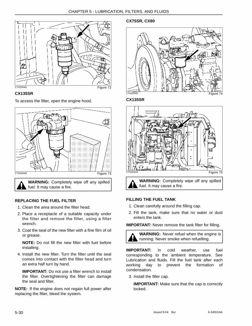
CHAPTER 5 - LUBRICATION, FILTERS, AND FLUIDS
(
CT02D040 Figure 72
CX135SR
To access the filter, open the engine hood.
CT02D049 Figure 73
REPLACING THE FUEL FILTER
1. Clean the area around the filter head.
2. Place a receptacle of a suitable capacity under the filter and remove the filter, using a filter wrench.
3. Coat the seal of the new filter with a fine film of oil or grease.
NOTE: Do not fill the new filter with fuel before installing.
4. Install the new filter. Turn the filter until the seal comes into contact with the filter head and turn an extra half turn by hand.
IMPORTANT: Do not use a filter wrench to install the filter. Overtightening the filter can damage the seal and filter.
NOTE: If the engine does not regain full power after replacing the filter, bleed the system.
CX75SR, CX80
CT02D042 Figure 74
CX135SR
CT02D044 Figure 75
FILLING THE FUEL TANK
1. Clean carefully around the filling cap.
2. Fill the tank, make sure that no water or dust enters the tank.
IMPORTANT: Never remove the tank filter for filling.
IMPORTANT: In cold weather, use fuel corresponding to the ambient temperature. See Lubrication and fluids. Fill the fuel tank after each working day to prevent the formation of condensation.
3. Install the filler cap.
IMPORTANT: Make sure that the cap is correctly locked.
WARNING: Completely wipe off any spilled fuel. It may cause a fire.
WARNING: Completely wipe off any spilled fuel. It may cause a fire.
WARNING: Never refuel when the engine is running. Never smoke when refuelling.
5-30 Issued 8-04 Bur 6-34551NA
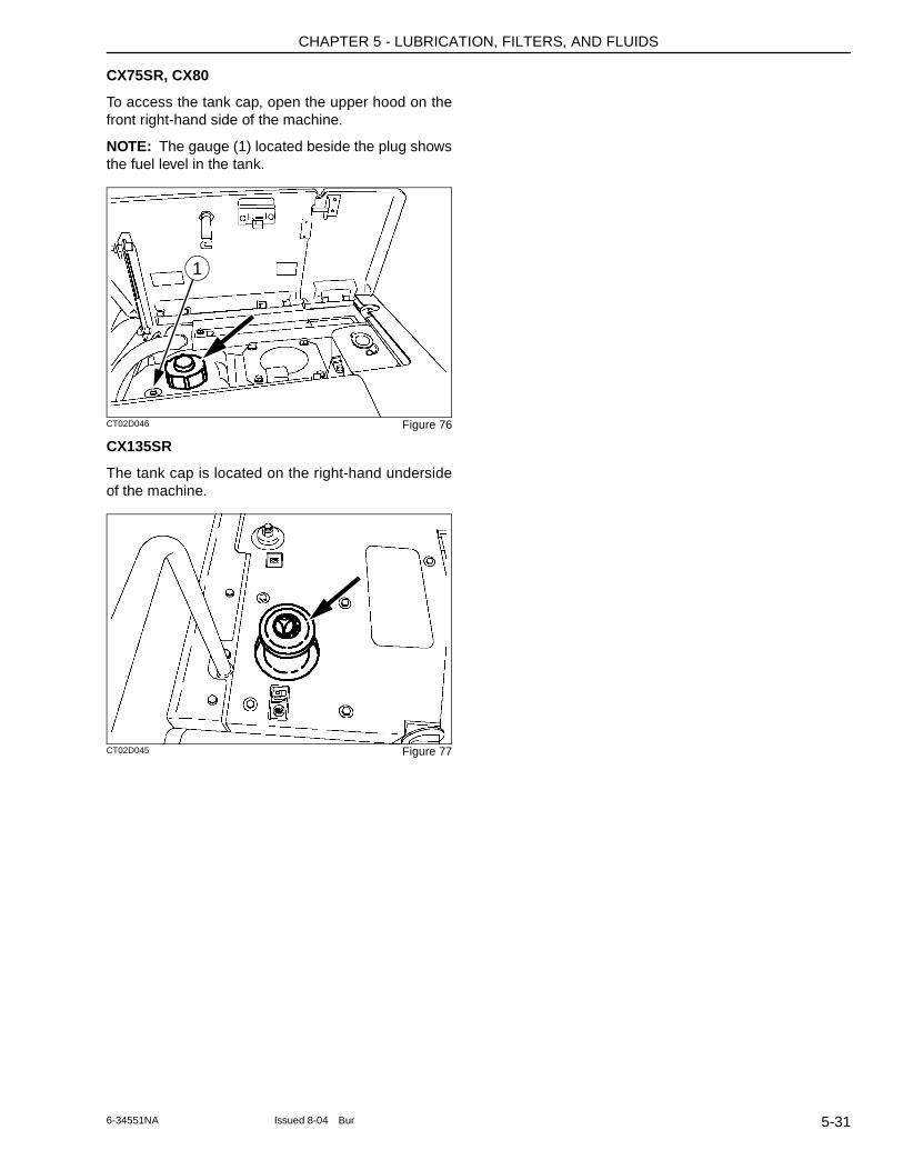
CHAPTER 5 - LUBRICATION, FILTERS, AND FLUIDS
CX75SR, CX80
To access the tank cap, open the upper hood on the front right-hand side of the machine.
NOTE: The gauge (1) located beside the plug shows the fuel level in the tank.
CT02D046 Figure 76
CX135SR
The tank cap is located on the right-hand underside of the machine.
CT02D045 Figure 77
1
5-316-34551NA Issued 8-04 Bur
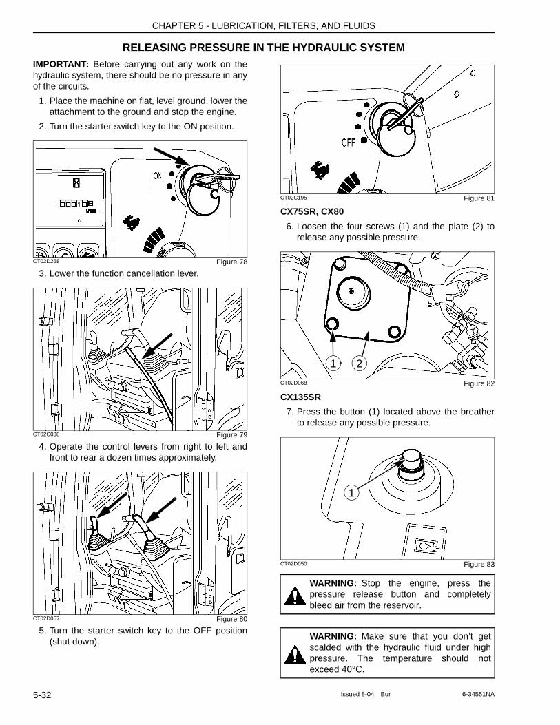
CHAPTER 5 - LUBRICATION, FILTERS, AND FLUIDS
RELEASING PRESSURE IN THE HYDRAULIC SYSTEMIMPORTANT: Before carrying out any work on the hydraulic system, there should be no pressure in any of the circuits.
1. Place the machine on flat, level ground, lower the attachment to the ground and stop the engine.
2. Turn the starter switch key to the ON position.
CT02D268 Figure 78
3. Lower the function cancellation lever.
CT02C038 Figure 79
4. Operate the control levers from right to left and front to rear a dozen times approximately.
CT02D057 Figure 80
5. Turn the starter switch key to the OFF position (shut down).
CT02C195 Figure 81
CX75SR, CX80
6. Loosen the four screws (1) and the plate (2) to release any possible pressure.
CT02D068 Figure 82
CX135SR
7. Press the button (1) located above the breather to release any possible pressure.
CT02D050 Figure 83
WARNING: Stop the engine, press the pressure release button and completely bleed air from the reservoir.
WARNING: Make sure that you don’t get scalded with the hydraulic fluid under high pressure. The temperature should not exceed 40°C.
21
1
5-32 Issued 8-04 Bur 6-34551NA
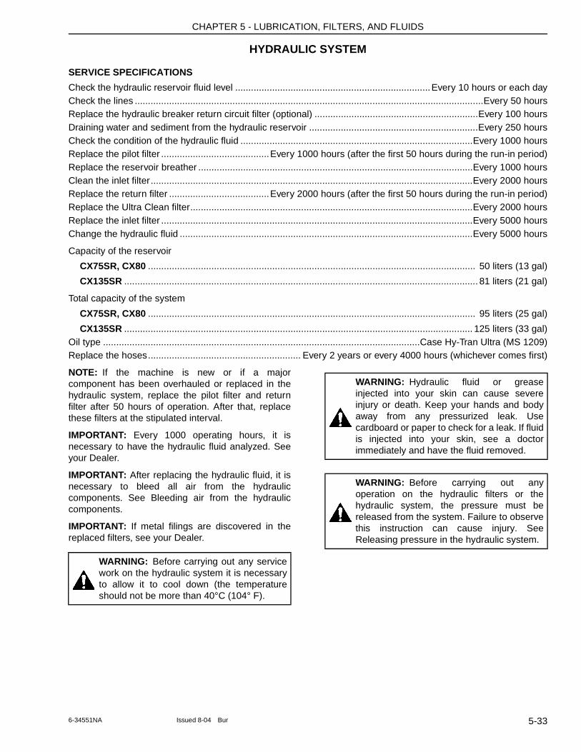
CHAPTER 5 - LUBRICATION, FILTERS, AND FLUIDS
HYDRAULIC SYSTEM
SERVICE SPECIFICATIONS
Check the hydraulic reservoir fluid level ..........................................................................Every 10 hours or each dayCheck the lines ....................................................................................................................................Every 50 hoursReplace the hydraulic breaker return circuit filter (optional) ..............................................................Every 100 hoursDraining water and sediment from the hydraulic reservoir ................................................................Every 250 hoursCheck the condition of the hydraulic fluid ........................................................................................Every 1000 hoursReplace the pilot filter .........................................Every 1000 hours (after the first 50 hours during the run-in period)Replace the reservoir breather ........................................................................................................Every 1000 hoursClean the inlet filter..........................................................................................................................Every 2000 hoursReplace the return filter ......................................Every 2000 hours (after the first 50 hours during the run-in period)Replace the Ultra Clean filter...........................................................................................................Every 2000 hoursReplace the inlet filter ......................................................................................................................Every 5000 hoursChange the hydraulic fluid ...............................................................................................................Every 5000 hours
Capacity of the reservoir
CX75SR, CX80 ............................................................................................................................ 50 liters (13 gal)
CX135SR ...................................................................................................................................... 81 liters (21 gal)
Total capacity of the system
CX75SR, CX80 ............................................................................................................................ 95 liters (25 gal)
CX135SR .................................................................................................................................... 125 liters (33 gal)Oil type ........................................................................................................................Case Hy-Tran Ultra (MS 1209)Replace the hoses.......................................................... Every 2 years or every 4000 hours (whichever comes first)
NOTE: If the machine is new or if a major component has been overhauled or replaced in the hydraulic system, replace the pilot filter and return filter after 50 hours of operation. After that, replace these filters at the stipulated interval.
IMPORTANT: Every 1000 operating hours, it is necessary to have the hydraulic fluid analyzed. See your Dealer.
IMPORTANT: After replacing the hydraulic fluid, it is necessary to bleed all air from the hydraulic components. See Bleeding air from the hydraulic components.
IMPORTANT: If metal filings are discovered in the replaced filters, see your Dealer.
WARNING: Before carrying out any service work on the hydraulic system it is necessary to allow it to cool down (the temperature should not be more than 40°C (104° F).
WARNING: Hydraulic fluid or grease injected into your skin can cause severe injury or death. Keep your hands and body away from any pressurized leak. Use cardboard or paper to check for a leak. If fluid is injected into your skin, see a doctor immediately and have the fluid removed.
WARNING: Before carrying out any operation on the hydraulic filters or the hydraulic system, the pressure must be released from the system. Failure to observe this instruction can cause injury. See Releasing pressure in the hydraulic system.
5-336-34551NA Issued 8-04 Bur
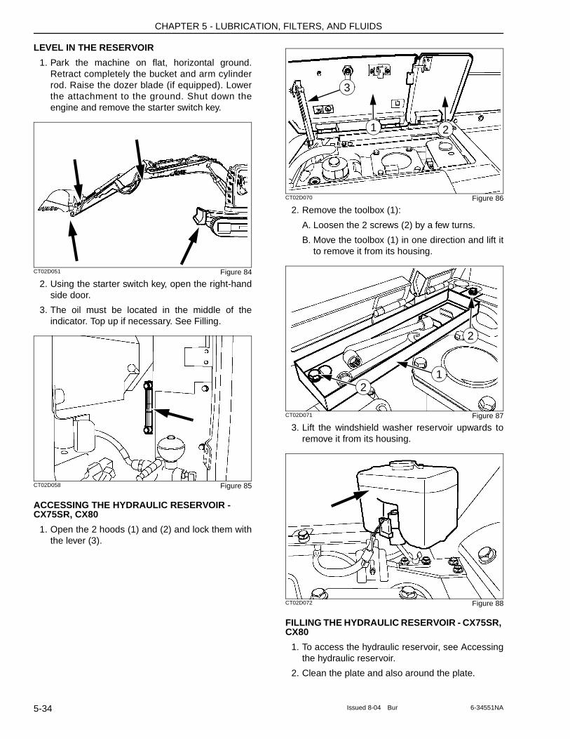
CHAPTER 5 - LUBRICATION, FILTERS, AND FLUIDS
LEVEL IN THE RESERVOIR
1. Park the machine on flat, horizontal ground. Retract completely the bucket and arm cylinder rod. Raise the dozer blade (if equipped). Lower the attachment to the ground. Shut down the engine and remove the starter switch key.
CT02D051 Figure 84
2. Using the starter switch key, open the right-hand side door.
3. The oil must be located in the middle of the indicator. Top up if necessary. See Filling.
CT02D058 Figure 85
ACCESSING THE HYDRAULIC RESERVOIR - CX75SR, CX80
1. Open the 2 hoods (1) and (2) and lock them with the lever (3).
CT02D070 Figure 86
2. Remove the toolbox (1):
A. Loosen the 2 screws (2) by a few turns.
B. Move the toolbox (1) in one direction and lift it to remove it from its housing.
CT02D071 Figure 87
3. Lift the windshield washer reservoir upwards to remove it from its housing.
CT02D072 Figure 88
FILLING THE HYDRAULIC RESERVOIR - CX75SR, CX80
1. To access the hydraulic reservoir, see Accessing the hydraulic reservoir.
2. Clean the plate and also around the plate.
1 2
3
2
2
1
5-34 Issued 8-04 Bur 6-34551NA
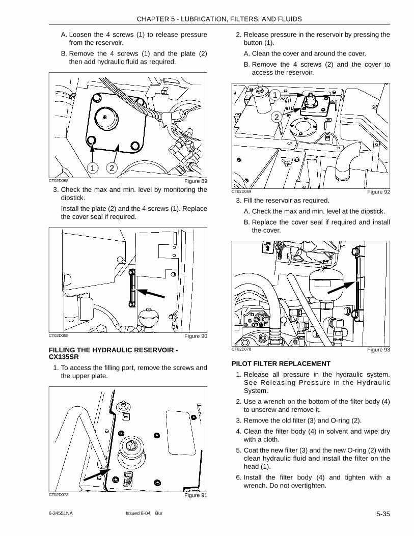
CHAPTER 5 - LUBRICATION, FILTERS, AND FLUIDS
A. Loosen the 4 screws (1) to release pressure from the reservoir.
B. Remove the 4 screws (1) and the plate (2) then add hydraulic fluid as required.
CT02D068 Figure 89
3. Check the max and min. level by monitoring the dipstick.
Install the plate (2) and the 4 screws (1). Replace the cover seal if required.
CT02D058 Figure 90
FILLING THE HYDRAULIC RESERVOIR - CX135SR
1. To access the filling port, remove the screws and the upper plate.
CT02D073 Figure 91
2. Release pressure in the reservoir by pressing the button (1).
A. Clean the cover and around the cover.
B. Remove the 4 screws (2) and the cover to access the reservoir.
CT02D069 Figure 92
3. Fill the reservoir as required.
A. Check the max and min. level at the dipstick.
B. Replace the cover seal if required and install the cover.
CT02D078 Figure 93
PILOT FILTER REPLACEMENT
1. Release all pressure in the hydraulic system. See Releasing Pressure in the Hydraul ic System.
2. Use a wrench on the bottom of the filter body (4) to unscrew and remove it.
3. Remove the old filter (3) and O-ring (2).
4. Clean the filter body (4) in solvent and wipe dry with a cloth.
5. Coat the new filter (3) and the new O-ring (2) with clean hydraulic fluid and install the filter on the head (1).
6. Install the filter body (4) and tighten with a wrench. Do not overtighten.
21
1
2
5-356-34551NA Issued 8-04 Bur
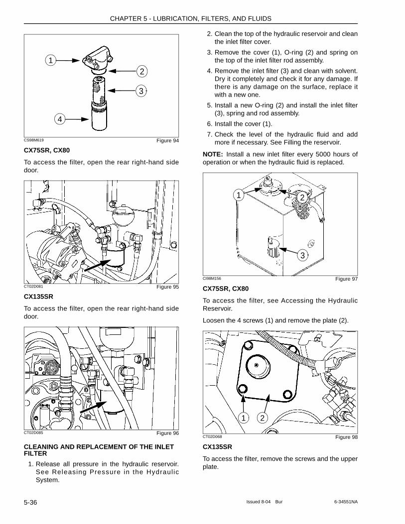
CHAPTER 5 - LUBRICATION, FILTERS, AND FLUIDS
CS98M619 Figure 94
CX75SR, CX80
To access the filter, open the rear right-hand side door.
CT02D081 Figure 95
CX135SR
To access the filter, open the rear right-hand side door.
CT02D085 Figure 96
CLEANING AND REPLACEMENT OF THE INLET FILTER
1. Release all pressure in the hydraulic reservoir. See Releasing Pressure in the Hydraul ic System.
2. Clean the top of the hydraulic reservoir and clean the inlet filter cover.
3. Remove the cover (1), O-ring (2) and spring on the top of the inlet filter rod assembly.
4. Remove the inlet filter (3) and clean with solvent. Dry it completely and check it for any damage. If there is any damage on the surface, replace it with a new one.
5. Install a new O-ring (2) and install the inlet filter (3), spring and rod assembly.
6. Install the cover (1).
7. Check the level of the hydraulic fluid and add more if necessary. See Filling the reservoir.
NOTE: Install a new inlet filter every 5000 hours of operation or when the hydraulic fluid is replaced.
CI98M156 Figure 97
CX75SR, CX80
To access the filter, see Accessing the Hydraulic Reservoir.
Loosen the 4 screws (1) and remove the plate (2).
CT02D068 Figure 98
CX135SR
To access the filter, remove the screws and the upper plate.
1
3
2
4
21
3
21
5-36 Issued 8-04 Bur 6-34551NA
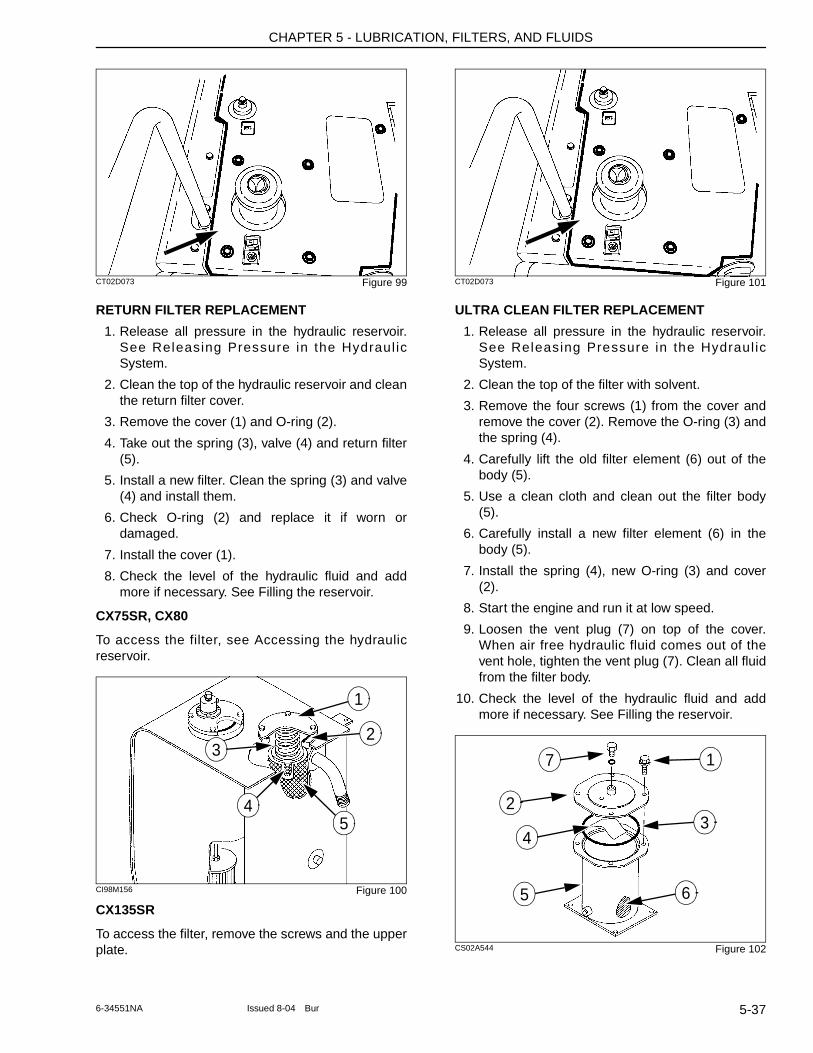
CHAPTER 5 - LUBRICATION, FILTERS, AND FLUIDS
CT02D073 Figure 99
RETURN FILTER REPLACEMENT
1. Release all pressure in the hydraulic reservoir. See Releasing Pressure in the Hydraul ic System.
2. Clean the top of the hydraulic reservoir and clean the return filter cover.
3. Remove the cover (1) and O-ring (2).
4. Take out the spring (3), valve (4) and return filter (5).
5. Install a new filter. Clean the spring (3) and valve (4) and install them.
6. Check O-ring (2) and replace it if worn or damaged.
7. Install the cover (1).
8. Check the level of the hydraulic fluid and add more if necessary. See Filling the reservoir.
CX75SR, CX80
To access the filter, see Accessing the hydraulic reservoir.
CI98M156 Figure 100
CX135SR
To access the filter, remove the screws and the upper plate.
CT02D073 Figure 101
ULTRA CLEAN FILTER REPLACEMENT
1. Release all pressure in the hydraulic reservoir. See Releasing Pressure in the Hydraul ic System.
2. Clean the top of the filter with solvent.
3. Remove the four screws (1) from the cover and remove the cover (2). Remove the O-ring (3) and the spring (4).
4. Carefully lift the old filter element (6) out of the body (5).
5. Use a clean cloth and clean out the filter body (5).
6. Carefully install a new filter element (6) in the body (5).
7. Install the spring (4), new O-ring (3) and cover (2).
8. Start the engine and run it at low speed.
9. Loosen the vent plug (7) on top of the cover. When air free hydraulic fluid comes out of the vent hole, tighten the vent plug (7). Clean all fluid from the filter body.
10. Check the level of the hydraulic fluid and add more if necessary. See Filling the reservoir.
CS02A544 Figure 102
1
3
4
2
5
1
32
4
5 6
7
5-376-34551NA Issued 8-04 Bur
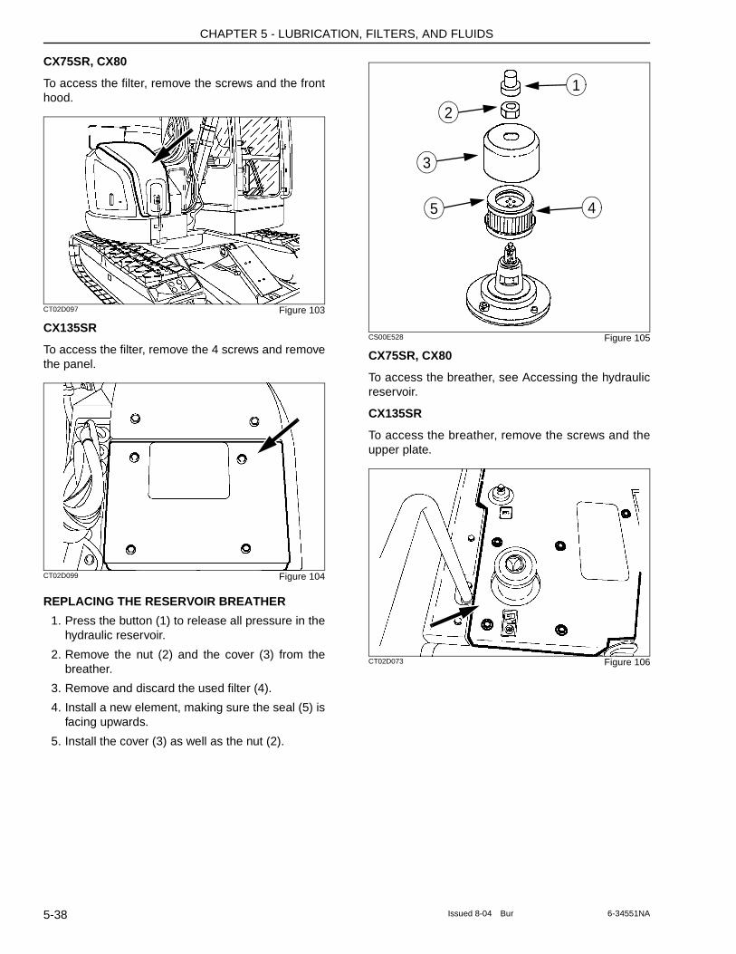
CHAPTER 5 - LUBRICATION, FILTERS, AND FLUIDS
CX75SR, CX80
To access the filter, remove the screws and the front hood.
CT02D097 Figure 103
CX135SR
To access the filter, remove the 4 screws and remove the panel.
CT02D099 Figure 104
REPLACING THE RESERVOIR BREATHER
1. Press the button (1) to release all pressure in the hydraulic reservoir.
2. Remove the nut (2) and the cover (3) from the breather.
3. Remove and discard the used filter (4).
4. Install a new element, making sure the seal (5) is facing upwards.
5. Install the cover (3) as well as the nut (2).
CS00E528 Figure 105
CX75SR, CX80
To access the breather, see Accessing the hydraulic reservoir.
CX135SR
To access the breather, remove the screws and the upper plate.
CT02D073 Figure 106
1
4
3
5
2
5-38 Issued 8-04 Bur 6-34551NA
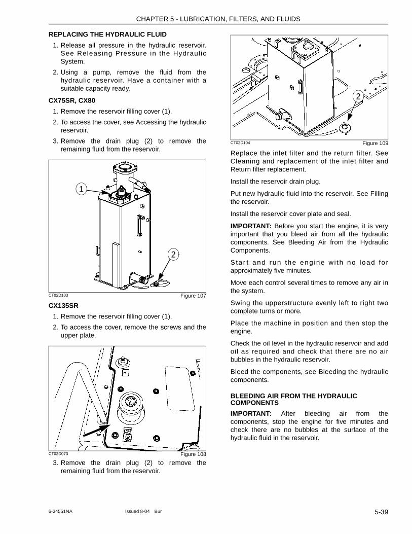
CHAPTER 5 - LUBRICATION, FILTERS, AND FLUIDS
REPLACING THE HYDRAULIC FLUID
1. Release all pressure in the hydraulic reservoir. See Releasing Pressure in the Hydraul ic System.
2. Using a pump, remove the fluid from the hydraulic reservoir. Have a container with a suitable capacity ready.
CX75SR, CX80
1. Remove the reservoir filling cover (1).
2. To access the cover, see Accessing the hydraulic reservoir.
3. Remove the drain plug (2) to remove the remaining fluid from the reservoir.
CT02D103 Figure 107
CX135SR
1. Remove the reservoir filling cover (1).
2. To access the cover, remove the screws and the upper plate.
CT02D073 Figure 108
3. Remove the drain plug (2) to remove the remaining fluid from the reservoir.
CT02D104 Figure 109
Replace the inlet filter and the return filter. See Cleaning and replacement of the inlet filter and Return filter replacement.
Install the reservoir drain plug.
Put new hydraulic fluid into the reservoir. See Filling the reservoir.
Install the reservoir cover plate and seal.
IMPORTANT: Before you start the engine, it is very important that you bleed air from all the hydraulic components. See Bleeding Air from the Hydraulic Components.
Sta r t and run the eng ine w i th no load fo r approximately five minutes.
Move each control several times to remove any air in the system.
Swing the upperstructure evenly left to right two complete turns or more.
Place the machine in position and then stop the engine.
Check the oil level in the hydraulic reservoir and add oil as required and check that there are no air bubbles in the hydraulic reservoir.
Bleed the components, see Bleeding the hydraulic components.
BLEEDING AIR FROM THE HYDRAULIC COMPONENTS
IMPORTANT: After bleeding air from the components, stop the engine for five minutes and check there are no bubbles at the surface of the hydraulic fluid in the reservoir.
1
2
2
5-396-34551NA Issued 8-04 Bur
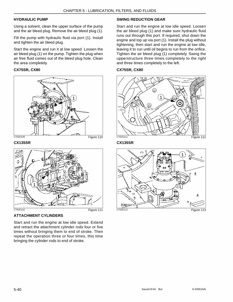
CHAPTER 5 - LUBRICATION, FILTERS, AND FLUIDS
HYDRAULIC PUMP
Using a solvent, clean the upper surface of the pump and the air bleed plug. Remove the air bleed plug (1).
Fill the pump with hydraulic fluid via port (1). Install and tighten the air bleed plug.
Start the engine and run it at low speed. Loosen the air bleed plug (1) on the pump. Tighten the plug when air free fluid comes out of the bleed plug hole. Clean the area completely.
CX75SR, CX80
CT02D109 Figure 110
CX135SR
CT02D110 Figure 111
ATTACHMENT CYLINDERS
Start and run the engine at low idle speed. Extend and retract the attachment cylinder rods four or five times without bringing them to end of stroke. Then repeat the operation three or four times, this time bringing the cylinder rods to end of stroke.
SWING REDUCTION GEAR
Start and run the engine at low idle speed. Loosen the air bleed plug (1) and make sure hydraulic fluid runs out through this port. If required, shut down the engine and top up via port (1). Install the plug without tightening, then start and run the engine at low idle, leaving it to run until oil begins to run from the orifice. Tighten the air bleed plug (1) completely. Swing the upperstructure three times completely to the right and three times completely to the left.
CX75SR, CX80
CT02D111 Figure 112
CX135SR
CT02D112 Figure 113
1
1
1
1
5-40 Issued 8-04 Bur 6-34551NA
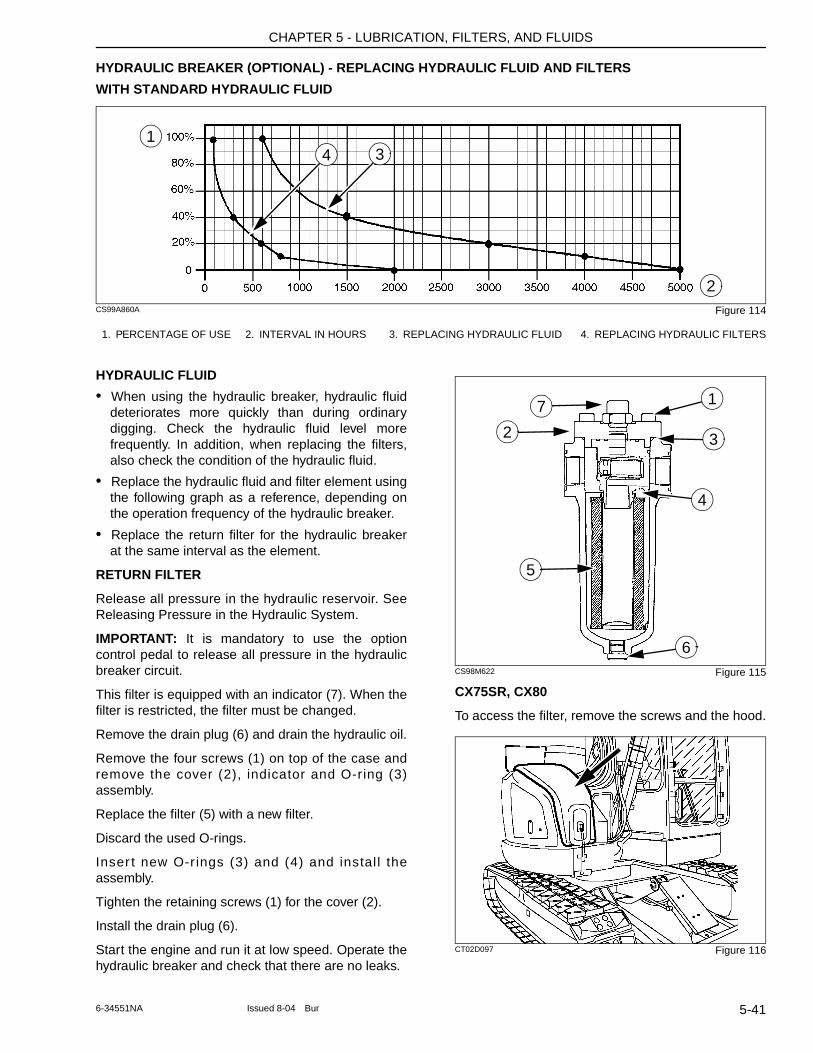
CHAPTER 5 - LUBRICATION, FILTERS, AND FLUIDS
HYDRAULIC BREAKER (OPTIONAL) - REPLACING HYDRAULIC FLUID AND FILTERS
WITH STANDARD HYDRAULIC FLUID
CS99A860A Figure 114
HYDRAULIC FLUID
• When using the hydraulic breaker, hydraulic fluid deteriorates more quickly than during ordinary digging. Check the hydraulic fluid level more frequently. In addition, when replacing the filters, also check the condition of the hydraulic fluid.
• Replace the hydraulic fluid and filter element using the following graph as a reference, depending on the operation frequency of the hydraulic breaker.
• Replace the return filter for the hydraulic breaker at the same interval as the element.
RETURN FILTER
Release all pressure in the hydraulic reservoir. See Releasing Pressure in the Hydraulic System.
IMPORTANT: It is mandatory to use the option control pedal to release all pressure in the hydraulic breaker circuit.
This filter is equipped with an indicator (7). When the filter is restricted, the filter must be changed.
Remove the drain plug (6) and drain the hydraulic oil.
Remove the four screws (1) on top of the case and remove the cover (2), indicator and O-ring (3) assembly.
Replace the filter (5) with a new filter.
Discard the used O-rings.
Inser t new O-r ings (3) and (4) and instal l the assembly.
Tighten the retaining screws (1) for the cover (2).
Install the drain plug (6).
Start the engine and run it at low speed. Operate the hydraulic breaker and check that there are no leaks.
CS98M622 Figure 115
CX75SR, CX80
To access the filter, remove the screws and the hood.
CT02D097 Figure 116
1. PERCENTAGE OF USE 2. INTERVAL IN HOURS 3. REPLACING HYDRAULIC FLUID 4. REPLACING HYDRAULIC FILTERS
4 31
2
17
2
6
5
4
3
5-416-34551NA Issued 8-04 Bur
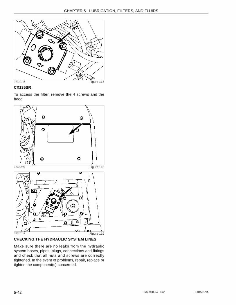
CHAPTER 5 - LUBRICATION, FILTERS, AND FLUIDS
CT02D113 Figure 117
CX135SR
To access the filter, remove the 4 screws and the hood.
CT02D099 Figure 118
CT02D114 Figure 119
CHECKING THE HYDRAULIC SYSTEM LINES
Make sure there are no leaks from the hydraulic system hoses, pipes, plugs, connections and fittings and check that all nuts and screws are correctly tightened. In the event of problems, repair, replace or tighten the component(s) concerned.
5-42 Issued 8-04 Bur 6-34551NA
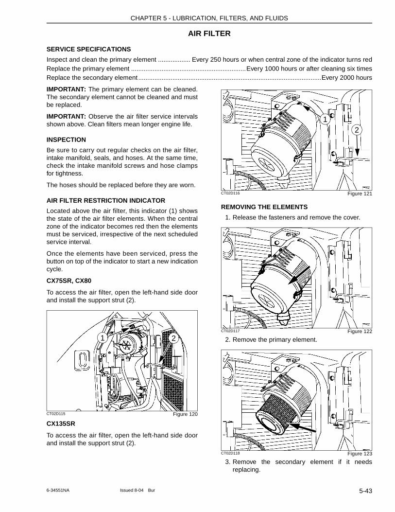
CHAPTER 5 - LUBRICATION, FILTERS, AND FLUIDS
AIR FILTER
SERVICE SPECIFICATIONS
Inspect and clean the primary element .................. Every 250 hours or when central zone of the indicator turns redReplace the primary element ................................................................Every 1000 hours or after cleaning six timesReplace the secondary element ......................................................................................................Every 2000 hours
IMPORTANT: The primary element can be cleaned. The secondary element cannot be cleaned and must be replaced.
IMPORTANT: Observe the air filter service intervals shown above. Clean filters mean longer engine life.
INSPECTION
Be sure to carry out regular checks on the air filter, intake manifold, seals, and hoses. At the same time, check the intake manifold screws and hose clamps for tightness.
The hoses should be replaced before they are worn.
AIR FILTER RESTRICTION INDICATOR
Located above the air filter, this indicator (1) shows the state of the air filter elements. When the central zone of the indicator becomes red then the elements must be serviced, irrespective of the next scheduled service interval.
Once the elements have been serviced, press the button on top of the indicator to start a new indication cycle.
CX75SR, CX80
To access the air filter, open the left-hand side door and install the support strut (2).
CT02D115 Figure 120
CX135SR
To access the air filter, open the left-hand side door and install the support strut (2).
CT02D116 Figure 121
REMOVING THE ELEMENTS
1. Release the fasteners and remove the cover.
CT02D117 Figure 122
2. Remove the primary element.
CT02D118 Figure 123
3. Remove the secondary element if it needs replacing.
21
21
5-436-34551NA Issued 8-04 Bur
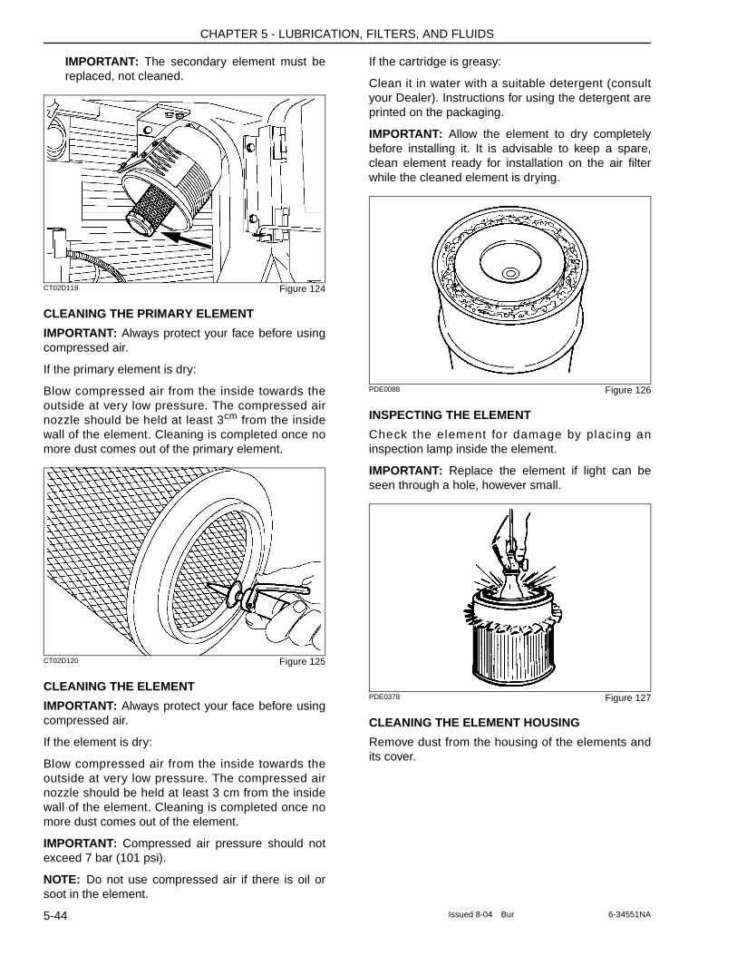
CHAPTER 5 - LUBRICATION, FILTERS, AND FLUIDS
IMPORTANT: The secondary element must be replaced, not cleaned.
CT02D119 Figure 124
CLEANING THE PRIMARY ELEMENT
IMPORTANT: Always protect your face before using compressed air.
If the primary element is dry:
Blow compressed air from the inside towards the outside at very low pressure. The compressed air nozzle should be held at least 3cm from the inside wall of the element. Cleaning is completed once no more dust comes out of the primary element.
CT02D120 Figure 125
CLEANING THE ELEMENT
IMPORTANT: Always protect your face before using compressed air.
If the element is dry:
Blow compressed air from the inside towards the outside at very low pressure. The compressed air nozzle should be held at least 3 cm from the inside wall of the element. Cleaning is completed once no more dust comes out of the element.
IMPORTANT: Compressed air pressure should not exceed 7 bar (101 psi).
NOTE: Do not use compressed air if there is oil or soot in the element.
If the cartridge is greasy:
Clean it in water with a suitable detergent (consult your Dealer). Instructions for using the detergent are printed on the packaging.
IMPORTANT: Allow the element to dry completely before installing it. It is advisable to keep a spare, clean element ready for installation on the air filter while the cleaned element is drying.
PDE0088 Figure 126
INSPECTING THE ELEMENT
Check the element for damage by placing an inspection lamp inside the element.
IMPORTANT: Replace the element if light can be seen through a hole, however small.
PDE0378 Figure 127
CLEANING THE ELEMENT HOUSING
Remove dust from the housing of the elements and its cover.
5-44 Issued 8-04 Bur 6-34551NA
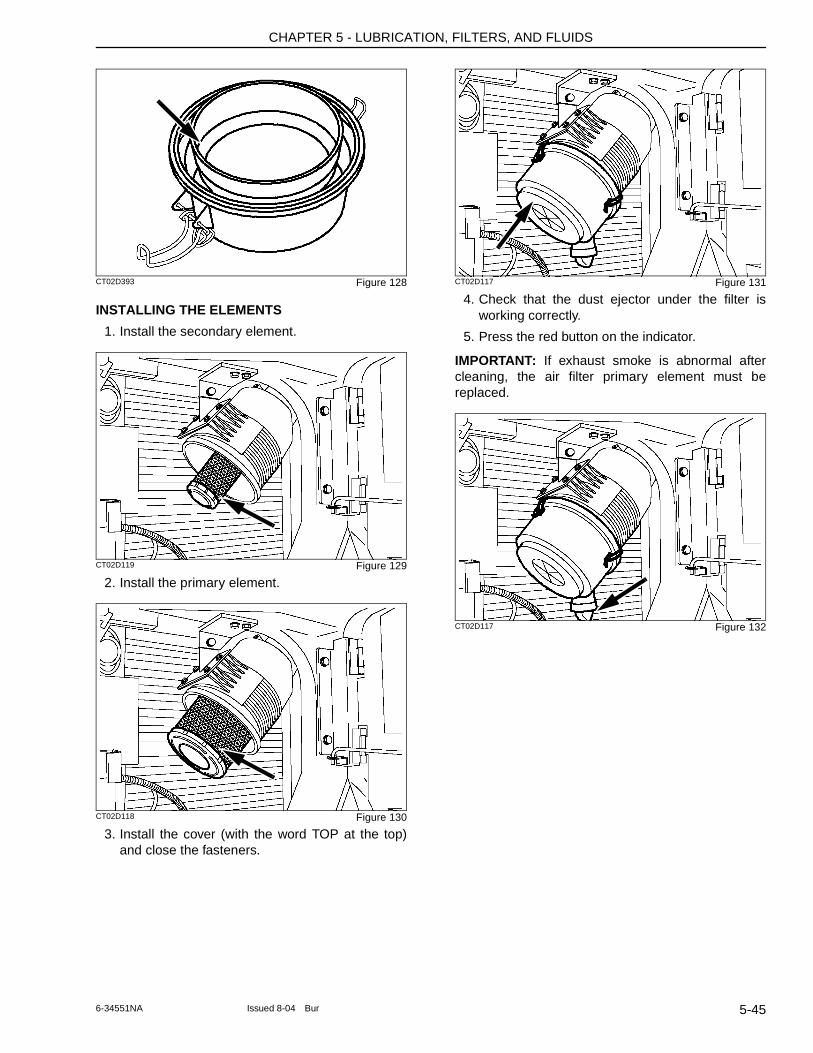
CHAPTER 5 - LUBRICATION, FILTERS, AND FLUIDS
CT02D393 Figure 128
INSTALLING THE ELEMENTS
1. Install the secondary element.
CT02D119 Figure 129
2. Install the primary element.
CT02D118 Figure 130
3. Install the cover (with the word TOP at the top) and close the fasteners.
CT02D117 Figure 131
4. Check that the dust ejector under the filter is working correctly.
5. Press the red button on the indicator.
IMPORTANT: If exhaust smoke is abnormal after cleaning, the air filter primary element must be replaced.
CT02D117 Figure 132
5-456-34551NA Issued 8-04 Bur
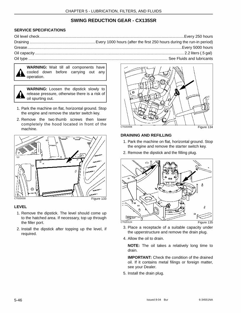
CHAPTER 5 - LUBRICATION, FILTERS, AND FLUIDS
SWING REDUCTION GEAR - CX135SR
SERVICE SPECIFICATIONS
Oil level check....................................................................................................................................Every 250 hoursDraining ............................................................Every 1000 hours (after the first 250 hours during the run-in period)Grease.............................................................................................................................................Every 5000 hoursOil capacity ........................................................................................................................................ 2.2 liters (.5 gal) Oil type ............................................................................................................................... See Fluids and lubricants
1. Park the machine on flat, horizontal ground. Stop the engine and remove the starter switch key.
2. Remove the two thumb screws then lower completely the hood located in front of the machine.
CT02D030 Figure 133
LEVEL
1. Remove the dipstick. The level should come up to the hatched area. If necessary, top up through the filler port.
2. Install the dipstick after topping up the level, if required.
CT02D008 Figure 134
DRAINING AND REFILLING
1. Park the machine on flat, horizontal ground. Stop the engine and remove the starter switch key.
2. Remove the dipstick and the filling plug.
CT02D124 Figure 135
3. Place a receptacle of a suitable capacity under the upperstructure and remove the drain plug.
4. Allow the oil to drain.
NOTE: The oil takes a relatively long time to drain.
IMPORTANT: Check the condition of the drained oil. If it contains metal filings or foreign matter, see your Dealer.
5. Install the drain plug.
WARNING: Wait till all components have cooled down before carrying out any operation.
WARNING: Loosen the dipstick slowly to release pressure, otherwise there is a risk of oil spurting out.
5-46 Issued 8-04 Bur 6-34551NA
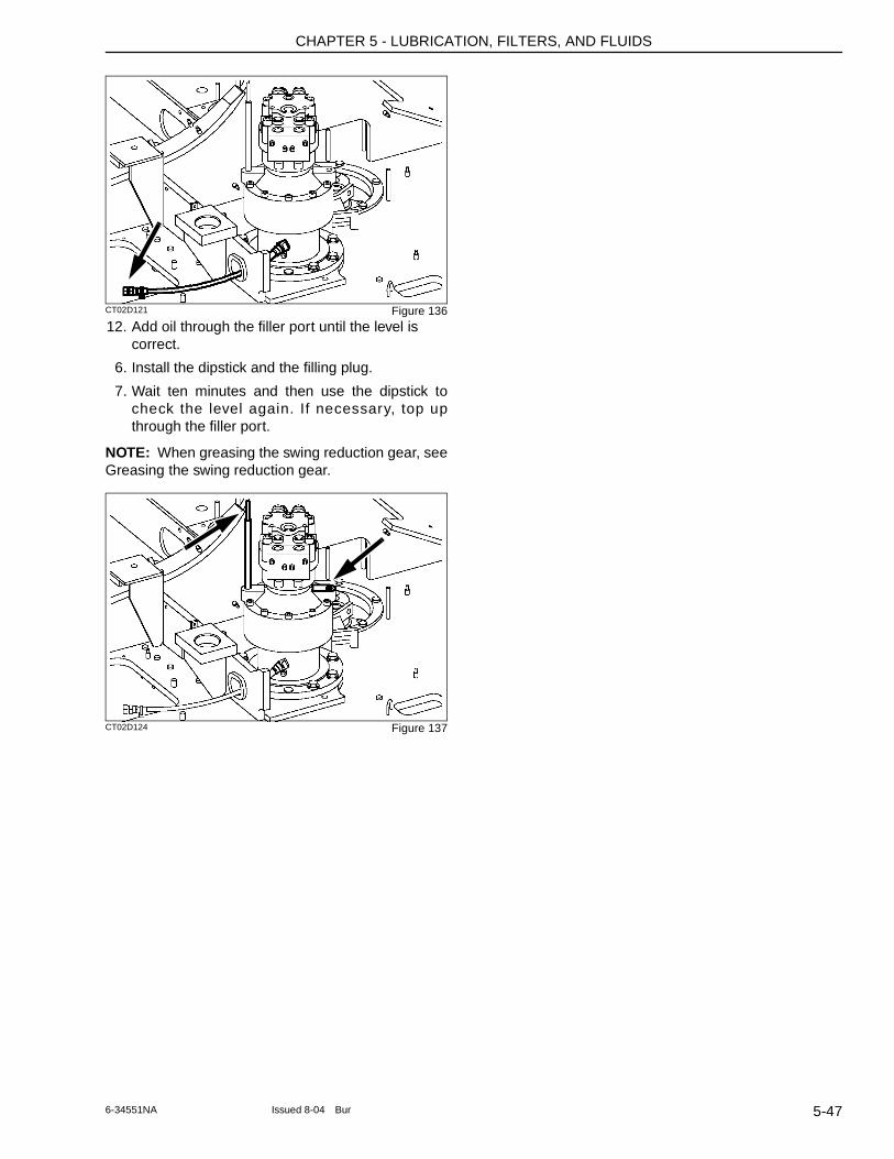
CHAPTER 5 - LUBRICATION, FILTERS, AND FLUIDS
CT02D121 Figure 13612. Add oil through the filler port until the level is
correct.
6. Install the dipstick and the filling plug.
7. Wait ten minutes and then use the dipstick to check the level again. If necessary, top up through the filler port.
NOTE: When greasing the swing reduction gear, see Greasing the swing reduction gear.
CT02D124 Figure 137
5-476-34551NA Issued 8-04 Bur
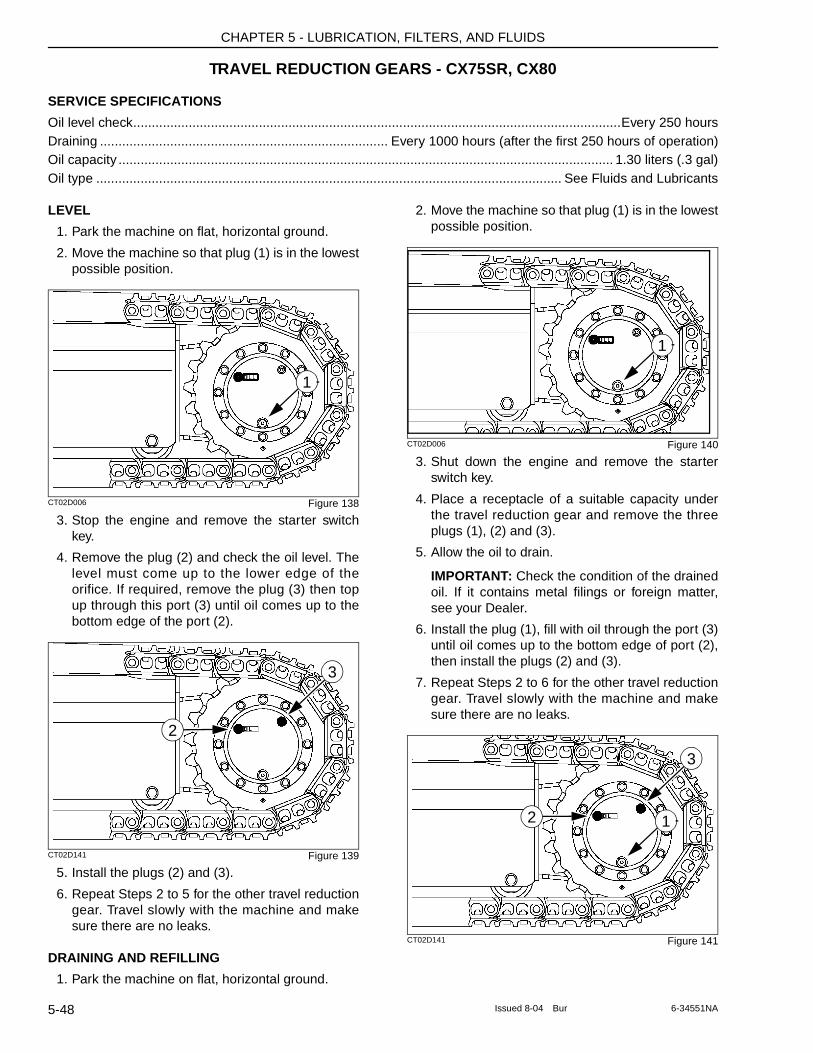
CHAPTER 5 - LUBRICATION, FILTERS, AND FLUIDS
TRAVEL REDUCTION GEARS - CX75SR, CX80
SERVICE SPECIFICATIONS
Oil level check....................................................................................................................................Every 250 hoursDraining .............................................................................. Every 1000 hours (after the first 250 hours of operation)Oil capacity ...................................................................................................................................... 1.30 liters (.3 gal)Oil type .............................................................................................................................. See Fluids and Lubricants
LEVEL
1. Park the machine on flat, horizontal ground.
2. Move the machine so that plug (1) is in the lowest possible position.
CT02D006 Figure 138
3. Stop the engine and remove the starter switch key.
4. Remove the plug (2) and check the oil level. The level must come up to the lower edge of the orifice. If required, remove the plug (3) then top up through this port (3) until oil comes up to the bottom edge of the port (2).
CT02D141 Figure 139
5. Install the plugs (2) and (3).
6. Repeat Steps 2 to 5 for the other travel reduction gear. Travel slowly with the machine and make sure there are no leaks.
DRAINING AND REFILLING
1. Park the machine on flat, horizontal ground.
2. Move the machine so that plug (1) is in the lowest possible position.
CT02D006 Figure 140
3. Shut down the engine and remove the starter switch key.
4. Place a receptacle of a suitable capacity under the travel reduction gear and remove the three plugs (1), (2) and (3).
5. Allow the oil to drain.
IMPORTANT: Check the condition of the drained oil. If it contains metal filings or foreign matter, see your Dealer.
6. Install the plug (1), fill with oil through the port (3) until oil comes up to the bottom edge of port (2), then install the plugs (2) and (3).
7. Repeat Steps 2 to 6 for the other travel reduction gear. Travel slowly with the machine and make sure there are no leaks.
CT02D141 Figure 141
1
2
3
1
12
3
5-48 Issued 8-04 Bur 6-34551NA
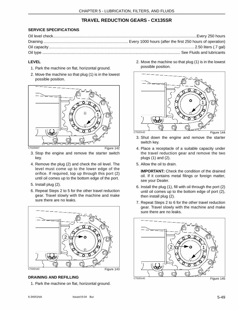
CHAPTER 5 - LUBRICATION, FILTERS, AND FLUIDS
TRAVEL REDUCTION GEARS - CX135SR
SERVICE SPECIFICATIONS
Oil level check....................................................................................................................................Every 250 hoursDraining .............................................................................. Every 1000 hours (after the first 250 hours of operation)Oil capacity ...................................................................................................................................... 2.50 liters (.7 gal)Oil type ............................................................................................................................... See Fluids and lubricants
LEVEL
1. Park the machine on flat, horizontal ground.
2. Move the machine so that plug (1) is in the lowest possible position.
CT02D007 Figure 142
3. Stop the engine and remove the starter switch key.
4. Remove the plug (2) and check the oil level. The level must come up to the lower edge of the orifice. If required, top up through this port (2) until oil comes up to the bottom edge of the port.
5. Install plug (2).
6. Repeat Steps 2 to 5 for the other travel reduction gear. Travel slowly with the machine and make sure there are no leaks.
CT02D142 Figure 143
DRAINING AND REFILLING
1. Park the machine on flat, horizontal ground.
2. Move the machine so that plug (1) is in the lowest possible position.
CT02D142 Figure 144
3. Shut down the engine and remove the starter switch key.
4. Place a receptacle of a suitable capacity under the travel reduction gear and remove the two plugs (1) and (2).
5. Allow the oil to drain.
IMPORTANT: Check the condition of the drained oil. If it contains metal filings or foreign matter, see your Dealer.
6. Install the plug (1), fill with oil through the port (2) until oil comes up to the bottom edge of port (2), then install plug (2).
7. Repeat Steps 2 to 6 for the other travel reduction gear. Travel slowly with the machine and make sure there are no leaks.
CT02D142 Figure 145
1
2
1
2 1
5-496-34551NA Issued 8-04 Bur

CHAPTER 5 - LUBRICATION, FILTERS, AND FLUIDS
NOTES
5-50 Issued 8-04 Bur 6-34551NA
CHAPTER 6 - MAINTENANCE AND ADJUSTMENTS
Chapter 6
MAINTENANCE AND ADJUSTMENTS
TABLE OF CONTENTS
TRACKS . . . . . . . . . . . . . . . . . . . . . . . . . . . . . . . . . . . . . . . . . . . . . . . . . . . . . . . . . . . . . . . . . . . . . . . . . . . . . . . . 6-3Maintenance Specifications . . . . . . . . . . . . . . . . . . . . . . . . . . . . . . . . . . . . . . . . . . . . . . . . . . . . . . . . . . . . . . . 6-3Cleaning . . . . . . . . . . . . . . . . . . . . . . . . . . . . . . . . . . . . . . . . . . . . . . . . . . . . . . . . . . . . . . . . . . . . . . . . . . . . . . 6-3Checking the Tension . . . . . . . . . . . . . . . . . . . . . . . . . . . . . . . . . . . . . . . . . . . . . . . . . . . . . . . . . . . . . . . . . . . 6-3Adjusting the Tension . . . . . . . . . . . . . . . . . . . . . . . . . . . . . . . . . . . . . . . . . . . . . . . . . . . . . . . . . . . . . . . . . . . . 6-4To Reduce Tension . . . . . . . . . . . . . . . . . . . . . . . . . . . . . . . . . . . . . . . . . . . . . . . . . . . . . . . . . . . . . . . . . . . . . 6-4
CHECKING THE CONDITION OF RUBBER TRACKS (IF EQUIPPED) . . . . . . . . . . . . . . . . . . . . . . . . . . . . . . . 6-6
REPLACING THE RUBBER TRACKS (CX75SR, CX80 IF EQUIPPED) . . . . . . . . . . . . . . . . . . . . . . . . . . . . . . . 6-6Removal . . . . . . . . . . . . . . . . . . . . . . . . . . . . . . . . . . . . . . . . . . . . . . . . . . . . . . . . . . . . . . . . . . . . . . . . . . . . . . 6-6Installation . . . . . . . . . . . . . . . . . . . . . . . . . . . . . . . . . . . . . . . . . . . . . . . . . . . . . . . . . . . . . . . . . . . . . . . . . . . . 6-7
TRACK ROLLERS AND IDLER WHEELS . . . . . . . . . . . . . . . . . . . . . . . . . . . . . . . . . . . . . . . . . . . . . . . . . . . . . . 6-8Maintenance Specification . . . . . . . . . . . . . . . . . . . . . . . . . . . . . . . . . . . . . . . . . . . . . . . . . . . . . . . . . . . . . . . . 6-8
RADIATOR AND OIL COOLER . . . . . . . . . . . . . . . . . . . . . . . . . . . . . . . . . . . . . . . . . . . . . . . . . . . . . . . . . . . . . . 6-9Maintenance Specifications . . . . . . . . . . . . . . . . . . . . . . . . . . . . . . . . . . . . . . . . . . . . . . . . . . . . . . . . . . . . . . . 6-9Cleaning . . . . . . . . . . . . . . . . . . . . . . . . . . . . . . . . . . . . . . . . . . . . . . . . . . . . . . . . . . . . . . . . . . . . . . . . . . . . . . 6-9
FAN AND ALTERNATOR DRIVE BELT . . . . . . . . . . . . . . . . . . . . . . . . . . . . . . . . . . . . . . . . . . . . . . . . . . . . . . . 6-10Maintenance Specifications . . . . . . . . . . . . . . . . . . . . . . . . . . . . . . . . . . . . . . . . . . . . . . . . . . . . . . . . . . . . . . 6-10Checking the Tension . . . . . . . . . . . . . . . . . . . . . . . . . . . . . . . . . . . . . . . . . . . . . . . . . . . . . . . . . . . . . . . . . . 6-10Adjusting the Tension . . . . . . . . . . . . . . . . . . . . . . . . . . . . . . . . . . . . . . . . . . . . . . . . . . . . . . . . . . . . . . . . . . . 6-10Replacing the Belt . . . . . . . . . . . . . . . . . . . . . . . . . . . . . . . . . . . . . . . . . . . . . . . . . . . . . . . . . . . . . . . . . . . . . 6-10
FUEL TANK FILTER . . . . . . . . . . . . . . . . . . . . . . . . . . . . . . . . . . . . . . . . . . . . . . . . . . . . . . . . . . . . . . . . . . . . . 6-12Maintenance Specification . . . . . . . . . . . . . . . . . . . . . . . . . . . . . . . . . . . . . . . . . . . . . . . . . . . . . . . . . . . . . . . 6-12
INSPECTING AND CLEANING THE MACHINE . . . . . . . . . . . . . . . . . . . . . . . . . . . . . . . . . . . . . . . . . . . . . . . . 6-12Maintenance Specifications . . . . . . . . . . . . . . . . . . . . . . . . . . . . . . . . . . . . . . . . . . . . . . . . . . . . . . . . . . . . . . 6-12
CHECKING FOR CYLINDER LEAKAGE . . . . . . . . . . . . . . . . . . . . . . . . . . . . . . . . . . . . . . . . . . . . . . . . . . . . . . 6-12
REPLACING A BUCKET - CX75SR, CX80 . . . . . . . . . . . . . . . . . . . . . . . . . . . . . . . . . . . . . . . . . . . . . . . . . . . . 6-13Removal . . . . . . . . . . . . . . . . . . . . . . . . . . . . . . . . . . . . . . . . . . . . . . . . . . . . . . . . . . . . . . . . . . . . . . . . . . . . . 6-13Installation . . . . . . . . . . . . . . . . . . . . . . . . . . . . . . . . . . . . . . . . . . . . . . . . . . . . . . . . . . . . . . . . . . . . . . . . . . . 6-13
REPLACING A BUCKET - CX135SR . . . . . . . . . . . . . . . . . . . . . . . . . . . . . . . . . . . . . . . . . . . . . . . . . . . . . . . . . 6-14Removal . . . . . . . . . . . . . . . . . . . . . . . . . . . . . . . . . . . . . . . . . . . . . . . . . . . . . . . . . . . . . . . . . . . . . . . . . . . . . 6-14Installation . . . . . . . . . . . . . . . . . . . . . . . . . . . . . . . . . . . . . . . . . . . . . . . . . . . . . . . . . . . . . . . . . . . . . . . . . . . 6-14
FIRE EXTINGUISHER (NOT SUPPLIED) . . . . . . . . . . . . . . . . . . . . . . . . . . . . . . . . . . . . . . . . . . . . . . . . . . . . . 6-15
WELDING ON THE MACHINE . . . . . . . . . . . . . . . . . . . . . . . . . . . . . . . . . . . . . . . . . . . . . . . . . . . . . . . . . . . . . . 6-15
PLASTIC AND RESIN PARTS . . . . . . . . . . . . . . . . . . . . . . . . . . . . . . . . . . . . . . . . . . . . . . . . . . . . . . . . . . . . . . 6-15
AIR CONDITIONING . . . . . . . . . . . . . . . . . . . . . . . . . . . . . . . . . . . . . . . . . . . . . . . . . . . . . . . . . . . . . . . . . . . . . 6-16MAINTENANCE SPECIFICATION . . . . . . . . . . . . . . . . . . . . . . . . . . . . . . . . . . . . . . . . . . . . . . . . . . . . . . . . . 6-16
HARDWARE TORQUE INSPECTION . . . . . . . . . . . . . . . . . . . . . . . . . . . . . . . . . . . . . . . . . . . . . . . . . . . . . . . . 6-18MAINTENANCE SPECIFICATION . . . . . . . . . . . . . . . . . . . . . . . . . . . . . . . . . . . . . . . . . . . . . . . . . . . . . . . . . 6-18(CX135SR) . . . . . . . . . . . . . . . . . . . . . . . . . . . . . . . . . . . . . . . . . . . . . . . . . . . . . . . . . . . . . . . . . . . . . . . . . . . 6-19
6-1Issued 8-04 Bur 6-34551NA

CHAPTER 6 - MAINTENANCE AND ADJUSTMENTS
6-2 Issued 8-04 Bur 6-34551NA
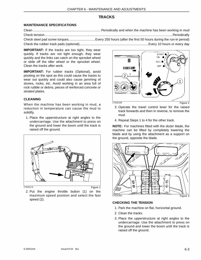
CHAPTER 6 - MAINTENANCE AND ADJUSTMENTS
TRACKS
MAINTENANCE SPECIFICATIONS
Clean .......................................................................... Periodically and when the machine has been working in mudCheck tension............................................................................................................................................PeriodicallyCheck steel pad screw torques.............................Every 250 hours (after the first 50 hours during the run-in period)Check the rubber track pads (optional)........................................................................... Every 10 hours or every day
IMPORTANT: If the tracks are too tight, they wear quickly. If tracks are not tight enough, they wear quickly and the links can catch on the sprocket wheel or slide off the idler wheel or the sprocket wheel. Clean the tracks after work.
IMPORTANT: For rubber tracks (Optional), avoid pivoting on the spot as this could cause the tracks to wear out quickly and could also cause jamming of stones, rocks, etc. Avoid working in an area full of rock rubble or debris, pieces of reinforced concrete or striated plates.
CLEANING
When the machine has been working in mud, a reduction in temperature can cause the mud to solidify.
1. Place the upperstructure at right angles to the undercarriage. Use the attachment to press on the ground and lower the boom until the track is raised off the ground.
CT02D176 Figure 1
2. Put the engine throttle button (1) on the maximum speed position and select the fast speed (2).
CT02D156 Figure 2
3. Operate the travel control lever for the raised track forwards and then in reverse, to remove the mud.
4. Repeat Steps 1 to 4 for the other track.
NOTE: For machines fitted with the dozer blade, the machine can be lifted by completely lowering the blade and by using the attachment as a support on the ground, opposite the blade.
CT02C063 Figure 3
CHECKING THE TENSION
1. Park the machine on flat, horizontal ground.
2. Clean the tracks.
3. Place the upperstructure at right angles to the undercarriage. Use the attachment to press on the ground and lower the boom until the track is raised off the ground.
12
6-36-34551NA Issued 8-04 Bur
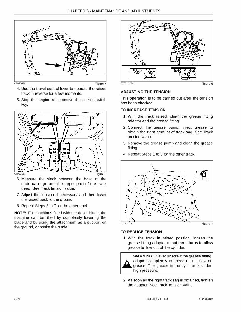
CHAPTER 6 - MAINTENANCE AND ADJUSTMENTS
CT02D176 Figure 4
4. Use the travel control lever to operate the raised track in reverse for a few moments.
5. Stop the engine and remove the starter switch key.
CT02C063 Figure 5
6. Measure the slack between the base of the undercarriage and the upper part of the track tread. See Track tension value.
7. Adjust the tension if necessary and then lower the raised track to the ground.
8. Repeat Steps 3 to 7 for the other track.
NOTE: For machines fitted with the dozer blade, the machine can be lifted by completely lowering the blade and by using the attachment as a support on the ground, opposite the blade.
CT02D176A Figure 6
ADJUSTING THE TENSION
This operation is to be carried out after the tension has been checked.
TO INCREASE TENSION
1. With the track raised, clean the grease fitting adaptor and the grease fitting.
2. Connect the grease pump. Inject grease to obtain the right amount of track sag. See Track tension value.
3. Remove the grease pump and clean the grease fitting.
4. Repeat Steps 1 to 3 for the other track.
CT02D177 Figure 7
TO REDUCE TENSION
1. With the track in raised position, loosen the grease fitting adaptor about three turns to allow grease to flow out of the cylinder.
2. As soon as the right track sag is obtained, tighten the adaptor. See Track Tension Value.
WARNING: Never unscrew the grease fitting adaptor completely to speed up the flow of grease. The grease in the cylinder is under high pressure.
6-4 Issued 8-04 Bur 6-34551NA
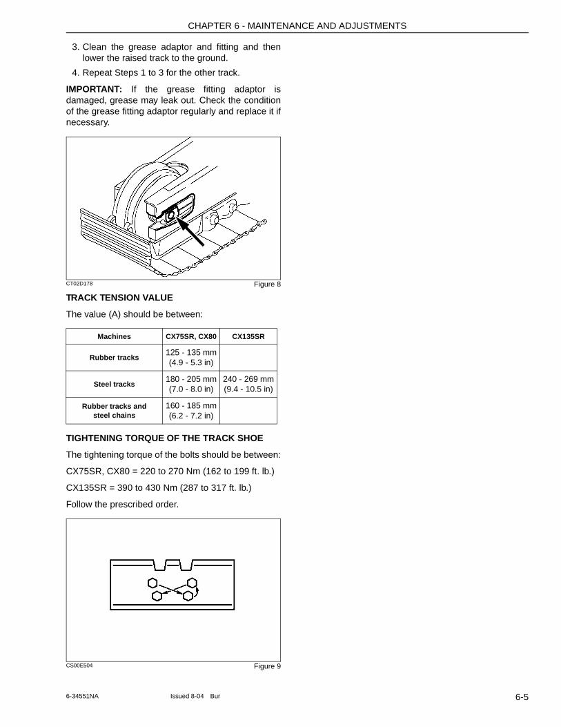
CHAPTER 6 - MAINTENANCE AND ADJUSTMENTS
3. Clean the grease adaptor and fitting and then lower the raised track to the ground.
4. Repeat Steps 1 to 3 for the other track.
IMPORTANT: If the grease fitting adaptor is damaged, grease may leak out. Check the condition of the grease fitting adaptor regularly and replace it if necessary.
CT02D178 Figure 8
TRACK TENSION VALUE
The value (A) should be between:
TIGHTENING TORQUE OF THE TRACK SHOE
The tightening torque of the bolts should be between:
CX75SR, CX80 = 220 to 270 Nm (162 to 199 ft. lb.)
CX135SR = 390 to 430 Nm (287 to 317 ft. lb.)
Follow the prescribed order.
CS00E504 Figure 9
Machines CX75SR, CX80 CX135SR
Rubber tracks125 - 135 mm (4.9 - 5.3 in)
Steel tracks180 - 205 mm (7.0 - 8.0 in)
240 - 269 mm (9.4 - 10.5 in)
Rubber tracks and steel chains
160 - 185 mm (6.2 - 7.2 in)
6-56-34551NA Issued 8-04 Bur
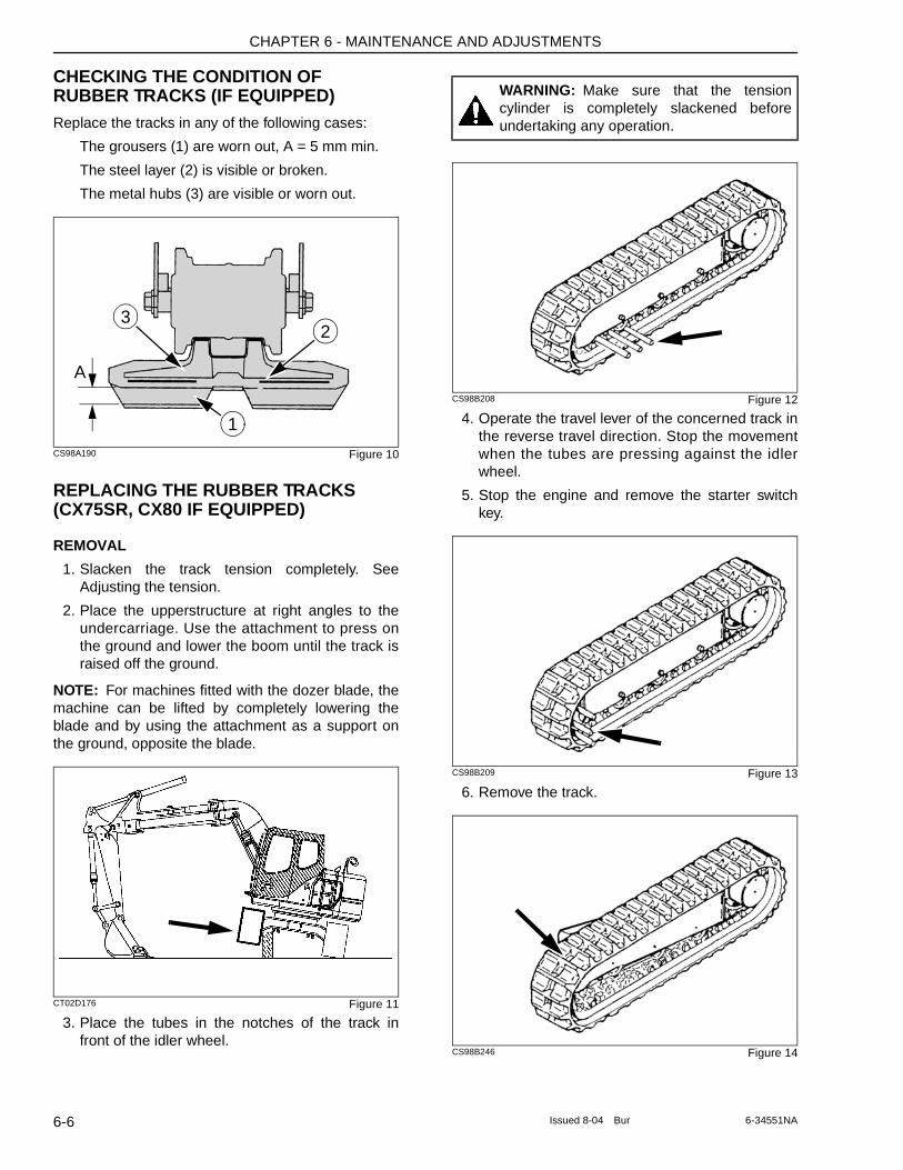
CHAPTER 6 - MAINTENANCE AND ADJUSTMENTS
CHECKING THE CONDITION OF RUBBER TRACKS (IF EQUIPPED)Replace the tracks in any of the following cases:
The grousers (1) are worn out, A = 5 mm min.
The steel layer (2) is visible or broken.
The metal hubs (3) are visible or worn out.
CS98A190 Figure 10
REPLACING THE RUBBER TRACKS (CX75SR, CX80 IF EQUIPPED)
REMOVAL
1. Slacken the track tension completely. See Adjusting the tension.
2. Place the upperstructure at right angles to the undercarriage. Use the attachment to press on the ground and lower the boom until the track is raised off the ground.
NOTE: For machines fitted with the dozer blade, the machine can be lifted by completely lowering the blade and by using the attachment as a support on the ground, opposite the blade.
CT02D176 Figure 11
3. Place the tubes in the notches of the track in front of the idler wheel.
CS98B208 Figure 12
4. Operate the travel lever of the concerned track in the reverse travel direction. Stop the movement when the tubes are pressing against the idler wheel.
5. Stop the engine and remove the starter switch key.
CS98B209 Figure 13
6. Remove the track.
CS98B246 Figure 14
A
1
23
WARNING: Make sure that the tension cylinder is completely slackened before undertaking any operation.
6-6 Issued 8-04 Bur 6-34551NA
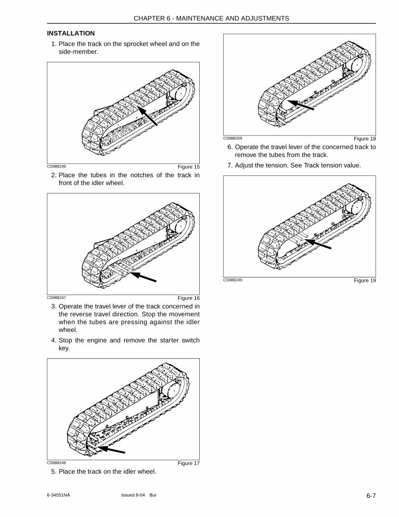
CHAPTER 6 - MAINTENANCE AND ADJUSTMENTS
INSTALLATION
1. Place the track on the sprocket wheel and on the side-member.
CS98B246 Figure 15
2. Place the tubes in the notches of the track in front of the idler wheel.
CS98B247 Figure 16
3. Operate the travel lever of the track concerned in the reverse travel direction. Stop the movement when the tubes are pressing against the idler wheel.
4. Stop the engine and remove the starter switch key.
CS98B248 Figure 17
5. Place the track on the idler wheel.
CS98B209 Figure 18
6. Operate the travel lever of the concerned track to remove the tubes from the track.
7. Adjust the tension. See Track tension value.
CS98B249 Figure 19
6-76-34551NA Issued 8-04 Bur
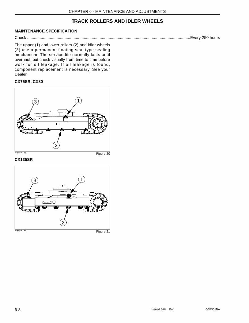
CHAPTER 6 - MAINTENANCE AND ADJUSTMENTS
TRACK ROLLERS AND IDLER WHEELS
MAINTENANCE SPECIFICATION
Check ................................................................................................................................................Every 250 hours
The upper (1) and lower rollers (2) and idler wheels (3) use a permanent floating seal type sealing mechanism. The service life normally lasts until overhaul, but check visually from time to time before work for o i l leakage. I f oi l leakage is found, component replacement is necessary. See your Dealer.
CX75SR, CX80
CT02D180 Figure 20
CX135SR
CT02D181 Figure 21
13
2
13
2
6-8 Issued 8-04 Bur 6-34551NA
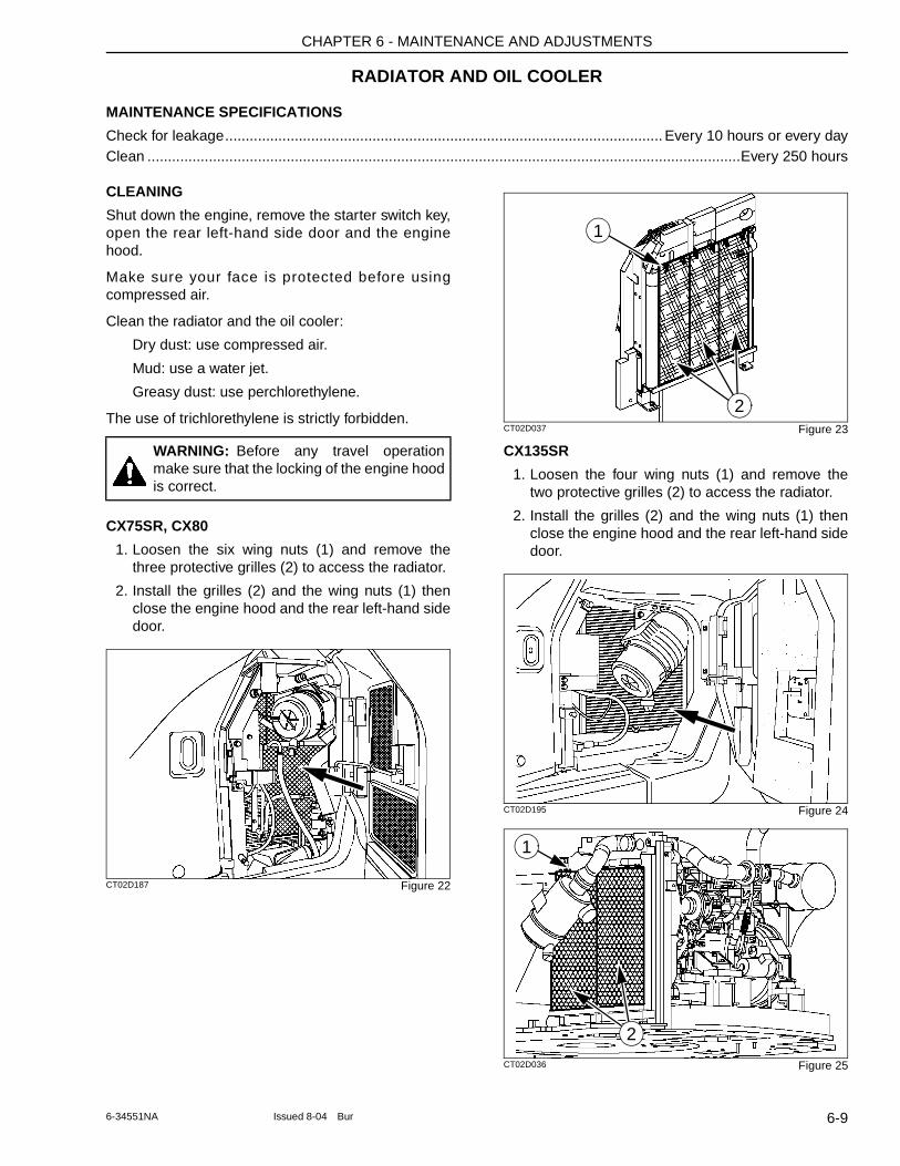
CHAPTER 6 - MAINTENANCE AND ADJUSTMENTS
RADIATOR AND OIL COOLER
MAINTENANCE SPECIFICATIONS
Check for leakage........................................................................................................... Every 10 hours or every dayClean .................................................................................................................................................Every 250 hours
CLEANING
Shut down the engine, remove the starter switch key, open the rear left-hand side door and the engine hood.
Make sure your face is protected before using compressed air.
Clean the radiator and the oil cooler:
Dry dust: use compressed air.
Mud: use a water jet.
Greasy dust: use perchlorethylene.
The use of trichlorethylene is strictly forbidden.
CX75SR, CX80
1. Loosen the six wing nuts (1) and remove the three protective grilles (2) to access the radiator.
2. Install the grilles (2) and the wing nuts (1) then close the engine hood and the rear left-hand side door.
CT02D187 Figure 22
CT02D037 Figure 23
CX135SR
1. Loosen the four wing nuts (1) and remove the two protective grilles (2) to access the radiator.
2. Install the grilles (2) and the wing nuts (1) then close the engine hood and the rear left-hand side door.
CT02D195 Figure 24
CT02D036 Figure 25
WARNING: Before any travel operation make sure that the locking of the engine hood is correct.
1
2
1
2
6-96-34551NA Issued 8-04 Bur
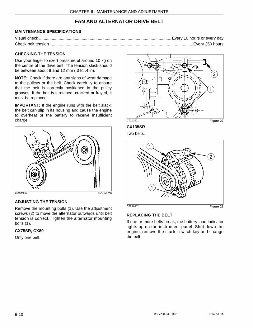
CHAPTER 6 - MAINTENANCE AND ADJUSTMENTS
FAN AND ALTERNATOR DRIVE BELT
MAINTENANCE SPECIFICATIONS
Visual check ................................................................................................................... Every 10 hours or every dayCheck belt tension .............................................................................................................................Every 250 hours
CHECKING THE TENSION
Use your finger to exert pressure of around 10 kg on the centre of the drive belt. The tension slack should be between about 8 and 12 mm (.3 to .4 in).
NOTE: Check if there are any signs of wear damage to the pulleys or the belt. Check carefully to ensure that the belt is correctly positioned in the pulley grooves. If the belt is stretched, cracked or frayed, it must be replaced.
IMPORTANT: If the engine runs with the belt slack, the belt can slip in its housing and cause the engine to overheat or the battery to receive insufficient charge.
CS98M560 Figure 26
ADJUSTING THE TENSION
Remove the mounting bolts (1). Use the adjustment screws (2) to move the alternator outwards until belt tension is correct. Tighten the alternator mounting bolts (1).
CX75SR, CX80
Only one belt.
CT02D201 Figure 27
CX135SR
Two belts.
CS99A852 Figure 28
REPLACING THE BELT
If one or more belts break, the battery load indicator lights up on the instrument panel. Shut down the engine, remove the starter switch key and change the belt.
2
1
2
1
1
6-10 Issued 8-04 Bur 6-34551NA
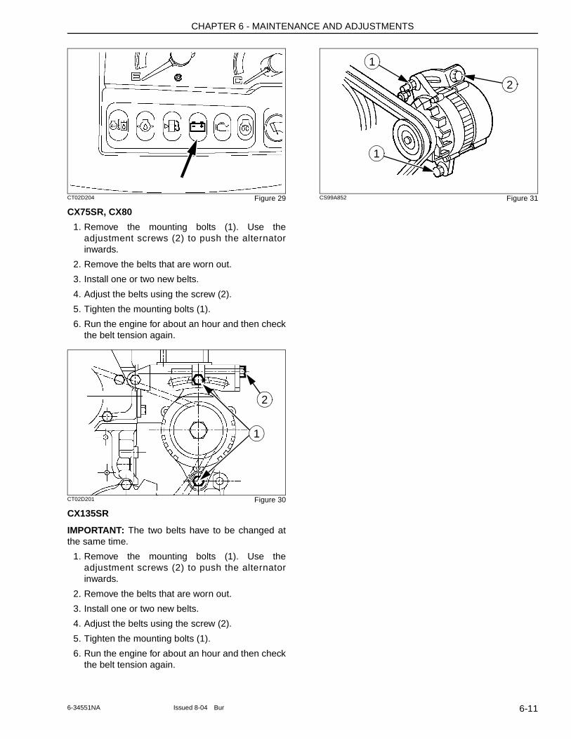
CHAPTER 6 - MAINTENANCE AND ADJUSTMENTS
CT02D204 Figure 29
CX75SR, CX80
1. Remove the mounting bolts (1). Use the adjustment screws (2) to push the alternator inwards.
2. Remove the belts that are worn out.
3. Install one or two new belts.
4. Adjust the belts using the screw (2).
5. Tighten the mounting bolts (1).
6. Run the engine for about an hour and then check the belt tension again.
CT02D201 Figure 30
CX135SR
IMPORTANT: The two belts have to be changed at the same time.
1. Remove the mounting bolts (1). Use the adjustment screws (2) to push the alternator inwards.
2. Remove the belts that are worn out.
3. Install one or two new belts.
4. Adjust the belts using the screw (2).
5. Tighten the mounting bolts (1).
6. Run the engine for about an hour and then check the belt tension again.
CS99A852 Figure 31
2
1
2
1
1
6-116-34551NA Issued 8-04 Bur
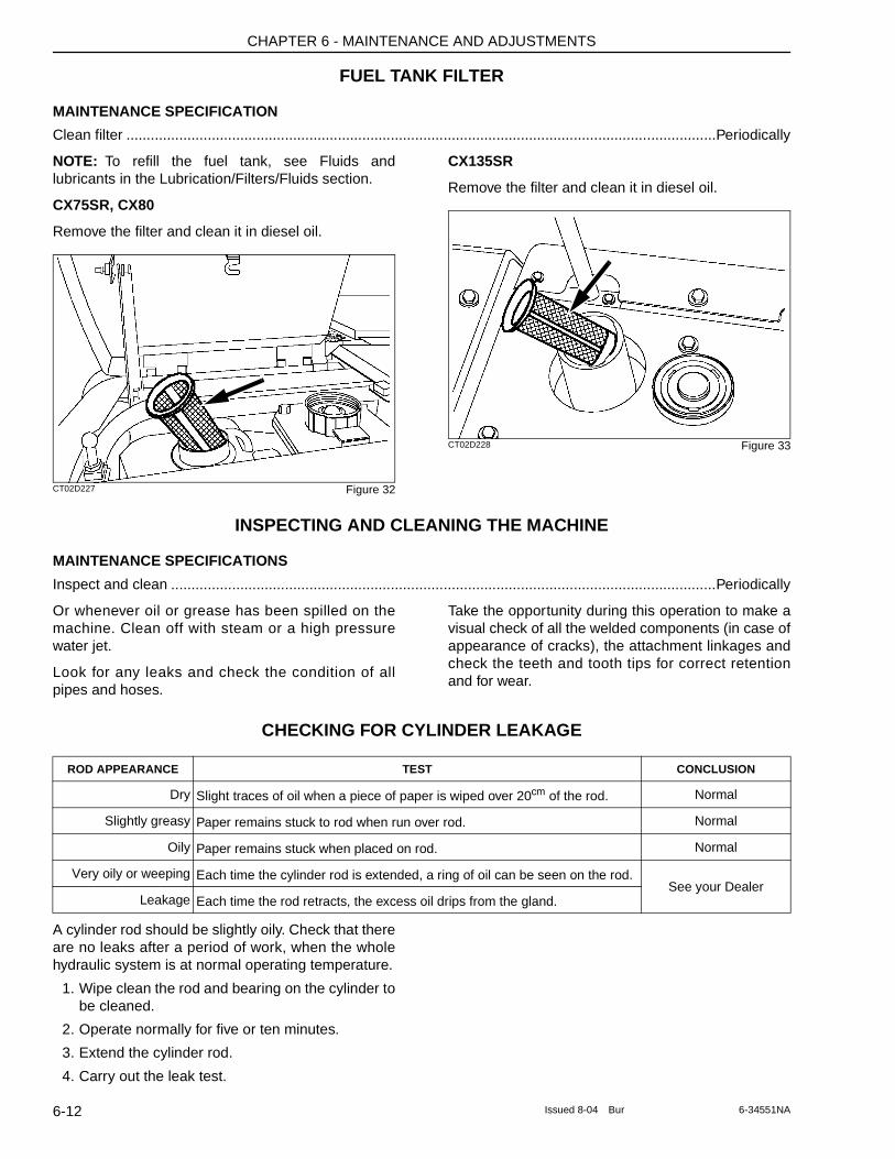
CHAPTER 6 - MAINTENANCE AND ADJUSTMENTS
FUEL TANK FILTER
MAINTENANCE SPECIFICATION
Clean filter .................................................................................................................................................Periodically
NOTE: To refill the fuel tank, see Fluids and lubricants in the Lubrication/Filters/Fluids section.
CX75SR, CX80
Remove the filter and clean it in diesel oil.
CT02D227 Figure 32
CX135SR
Remove the filter and clean it in diesel oil.
CT02D228 Figure 33
INSPECTING AND CLEANING THE MACHINE
MAINTENANCE SPECIFICATIONS
Inspect and clean ......................................................................................................................................Periodically
Or whenever oil or grease has been spilled on the machine. Clean off with steam or a high pressure water jet.
Look for any leaks and check the condition of all pipes and hoses.
Take the opportunity during this operation to make a visual check of all the welded components (in case of appearance of cracks), the attachment linkages and check the teeth and tooth tips for correct retention and for wear.
CHECKING FOR CYLINDER LEAKAGE
A cylinder rod should be slightly oily. Check that there are no leaks after a period of work, when the whole hydraulic system is at normal operating temperature.
1. Wipe clean the rod and bearing on the cylinder to be cleaned.
2. Operate normally for five or ten minutes.
3. Extend the cylinder rod.
4. Carry out the leak test.
ROD APPEARANCE TEST CONCLUSION
Dry Slight traces of oil when a piece of paper is wiped over 20cm of the rod. Normal
Slightly greasy Paper remains stuck to rod when run over rod. Normal
Oily Paper remains stuck when placed on rod. Normal
Very oily or weeping Each time the cylinder rod is extended, a ring of oil can be seen on the rod.See your Dealer
Leakage Each time the rod retracts, the excess oil drips from the gland.
6-12 Issued 8-04 Bur 6-34551NA
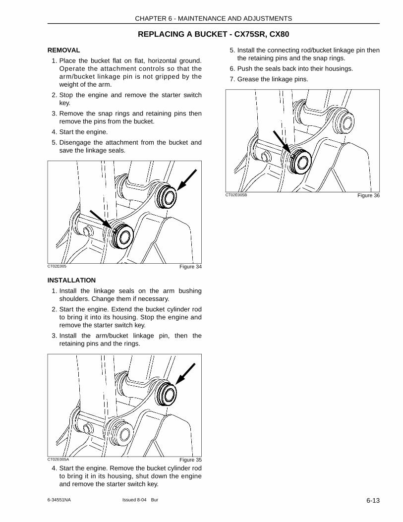
CHAPTER 6 - MAINTENANCE AND ADJUSTMENTS
REPLACING A BUCKET - CX75SR, CX80
REMOVAL
1. Place the bucket flat on flat, horizontal ground. Operate the attachment controls so that the arm/bucket linkage pin is not gripped by the weight of the arm.
2. Stop the engine and remove the starter switch key.
3. Remove the snap rings and retaining pins then remove the pins from the bucket.
4. Start the engine.
5. Disengage the attachment from the bucket and save the linkage seals.
CT02E005 Figure 34
INSTALLATION
1. Install the linkage seals on the arm bushing shoulders. Change them if necessary.
2. Start the engine. Extend the bucket cylinder rod to bring it into its housing. Stop the engine and remove the starter switch key.
3. Install the arm/bucket linkage pin, then the retaining pins and the rings.
CT02E005A Figure 35
4. Start the engine. Remove the bucket cylinder rod to bring it in its housing, shut down the engine and remove the starter switch key.
5. Install the connecting rod/bucket linkage pin then the retaining pins and the snap rings.
6. Push the seals back into their housings.
7. Grease the linkage pins.
CT02E005B Figure 36
6-136-34551NA Issued 8-04 Bur
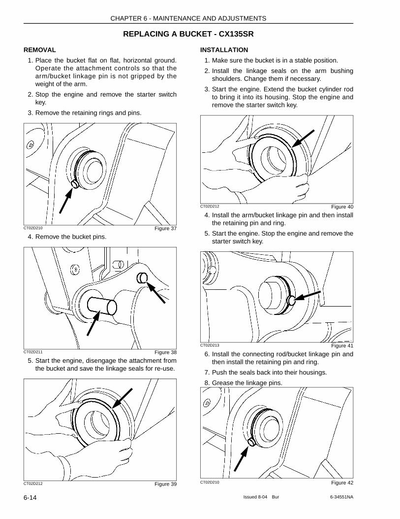
CHAPTER 6 - MAINTENANCE AND ADJUSTMENTS
REPLACING A BUCKET - CX135SR
REMOVAL
1. Place the bucket flat on flat, horizontal ground. Operate the attachment controls so that the arm/bucket linkage pin is not gripped by the weight of the arm.
2. Stop the engine and remove the starter switch key.
3. Remove the retaining rings and pins.
CT02D210 Figure 37
4. Remove the bucket pins.
CT02D211 Figure 38
5. Start the engine, disengage the attachment from the bucket and save the linkage seals for re-use.
CT02D212 Figure 39
INSTALLATION
1. Make sure the bucket is in a stable position.
2. Install the linkage seals on the arm bushing shoulders. Change them if necessary.
3. Start the engine. Extend the bucket cylinder rod to bring it into its housing. Stop the engine and remove the starter switch key.
CT02D212 Figure 40
4. Install the arm/bucket linkage pin and then install the retaining pin and ring.
5. Start the engine. Stop the engine and remove the starter switch key.
CT02D213 Figure 41
6. Install the connecting rod/bucket linkage pin and then install the retaining pin and ring.
7. Push the seals back into their housings.
8. Grease the linkage pins.
CT02D210 Figure 42
6-14 Issued 8-04 Bur 6-34551NA
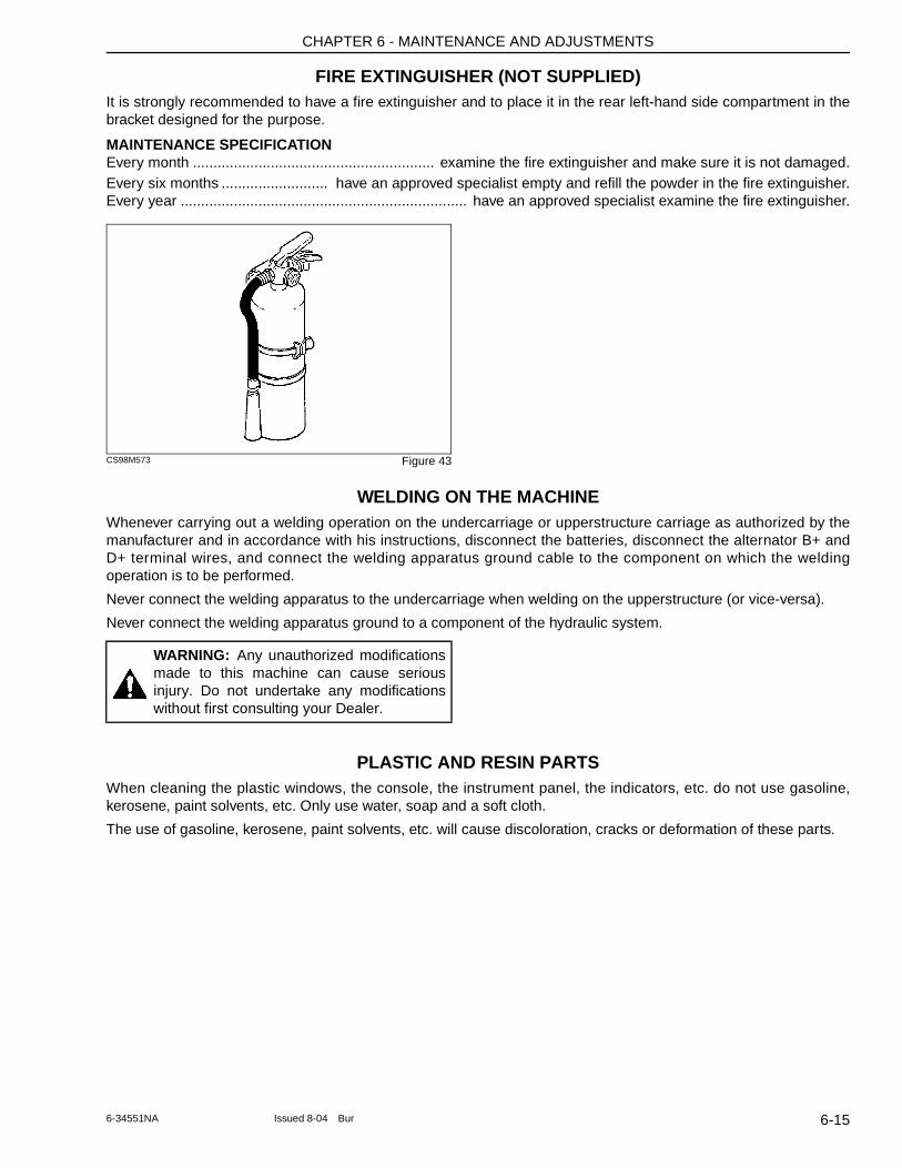
CHAPTER 6 - MAINTENANCE AND ADJUSTMENTS
FIRE EXTINGUISHER (NOT SUPPLIED)It is strongly recommended to have a fire extinguisher and to place it in the rear left-hand side compartment in the bracket designed for the purpose.
MAINTENANCE SPECIFICATIONEvery month ........................................................... examine the fire extinguisher and make sure it is not damaged.Every six months .......................... have an approved specialist empty and refill the powder in the fire extinguisher.Every year ...................................................................... have an approved specialist examine the fire extinguisher.
CS98M573 Figure 43
WELDING ON THE MACHINEWhenever carrying out a welding operation on the undercarriage or upperstructure carriage as authorized by the manufacturer and in accordance with his instructions, disconnect the batteries, disconnect the alternator B+ and D+ terminal wires, and connect the welding apparatus ground cable to the component on which the welding operation is to be performed.
Never connect the welding apparatus to the undercarriage when welding on the upperstructure (or vice-versa).
Never connect the welding apparatus ground to a component of the hydraulic system.
PLASTIC AND RESIN PARTSWhen cleaning the plastic windows, the console, the instrument panel, the indicators, etc. do not use gasoline, kerosene, paint solvents, etc. Only use water, soap and a soft cloth.
The use of gasoline, kerosene, paint solvents, etc. will cause discoloration, cracks or deformation of these parts.
WARNING: Any unauthorized modifications made to this machine can cause serious injury. Do not undertake any modifications without first consulting your Dealer.
6-156-34551NA Issued 8-04 Bur
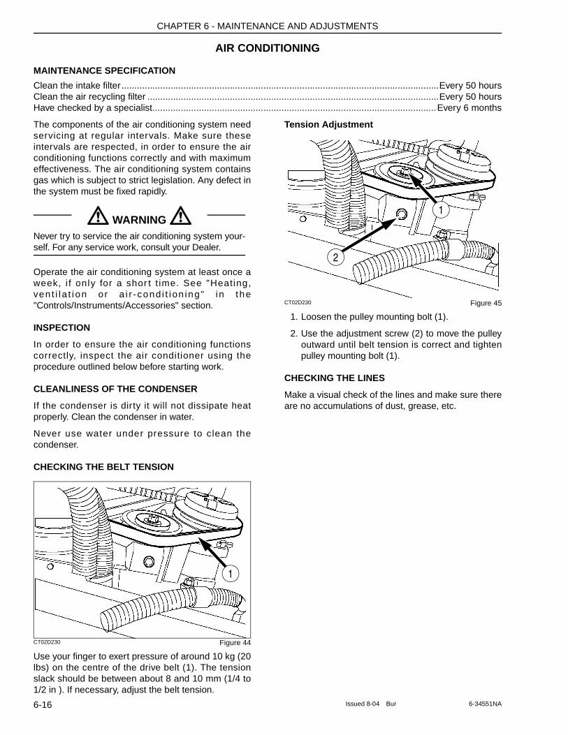
CHAPTER 6 - MAINTENANCE AND ADJUSTMENTS
AIR CONDITIONING
MAINTENANCE SPECIFICATION
Clean the intake filter...........................................................................................................................Every 50 hoursClean the air recycling filter .................................................................................................................Every 50 hoursHave checked by a specialist..............................................................................................................Every 6 months
The components of the air conditioning system need servicing at regular intervals. Make sure these intervals are respected, in order to ensure the air conditioning functions correctly and with maximum effectiveness. The air conditioning system contains gas which is subject to strict legislation. Any defect in the system must be fixed rapidly.
Operate the air conditioning system at least once a week, i f only for a shor t t ime. See "Heating, ven t i l a t i on or a i r -cond i t i on ing " i n the "Controls/Instruments/Accessories" section.
INSPECTION
In order to ensure the air conditioning functions correctly, inspect the air conditioner using the procedure outlined below before starting work.
CLEANLINESS OF THE CONDENSER
If the condenser is dirty it will not dissipate heat properly. Clean the condenser in water.
Never use water under pressure to clean the condenser.
CHECKING THE BELT TENSION
CT02D230 Figure 44
Use your finger to exert pressure of around 10 kg (20 lbs) on the centre of the drive belt (1). The tension slack should be between about 8 and 10 mm (1/4 to 1/2 in ). If necessary, adjust the belt tension.
Tension Adjustment
CT02D230 Figure 45
1. Loosen the pulley mounting bolt (1).
2. Use the adjustment screw (2) to move the pulley outward until belt tension is correct and tighten pulley mounting bolt (1).
CHECKING THE LINES
Make a visual check of the lines and make sure there are no accumulations of dust, grease, etc.
WARNING Never try to service the air conditioning system your-self. For any service work, consult your Dealer.
! !
1
1
2
6-16 Issued 8-04 Bur 6-34551NA
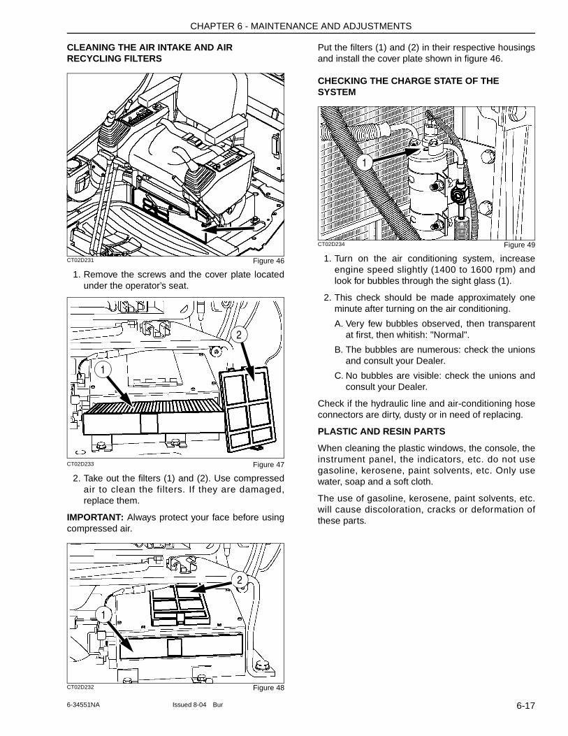
CHAPTER 6 - MAINTENANCE AND ADJUSTMENTS
CLEANING THE AIR INTAKE AND AIR RECYCLING FILTERS
CT02D231 Figure 46
1. Remove the screws and the cover plate located under the operator’s seat.
CT02D233 Figure 47
2. Take out the filters (1) and (2). Use compressed air to clean the filters. If they are damaged, replace them.
IMPORTANT: Always protect your face before using compressed air.
CT02D232 Figure 48
Put the filters (1) and (2) in their respective housings and install the cover plate shown in figure 46.
CHECKING THE CHARGE STATE OF THE SYSTEM
CT02D234 Figure 49
1. Turn on the air conditioning system, increase engine speed slightly (1400 to 1600 rpm) and look for bubbles through the sight glass (1).
2. This check should be made approximately one minute after turning on the air conditioning.
A. Very few bubbles observed, then transparent at first, then whitish: "Normal".
B. The bubbles are numerous: check the unions and consult your Dealer.
C. No bubbles are visible: check the unions and consult your Dealer.
Check if the hydraulic line and air-conditioning hose connectors are dirty, dusty or in need of replacing.
PLASTIC AND RESIN PARTS
When cleaning the plastic windows, the console, the instrument panel, the indicators, etc. do not use gasoline, kerosene, paint solvents, etc. Only use water, soap and a soft cloth.
The use of gasoline, kerosene, paint solvents, etc. will cause discoloration, cracks or deformation of these parts.
1
2
1
2
1
6-176-34551NA Issued 8-04 Bur
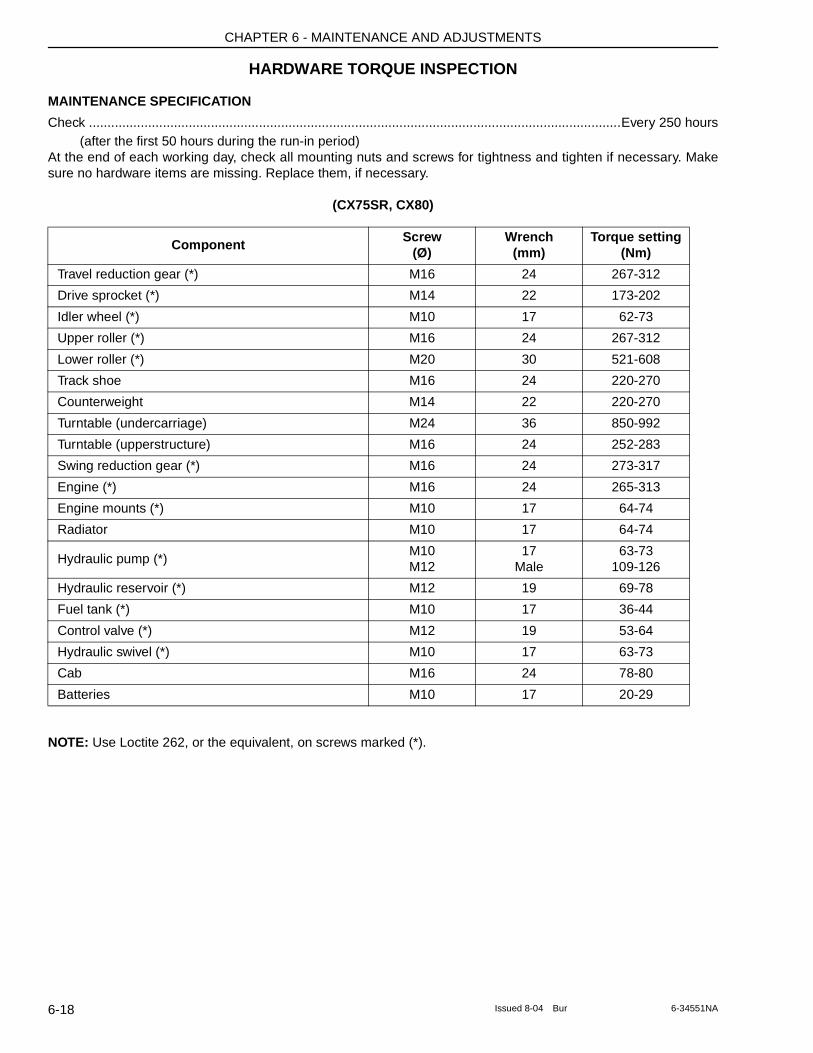
CHAPTER 6 - MAINTENANCE AND ADJUSTMENTS
HARDWARE TORQUE INSPECTION
MAINTENANCE SPECIFICATION
Check ................................................................................................................................................Every 250 hours(after the first 50 hours during the run-in period)
At the end of each working day, check all mounting nuts and screws for tightness and tighten if necessary. Make sure no hardware items are missing. Replace them, if necessary.
(CX75SR, CX80)
NOTE: Use Loctite 262, or the equivalent, on screws marked (*).
ComponentScrew
(Ø)Wrench
(mm)Torque setting
(Nm)
Travel reduction gear (*) M16 24 267-312
Drive sprocket (*) M14 22 173-202
Idler wheel (*) M10 17 62-73
Upper roller (*) M16 24 267-312
Lower roller (*) M20 30 521-608
Track shoe M16 24 220-270
Counterweight M14 22 220-270
Turntable (undercarriage) M24 36 850-992
Turntable (upperstructure) M16 24 252-283
Swing reduction gear (*) M16 24 273-317
Engine (*) M16 24 265-313
Engine mounts (*) M10 17 64-74
Radiator M10 17 64-74
Hydraulic pump (*)M10M12
17Male
63-73109-126
Hydraulic reservoir (*) M12 19 69-78
Fuel tank (*) M10 17 36-44
Control valve (*) M12 19 53-64
Hydraulic swivel (*) M10 17 63-73
Cab M16 24 78-80
Batteries M10 17 20-29
6-18 Issued 8-04 Bur 6-34551NA
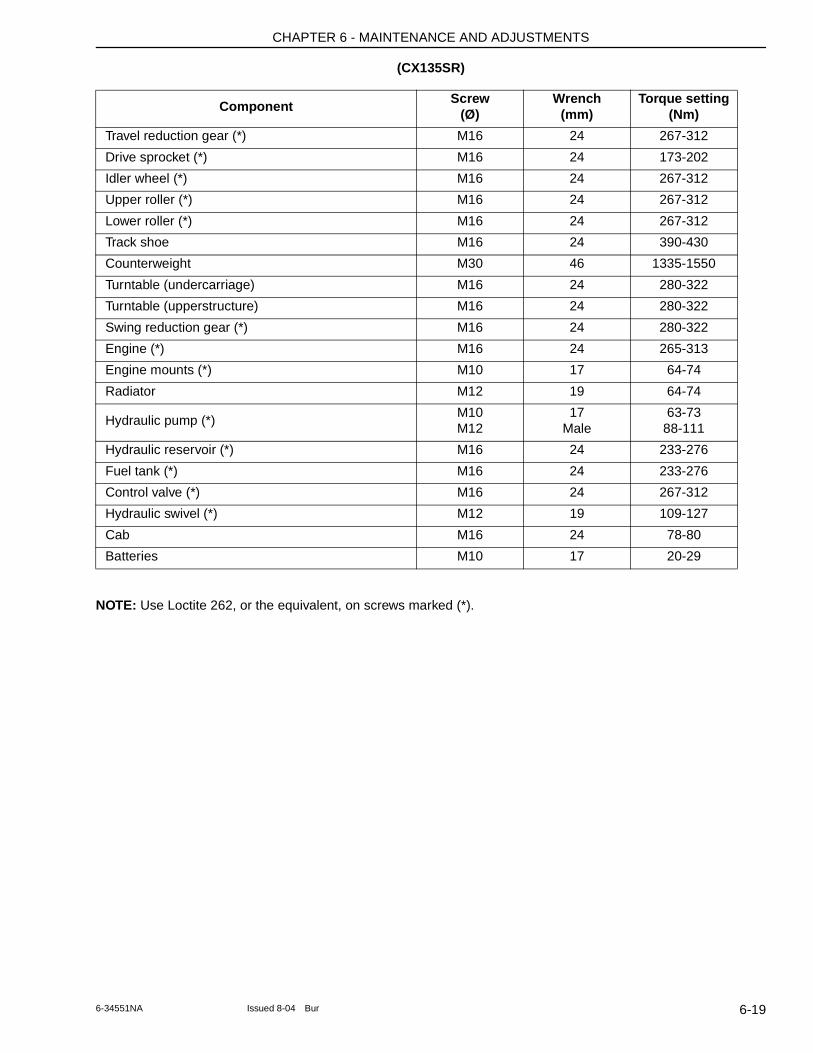
CHAPTER 6 - MAINTENANCE AND ADJUSTMENTS
(CX135SR)
NOTE: Use Loctite 262, or the equivalent, on screws marked (*).
ComponentScrew
(Ø)Wrench
(mm)Torque setting
(Nm)
Travel reduction gear (*) M16 24 267-312
Drive sprocket (*) M16 24 173-202
Idler wheel (*) M16 24 267-312
Upper roller (*) M16 24 267-312
Lower roller (*) M16 24 267-312
Track shoe M16 24 390-430
Counterweight M30 46 1335-1550
Turntable (undercarriage) M16 24 280-322
Turntable (upperstructure) M16 24 280-322
Swing reduction gear (*) M16 24 280-322
Engine (*) M16 24 265-313
Engine mounts (*) M10 17 64-74
Radiator M12 19 64-74
Hydraulic pump (*)M10M12
17Male
63-7388-111
Hydraulic reservoir (*) M16 24 233-276
Fuel tank (*) M16 24 233-276
Control valve (*) M16 24 267-312
Hydraulic swivel (*) M12 19 109-127
Cab M16 24 78-80
Batteries M10 17 20-29
6-196-34551NA Issued 8-04 Bur

CHAPTER 6 - MAINTENANCE AND ADJUSTMENTS
NOTES
6-20 Issued 8-04 Bur 6-34551NA
CHAPTER 7 - ELECTRICAL
Chapter 7
ELECTRICAL
TABLE OF CONTENTS
FUSES . . . . . . . . . . . . . . . . . . . . . . . . . . . . . . . . . . . . . . . . . . . . . . . . . . . . . . . . . . . . . . . . . . . . . . . . . . . . . . . . . 7-3Function Of The Fuses - CX75SR, CX80 . . . . . . . . . . . . . . . . . . . . . . . . . . . . . . . . . . . . . . . . . . . . . . . . . . . . 7-4Function Of The Fuses - CX135SR . . . . . . . . . . . . . . . . . . . . . . . . . . . . . . . . . . . . . . . . . . . . . . . . . . . . . . . . . 7-4
BATTERY . . . . . . . . . . . . . . . . . . . . . . . . . . . . . . . . . . . . . . . . . . . . . . . . . . . . . . . . . . . . . . . . . . . . . . . . . . . . . . . 7-5Maintenance Specification . . . . . . . . . . . . . . . . . . . . . . . . . . . . . . . . . . . . . . . . . . . . . . . . . . . . . . . . . . . . . . . . 7-5Access to The Batteries . . . . . . . . . . . . . . . . . . . . . . . . . . . . . . . . . . . . . . . . . . . . . . . . . . . . . . . . . . . . . . . . . . 7-5Checking A Battery . . . . . . . . . . . . . . . . . . . . . . . . . . . . . . . . . . . . . . . . . . . . . . . . . . . . . . . . . . . . . . . . . . . . . 7-6Replacing A Battery - CX75SR, CX80 . . . . . . . . . . . . . . . . . . . . . . . . . . . . . . . . . . . . . . . . . . . . . . . . . . . . . . . 7-6Replacing the Batteries - CX135SR . . . . . . . . . . . . . . . . . . . . . . . . . . . . . . . . . . . . . . . . . . . . . . . . . . . . . . . . . 7-7
CONNECTING ONE OR TWO BOOSTER BATTERIES . . . . . . . . . . . . . . . . . . . . . . . . . . . . . . . . . . . . . . . . . . . 7-8
ALTERNATOR . . . . . . . . . . . . . . . . . . . . . . . . . . . . . . . . . . . . . . . . . . . . . . . . . . . . . . . . . . . . . . . . . . . . . . . . . . . 7-8Maintenance Specification . . . . . . . . . . . . . . . . . . . . . . . . . . . . . . . . . . . . . . . . . . . . . . . . . . . . . . . . . . . . . . . . 7-8
STARTER MOTOR . . . . . . . . . . . . . . . . . . . . . . . . . . . . . . . . . . . . . . . . . . . . . . . . . . . . . . . . . . . . . . . . . . . . . . . 7-8Maintenance Specification . . . . . . . . . . . . . . . . . . . . . . . . . . . . . . . . . . . . . . . . . . . . . . . . . . . . . . . . . . . . . . . . 7-8
REPLACING A BULB . . . . . . . . . . . . . . . . . . . . . . . . . . . . . . . . . . . . . . . . . . . . . . . . . . . . . . . . . . . . . . . . . . . . . . 7-9Operator’s Compartment Lighting . . . . . . . . . . . . . . . . . . . . . . . . . . . . . . . . . . . . . . . . . . . . . . . . . . . . . . . . . . 7-9Working Lights On The Cab and On The Attachment . . . . . . . . . . . . . . . . . . . . . . . . . . . . . . . . . . . . . . . . . . . 7-9
ADJUSTING THE WORKING LIGHTS . . . . . . . . . . . . . . . . . . . . . . . . . . . . . . . . . . . . . . . . . . . . . . . . . . . . . . . 7-10Cab . . . . . . . . . . . . . . . . . . . . . . . . . . . . . . . . . . . . . . . . . . . . . . . . . . . . . . . . . . . . . . . . . . . . . . . . . . . . . . . . . 7-10Attachment . . . . . . . . . . . . . . . . . . . . . . . . . . . . . . . . . . . . . . . . . . . . . . . . . . . . . . . . . . . . . . . . . . . . . . . . . . . 7-10
7-1Issued 8-04 Bur 6-34551NA

CHAPTER 7 - ELECTRICAL
NOTES
7-2 Issued 8-04 Bur 6-34551NA
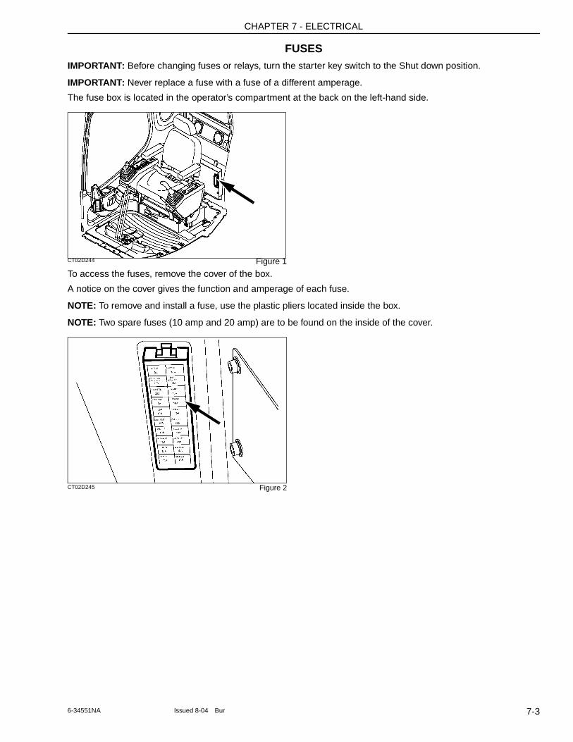
CHAPTER 7 - ELECTRICAL
FUSESIMPORTANT: Before changing fuses or relays, turn the starter key switch to the Shut down position.
IMPORTANT: Never replace a fuse with a fuse of a different amperage.
The fuse box is located in the operator’s compartment at the back on the left-hand side.
CT02D244 Figure 1
To access the fuses, remove the cover of the box.
A notice on the cover gives the function and amperage of each fuse.
NOTE: To remove and install a fuse, use the plastic pliers located inside the box.
NOTE: Two spare fuses (10 amp and 20 amp) are to be found on the inside of the cover.
CT02D245 Figure 2
7-36-34551NA Issued 8-04 Bur
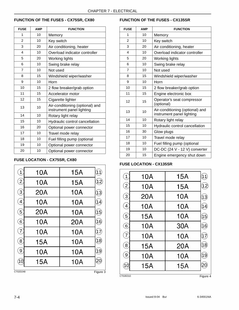
CHAPTER 7 - ELECTRICAL
FUNCTION OF THE FUSES - CX75SR, CX80
FUSE LOCATION - CX75SR, CX80
CT02D248 Figure 3
FUNCTION OF THE FUSES - CX135SR
FUSE LOCATION - CX135SR
CT02E010 Figure 4
FUSE AMP FUNCTION
1 10 Memory2 10 Key switch3 20 Air conditioning, heater4 10 Overload indicator controller5 20 Working lights6 10 Swing brake relay7 10 Not used8 15 Windshield wiper/washer9 10 Horn
10 15 2 flow breaker/grab option11 15 Accelerator motor12 15 Cigarette lighter
13 10 Air-conditioning (optional) and instrument panel lighting
14 10 Rotary light relay15 10 Hydraulic control cancellation16 20 Optional power connector17 10 Travel mode relay18 10 Fuel filling pump (optional19 10 Optional power connector20 10 Optional power connector
11
12
13
14
15
16
17
18
19
20
1
2
3
4
5
6
7
8
9
10
FUSE AMP FUNCTION
1 10 Memory2 10 Key switch3 20 Air conditioning, heater4 10 Overload indicator controller5 20 Working lights6 10 Swing brake relay7 10 Not used8 15 Windshield wiper/washer9 10 Horn
10 15 2 flow breaker/grab option11 15 Engine electronic box
12 15 Operator’s seat compressor (optional)
13 10 Air-conditioning (optional) and instrument panel lighting
14 10 Rotary light relay15 10 Hydraulic control cancellation16 30 Glow plugs17 10 Travel mode relay18 10 Fuel filling pump (optional19 10 DC-DC (24 V - 12 V) converter20 15 Engine emergency shut down
11
12
13
14
15
16
17
18
19
20
1
2
3
4
5
6
7
8
9
10
7-4 Issued 8-04 Bur 6-34551NA
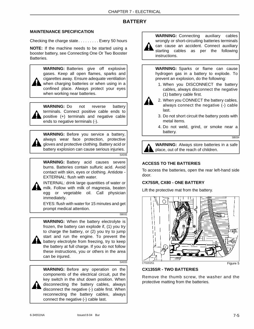
CHAPTER 7 - ELECTRICAL
BATTERY
MAINTENANCE SPECIFICATION
Checking the charge state. . . . . . . . . Every 50 hours
NOTE: If the machine needs to be started using a booster battery, see Connecting One Or Two Booster Batteries.
SA046
SB032
SA033
SB034
ACCESS TO THE BATTERIES
To access the batteries, open the rear left-hand side door.
CX75SR, CX80 - ONE BATTERY
Lift the protective mat from the battery.
CT02D251 Figure 5
CX135SR - TWO BATTERIES
Remove the thumb screw, the washer and the protective matting from the batteries.
WARNING: Batteries give off explosive gases. Keep all open flames, sparks and cigarettes away. Ensure adequate ventilation when charging batteries or when using in a confined place. Always protect your eyes when working near batteries.
WARNING: Do not reverse battery terminals. Connect positive cable ends to positive (+) terminals and negative cable ends to negative terminals (-).
WARNING: Before you service a battery, always wear face protection, protective gloves and protective clothing. Battery acid or battery explosion can cause serious injuries.
WARNING: Battery acid causes severe burns. Batteries contain sulfuric acid. Avoid contact with skin, eyes or clothing. Antidote - EXTERNAL: flush with water.INTERNAL: drink large quantities of water or milk. Follow with milk of magnesia, beaten egg or vegetable oil. Call physician immediately.EYES: flush with water for 15 minutes and get prompt medical attention.
WARNING: When the battery electrolyte is frozen, the battery can explode if, (1) you try to charge the battery, or (2) you try to jump start and run the engine. To prevent the battery electrolyte from freezing, try to keep the battery at full charge. If you do not follow these instructions, you or others in the area can be injured.
WARNING: Before any operation on the components of the electrical circuit, put the key switch in the shut down position. When disconnecting the battery cables, always disconnect the negative (-) cable first. When reconnecting the battery cables, always connect the negative (-) cable last.
WARNING: Connecting auxiliary cables wrongly or short-circuiting batteries terminals can cause an accident. Connect auxiliary starting cables as per the following instructions.
WARNING: Sparks or flame can cause hydrogen gas in a battery to explode. To prevent an explosion, do the following:
1. When you DISCONNECT the battery cables, always disconnect the negative (1) battery cable first.
2. When you CONNECT the battery cables, always connect the negative (-) cable last.
3. Do not short circuit the battery posts with metal items.
4. Do not weld, grind, or smoke near a battery.
WARNING: Always store batteries in a safe place, out of the reach of children.
7-56-34551NA Issued 8-04 Bur
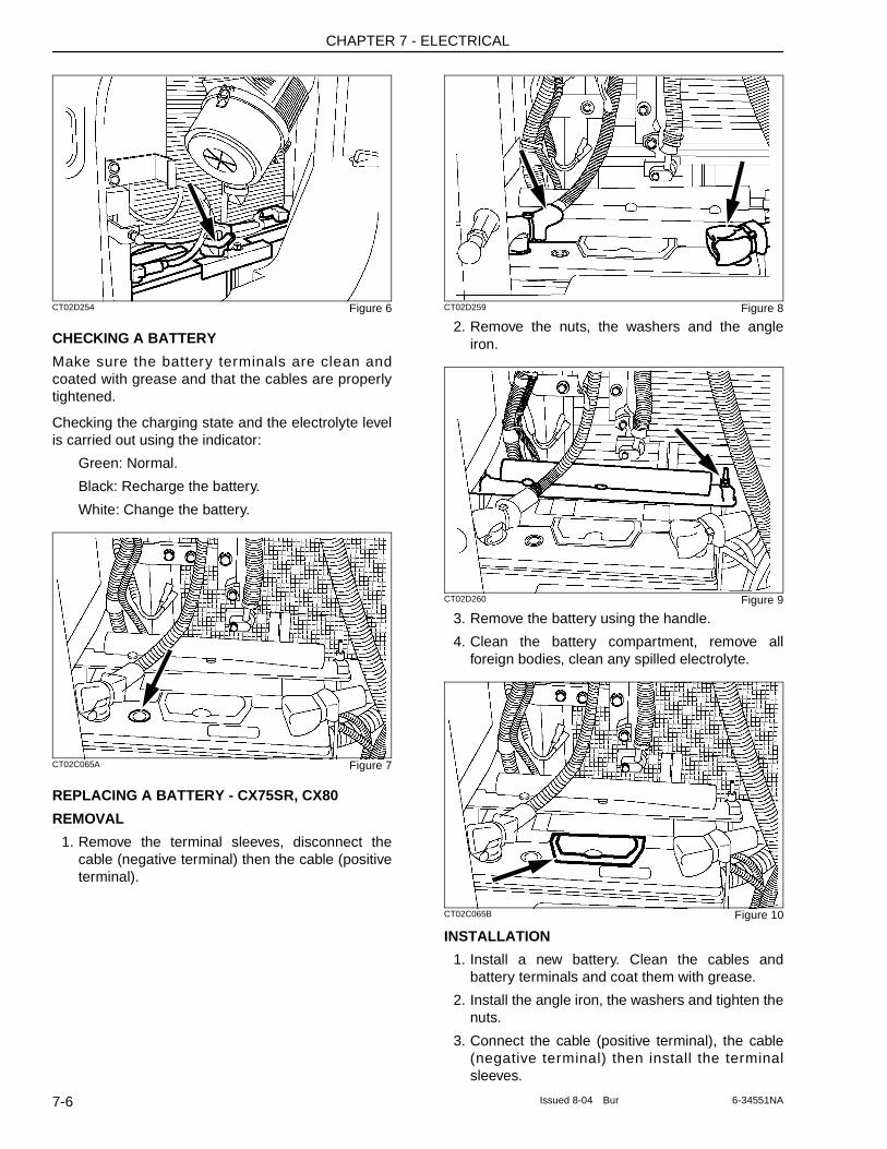
CHAPTER 7 - ELECTRICAL
CT02D254 Figure 6
CHECKING A BATTERY
Make sure the battery terminals are clean and coated with grease and that the cables are properly tightened.
Checking the charging state and the electrolyte level is carried out using the indicator:
Green: Normal.
Black: Recharge the battery.
White: Change the battery.
CT02C065A Figure 7
REPLACING A BATTERY - CX75SR, CX80
REMOVAL
1. Remove the terminal sleeves, disconnect the cable (negative terminal) then the cable (positive terminal).
CT02D259 Figure 8
2. Remove the nuts, the washers and the angle iron.
CT02D260 Figure 9
3. Remove the battery using the handle.
4. Clean the battery compartment, remove all foreign bodies, clean any spilled electrolyte.
CT02C065B Figure 10
INSTALLATION
1. Install a new battery. Clean the cables and battery terminals and coat them with grease.
2. Install the angle iron, the washers and tighten the nuts.
3. Connect the cable (positive terminal), the cable (negative terminal) then install the terminal sleeves.
7-6 Issued 8-04 Bur 6-34551NA
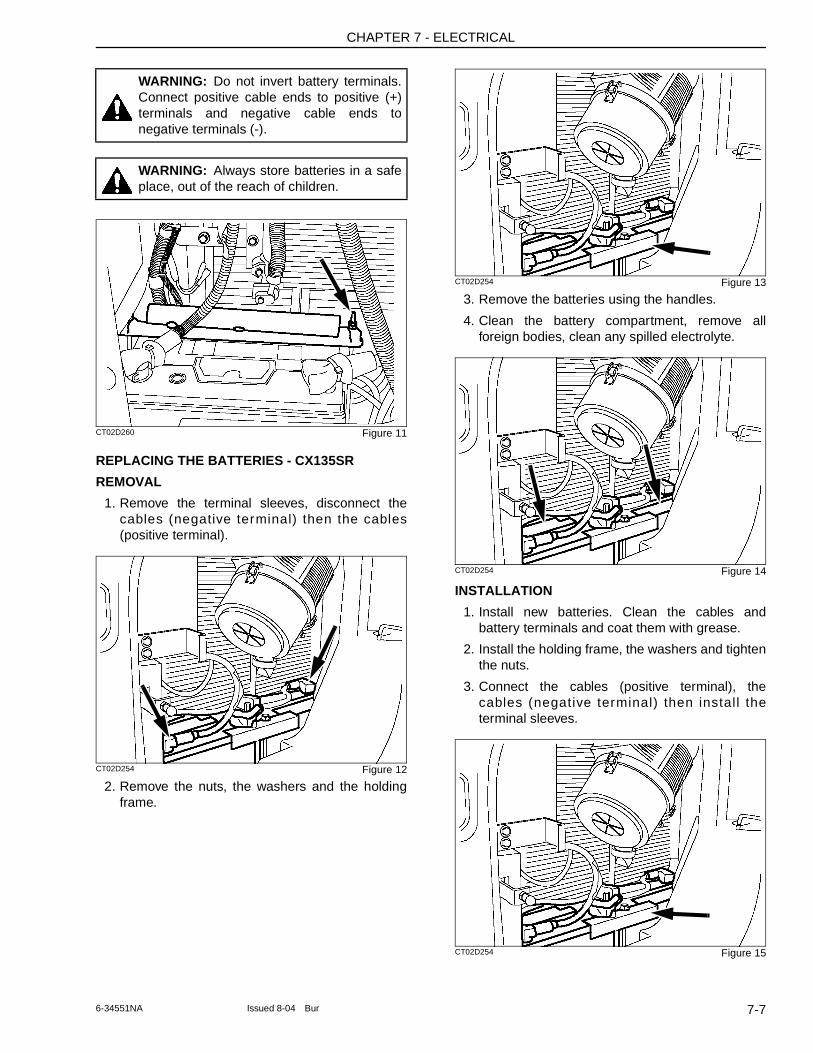
CHAPTER 7 - ELECTRICAL
CT02D260 Figure 11
REPLACING THE BATTERIES - CX135SR
REMOVAL
1. Remove the terminal sleeves, disconnect the cables (negative terminal) then the cables (positive terminal).
CT02D254 Figure 12
2. Remove the nuts, the washers and the holding frame.
CT02D254 Figure 13
3. Remove the batteries using the handles.
4. Clean the battery compartment, remove all foreign bodies, clean any spilled electrolyte.
CT02D254 Figure 14
INSTALLATION
1. Install new batteries. Clean the cables and battery terminals and coat them with grease.
2. Install the holding frame, the washers and tighten the nuts.
3. Connect the cables (positive terminal), the cables (negative terminal) then install the terminal sleeves.
CT02D254 Figure 15
WARNING: Do not invert battery terminals. Connect positive cable ends to positive (+) terminals and negative cable ends to negative terminals (-).
WARNING: Always store batteries in a safe place, out of the reach of children.
7-76-34551NA Issued 8-04 Bur
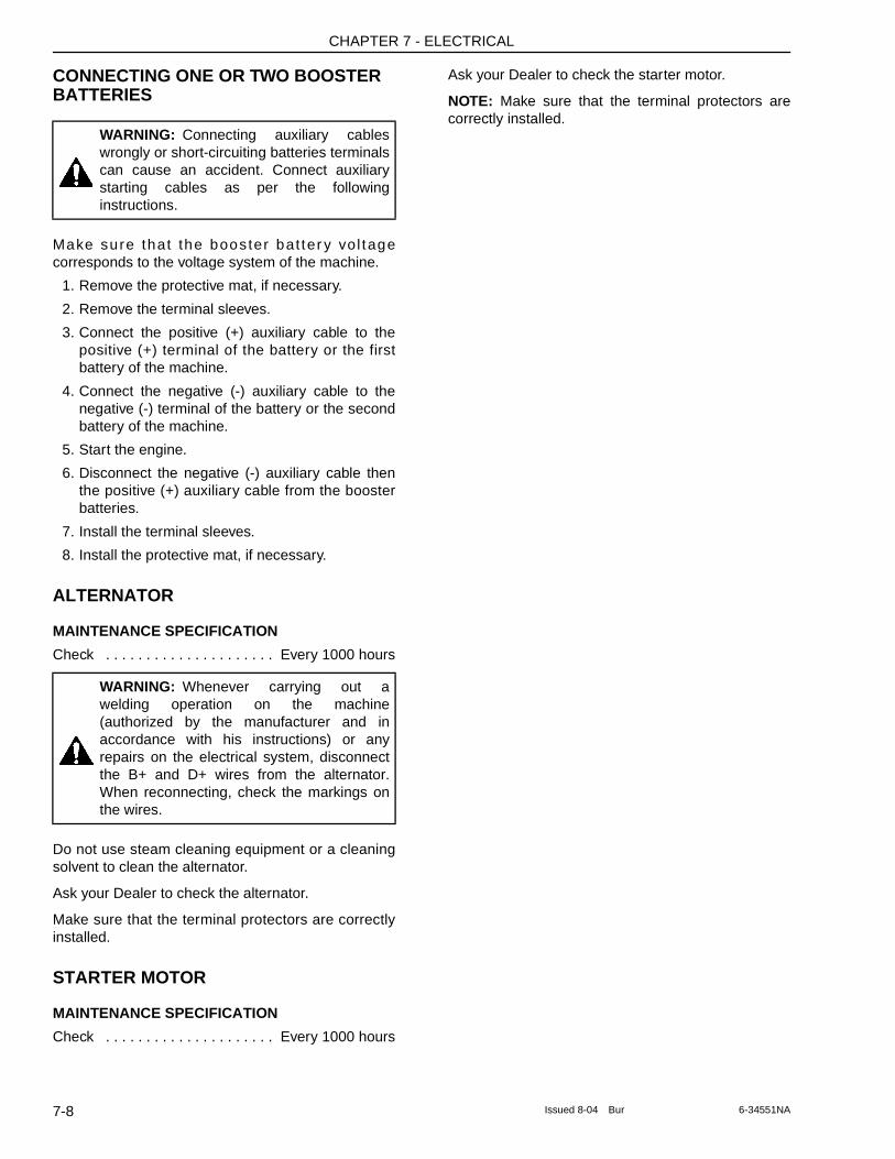
CHAPTER 7 - ELECTRICAL
CONNECTING ONE OR TWO BOOSTER BATTERIES
Make sure that the booster bat ter y vol tage corresponds to the voltage system of the machine.
1. Remove the protective mat, if necessary.
2. Remove the terminal sleeves.
3. Connect the positive (+) auxiliary cable to the positive (+) terminal of the battery or the first battery of the machine.
4. Connect the negative (-) auxiliary cable to the negative (-) terminal of the battery or the second battery of the machine.
5. Start the engine.
6. Disconnect the negative (-) auxiliary cable then the positive (+) auxiliary cable from the booster batteries.
7. Install the terminal sleeves.
8. Install the protective mat, if necessary.
ALTERNATOR
MAINTENANCE SPECIFICATION
Check . . . . . . . . . . . . . . . . . . . . . Every 1000 hours
Do not use steam cleaning equipment or a cleaning solvent to clean the alternator.
Ask your Dealer to check the alternator.
Make sure that the terminal protectors are correctly installed.
STARTER MOTOR
MAINTENANCE SPECIFICATION
Check . . . . . . . . . . . . . . . . . . . . . Every 1000 hours
Ask your Dealer to check the starter motor.
NOTE: Make sure that the terminal protectors are correctly installed.
WARNING: Connecting auxiliary cables wrongly or short-circuiting batteries terminals can cause an accident. Connect auxiliary starting cables as per the following instructions.
WARNING: Whenever carrying out a welding operation on the machine (authorized by the manufacturer and in accordance with his instructions) or any repairs on the electrical system, disconnect the B+ and D+ wires from the alternator. When reconnecting, check the markings on the wires.
7-8 Issued 8-04 Bur 6-34551NA
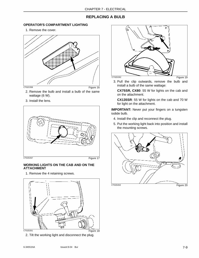
CHAPTER 7 - ELECTRICAL
REPLACING A BULB
OPERATOR’S COMPARTMENT LIGHTING
1. Remove the cover.
CT02C058 Figure 16
2. Remove the bulb and install a bulb of the same wattage (6 W).
3. Install the lens.
CT02D267 Figure 17
WORKING LIGHTS ON THE CAB AND ON THE ATTACHMENT
1. Remove the 4 retaining screws.
CT02D261 Figure 18
2. Tilt the working light and disconnect the plug.
‘CT02D262 Figure 19
3. Pull the clip outwards, remove the bulb and install a bulb of the same wattage:
CX75SR, CX80: 55 W for lights on the cab and on the attachment.
CX135SR: 55 W for lights on the cab and 70 W for light on the attachment.
IMPORTANT: Never put your fingers on a tungsten iodide bulb.
4. Install the clip and reconnect the plug.
5. Put the working light back into position and install the mounting screws.
CT02D263 Figure 20
7-96-34551NA Issued 8-04 Bur
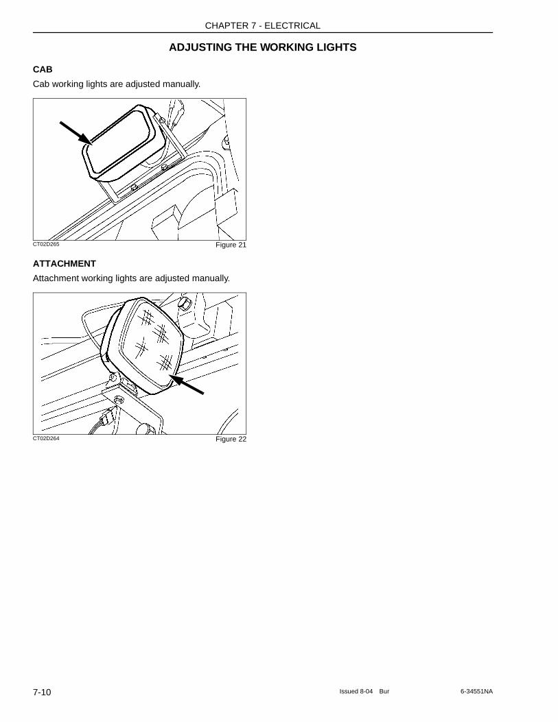
CHAPTER 7 - ELECTRICAL
ADJUSTING THE WORKING LIGHTS
CAB
Cab working lights are adjusted manually.
CT02D265 Figure 21
ATTACHMENT
Attachment working lights are adjusted manually.
CT02D264 Figure 22
7-10 Issued 8-04 Bur 6-34551NA
CHAPTER 8 - SPECIFICATIONS
Chapter 8
SPECIFICATIONS
TABLE OF CONTENTS
ENGINES . . . . . . . . . . . . . . . . . . . . . . . . . . . . . . . . . . . . . . . . . . . . . . . . . . . . . . . . . . . . . . . . . . . . . . . . . . . . . . . 8-3CX75SR, CX80 . . . . . . . . . . . . . . . . . . . . . . . . . . . . . . . . . . . . . . . . . . . . . . . . . . . . . . . . . . . . . . . . . . . . . . . . 8-3CX135SR . . . . . . . . . . . . . . . . . . . . . . . . . . . . . . . . . . . . . . . . . . . . . . . . . . . . . . . . . . . . . . . . . . . . . . . . . . . . . 8-3
ELECTRICAL SYSTEMS . . . . . . . . . . . . . . . . . . . . . . . . . . . . . . . . . . . . . . . . . . . . . . . . . . . . . . . . . . . . . . . . . . . 8-3CX75SR, CX80 . . . . . . . . . . . . . . . . . . . . . . . . . . . . . . . . . . . . . . . . . . . . . . . . . . . . . . . . . . . . . . . . . . . . . . . . 8-3CX135SR . . . . . . . . . . . . . . . . . . . . . . . . . . . . . . . . . . . . . . . . . . . . . . . . . . . . . . . . . . . . . . . . . . . . . . . . . . . . . 8-3
HYDRAULIC SYSTEM - CX75SR, CX80 . . . . . . . . . . . . . . . . . . . . . . . . . . . . . . . . . . . . . . . . . . . . . . . . . . . . . . . 8-4Control Valves . . . . . . . . . . . . . . . . . . . . . . . . . . . . . . . . . . . . . . . . . . . . . . . . . . . . . . . . . . . . . . . . . . . . . . . . . 8-4Swing . . . . . . . . . . . . . . . . . . . . . . . . . . . . . . . . . . . . . . . . . . . . . . . . . . . . . . . . . . . . . . . . . . . . . . . . . . . . . . . . 8-4Travel . . . . . . . . . . . . . . . . . . . . . . . . . . . . . . . . . . . . . . . . . . . . . . . . . . . . . . . . . . . . . . . . . . . . . . . . . . . . . . . . 8-4
HYDRAULIC SYSTEM - CX135SR . . . . . . . . . . . . . . . . . . . . . . . . . . . . . . . . . . . . . . . . . . . . . . . . . . . . . . . . . . . 8-4Control Valves . . . . . . . . . . . . . . . . . . . . . . . . . . . . . . . . . . . . . . . . . . . . . . . . . . . . . . . . . . . . . . . . . . . . . . . . . 8-4Swing . . . . . . . . . . . . . . . . . . . . . . . . . . . . . . . . . . . . . . . . . . . . . . . . . . . . . . . . . . . . . . . . . . . . . . . . . . . . . . . . 8-4Travel . . . . . . . . . . . . . . . . . . . . . . . . . . . . . . . . . . . . . . . . . . . . . . . . . . . . . . . . . . . . . . . . . . . . . . . . . . . . . . . . 8-4
UNDERCARRIAGE - CX75SR, CX80 . . . . . . . . . . . . . . . . . . . . . . . . . . . . . . . . . . . . . . . . . . . . . . . . . . . . . . . . . 8-5
UNDERCARRIAGE - CX135SR . . . . . . . . . . . . . . . . . . . . . . . . . . . . . . . . . . . . . . . . . . . . . . . . . . . . . . . . . . . . . . 8-5
CAPACITY OF SYSTEMS AND COMPONENTS . . . . . . . . . . . . . . . . . . . . . . . . . . . . . . . . . . . . . . . . . . . . . . . . 8-6CX75SR, CX80 . . . . . . . . . . . . . . . . . . . . . . . . . . . . . . . . . . . . . . . . . . . . . . . . . . . . . . . . . . . . . . . . . . . . . . . . 8-6CX135SR . . . . . . . . . . . . . . . . . . . . . . . . . . . . . . . . . . . . . . . . . . . . . . . . . . . . . . . . . . . . . . . . . . . . . . . . . . . . . 8-6
WEIGHTS . . . . . . . . . . . . . . . . . . . . . . . . . . . . . . . . . . . . . . . . . . . . . . . . . . . . . . . . . . . . . . . . . . . . . . . . . . . . . . . 8-6CX75SR, CX80 . . . . . . . . . . . . . . . . . . . . . . . . . . . . . . . . . . . . . . . . . . . . . . . . . . . . . . . . . . . . . . . . . . . . . . . . 8-6CX135SR . . . . . . . . . . . . . . . . . . . . . . . . . . . . . . . . . . . . . . . . . . . . . . . . . . . . . . . . . . . . . . . . . . . . . . . . . . . . . 8-6
GROUND PRESSURE . . . . . . . . . . . . . . . . . . . . . . . . . . . . . . . . . . . . . . . . . . . . . . . . . . . . . . . . . . . . . . . . . . . . . 8-6
BOOMS . . . . . . . . . . . . . . . . . . . . . . . . . . . . . . . . . . . . . . . . . . . . . . . . . . . . . . . . . . . . . . . . . . . . . . . . . . . . . . . . 8-6
ARMS . . . . . . . . . . . . . . . . . . . . . . . . . . . . . . . . . . . . . . . . . . . . . . . . . . . . . . . . . . . . . . . . . . . . . . . . . . . . . . . . . . 8-7
ESCO BUCKETS . . . . . . . . . . . . . . . . . . . . . . . . . . . . . . . . . . . . . . . . . . . . . . . . . . . . . . . . . . . . . . . . . . . . . . . . . 8-8CX75SR, CX80 . . . . . . . . . . . . . . . . . . . . . . . . . . . . . . . . . . . . . . . . . . . . . . . . . . . . . . . . . . . . . . . . . . . . . . . . 8-8CX135SR . . . . . . . . . . . . . . . . . . . . . . . . . . . . . . . . . . . . . . . . . . . . . . . . . . . . . . . . . . . . . . . . . . . . . . . . . . . . . 8-8
MACHINE OVERALL DIMENSIONS - CX75SR . . . . . . . . . . . . . . . . . . . . . . . . . . . . . . . . . . . . . . . . . . . . . . . . . 8-9
MACHINE OVERALL DIMENSIONS - CX80 . . . . . . . . . . . . . . . . . . . . . . . . . . . . . . . . . . . . . . . . . . . . . . . . . . . 8-10
MACHINE OVERALL DIMENSIONS - CX135SR . . . . . . . . . . . . . . . . . . . . . . . . . . . . . . . . . . . . . . . . . . . . . . . 8-11
WORKING RANGE - CX75SR . . . . . . . . . . . . . . . . . . . . . . . . . . . . . . . . . . . . . . . . . . . . . . . . . . . . . . . . . . . . . . 8-12
WORKING RANGE - CX80 . . . . . . . . . . . . . . . . . . . . . . . . . . . . . . . . . . . . . . . . . . . . . . . . . . . . . . . . . . . . . . . . . 8-15
WORKING RANGE - CX135SR . . . . . . . . . . . . . . . . . . . . . . . . . . . . . . . . . . . . . . . . . . . . . . . . . . . . . . . . . . . . . 8-16
LIFTING CAPACITIES . . . . . . . . . . . . . . . . . . . . . . . . . . . . . . . . . . . . . . . . . . . . . . . . . . . . . . . . . . . . . . . . . . . . 8-19cx75sr with 1.71 m (5 ft. 7 in) arm . . . . . . . . . . . . . . . . . . . . . . . . . . . . . . . . . . . . . . . . . . . . . . . . . . . . . . . . . 8-19cx75sr with 2.12 m (6 ft. 11 in) arm . . . . . . . . . . . . . . . . . . . . . . . . . . . . . . . . . . . . . . . . . . . . . . . . . . . . . . . . 8-19cx75sr with 1.75 m (5 ft. 9 in) arm with offset boom . . . . . . . . . . . . . . . . . . . . . . . . . . . . . . . . . . . . . . . . . . . . 8-19cx135sr with 2.39 m (7 ft. 10 in) arm . . . . . . . . . . . . . . . . . . . . . . . . . . . . . . . . . . . . . . . . . . . . . . . . . . . . . . . 8-20cx135sr with 2.85 m (9 ft. 4 in) arm . . . . . . . . . . . . . . . . . . . . . . . . . . . . . . . . . . . . . . . . . . . . . . . . . . . . . . . . 8-20
8-1Issued 8-04 Bur 6-34551NA

CHAPTER 8 - SPECIFICATIONS
8-2 Issued 8-04 Bur 6-34551NA
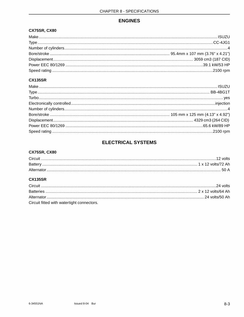
CHAPTER 8 - SPECIFICATIONS
ENGINES
CX75SR, CX80
Make................................................................................................................................................................. ISUZUType ..............................................................................................................................................................CC-4JG1Number of cylinders...................................................................................................................................................4Bore/stroke ............................................................................................................ 95.4mm x 107 mm (3.76” x 4.21”)Displacement.............................................................................................................................. 3059 cm3 (187 CID)Power EEC 80/1269 ............................................................................................................................39.1 kW/53 HPSpeed rating .................................................................................................................................................2100 rpm
CX135SR
Make................................................................................................................................................................. ISUZUType ........................................................................................................................................................... BB-4BG1TTurbo...................................................................................................................................................................... yesElectronically controlled..................................................................................................................................injectionNumber of cylinders...................................................................................................................................................4Bore/stroke ............................................................................................................ 105 mm x 125 mm (4.13” x 4.92”)Displacement.............................................................................................................................. 4329 cm3 (264 CID) Power EEC 80/1269 ............................................................................................................................65.6 kW/89 HPSpeed rating .................................................................................................................................................2100 rpm
ELECTRICAL SYSTEMS
CX75SR, CX80
Circuit ..............................................................................................................................................................12 voltsBattery ............................................................................................................................................ 1 x 12 volts/72 AhAlternator ............................................................................................................................................................. 50 A
CX135SR
Circuit ..............................................................................................................................................................24 voltsBatteries ......................................................................................................................................... 2 x 12 volts/64 AhAlternator .............................................................................................................................................. 24 volts/50 AhCircuit fitted with watertight connectors.
8-36-34551NA Issued 8-04 Bur
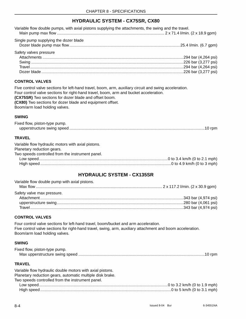
CHAPTER 8 - SPECIFICATIONS
HYDRAULIC SYSTEM - CX75SR, CX80Variable flow double pumps, with axial pistons supplying the attachments, the swing and the travel.
Main pump max flow ................................................................................................ 2 x 71.4 l/min. (2 x 18.9 gpm)
Single pump supplying the dozer bladeDozer blade pump max flow...................................................................................................25.4 l/min. (6.7 gpm)
Safety valves pressureAttachments ..............................................................................................................................294 bar (4,264 psi)Swing ........................................................................................................................................226 bar (3,277 psi)Travel .........................................................................................................................................294 bar (4,264 psi)Dozer blade ...............................................................................................................................226 bar (3,277 psi)
CONTROL VALVES
Five control valve sections for left-hand travel, boom, arm, auxiliary circuit and swing acceleration.Four control valve sections for right-hand travel, boom, arm and bucket acceleration.(CX75SR) Two sections for dozer blade and offset boom.(CX80) Two sections for dozer blade and equipment offset.Boom/arm load holding valves.
SWING
Fixed flow, piston-type pump.upperstructure swing speed .........................................................................................................................10 rpm
TRAVEL
Variable flow hydraulic motors with axial pistons.Planetary reduction gears.Two speeds controlled from the instrument panel.
Low speed...................................................................................................................0 to 3.4 km/h (0 to 2.1 mph)High speed .....................................................................................................................0 to 4.9 km/h (0 to 3 mph)
HYDRAULIC SYSTEM - CX135SRVariable flow double pump with axial pistons.
Max flow ................................................................................................................. 2 x 117.2 l/min. (2 x 30.9 gpm)
Safety valve max pressure.Attachment ................................................................................................................................343 bar (4,974 psi)upperstructure swing.................................................................................................................280 bar (4,061 psi)Travel .........................................................................................................................................343 bar (4,974 psi)
CONTROL VALVES
Four control valve sections for left-hand travel, boom/bucket and arm acceleration.Five control valve sections for right-hand travel, swing, arm, auxiliary attachment and boom acceleration.Boom/arm load holding valves.
SWING
Fixed flow, piston-type pump.Max upperstructure swing speed .................................................................................................................10 rpm
TRAVEL
Variable flow hydraulic double motors with axial pistons.Planetary reduction gears, automatic multiple disk brake.Two speeds controlled from the instrument panel.
Low speed...................................................................................................................0 to 3.2 km/h (0 to 1.9 mph)High speed .....................................................................................................................0 to 5 km/h (0 to 3.1 mph)
8-4 Issued 8-04 Bur 6-34551NA
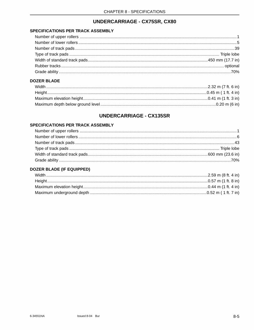
CHAPTER 8 - SPECIFICATIONS
UNDERCARRIAGE - CX75SR, CX80
SPECIFICATIONS PER TRACK ASSEMBLYNumber of upper rollers ........................................................................................................................................1Number of lower rollers .........................................................................................................................................5Number of track pads ..........................................................................................................................................39Type of track pads .................................................................................................................................. Triple lobeWidth of standard track pads........................................................................................................450 mm (17.7 in)Rubber tracks ............................................................................................................................................. optionalGrade ability .....................................................................................................................................................70%
DOZER BLADEWidth ............................................................................................................................................2.32 m (7 ft. 6 in)Height ..........................................................................................................................................0.45 m ( 1 ft. 4 in)Maximum elevation height............................................................................................................0.41 m (1 ft. 3 in)Maximum depth below ground level ....................................................................................................0.20 m (6 in)
UNDERCARRIAGE - CX135SR
SPECIFICATIONS PER TRACK ASSEMBLYNumber of upper rollers ........................................................................................................................................1Number of lower rollers .........................................................................................................................................6Number of track pads ..........................................................................................................................................43Type of track pads .................................................................................................................................. Triple lobeWidth of standard track pads........................................................................................................600 mm (23.6 in)Grade ability .....................................................................................................................................................70%
DOZER BLADE (IF EQUIPPED)Width ............................................................................................................................................2.59 m (8 ft. 4 in)Height ...........................................................................................................................................0.57 m (1 ft. 8 in)Maximum elevation height............................................................................................................0.44 m (1 ft. 4 in)Maximum underground depth .....................................................................................................0.52 m ( 1 ft. 7 in)
8-56-34551NA Issued 8-04 Bur
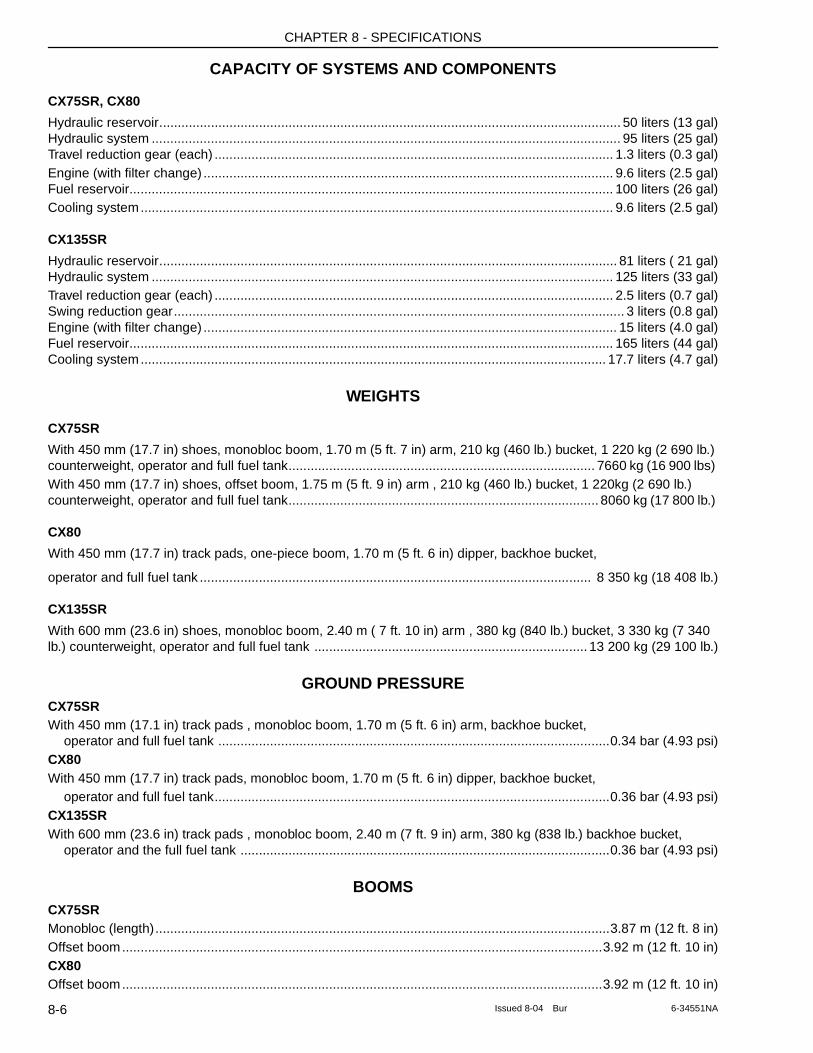
CHAPTER 8 - SPECIFICATIONS
CAPACITY OF SYSTEMS AND COMPONENTS
CX75SR, CX80
Hydraulic reservoir............................................................................................................................. 50 liters (13 gal)Hydraulic system ............................................................................................................................... 95 liters (25 gal)Travel reduction gear (each) ............................................................................................................ 1.3 liters (0.3 gal)Engine (with filter change) ............................................................................................................... 9.6 liters (2.5 gal)Fuel reservoir................................................................................................................................... 100 liters (26 gal)Cooling system................................................................................................................................ 9.6 liters (2.5 gal)
CX135SR
Hydraulic reservoir............................................................................................................................ 81 liters ( 21 gal)Hydraulic system ............................................................................................................................. 125 liters (33 gal)Travel reduction gear (each) ............................................................................................................ 2.5 liters (0.7 gal)Swing reduction gear.......................................................................................................................... 3 liters (0.8 gal)Engine (with filter change) ................................................................................................................ 15 liters (4.0 gal)Fuel reservoir................................................................................................................................... 165 liters (44 gal)Cooling system.............................................................................................................................. 17.7 liters (4.7 gal)
WEIGHTS
CX75SR
With 450 mm (17.7 in) shoes, monobloc boom, 1.70 m (5 ft. 7 in) arm, 210 kg (460 lb.) bucket, 1 220 kg (2 690 lb.) counterweight, operator and full fuel tank................................................................................... 7660 kg (16 900 lbs) With 450 mm (17.7 in) shoes, offset boom, 1.75 m (5 ft. 9 in) arm , 210 kg (460 lb.) bucket, 1 220kg (2 690 lb.) counterweight, operator and full fuel tank.................................................................................... 8060 kg (17 800 lb.)
CX80
With 450 mm (17.7 in) track pads, one-piece boom, 1.70 m (5 ft. 6 in) dipper, backhoe bucket,
operator and full fuel tank .......................................................................................................... 8 350 kg (18 408 lb.)
CX135SR
With 600 mm (23.6 in) shoes, monobloc boom, 2.40 m ( 7 ft. 10 in) arm , 380 kg (840 lb.) bucket, 3 330 kg (7 340 lb.) counterweight, operator and full fuel tank .......................................................................... 13 200 kg (29 100 lb.)
GROUND PRESSURECX75SR With 450 mm (17.1 in) track pads , monobloc boom, 1.70 m (5 ft. 6 in) arm, backhoe bucket,
operator and full fuel tank ..........................................................................................................0.34 bar (4.93 psi)CX80With 450 mm (17.7 in) track pads, monobloc boom, 1.70 m (5 ft. 6 in) dipper, backhoe bucket,
operator and full fuel tank...........................................................................................................0.36 bar (4.93 psi)CX135SRWith 600 mm (23.6 in) track pads , monobloc boom, 2.40 m (7 ft. 9 in) arm, 380 kg (838 lb.) backhoe bucket,
operator and the full fuel tank ....................................................................................................0.36 bar (4.93 psi)
BOOMS CX75SRMonobloc (length)...........................................................................................................................3.87 m (12 ft. 8 in)Offset boom..................................................................................................................................3.92 m (12 ft. 10 in)CX80Offset boom..................................................................................................................................3.92 m (12 ft. 10 in)
8-6 Issued 8-04 Bur 6-34551NA
CHAPTER 8 - SPECIFICATIONS
CX135SRMonobloc (length)...........................................................................................................................4.75 m (15 ft. 6 in)
ARMSCX75SRLength........................................................................................................ 1.70 m (5 ft. 7 in), and 2.12 m (6 ft. 11 in) Offset arm.........................................................................................................................................1.75 m (5 ft. 9 in)CX80Offset arm.................................................................................................... 1.70 m (5 ft. 7 in), and 2.10 m (6 ft. 9 in)CX135SRLength........................................................................................................ 2.40 m (7 ft. 10 in) and 2.85 m (9 ft. 4 in)
8-76-34551NA Issued 8-04 Bur
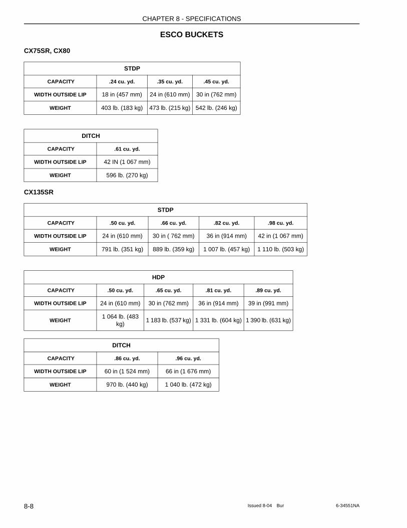
CHAPTER 8 - SPECIFICATIONS
ESCO BUCKETS
CX75SR, CX80
CX135SR
STDP
CAPACITY .24 cu. yd. .35 cu. yd. .45 cu. yd.
WIDTH OUTSIDE LIP 18 in (457 mm) 24 in (610 mm) 30 in (762 mm)
WEIGHT 403 lb. (183 kg) 473 lb. (215 kg) 542 lb. (246 kg)
DITCH
CAPACITY .61 cu. yd.
WIDTH OUTSIDE LIP 42 IN (1 067 mm)
WEIGHT 596 lb. (270 kg)
STDP
CAPACITY .50 cu. yd. .66 cu. yd. .82 cu. yd. .98 cu. yd.
WIDTH OUTSIDE LIP 24 in (610 mm) 30 in ( 762 mm) 36 in (914 mm) 42 in (1 067 mm)
WEIGHT 791 lb. (351 kg) 889 lb. (359 kg) 1 007 lb. (457 kg) 1 110 lb. (503 kg)
HDP
CAPACITY .50 cu. yd. .65 cu. yd. .81 cu. yd. .89 cu. yd.
WIDTH OUTSIDE LIP 24 in (610 mm) 30 in (762 mm) 36 in (914 mm) 39 in (991 mm)
WEIGHT 1 064 lb. (483
kg)1 183 lb. (537 kg) 1 331 lb. (604 kg) 1 390 lb. (631 kg)
DITCH
CAPACITY .86 cu. yd. .96 cu. yd.
WIDTH OUTSIDE LIP 60 in (1 524 mm) 66 in (1 676 mm)
WEIGHT 970 lb. (440 kg) 1 040 lb. (472 kg)
8-8 Issued 8-04 Bur 6-34551NA
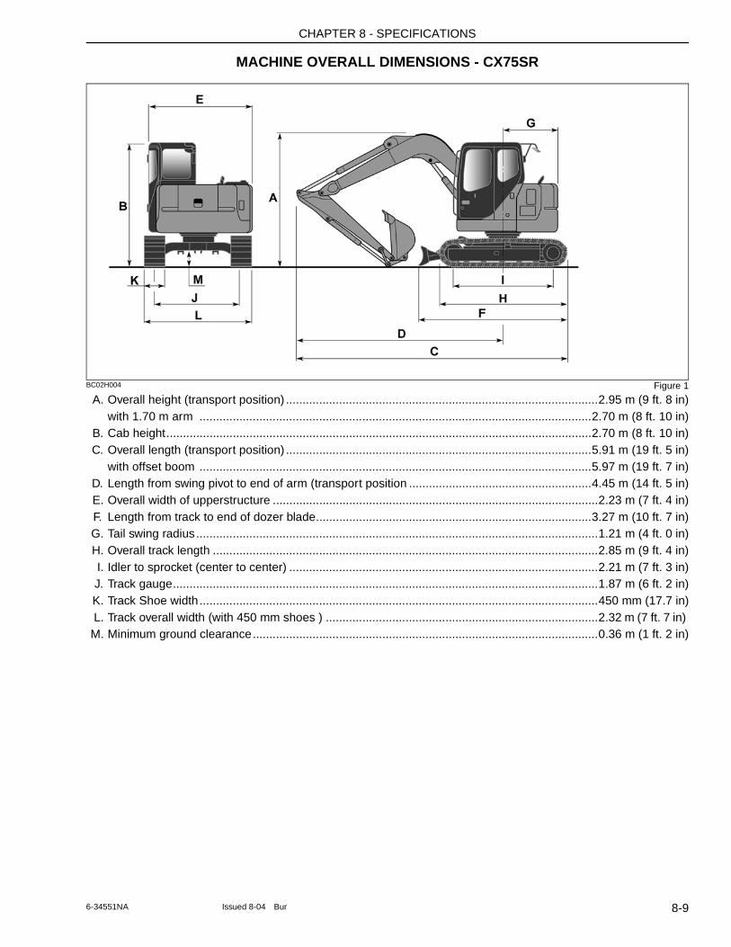
CHAPTER 8 - SPECIFICATIONS
MACHINE OVERALL DIMENSIONS - CX75SR
BC02H004 Figure 1
A. Overall height (transport position) ..............................................................................................2.95 m (9 ft. 8 in)with 1.70 m arm ......................................................................................................................2.70 m (8 ft. 10 in)
B. Cab height................................................................................................................................2.70 m (8 ft. 10 in)C. Overall length (transport position) ............................................................................................5.91 m (19 ft. 5 in)
with offset boom ......................................................................................................................5.97 m (19 ft. 7 in)D. Length from swing pivot to end of arm (transport position .......................................................4.45 m (14 ft. 5 in)E. Overall width of upperstructure ..................................................................................................2.23 m (7 ft. 4 in)F. Length from track to end of dozer blade...................................................................................3.27 m (10 ft. 7 in)G. Tail swing radius .........................................................................................................................1.21 m (4 ft. 0 in)H. Overall track length ....................................................................................................................2.85 m (9 ft. 4 in)I. Idler to sprocket (center to center) .............................................................................................2.21 m (7 ft. 3 in)J. Track gauge................................................................................................................................1.87 m (6 ft. 2 in)K. Track Shoe width........................................................................................................................450 mm (17.7 in)L. Track overall width (with 450 mm shoes ) ..................................................................................2.32 m (7 ft. 7 in) M. Minimum ground clearance........................................................................................................0.36 m (1 ft. 2 in)
8-96-34551NA Issued 8-04 Bur
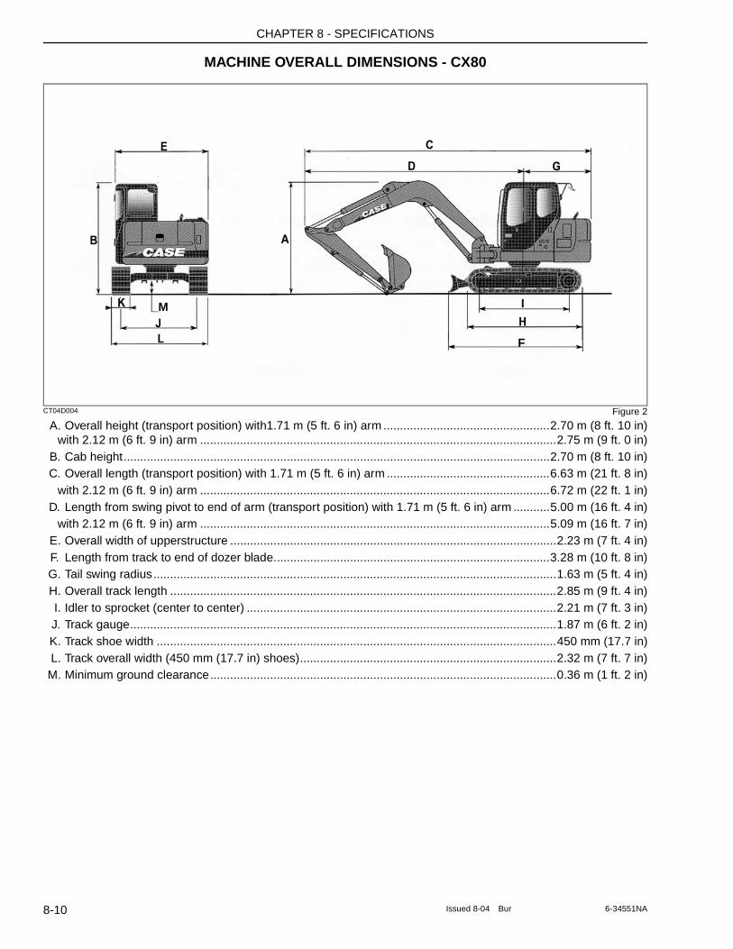
CHAPTER 8 - SPECIFICATIONS
MACHINE OVERALL DIMENSIONS - CX80
CT04D004 Figure 2
A. Overall height (transport position) with1.71 m (5 ft. 6 in) arm ..................................................2.70 m (8 ft. 10 in)with 2.12 m (6 ft. 9 in) arm ...........................................................................................................2.75 m (9 ft. 0 in)
B. Cab height................................................................................................................................2.70 m (8 ft. 10 in)C. Overall length (transport position) with 1.71 m (5 ft. 6 in) arm .................................................6.63 m (21 ft. 8 in)
with 2.12 m (6 ft. 9 in) arm .........................................................................................................6.72 m (22 ft. 1 in)D. Length from swing pivot to end of arm (transport position) with 1.71 m (5 ft. 6 in) arm ...........5.00 m (16 ft. 4 in)
with 2.12 m (6 ft. 9 in) arm .........................................................................................................5.09 m (16 ft. 7 in)E. Overall width of upperstructure ..................................................................................................2.23 m (7 ft. 4 in)F. Length from track to end of dozer blade...................................................................................3.28 m (10 ft. 8 in)G. Tail swing radius.........................................................................................................................1.63 m (5 ft. 4 in)H. Overall track length ....................................................................................................................2.85 m (9 ft. 4 in)I. Idler to sprocket (center to center) .............................................................................................2.21 m (7 ft. 3 in)J. Track gauge................................................................................................................................1.87 m (6 ft. 2 in)K. Track shoe width ........................................................................................................................450 mm (17.7 in)L. Track overall width (450 mm (17.7 in) shoes).............................................................................2.32 m (7 ft. 7 in)M. Minimum ground clearance........................................................................................................0.36 m (1 ft. 2 in)
F
M
8-10 Issued 8-04 Bur 6-34551NA
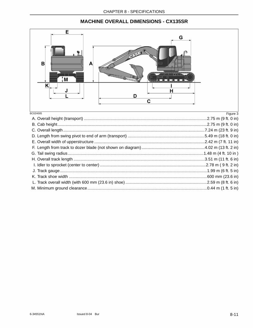
CHAPTER 8 - SPECIFICATIONS
MACHINE OVERALL DIMENSIONS - CX135SR
BC02H005 Figure 3
A. Overall height (transport) ...........................................................................................................2.75 m (9 ft. 0 in)B. Cab height..................................................................................................................................2.75 m (9 ft. 0 in)C. Overall length ...........................................................................................................................7.24 m (23 ft. 9 in)D. Length from swing pivot to end of arm (transport) ...................................................................5.49 m (18 ft. 0 in)E. Overall width of upperstructure ................................................................................................2.42 m (7 ft. 11 in)F. Length from track to dozer blade (not shown on diagram).......................................................4.02 m (13 ft. 2 in)G. Tail swing radius ......................................................................................................................1.48 m (4 ft. 10 in )H. Overall track length ..................................................................................................................3.51 m (11 ft. 6 in)I. Idler to sprocket (center to center) ............................................................................................2.78 m ( 9 ft. 2 in)J. Track gauge................................................................................................................................1.99 m (6 ft. 5 in)K. Track shoe width ........................................................................................................................600 mm (23.6 in)L. Track overall width (with 600 mm (23.6 in) shoe) .......................................................................2.59 m (8 ft. 6 in)M. Minimum ground clearance........................................................................................................0.44 m (1 ft. 5 in)
8-116-34551NA Issued 8-04 Bur
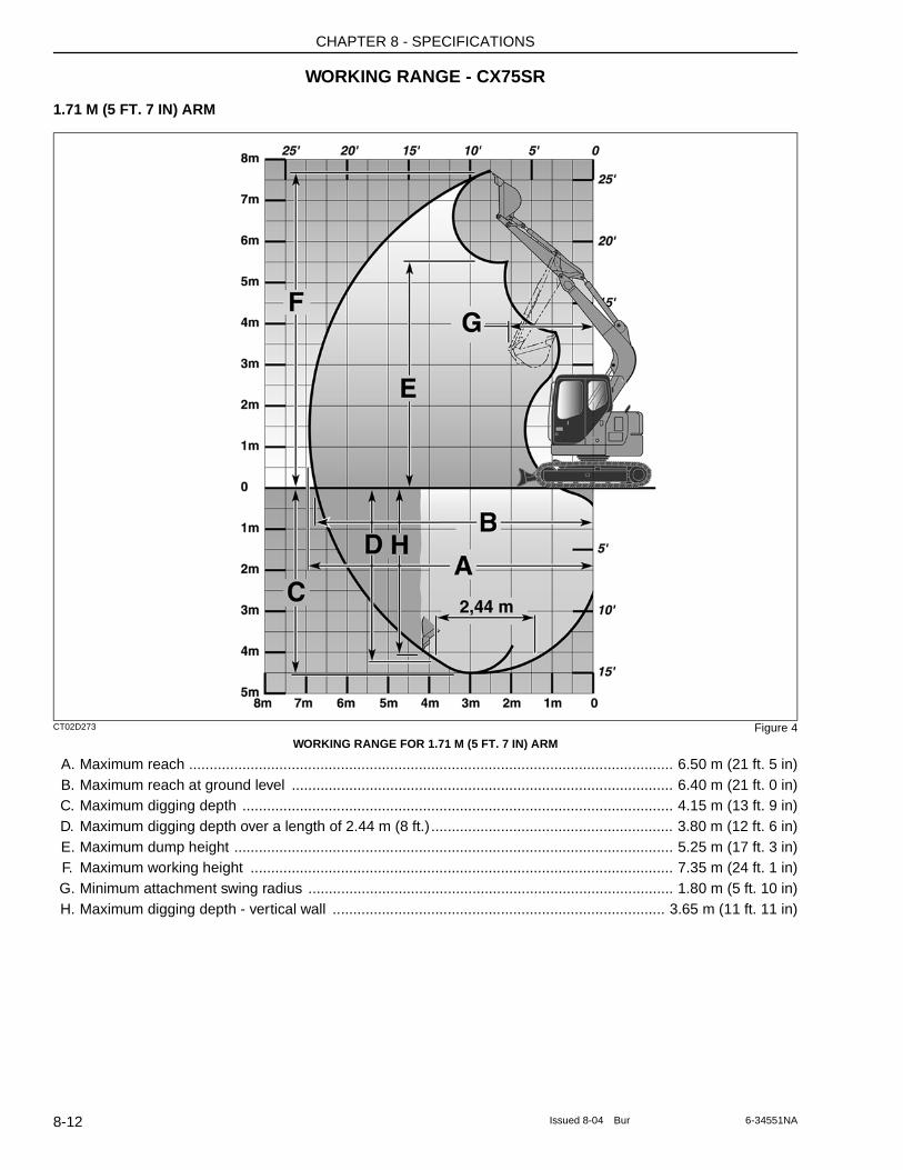
CHAPTER 8 - SPECIFICATIONS
WORKING RANGE - CX75SR
1.71 M (5 FT. 7 IN) ARM
CT02D273 Figure 4WORKING RANGE FOR 1.71 M (5 FT. 7 IN) ARM
A. Maximum reach ...................................................................................................................... 6.50 m (21 ft. 5 in)B. Maximum reach at ground level ............................................................................................. 6.40 m (21 ft. 0 in)C. Maximum digging depth ......................................................................................................... 4.15 m (13 ft. 9 in)D. Maximum digging depth over a length of 2.44 m (8 ft.) ........................................................... 3.80 m (12 ft. 6 in)E. Maximum dump height ........................................................................................................... 5.25 m (17 ft. 3 in)F. Maximum working height ....................................................................................................... 7.35 m (24 ft. 1 in)G. Minimum attachment swing radius ......................................................................................... 1.80 m (5 ft. 10 in)H. Maximum digging depth - vertical wall ................................................................................. 3.65 m (11 ft. 11 in)
8-12 Issued 8-04 Bur 6-34551NA
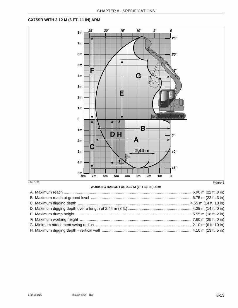
CHAPTER 8 - SPECIFICATIONS
CX75SR WITH 2.12 M (6 FT. 11 IN) ARM
CT02D273 Figure 5WORKING RANGE FOR 2.12 M (6FT 11 IN ) ARM
A. Maximum reach ...................................................................................................................... 6.90 m (22 ft. 8 in)B. Maximum reach at ground level ............................................................................................. 6.75 m (22 ft. 3 in)C. Maximum digging depth ....................................................................................................... 4.55 m (14 ft. 10 in)D. Maximum digging depth over a length of 2.44 m (8 ft.) ........................................................... 4.25 m (14 ft. 0 in)E. Maximum dump height ........................................................................................................... 5.55 m (18 ft. 2 in)F. Maximum working height ....................................................................................................... 7.60 m (25 ft. 0 in)G. Minimum attachment swing radius ......................................................................................... 2.10 m (6 ft. 10 in)H. Maximum digging depth - vertical wall ................................................................................... 4.10 m (13 ft. 5 in)
8-136-34551NA Issued 8-04 Bur
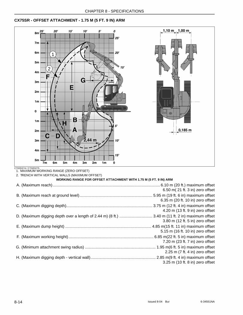
CHAPTER 8 - SPECIFICATIONS
CX75SR - OFFSET ATTACHMENT - 1.75 M (5 FT. 9 IN) ARM
CT02D274 / CT02D2751. MAXIMUM WORKING RANGE (ZERO OFFSET)2. TRENCH WITH VERTICAL WALLS (MAXIMUM OFFSET)
WORKING RANGE FOR OFFSET ATTACHMENT WITH 1.75 M (5 FT. 9 IN) ARM
A. (Maximum reach) ................................................................................................. 6.10 m (20 ft.) maximum offset6.50 m( 21 ft. 3 in) zero offset
B. (Maximum reach at ground level).................................................................. 5.95 m (19 ft. 6 in) maximum offset6.35 m (20 ft. 10 in) zero offset
C. (Maximum digging depth).............................................................................. 3.75 m (12 ft. 4 in) maximum offset4.20 m (13 ft. 9 in) zero offset
D. (Maximum digging depth over a length of 2.44 m) (8 ft.) .............................. 3.40 m (11 ft. 2 in) maximum offset3.80 m (12 ft. 5 in) zero offset
E. (Maximum dump height) .............................................................................. 4.85 m(15 ft. 11 in) maximum offset5.15 m (16 ft. 10 in) zero offset
F. (Maximum working height) ............................................................................. 6.85 m(22 ft. 5 in) maximum offset7.20 m (23 ft. 7 in) zero offset
G. (Minimum attachment swing radius) ................................................................ 1.95 m(6 ft. 5 in) maximum offset2.25 m (7 ft. 4 in) zero offset
H. (Maximum digging depth - vertical wall)........................................................... 2.85 m(9 ft. 4 in) maximum offset3.25 m (10 ft. 8 in) zero offset
1
2
8-14 Issued 8-04 Bur 6-34551NA
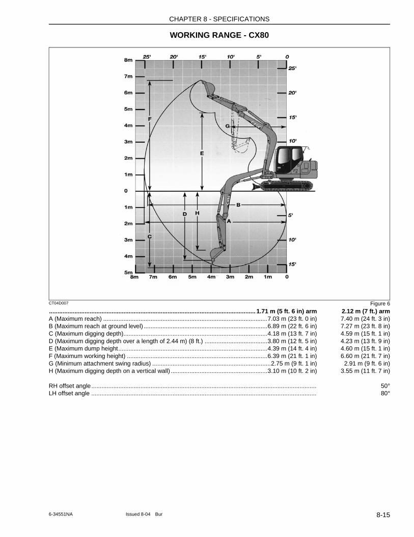
CHAPTER 8 - SPECIFICATIONS
WORKING RANGE - CX80
CT04D007 Figure 6
.......................................................................................................................... 1.71 m (5 ft. 6 in) arm 2.12 m (7 ft.) armA (Maximum reach) .................................................................................................7.03 m (23 ft. 0 in) 7.40 m (24 ft. 3 in)B (Maximum reach at ground level) .........................................................................6.89 m (22 ft. 6 in) 7.27 m (23 ft. 8 in)C (Maximum digging depth).....................................................................................4.18 m (13 ft. 7 in) 4.59 m (15 ft. 1 in)D (Maximum digging depth over a length of 2.44 m) (8 ft.) .....................................3.80 m (12 ft. 5 in) 4.23 m (13 ft. 9 in)E (Maximum dump height........................................................................................4.39 m (14 ft. 4 in) 4.60 m (15 ft. 1 in)F (Maximum working height) ...................................................................................6.39 m (21 ft. 1 in) 6.60 m (21 ft. 7 in)G (Minimum attachment swing radius) ......................................................................2.75 m (9 ft. 1 in) 2.91 m (9 ft. 6 in)H (Maximum digging depth on a vertical wall) .........................................................3.10 m (10 ft. 2 in) 3.55 m (11 ft. 7 in)
RH offset angle..................................................................................................................................... 50°LH offset angle ..................................................................................................................................... 80°
8-156-34551NA Issued 8-04 Bur
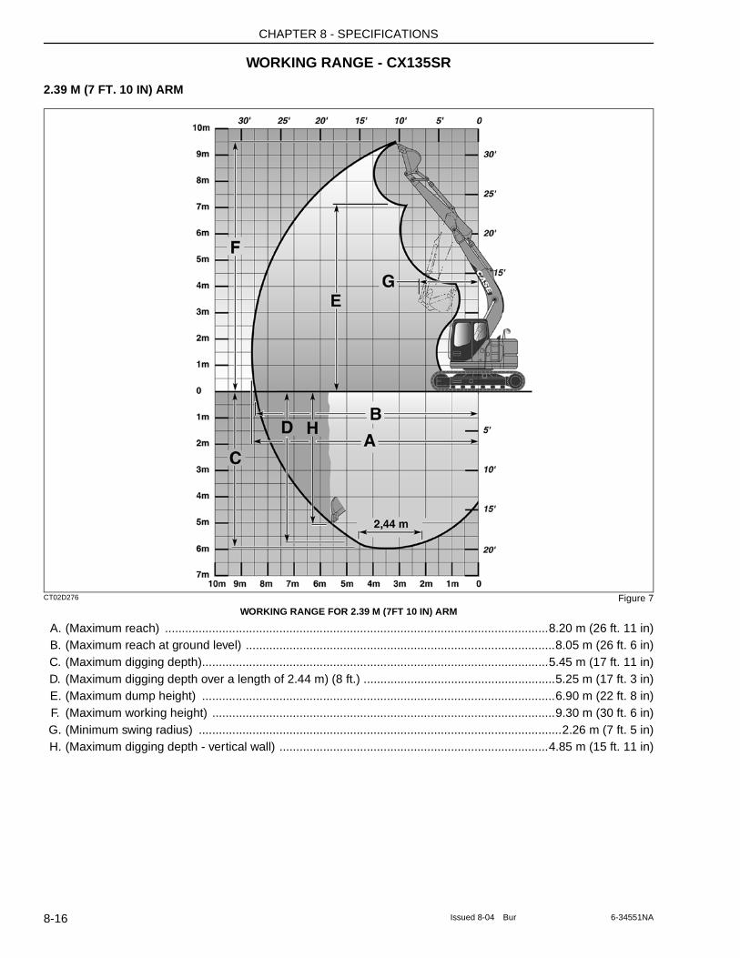
CHAPTER 8 - SPECIFICATIONS
WORKING RANGE - CX135SR
2.39 M (7 FT. 10 IN) ARM
CT02D276 Figure 7WORKING RANGE FOR 2.39 M (7FT 10 IN) ARM
A. (Maximum reach) ..................................................................................................................8.20 m (26 ft. 11 in)B. (Maximum reach at ground level) ............................................................................................8.05 m (26 ft. 6 in)C. (Maximum digging depth).......................................................................................................5.45 m (17 ft. 11 in)D. (Maximum digging depth over a length of 2.44 m) (8 ft.) .........................................................5.25 m (17 ft. 3 in)E. (Maximum dump height) .........................................................................................................6.90 m (22 ft. 8 in)F. (Maximum working height) ......................................................................................................9.30 m (30 ft. 6 in)G. (Minimum swing radius) ............................................................................................................2.26 m (7 ft. 5 in)H. (Maximum digging depth - vertical wall) ................................................................................4.85 m (15 ft. 11 in)
8-16 Issued 8-04 Bur 6-34551NA
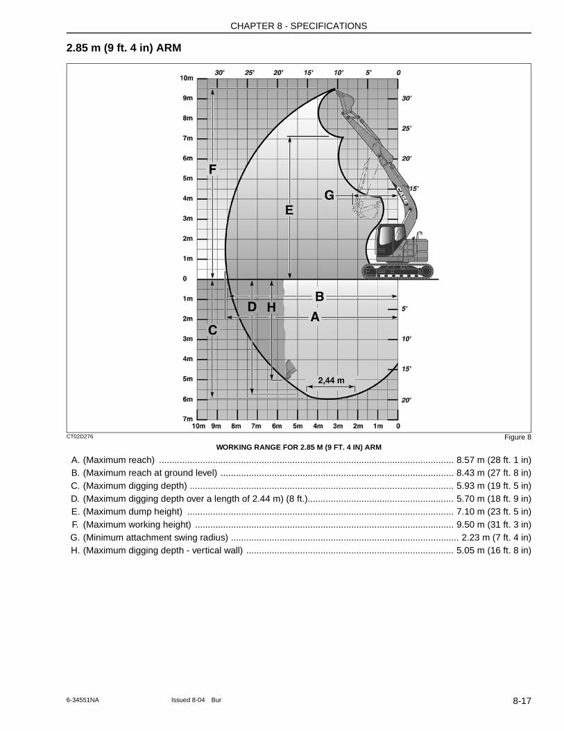
CHAPTER 8 - SPECIFICATIONS
2.85 m (9 ft. 4 in) ARM
CT02D276 Figure 8WORKING RANGE FOR 2.85 M (9 FT. 4 IN) ARM
A. (Maximum reach) ................................................................................................................... 8.57 m (28 ft. 1 in)B. (Maximum reach at ground level) ........................................................................................... 8.43 m (27 ft. 8 in)C. (Maximum digging depth) ....................................................................................................... 5.93 m (19 ft. 5 in)D. (Maximum digging depth over a length of 2.44 m) (8 ft.)......................................................... 5.70 m (18 ft. 9 in)E. (Maximum dump height) ........................................................................................................ 7.10 m (23 ft. 5 in)F. (Maximum working height) ..................................................................................................... 9.50 m (31 ft. 3 in)G. (Minimum attachment swing radius) ......................................................................................... 2.23 m (7 ft. 4 in)H. (Maximum digging depth - vertical wall) ................................................................................. 5.05 m (16 ft. 8 in)
8-176-34551NA Issued 8-04 Bur
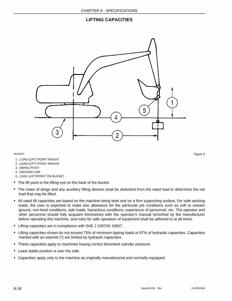
CHAPTER 8 - SPECIFICATIONS
LIFTING CAPACITIES
B9408252 Figure 9
1. LOAD (LIFT) POINT HEIGHT2. LOAD (LIFT) POINT RADIUS3. SWING PIVOT4. GROUND LINE5. LOAD (LIFT)POINT ON BUCKET
• The lift point is the lifting eye on the back of the bucket.
• The mass of slings and any auxiliary lifting devices shall be deducted from the rated load to determine the net load that may be lifted.
• All rated lift capacities are based on the machine being level and on a firm supporting surface. For safe working loads, the user is expected to make due allowance for the particular job conditions such as soft or uneven ground, non-level conditions, side loads, hazardous conditions, experience of personnel, etc. The operator and other personnel should fully acquaint themselves with the operator’s manual furnished by the manufacturer before operating this machine, and rules for safe operation of equipment shall be adhered to at all times.
• Lifting capacities are in compliance with SAE J 1097/IS 10567.
• Lifting capacities shown do not exceed 75% of minimum tipping loads or 87% of hydraulic capacities. Capacities marked with an asterisk (*) are limited by hydraulic capacities.
• These capacities apply to machines having correct bloomiest cylinder pressure.
• Least stable position is over the side.
• Capacities apply only to the machine as originally manufactured and normally equipped.
8-18 Issued 8-04 Bur 6-34551NA
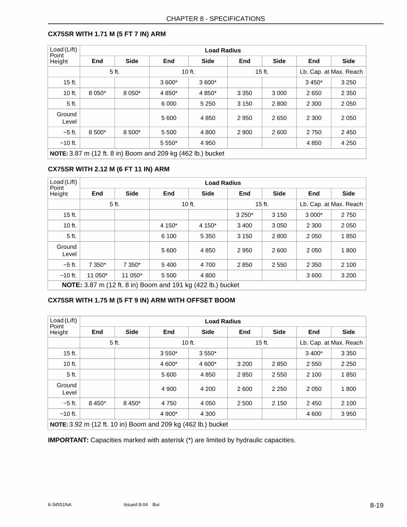
CHAPTER 8 - SPECIFICATIONS
CX75SR WITH 1.71 M (5 FT 7 IN) ARM
CX75SR WITH 2.12 M (6 FT 11 IN) ARM
CX75SR WITH 1.75 M (5 FT 9 IN) ARM WITH OFFSET BOOM
IMPORTANT: Capacities marked with asterisk (*) are limited by hydraulic capacities.
Load (Lift) Point Height
Load Radius
End Side End Side End Side End Side
5 ft. 10 ft. 15 ft. Lb. Cap. at Max. Reach
15 ft. 3 600* 3 600* 3 450* 3 250
10 ft. 8 050* 8 050* 4 850* 4 850* 3 350 3 000 2 650 2 350
5 ft. 6 000 5 250 3 150 2 800 2 300 2 050
Ground Level
5 600 4 850 2 950 2 650 2 300 2 050
−5 ft. 8 500* 8 500* 5 500 4 800 2 900 2 600 2 750 2 450
−10 ft. 5 550* 4 950 4 850 4 250
NOTE: 3.87 m (12 ft. 8 in) Boom and 209 kg (462 lb.) bucket
Load (Lift) Point Height
Load Radius
End Side End Side End Side End Side
5 ft. 10 ft. 15 ft. Lb. Cap. at Max. Reach
15 ft. 3 250* 3 150 3 000* 2 750
10 ft. 4 150* 4 150* 3 400 3 050 2 300 2 050
5 ft. 6 100 5 350 3 150 2 800 2 050 1 850
Ground Level
5 600 4 850 2 950 2 600 2 050 1 800
−5 ft. 7 350* 7 350* 5 400 4 700 2 850 2 550 2 350 2 100
−10 ft. 11 050* 11 050* 5 500 4 800 3 600 3 200
NOTE: 3.87 m (12 ft. 8 in) Boom and 191 kg (422 lb.) bucket
Load (Lift) Point Height
Load Radius
End Side End Side End Side End Side
5 ft. 10 ft. 15 ft. Lb. Cap. at Max. Reach
15 ft. 3 550* 3 550* 3 400* 3 350
10 ft. 4 600* 4 600* 3 200 2 850 2 550 2 250
5 ft. 5 600 4 850 2 850 2 550 2 100 1 850
Ground Level
4 900 4 200 2 600 2 250 2 050 1 800
−5 ft. 8 450* 8 450* 4 750 4 050 2 500 2 150 2 450 2 100
−10 ft. 4 900* 4 300 4 600 3 950
NOTE: 3.92 m (12 ft. 10 in) Boom and 209 kg (462 lb.) bucket
8-196-34551NA Issued 8-04 Bur
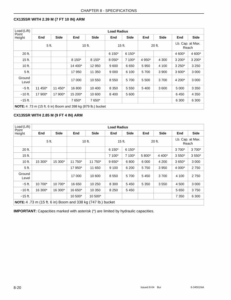
CHAPTER 8 - SPECIFICATIONS
CX135SR WITH 2.39 M (7 FT 10 IN) ARM
CX135SR WITH 2.85 M (9 FT 4 IN) ARM
IMPORTANT: Capacities marked with asterisk (*) are limited by hydraulic capacities.
Load (Lift) Point Height
Load Radius
End Side End Side End Side End Side End Side
5 ft. 10 ft. 15 ft. 20 ft.Lb. Cap. at Max.
Reach
20 ft. 6 150* 6 150* 4 600* 4 600*
15 ft. 8 150* 8 150* 8 050* 7 100* 4 950* 4 300 3 200* 3 200*
10 ft. 14 400* 12 950 9 600 6 650 5 950 4 100 3 250* 3 250
5 ft. 17 950 11 350 9 000 6 100 5 700 3 900 3 600* 3 000
Ground Level
17 000 10 550 8 550 5 700 5 500 3 700 4 200* 3 000
−5 ft. 11 450* 11 450* 16 800 10 400 8 350 5 550 5 400 3 600 5 000 3 350
−10 ft. 17 900* 17 900* 15 200* 10 600 8 400 5 600 6 450 4 350
−15 ft. 7 650* 7 650* 6 300 6 300
NOTE: 4 .73 m (15 ft. 6 in) Boom and 398 kg (879 lb.) bucket
Load (Lift) Point Height
Load Radius
End Side End Side End Side End Side End Side
5 ft. 10 ft. 15 ft. 20 ft.Lb. Cap. at Max.
Reach
20 ft. 6 150* 6 150* 3 700* 3 700*
15 ft. 7 100* 7 100* 5 800* 4 400* 3 550* 3 550*
10 ft. 15 300* 15 300* 11 750* 11 750* 9 650* 6 800 6 000 4 200 3 650* 3 000
5 ft. 17 950* 11 650 9 100 6 200 5 750 3 950 4 000* 2 750
Ground Level
17 000 10 600 8 550 5 700 5 450 3 700 4 100 2 750
−5 ft. 10 700* 10 700* 16 650 10 250 8 300 5 450 5 350 3 550 4 500 3 000
−10 ft. 16 300* 16 300* 16 650* 10 350 8 250 5 450 5 650 3 750
−15 ft. 10 500* 10 500* 7 350 6 300
NOTE: 4 .73 m (15 ft. 6 in) Boom and 338 kg (747 lb.) bucket
8-20 Issued 8-04 Bur 6-34551NA

CHAPTER 8 - SPECIFICATIONS
NOTES
8-216-34551NA Issued 8-04 Bur

CHAPTER 8 - SPECIFICATIONS
8-22 Issued 8-04 Bur 6-34551NA
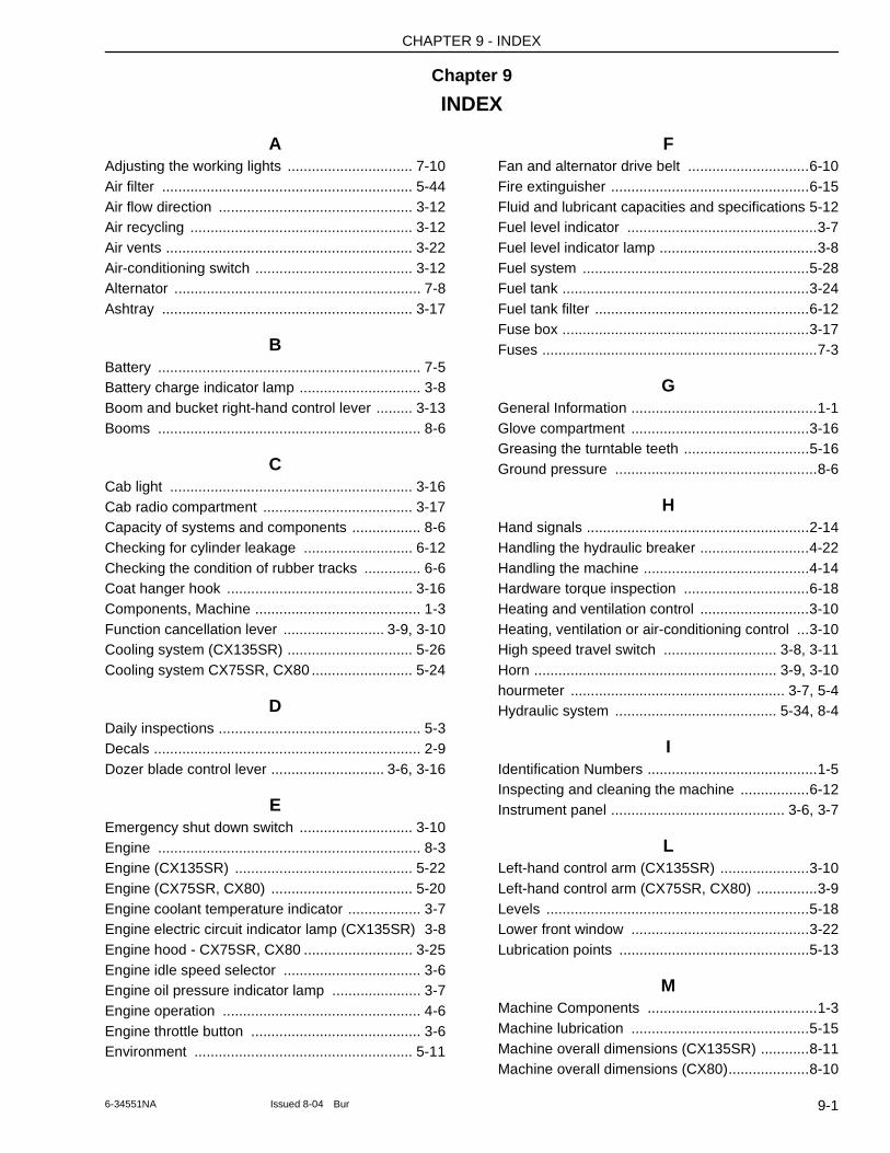
CHAPTER 9 - INDEX
Chapter 9
INDEX
AAdjusting the working lights ............................... 7-10Air filter .............................................................. 5-44Air flow direction ................................................ 3-12Air recycling ....................................................... 3-12Air vents ............................................................. 3-22Air-conditioning switch ....................................... 3-12Alternator ............................................................. 7-8Ashtray .............................................................. 3-17
BBattery ................................................................. 7-5Battery charge indicator lamp .............................. 3-8Boom and bucket right-hand control lever ......... 3-13Booms ................................................................. 8-6
CCab light ............................................................ 3-16Cab radio compartment ..................................... 3-17Capacity of systems and components ................. 8-6Checking for cylinder leakage ........................... 6-12Checking the condition of rubber tracks .............. 6-6Coat hanger hook .............................................. 3-16Components, Machine ......................................... 1-3Function cancellation lever ......................... 3-9, 3-10Cooling system (CX135SR) ............................... 5-26Cooling system CX75SR, CX80 ......................... 5-24
DDaily inspections .................................................. 5-3Decals .................................................................. 2-9Dozer blade control lever ............................ 3-6, 3-16
EEmergency shut down switch ............................ 3-10Engine ................................................................. 8-3Engine (CX135SR) ............................................ 5-22Engine (CX75SR, CX80) ................................... 5-20Engine coolant temperature indicator .................. 3-7Engine electric circuit indicator lamp (CX135SR) 3-8Engine hood - CX75SR, CX80 ........................... 3-25Engine idle speed selector .................................. 3-6Engine oil pressure indicator lamp ...................... 3-7Engine operation ................................................. 4-6Engine throttle button .......................................... 3-6Environment ...................................................... 5-11
FFan and alternator drive belt ..............................6-10Fire extinguisher .................................................6-15Fluid and lubricant capacities and specifications 5-12Fuel level indicator ...............................................3-7Fuel level indicator lamp .......................................3-8Fuel system ........................................................5-28Fuel tank .............................................................3-24Fuel tank filter .....................................................6-12Fuse box .............................................................3-17Fuses ....................................................................7-3
GGeneral Information ..............................................1-1Glove compartment ............................................3-16Greasing the turntable teeth ...............................5-16Ground pressure ..................................................8-6
HHand signals .......................................................2-14Handling the hydraulic breaker ...........................4-22Handling the machine .........................................4-14Hardware torque inspection ...............................6-18Heating and ventilation control ...........................3-10Heating, ventilation or air-conditioning control ...3-10High speed travel switch ............................ 3-8, 3-11Horn ............................................................ 3-9, 3-10hourmeter ..................................................... 3-7, 5-4Hydraulic system ........................................ 5-34, 8-4
IIdentification Numbers ..........................................1-5Inspecting and cleaning the machine .................6-12Instrument panel ........................................... 3-6, 3-7
LLeft-hand control arm (CX135SR) ......................3-10Left-hand control arm (CX75SR, CX80) ...............3-9Levels .................................................................5-18Lower front window ............................................3-22Lubrication points ...............................................5-13
MMachine Components ..........................................1-3Machine lubrication ............................................5-15Machine overall dimensions (CX135SR) ............8-11Machine overall dimensions (CX80)....................8-10
9-16-34551NA Issued 8-04 Bur
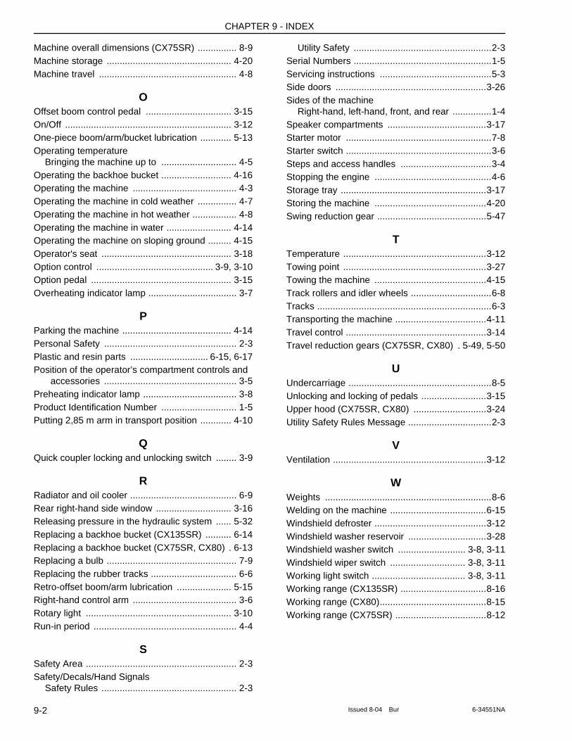
CHAPTER 9 - INDEX
Machine overall dimensions (CX75SR) ............... 8-9Machine storage ................................................ 4-20Machine travel ..................................................... 4-8
OOffset boom control pedal ................................. 3-15On/Off ................................................................ 3-12One-piece boom/arm/bucket lubrication ............ 5-13Operating temperature
Bringing the machine up to ............................. 4-5Operating the backhoe bucket ........................... 4-16Operating the machine ........................................ 4-3Operating the machine in cold weather ............... 4-7Operating the machine in hot weather ................. 4-8Operating the machine in water ......................... 4-14Operating the machine on sloping ground ......... 4-15Operator's seat .................................................. 3-18Option control ............................................. 3-9, 3-10Option pedal ...................................................... 3-15Overheating indicator lamp .................................. 3-7
PParking the machine .......................................... 4-14Personal Safety ................................................... 2-3Plastic and resin parts .............................. 6-15, 6-17Position of the operator’s compartment controls and
accessories ................................................... 3-5Preheating indicator lamp .................................... 3-8Product Identification Number ............................. 1-5Putting 2,85 m arm in transport position ............ 4-10
QQuick coupler locking and unlocking switch ........ 3-9
RRadiator and oil cooler ......................................... 6-9Rear right-hand side window ............................. 3-16Releasing pressure in the hydraulic system ...... 5-32Replacing a backhoe bucket (CX135SR) .......... 6-14Replacing a backhoe bucket (CX75SR, CX80) . 6-13Replacing a bulb .................................................. 7-9Replacing the rubber tracks ................................. 6-6Retro-offset boom/arm lubrication ..................... 5-15Right-hand control arm ........................................ 3-6Rotary light ........................................................ 3-10Run-in period ....................................................... 4-4
SSafety Area .......................................................... 2-3Safety/Decals/Hand Signals
Safety Rules .................................................... 2-3
Utility Safety .....................................................2-3Serial Numbers .....................................................1-5Servicing instructions ...........................................5-3Side doors ..........................................................3-26Sides of the machine
Right-hand, left-hand, front, and rear ...............1-4Speaker compartments ......................................3-17Starter motor ........................................................7-8Starter switch ........................................................3-6Steps and access handles ...................................3-4Stopping the engine .............................................4-6Storage tray ........................................................3-17Storing the machine ...........................................4-20Swing reduction gear ..........................................5-47
TTemperature .......................................................3-12Towing point .......................................................3-27Towing the machine ...........................................4-15Track rollers and idler wheels ...............................6-8Tracks ...................................................................6-3Transporting the machine ...................................4-11Travel control ......................................................3-14Travel reduction gears (CX75SR, CX80) . 5-49, 5-50
UUndercarriage .......................................................8-5Unlocking and locking of pedals .........................3-15Upper hood (CX75SR, CX80) ............................3-24Utility Safety Rules Message ................................2-3
VVentilation ...........................................................3-12
WWeights ................................................................8-6Welding on the machine .....................................6-15Windshield defroster ...........................................3-12Windshield washer reservoir ..............................3-28Windshield washer switch .......................... 3-8, 3-11Windshield wiper switch ............................. 3-8, 3-11Working light switch .................................... 3-8, 3-11Working range (CX135SR) .................................8-16Working range (CX80).........................................8-15Working range (CX75SR) ...................................8-12
9-2 Issued 8-04 Bur 6-34551NA