Embed Size (px)
Citation preview
Document Number 40695
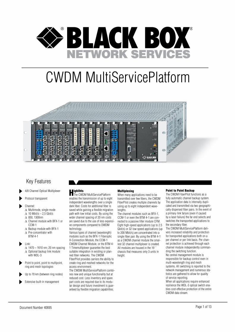
CWDM MultiServicePlatform
Key Features
Page 1 of 13
4/8 Channel Optical Multiplexer
Protocol transparent
Channel:∆ Multimode, single mode∆ 10 Mbit/s – 2,5 Gbit/s∆ 850, 1300nm∆ Channel module with BFX-1 or
CCM-1∆ Backup module with BFX-1∆ Pre-concentrator with
BTM 4-1
Link:∆ 1470 – 1610 nm; 20 nm spacing∆ Optional backup link module
with WDL-3
Point to point, point to multipoint,ring and mesh topologies
Up to 70 km (between ring nodes)
Extensive built-in management
HighlihtsThe CWDM MultiServicePlatform
enables the transmission of up to eightindependent wavelengths over a singledark fiber. Costs for additional fiber issaved while gaining a flexible migrationpath with low initial costs. By using thewider channel spacing of 20 nm costsare saved due to the use of less expensi-ve components compared to DWDMtechnology.Various types of channel (wavelength)modules such as the BFX-1 FiberopticX-Connection Module, the CCM-1CWDM Channel Module, or the BTM 4-1 Timemultiplexer guarantee the bestsuitable integration in existing or plan-ned fiber networks. The CWDMFiberPilot provides carriers the ability tocreate ring and meshed networks for theaccess environment.The CWDM MultiServicePlatform combi-nes new and unique functionality but atreduced cost. Less inventory and sparepart costs are required due to its modu-lar design and future investment is guar-anteed by flexible migration capabilities.
MultiplexingWhen many applications need to betransmitted over few fibers, the CWDMFiberPilot creates multiple channels byusing up to eight independent wave-lengths.The channel modules such as BFX-1,CCM-1 or even the BTM 4-1 are con-nected to a passive filter module CFM.Eight high-speed applications (up to 2.5Gbit/s) or 32 low-speed applications (upto 200 Mbit/s) are concentrated into asingle fiber pair. By using the BTM 4-1as a CWDM channel module the smal-lest 32 channel multiplexer is created.All modules are housed in the 19´´chassis that measures only 3 units inheight.
Point to Point BackupThe CWDM FiberPilot functions as afully automatic channel backup system.The application data is internally dupli-cated and transmitted via two geographi-cally dispersed fiber pairs. In the event ofa primary link failure (even if causedby a laser failure) the far end selects andswitches the transported applications tothe secondary fiber.The CWDM MultiServicePlatform deli-vers increased reliability and protectionfor transported applications both on aper channel or per link basis. Per chan-nel protection is achieved through eachchannel module independently comman-ding the switching function.No central management module isresponsible for backup control even inmulti-wavelength ring and meshsystems. All switching is reported to thenetwork management and numerous sta-tistics are gathered to allow for qualityof service reporting.When all applications require enhancedresilience the WDL-3 optical switch ena-bles cost-effective protection of the entireCWDM data stream.
Document Number 40695 Page 2 of 13
Point to Multipoint (PON)When data needs to be distributed tonumerous destinations from a centralpoint, a passive CWDM Filter Modulecan be positioned at an intermediate hublocation.From the hub location individual fiberscarrying single wavelengths are usedto reach individual end points. At the endpoints small table top products are suffi-cient.
Add/DropThe Add/Drop functionality of the OFX-1is ideal for ring topologies. Incomingdata from the “westbound” link is “drop-ped” and fully 3R regenerated prior tobeing forwarded to the local application.The “added” data from the local applica-tion port is then converted to a CWDMwavelength and sent “eastbound”.The bi-directional functionality of theOFX-1 allows the same Add/Drop perfor-mance for both “westbound“ and“eastbound“ data.
Express (Pass Through)Within multiple CWDM nodes each OFX-1 can be switched from Add/Drop toExpress on the fly. In Express mode“eastbound” data is fully 3R recoveredand forwarded “westbound” to create atransit node on the CWDM ring. Due tothe full signal regeneration virtually unli-mited ring circumferences are possible.Both, “Add/Drop“ and “Express“ setup,can be selected from a remote manage-ment station, which permits adding acustomer on the fly and total flexibility inring configuration (fast provisioning).
Ring BackupBy using the OFX-1 as a channel modulethe CWDM FiberPilot functions as fullyautomatic channel backup system. Theapplication data is internally duplicatedand transmitted onto the “eastbound”and “westbound” fibers. In the event of afiber cut or even a laser failure the farend automatically selects the alternativefiber.The CWDM FiberPilot delivers utmostflexibility and resilience for both point-to-point and ring topologies.
Channel ModulesOFX-1, TDM 4-1 and CCM-1 may usedalternatively or in a mixture
BFX-1Functions — Two channel CWDM con-verter module, Add/Drop, Crossconnect,Express (3R), Backup, 1 slotUser ports — SFP (Small Form FactorPluggable); Multimode, 850nm (VCSEL),1000 – 1250 Mbit/s, LC connector;Single Mode, 1300nm, 1000 – 1250Mbit/s, LC connector; Single Mode,1550nm, 1000 – 1250 Mbit/s, LC con-nectorLink ports — SFP (Small Form FactorPluggable); Single Mode, 1470, 1490,1510, 1530, 1550, 1570, 1590 or 1610nm, LC connector (for more details plea-se refer to OFX-1 data sheet)
BTM 4-1Functions — Four channel TimeDivision Multiplexer, Backup, 1 slotUser ports — Multimode, 850nm, 100– 155 Mbit/s, LC connector; Multimode,1300nm, 100 – 200 Mbit/s, LC connec-torLink ports — SFP (Small Form FactorPluggable); Single Mode, 1470, 1490,1510, 1530, 1550, 1570, 1590 or 1610nm, LC connector (for more details plea-se refer to TDM 4-1 data sheet)
CCM-1 Functions — One channel CWDMconverter module, 1 slotUser port — Multimode, 1300nm, 10– 266 Mbit/s, SC connector; Multimode,850nm, 10 – 155 Mbit/s, SC connector;Multimode, 1300nm, 100 – 622 Mbit/s,SC connector; Multimode, 850nm(VCSEL), 100 – 1250 Mbit/s, SC con-nector; Single Mode, 1300nm, 100 –1250 Mbit/s, SC connector; SingleMode, 1300nm, 10 – 155 Mbit/s, SCconnector; Single Mode, 1300nm, 1000– 2488 Mbit/s, SC connectorLink port — Single Mode, 1470, 1490,1510, 1530, 1550, 1570, 1590 or 1610nm, SC connector
Filter ModulesCFM 4-1 Mux: 4 channel multiplexer,SC connector, 1 slot (demux at remoteside required)CFM 4-1 Demux: 4 channel demulti-plexer, SC connector, 1 slot (mux atremote side required)CFM 8-1 Mux: 8 channel multiplexer,LC connector, 1 slot (demux at remoteside required)CFM 8-1 Demux: 8 channel demulti-plexer, LC connector, 1 slot (mux atremote side required)CFM 4-2 Mux/Demux: 4 channel mul-tiplexer and demultiplexer, LC connector,1 slot (under development)
SpecificationsCFM 8-2 Mux/Demux: 8 channel mul-tiplexer and demultiplexer, LC connector,1 slot (under development)
Backup ModuleWDL – 3 (optional): Common Link
Backup Module, automatic backup swit-ching (Individual Channel backup withOFX-1 or TDM 4-1. Use WDL-3 to bak-kup entire CWDM datalink.)
MultiServicePlatform Rack19´´ chassis, including one PowerSupply, 11 active plus 1 passive slotsDimensions (H x W x D)Rack — 134 x 482 x 370 mm (3 HU)Module —129 x 25 x 190 mmDesigned to be mounted in 19´´ cabinetPower SupplySlide-in supply with integrated fan(2nd PS recommended)Input — 115 – 230 V AC, 50/60 Hz,Power Factor CorrectionFuse — EU: 250 V/4 A (slow)Output — 5 V/ 40 A (200 W)Fan UnitExternal 19´´ unit (1 HU), includingPower Supply (one required perFiberPilot)NMS-1(optional Network Management Module)Functions — SNMP interface, integra-ted webserver, 10BaseT access via RJ45Network Management Module
Patch CablesInterconnection between ChannelModules and Filter Modules (one perchannel required)9/125 Single Mode, duplex, SC–SC, 1m;9/125 Single Mode, duplex, SC–LC, 1m;9/125 Single Mode, duplex, LC–LC, 1m
EnvironmentTemperatureOperating — 0– 40 °C, noncondensingStorage — 0 – 70 °CData Rates 10 Mbit/s – 2.5 Gbit/sTypical Protocols ESCON, ATM, FibreChannel, FICON, SDH, SONET, FastEthernet, Gigabit EthernetTypical Applications SAN, IBM Host,Data Save, LAN, Carrier Access,BroadcastingSafety and Relevant Standards CEconform, FCC part 15, DOC, CDRH 21CFR 1040, Laser Class I Product, (UL,cUL listing pending)
Ordering informationITEM CODEMSP-Rack, 11 Slot, 19”230VAC . . . . . . . . . . . . . . . . . . . . . . . . . . . . . . . . . . . . . . . . .LHS800AE48VDC . . . . . . . . . . . . . . . . . . . . . . . . . . . . . . . . . . . . . . .LHS800AE-48
Optional BMS-1 Management-CardSNMP/Web Management- and LAN-interface . . . . . . . . .LHS800C-NMS
Optional BFM 2/4/8-2 CWDM-Cards, passiv Mux/Demux-Card,1 Slot2-Channel, (1530 and 1550nm SFP required) . . . . . . . . . . . .LHS808C-44-Channel, (1510, 1530, 1550 and 1570 nm SFP required) . .LHS808C-48-Channel, (1470, 1490, 1510, 1530, 1550, 1570, 1590 and 1610 nmSFP required) . . . . . . . . . . . . . . . . . . . . . . . . . . . . . . . . . . . .LHS808C-8
Document Number 40695 Page 3 of 13
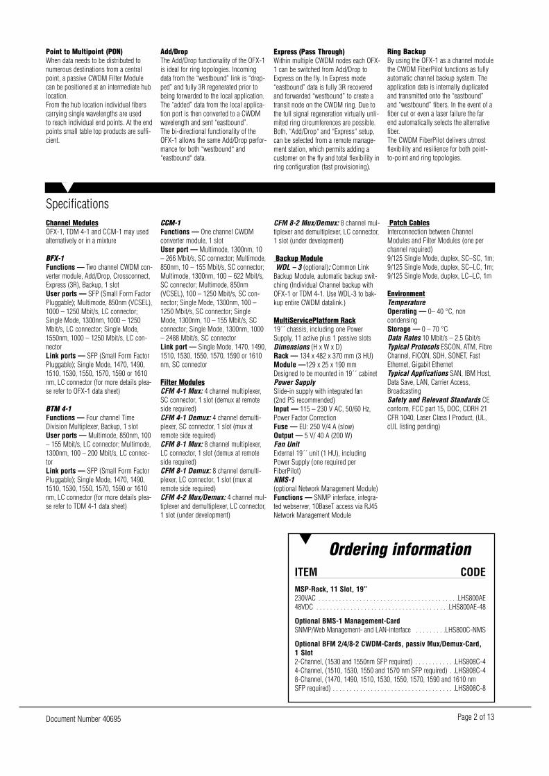
BFX-1 Fiberoptic X-ConnectionKey Features
Optical Cross Connect Module∆ Converter, Booster, Backup,
Repeater∆ Double CWDM channel module,∆ Add/Drop module, Express
channel
Dynamic switching via NMS
Application and link ports:∆ Small Form Factor LC
(pluggable)∆ Multimode, single mode∆ 850, 1300, CWDM: 1470 –
1610 nm∆ 10 Mbit/s – 1,25 Gbit/s
HighlightsThe BFX-1 Optical Fiber X-
Connection is a multifunctional modulefor the MultiServicePlatform. Its fouroptical interfaces can be interconnectedvia network management enablingvarious individual functions. Optional 3Rregeneration functionality can extenddata transmission over long distancesand facilitate the deployment of ringtopologies with multiple nodes.New features, such as Priority Backup,Drop and Continue and dynamic swit-ching from Add/Drop mode to Expressmode provide new and unique opportu-nities for optical networking. Currentcostly functions, mainly known in theWAN environment, are supported by theBFX-1 and are now available for accessapplications.The BFX-1 combines new and uniquefunctionality but at reduced cost. Lessinventory and spare part costs are requi-red and future investment is guaranteedby flexible migration capabilities.
Double Converter, CWDM ChannelThe four optical interfaces allow theBFX-1 to be used as a dual channel sin-gle mode to multimode converter.Two independent multimode applicationsare converted to any wavelength indivi-dually. The field upgradable pluggablelaser modules allow, short reach, longreach or even CWDM selected wave-lengths to be specified. The optional 3Rfunction optimises the optical signalsprior to forwarding to the application andallows maximum distances to be achie-ved.
Priority BackupPriority Backup is a variation of theregular backup function.Using the fourth port of the BFX-1 asecond application can be transmittedover the backup path allowing the nor-mally unused backup fiber to become adata channel. Upon a failure of the pri-mary link the secondary application isterminated in lieu of the main applica-tion. If the backup path fails an alarm isgenerated but the secondary applicationis not recovered, leaving the main appli-cation up and running.
Cross ConnectThe BFX-1 may used for point-to-multi-point operation.When data are transported to variousdestinations from a central point theBFX-1 is configured in the double con-verter mode. In case data need to changetheir destination the BFX-1 operates as across and interlinks the opposite interfa-ces.Drop and ContinueThis mode is suitable when unidirectio-nal data need to be multicasted to manyreceivers.The network is setup as a linear openring. Application data that enters the net-work is made available (dropped) atevery intermediate node and is also fully3R reshaped and forwarded to the nextnode. A typical application for this modeis video broadcasting, whereby manybase station are fed with the same videosignal.
Add/Drop FunctionThe Add/Drop functionality is ideal forring topologies. Incoming data from the“westbound” link is “dropped” and fully3R regenerated prior to being forwardedto the local application.The “added” data from the local applica-tion port is then converted to a CWDMwavelength and sent “eastbound”. Thebi-directional functionality of the BFX-1allows the same Add/Drop performancefor both “westbound” and “eastbound”data.
Express ChannelEach BFX-1 can be switched fromAdd/drop to Express on the fly. InExpress mode “eastbound” data are fully3R recovered and forwarded “west-bound” to create a transit node on thering. Due to the full signal regenerationvirtually unlimited ring circumferencesare made possible.Both, “Add/Drop” and “Express” setup,can be selected from a remote manage-ment station, which permits adding acustomer on the fly and total flexibility inring configuration (fast provisioning).
Backup FunctionThe BFX-1 functions as fully automaticbackup system when equipped with threeor four interfaces.The application data is internally dupli-cated and transmitted onto two geogra-phically dispersed dark fibers. In theevent of a primary link failure (even ifcaused by a laser failure) the far endselects a secondary fiber.Switching is autonomously controlled byeach BFX-1 providing low latency andincreased reliability. No central manageris responsible for backup control, evenin multi-wavelength ring and meshsystems. All switching is reported to thenetwork management and numerous sta-tistics are gathered to allow for quality ofservice reporting. The BFX-1 deliversutmost flexibility and resilience for bothpoint-to-point and ring topologies.
Bandwith control function
3R function for extended distances
Point to point, point to multipoint,ring and mesh topologies
Up to 70 km (between ring nodes)
Table Top, Rack version
Dot matrix function display
Extensive built-in management
Document Number 40695 Page 4 of 13
Optional InterfacesSFP (Small Form Factor Pluggable)
SFP MM/LC/850/1250Multimode, 850 nm (VCSEL), 1000 –1250 Mbit/s, LC connector;Tx Power - 9 dBm min/- 4 dBm max;Rx Sensitivity- 17 dBm/Saturation- 3 dB
SFP SM/LC/1300/1250/SSingle Mode, 1300 nm, 1000 – 1250Mbit/s, LC connector, (typ. 10 km);Tx Power - 11dBm min/- 3 dBm max;Rx Sensitivity- 20 dBm/Saturation- 3 dB
SFP SM/LC1300/1250/LSingle Mode, 1300 nm, 1000 – 1250Mbit/s, LC connector, (typ. 30 km); TxPower - 4 dBm min/+ 1dBm max; RxSensitivity - 20 dBm/Saturation -3 dB
SFP SM/LC/1550/1250/VSingle Mode, 1550 nm, 1000 – 1250Mbit/s, LC connector, (typ. 70 km);Tx Power - 3 dBm min/+ 2 dBm max;Rx Sensitivity- 23 dBm/Saturation- 3 dB
SFP SM/LC/1xxx/1250/VSingle Mode, 1470, 1490, 1510, 1530,1550, 1570, 1590, 1610 nm, 1250Mbit/s, LC connector, (typ. 70 km);Tx Power - 3 dBm min/2 dBm max;Rx Sensitivity- 23 dBm/Saturation- 3 dB
Data Rates10 Mbit/s - 1.25Gbit/s
Typical ProtocolsESCON, ATM, Fibre Channel, FICON,SDH, SONET, Fast Ethernet, GigabitEthernet
Typical ApplicationsSAN, IBM Host, Data Save, LAN, CarrierAccess, Broadcasting
SpecificationsTest Functionindependent Loop function for all interfa-ces via front panel or Windows Managerwith automatic Time OutLoss of Signal for all interfaces
Power Supply Table TopInput — 100 - 240 V AC, 50/60 Hz, 60- 72 VAOutput — 5 V DC, 4A (typ. Currentbelow 2 A)
Power Supply RackSlide-in supply with integrated fan Input —115 - 230 V AC, 50/60 Hz,Power Factor CorrectionFuse —EU: 250 V / 4A (slow) Output — 5 V / 4A (200 W)
EnvironmentTemperatureOperating — 0– 40 °C, noncondensingStorage — 0 – 70 °C
Dimensions (H x W x D)Table Top Unit — 37 x 103 x 170 mmRack Module — 129 x 25 x 190 mmComplete Rack —134 x 482 x 370 mm,Designed to be mounted in 19” cabinet.
Safety and relevant StandardsCE conform, FCC part 15, DOC, CDRH21 CFR 1040, Laser Class I Product(UL, cUL listing pending)
Ordering informationITEM CODEBFX-1 Fiberoptic X-Connection (SFPs not incl.) 4 x SFP, up to2.5 GbpsTable Top . . . . . . . . . . . . . . . . . . . . . . . . . . . . . . . . . . . . . . . .LHS802AEMSP-Rack Card . . . . . . . . . . . . . . . . . . . . . . . . . . . . . . . . . . . .LHS802C
BFX-1/3r Fiberoptic X-Connection with 3R-Function (SFPs notincl.) 4 x SFP, up to 2.5 Gbps, 3R-FunctionTable Top . . . . . . . . . . . . . . . . . . . . . . . . . . . . . . . . . . . . .LHS802AE-3RMSP-Rack Card . . . . . . . . . . . . . . . . . . . . . . . . . . . . . . . . .LHS802C-3R
Document Number 40695 Page 5 of 13
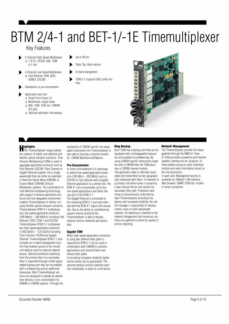
BTM 2/4-1 and BET-1/-1E TimemultiplexerKey Features
2 Channel High Speed Multiplexer∆ 1 G FC, FICON, GbE, TDM
4-1 link
4 Channel Low Speed Multiplexer∆ Fast Ethernet, ATM, SDH,
SONET, ESCON
Standalone or pre-concentrator
Application and link:∆ Small Form Factor LC∆ Multimode, single mode∆ 850, 1300, 1550 nm, CWDM
ITU grid∆ Optional automatic link backup
HighlightsThe Timemultiplexer range enables
the creation of highly cost-effective andflexible optical transport solutions. TimeDivision Multiplexing (TDM) is used toaggregate application protocols such asFast Ethernet, ESCON, Fibre Channel orGigabit Ethernet together into a singlewavelength that can either be extendedor feed into Dense Wave (DWDM) orCoarse Wave (CWDM) DivisionMultiplexer systems. The combination ofcost-effective multiplexing technologywith support of diverse application pro-tocols and hot-swappable transceiversenables Timemultiplexer to deliver uni-quely flexible optical transport solutions. Timemultiplexer BTM 4-1 multiplexesfour low-speed application protocols(100 Mbit/s – 200 Mbit/s) including FastEthernet, FDDI, STM-1 and ESCON.Timemultiplexer BTM 2-1 multiplexestwo high-speed application protocols(1.062 Gbit/s – 1.25 Gbit/s) includingFibre Channel, FICON and GigabitEthernet. Timemultiplexer BTM 2-1 alsoincludes an in-band management func-tion that enables access to the remoteunit without need for external networkaccess. Optional protection switchingfrom the primary fiber to a secondaryfiber is supported through a field upgra-deable backup port that can be enabledwith a software key and an additionaltransceiver. Both Timemultiplexer ver-sions are designed to operate as standa-lone devices or pre-concentrators forDWDM or CWDM systems. Through the
availability of CWDM specific hot-swap-pable transceivers the Timemultiplexer isalso able to become a channel modulefor CWDM MultiServicePlatform.
Pre-ConcentratorIn some circumstances it is necessaryto extend low-speed application proto-cols (100 Mb/s – 200 Mb/s) such asESCON or Fast Ethernet with a GigabitEthernet application to a remote site. TheBTM 4-1 pre-concentrates up to fourlow-speed applications and feeds intoone port of the BTM 2-1.The Gigabit Ethernet is connected tothe remaining BTM 2-1 port and exten-ded with the BTM 4-1 data to the remotesite. Due to the ability to costeffectivelysupport diverse protocols theTimemultiplexer is able to flexiblyenhance various networks and topolo-gies.
Gigabit TDMWhen high-speed application connectivi-ty using two different fiber paths isrequired the BTM 2-1 can be used incombination with CWDM to combineapplications and transmit them overdiverse fiber paths.In providing increased reliability higherservice levels can be guaranteed. Theoptional backup function switches eachlink individually in event of a link failure.
Ring BackupEach TDM has a backup port that can beequipped with a hotswappable transcei-ver and enabled via software key. Byusing CWDM specific transceivers toget-her with a CWDM filter the TDM beco-mes a CWDM channel module.The application data is internally dupli-cated and transmitted via two geographi-cally dispersed dark fibers. In theevent ofa primary link failure (even if caused bya laser failure) the far end selects thesecondary fiber path. Protection swit-ching is autonomously controlled byeach Timemultiplexer providing lowlatency and increased reliability. No cen-tral manager is responsible for backupcontrol, even in multi-wavelengthsystems. All switching is reported to thenetwork management and numerous sta-tistics are gathered to allow for quality ofservice reporting.
Network ManagementThe Timemultiplexer provide full mana-geability through the NMS b1 View.b1 View provides a powerful and intuitiveoperator interface for all products. b1View enables access to each individualmodule and reads information stored onthe microprocessorin each card. Management access isavailable via 10BaseT LAN interface,Web browser, SNMP, ISDN S0, modemor serial connection.
Up to 90 km
Table Top, Rack version
In-band mangament
TDM 2-1 supports GbE jumbo fra-mes
Document Number 40695 Page 6 of 13
TimemultiplexerTime Division MultiplexerMultirate, Automatic Link Backup (viasoftware key), Jumbo Frame Support atTDM 2-1
BTM 2-1/x-A/SFP -B/SFP -L/SFP2 Channel TDM with two applicationports, link port and backup link portApplications: Fibre Channel, FICON,Gigabit Ethernet, TDM 4-1 LinkFor port specifications refer to sectionPluggable Optical Interfaces
BTM 4-1/xS-A/MM/LC/1300/200 -L/SFP4 Channel TDM with four applicationports, link port and backup link portApplications: Fast Ethernet, ATM OC-3,SDH STM-1, ESCONMultimode, 1300 nm, 100 – 200 Mbit/s,LC connectorTx Power - 19 dBm min/- 14 dBm maxRx Sensitivity - 30 dBm/Saturation - 14dB
BTM 4-1/R/ES-A/MM/LC/1300/200 -L/SFP4 Channel ESCON TDM with four appli-cation ports, link port and backup linkport; Multimode, 1300 nm, 200 Mbit/s,LC connector; Tx Power - 19 dBm min/-14 dBm max; Rx Sensitivity - 30dBm/Saturation - 14 dB
Pluggable Optical InterfaceSFP (Small Form Factor Pluggable)
SFP MM/LC/850/1250Multimode, 850 nm (VCSEL), 1000 –1250 Mbit/s, LC connector;Tx Power - 9 dBm min/- 4 dBm max;Rx Sensitivity- 18 dBm/Saturation- 3 dB
SFP SM/LC/1300/1250/SSingle Mode, 1300 nm, 1000 – 1250Mbit/s, LC connector, (typ. 10 km)*;Tx Power - 9 dBm min/- 3 dBm max;Rx Sensitivity- 20 dBm/Saturation- 3 dB
SFP SM/LC/1300/1250/LSingle Mode, 1300 nm, 125 – 1250Mbit/s, LC connector, (typ. 30 km)*;Tx Power - 4 dBm min/+ 1 dBm max;Rx Sensitivity- 21 dBm/Saturation- 3 dB
SpecificationsSFP SM/LC/1550/1250/VSingle Mode, 1550 nm, 50 – 1250Mbit/s, LC connector, (typ. 70 km)*;Tx Power - 3 dBm min/+ 2 dBm max;Rx Sensitivity- 23 dBm/Saturation- 3 dB
SFP SM/LC/1300/2500/SSingle Mode, 1300 nm, 155 – 2500Mbit/s, LC con., (typ. 10 km, 2 km OC-48)*;Tx Power - 9 dBm min/- 3 dBm max;Rx Sensitivity - 20 dBm (2G)/ - 18 dBm(2.5G)/Saturation - 3 dB
SFP SM/LC/C1xxx/2500/VSingle Mode, CWDM: 1470, 1490, 1510,1530, 1550, 1570, 1610 nm,125 – 2500 Mbit/s, LC connector, (typ.70 km)*;Tx Power + 0 dBm min/+ 5 dBm max;Rx Sensitivity - 23 dBm (1 G)/- 21 dBm(2.5 G)/Saturation + 0 dB
MultiServicePlatform RackRequired for TimePilot rack version,common rack for all rack modulesIncludes Power Supply and NetworkTermination module for serial access
Network Management ModuleSNMP interface, integrated webserver,10BASE-T access via RJ45
Power Supply Table TopInput — 100 - 240 V AC, 50/60 Hz, 60- 72 VAOutput — 5 V DC, 4A (typ. Currentbelow 2 A)
Power Supply RackSlide-in supply with integrated fan Input —115 - 230 V AC, 50/60 Hz,Power Factor CorrectionFuse —EU: 250 V / 4A (slow) Output — 5 V / 4A (200 W)
Dimensions (H x W x D)Table Top Unit — 37 x 103 x 170 mmRack Module — 129 x 25 x 190 mmComplete Rack —134 x 482 x 370 mm (3 HU),Designed to be mounted in 19” cabinet.
Safety and relevant StandardsCE conform, FCC part 15, DOC, CDRH21 CFR 1040, Laser Class I Product(UL, cUL listing pending) 47
Ordering informationITEM CODEBTM 4-1 TDM (SFPs not incl.), 4x Applicationsport MM 1300nmLC, 1+1x Linkport SFPTable Top . . . . . . . . . . . . . . . . . . . . . . . . . . . . . . . . . . . . . . . .LHS803AEMSP-Rack Card, 1 Slot . . . . . . . . . . . . . . . . . . . . . . . . . . . . . .LHS803C
BTM 2-1 Highspeed-TDM (SFPs not incl.), 2x Entryport SFP,1+1x Linkport SFPTable Top . . . . . . . . . . . . . . . . . . . . . . . . . . . . . . . . . . . . . . . .LHS804AEMSP-Rack Card, 1 Slot . . . . . . . . . . . . . . . . . . . . . . . . . . . . . .LHS804C
BET-1, 4x Entryport RD45, 1 x Linkport SFPTable Top . . . . . . . . . . . . . . . . . . . . . . . . . . . . . . . . . . . . . . . .LHS805AEMSP-Rack Card, 1 Slot . . . . . . . . . . . . . . . . . . . . . . . . . . . . . .LHS805C
BET-1E, 5x Entryport RJ45, 1x Entryport RJ11, 1x Linkport SFPMSP-Rack Card, 1 Slot . . . . . . . . . . . . . . . . . . . . . . . . . . . . . .LHS806C
Document Number 40695 Page 7 of 13
BFC-2 FiberopticConverter
Key Features
Optical Fiber Converter∆ Multimode, single mode∆ 850, 1300, 1550nm and CWDM
Optical Repeater & Booster∆ Clock recovery function (3R)
50 Mbit/s - 2.67 Gbit/s
Pluggable transceivers
Up to 120 km
Bandwith control function
Test loop
Table Top, Rack version
Extensive built-in management
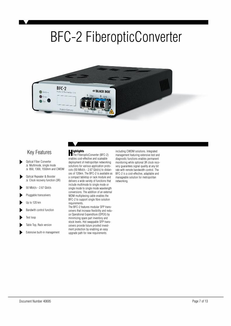
HighlightsThe FiberopticConverter (BFC-2)
enables cost-effective and scaleabledeployment of metropolitan networkingsolutions for various application proto-cols (50 Mbit/s - 2.67 Gbit/s) to distan-ces of 120km. The BFC-2 is available asa compact tabletop or rack module anddelivers a wide variety of functions thatinclude multimode to single mode orsingle mode to single mode wavelengthconversions. The addition of an externalWDM multiplexing cable enables theBFC-2 to support single fibre solutionrequirements.The BFC-2 features modular SFP trans-ceivers that increase flexibility and redu-ce Operational Expenditure (OPEX) byminimizing spare part inventory andstock levels. Hot swappable SFP trans-ceivers provide future proofed invest-ment protection by enabling an easyupgrade path for new requirements
including CWDM solutions. Integratedmanagement featuring extensive test anddiagnostic functions enables permanentmonitoring while optional 3R clock reco-very guarantees signal quality at any bitrate with remote bandwidth control. TheBFC-2 is a cost-effective, adaptable andmanageable solution for metropolitannetworking.
Document Number 40695 Page 8 of 13
Optical InterfaceSFP (Small form Factor Pluggable)(for detailed optical data please refer toSFP technical Information)
SFP MM/LC/1300/266Multimode, 1300 nm, 50 – 266 Mbit/s,LC connector;
SFP MM/LC/1300/622Multimode, 1300 nm, 50 - 700 Mbit/s,LC connector
SFP SM/LC/1300/266/SSinglemode, 1300 nm, 50 – 266 Mbit/s,LC connector, (typ. 15 km)*
SFP SM/LC/1300/622/SSingle Mode, 1300 nm, 50 – 700Mbit/s, LC connector, (typ. 2 km)*
SFP SM/LC/1550/1250/LSingle Mode, 1550 nm, 50 – 1300Mbit/s, LC connector, (typ. 40 km)*
SFP SM/LC/1550/1250/VSingle Mode, 1550 nm, 50 – 1300Mbit/s, LC connector, (typ. 70 km)*
SFP SM/LC/1300/2125Singlemode, 1300 nm, 1000 – 2125Mbit/s, LC connector (typ. 10km)
SFP MM/LC/850/2125Multimode, 850 nm, 1000 – 2125Mbit/s, LC connector
SFP SM/LC/1300/2500/SSingle Mode, 1300 nm, 155 – 2670Mbit/s, LC connector, (typ. 10 km, 2kmOC-48)*
SFP SM/LC/C1xxx/1250/VSingle Mode, CWDM, 50 - 1300 Mbit/s,LC connector, (typ. 70 km)*
SFP SM/LC/C1xxx/2500/VSingle Mode, CWDM, 125 – 2670Mbit/s, LC connector, (typ. 70 km)*
SFP SM/LC/C1xxx/2500/USingle Mode, CWDM, 125 – 2670Mbit/s, LC connector, (typ. 90 km)*
Data Rates50 Mbit/s - 2.5 Gbit/s (2.488 Gbit/srequires 3R function)Typical ProtocolsSDH, SONET, ATM, Gigabit Ethernet,Fast Ethernet, Fibre Channel, FICON
SpecificationsTypical ApplicationsCarrier Access, LAN Extension, SAN,Broadcasting, Data Save
Diagnostic FunctionsLaser failure of every port, temperatureand operating voltage status Opticalpower levels, Traps and statistics Loopsetting Connection to NetworkManagement System (Terminal orSEEmiles)
BFC-2 Versions- Table Top standard version- Table Top version with 3R function (for2.488 Gbit/s or long distances)- Rack standard version- Rack version with 3R function (for2.488 Gbit/s or long distances)
MultiServicePlatformRequired for BFC-2 rack version, com-mon rack for all rack modulesIncludes Power Supply and NetworkTermination module for serial access
Network Management ModuleSNMP interface, integrated webserver,10BASE-T access via RJ45
Power Supply Table TopInput — 100 - 240 V AC, 50/60 Hz, 60- 72 VAOutput — 5 V DC, 4A (typ. Currentbelow 2 A)
Power Supply RackSlide-in supply with integrated fan Input —115 - 230 V AC, 50/60 Hz,Power Factor CorrectionFuse —EU: 250 V / 4A (slow) Output — 5 V / 4A (200 W)
Dimensions (H x W x D)Table Top Unit — 37 x 103 x 170 mmRack Module — 129 x 25 x 190 mmComplete Rack —134 x 482 x 370 mm (3 HU),Designed to be mounted in 19” cabinet.
Safety and relevant StandardsCE conform, FCC part 15, DOC, CDRH21 CFR 1040, Laser Class I Product(UL, cUL listing pending)
Ordering informationITEM CODEBFC-2 FiberopticConverter (SFPs not incl.), 2 x SFPTable Top . . . . . . . . . . . . . . . . . . . . . . . . . . . . . . . . . . . . . . . .LHS801AEMSP-Rack Card, Slot . . . . . . . . . . . . . . . . . . . . . . . . . . . . . . . .LHS801C
BFC-2/3-3R FiberopticConverter with 3R-Function (SFPS notincl.), 2 x SFP, 3R-FunctionTable Top . . . . . . . . . . . . . . . . . . . . . . . . . . . . . . . . . . . . .LHS801AE-3RMSP-Rack Card, Slot . . . . . . . . . . . . . . . . . . . . . . . . . . . . .LHS801C-3R
Document Number 40695 Page 9 of 13
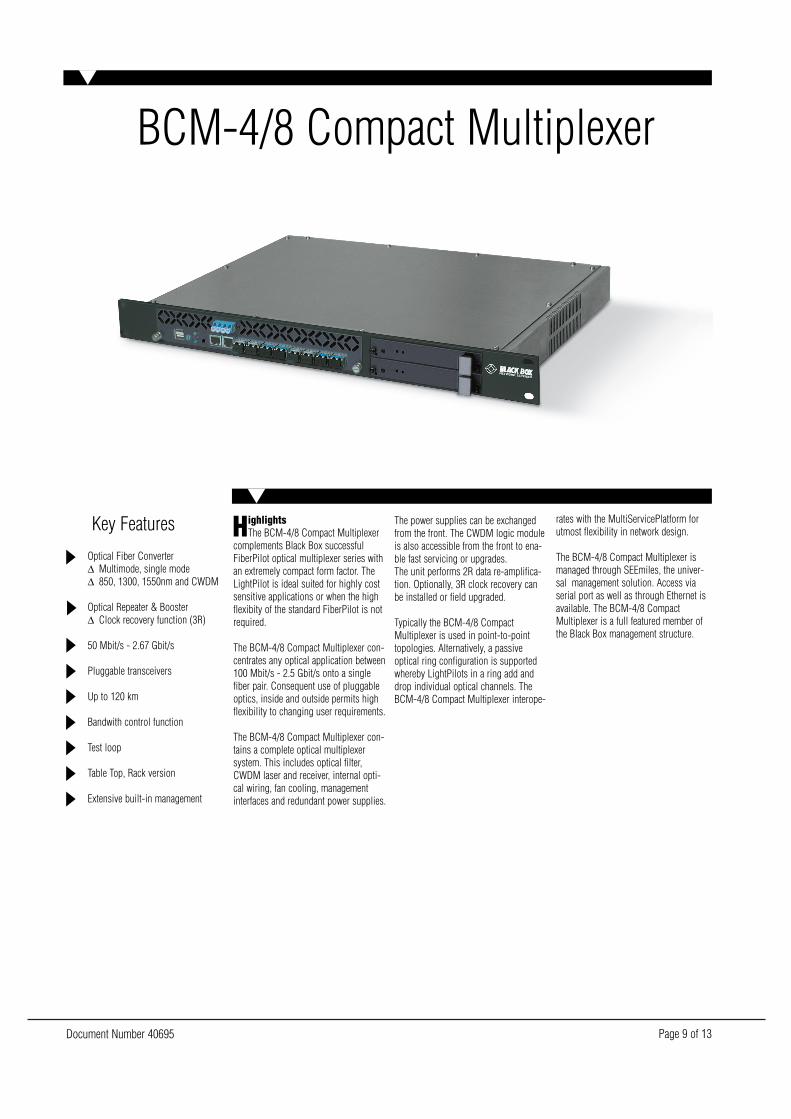
BCM-4/8 Compact Multiplexer
Key Features
Optical Fiber Converter∆ Multimode, single mode∆ 850, 1300, 1550nm and CWDM
Optical Repeater & Booster∆ Clock recovery function (3R)
50 Mbit/s - 2.67 Gbit/s
Pluggable transceivers
Up to 120 km
Bandwith control function
Test loop
Table Top, Rack version
Extensive built-in management
HighlightsThe BCM-4/8 Compact Multiplexer
complements Black Box successfulFiberPilot optical multiplexer series withan extremely compact form factor. TheLightPilot is ideal suited for highly costsensitive applications or when the highflexibity of the standard FiberPilot is notrequired.
The BCM-4/8 Compact Multiplexer con-centrates any optical application between100 Mbit/s - 2.5 Gbit/s onto a singlefiber pair. Consequent use of pluggableoptics, inside and outside permits highflexibility to changing user requirements.
The BCM-4/8 Compact Multiplexer con-tains a complete optical multiplexersystem. This includes optical filter,CWDM laser and receiver, internal opti-cal wiring, fan cooling, managementinterfaces and redundant power supplies.
The power supplies can be exchangedfrom the front. The CWDM logic moduleis also accessible from the front to ena-ble fast servicing or upgrades.The unit performs 2R data re-amplifica-tion. Optionally, 3R clock recovery canbe installed or field upgraded.
Typically the BCM-4/8 CompactMultiplexer is used in point-to-pointtopologies. Alternatively, a passiveoptical ring configuration is supportedwhereby LightPilots in a ring add anddrop individual optical channels. TheBCM-4/8 Compact Multiplexer interope-
rates with the MultiServicePlatform forutmost flexibility in network design.
The BCM-4/8 Compact Multiplexer ismanaged through SEEmiles, the univer-sal management solution. Access viaserial port as well as through Ethernet isavailable. The BCM-4/8 CompactMultiplexer is a full featured member ofthe Black Box management structure.
Document Number 40695 Page 10 of 13
Optical Interface user sideSFP (Small form Factor Pluggable)(for detailed optical data please refer toSFP technical Information)
SFP MM/LC/1300/266Multimode, 1300 nm, 50 – 266 Mbit/s,LC connector;
SFP MM/LC/1300/622Multimode, 1300 nm, 50 - 700 Mbit/s,LC connector
SFP SM/LC/1300/266/SSinglemode, 1300 nm, 50 – 266 Mbit/s,LC connector, (typ. 15 km)*
SFP SM/LC/1300/622/SSingle Mode, 1300 nm, 50 – 700Mbit/s, LC connector, (typ. 2 km)*
SFP MM/LC/850/1250Multimode, 850 nm (VCSEL), 1000 –1250 Mbit/s, LC connector
SFP SM/LC/1300/1250/SSingle Mode, 1300 nm, 1000 – 1250Mbit/s, LC connector, (typ. 10 km)*
SFP MM/LC/850/2125Multimode, 850 nm, 1000 – 2125Mbit/s, LC connector
SFP SM/LC/1300/2500/SSingle Mode, 1300 nm, 155 – 2670Mbit/s, LC connector, (typ. 10 km, 2kmOC-48)*
Optical CWDM Interfaces Inside(premium version)SFP (Small Form Factor Pouggable)
SFP SM/LC/C1xxx/1250/VSingle Mode, CWDM: 1470, 1490,1510, 1530, 1550, 1570, 1610nm, 50 -1300 Mbit/s, LC connector, (typ. 50 kmwith filter loss)*; Tx ower -3dBm min/ +2dBm max, Rx Sensibility -23dBm/Saturation -3dB
SFP SM/LC/C1xxx/2500/VSingle Mode, CWDM: 1470, 1490, 1510,1530, 1550, 1570, 1610 nm, 125 – 2670Mbit/s, LC connector, (typ. 50 km wit fil-ter loss)*, Tx Power +0 dBm min/ +5dBm max, Rx Sensitivity -21 dBm/Saturation +0 dB
SFP SM/LC/C1xxx/2500/USingle Mode, CWDM: 1470, 1490, 1510,1530, 1550, 1570, 1610 nm, 125 – 2670Mbit/s, LC connector, (typ. 70 km wit fil-ter loss)*, Tx Power +0 dBm min/ +5dBm max, Rx Sensitivity -28 dBm/Saturation -7 dB
SpecificationsData Rates50 Mbit/s - 2.5 Gbit/s (for 2.488 Gbit/s3R function recommended)
Typical ProtocolsSDH, SONET, ATM, Gigabit Ethernet,Fast Ethernet, Fibre Channel, FICON
Typical ApplicationsCarrier Access, LAN Extension, SAN,Broadcasting, Data Save
Diagnostic FunctionsSignal Detect of every port, temperatureand operating voltage status, Opticalpower levels (dending on optics used),Traps and statistics, Connection toNetwork Management System (SerialRS232 or Ethernet)
BCM-4/8 Versions- 4 channel standard veersion with
built-in optics (up to 1,25 Gbit/s- 4 channel premium version witch
pluggable CWDM SFP optics inside- 8 channel standard version with
built-in optics (up to 1,25 Gbit/s)- 8 channel premium version with
pluggable CWDM SFP optics inside- Add/drop version witch add/drop
optics, consult dealer for details
Power Supply RackSlide-in supplyInput — 115 - 240 V AC, 50/60 Hz,Power Factor CorrectionFuse — EU: 250 V/1 A (slow)Output — 5 V / 10 A (50 W)
Dimensions (H x W x D)Complete Rack —45 x 482 x 305 mm (1 HU),Designed to be mounted in 19” cabinet.
Safety and relevant StandardsCE conform, FCC part 15, DOC, CDRH21 CFR 1040, Laser Class I Product,UL (listing pending)
Ordering informationITEM CODECompact Multiplexer (SFPs not incl.), up to 2.67 Gbpx LC, 1 xLink Singlemode LC, 1 HU 19”BCM-4, 4-Ports . . . . . . . . . . . . . . . . . . . . . . . . . . . . . . . . . . .LHS824AEBCM-8, 8-Ports . . . . . . . . . . . . . . . . . . . . . . . . . . . . . . . . . . .LHS828AE
Document Number 40695 Page 11 of 13
Fiber-Loader
Key Features
1 channel CWDM over single fiber
Versions:∆ Gigabit Ethernet, 1 G Fibre
Channel, 2 G Fibre Channel∆ SDH and ATM (up to 2.488
Mbit/s)
Highly space saving
Compatible to FiberPilot platform
Pluggable lasers (SFP)
Up to 50 km
Clock Recovery (3R)
Extensive management
Real „Plug-and-Play“ solution
HighlightsThe Fiber-Loader (Multiplexing
Solution) is the ideal and cost effectiveway to save fiber costs. Due to the use ofCWDM technology a fiber can be used inmultiple ways. With different wave-lengths data can betransmitted in parallel over a single fiberallowing the secondary fiber of a fiberpair to also be used for data transmis-sion.
The various versions of the Fiber-Loadersupport a wide range of applications andservices such as Gigabit Ethernet, SAN(Fibre Channel), ATM and SDH. A bidi-rectional application is transported overone single fiber up to 50km by usingwavelength division multiplexing.
The BFL-2 devices of the Fiber-Loadersupport Network Management functiona-lity and can be configured and monitoredwith a PC via the free Black Box GUI b1View.The use of pluggable lasers (SFP) ena-bles flexible configuration of the devices.This flexibility supports bandwidth andapplication upgrades and the use toget-her with further Black Box components.
It was never that easy to use CWDMtechnology. The devices are deliveredpreconfigured and ready for installation.An easy Getting Started Guide supportsthe installation.Optional NMS software b1 View can beinstalled on a PC to monitor, configureand use extensive test functions of thedevices via a comfortable graphical userinterface.
BFL-1
SFP MM/LC/850/2125Multimode, 850 nm, 1000 - 2125 Mbit/s,LC connector,Tx Power -9dBm min/ -4dBm maxRx Sensitivity -15 dBm
SFP MM/LC/1300/2500/SSinglemode, 1300 nm, 155 – 2500Mbit/s, LC connector;
SFP SM/LC/1300/2500/SMultimode, 1300 nm, 50 - 700 Mbit/s, LCconnector (typ. 10 km, 2 km at STM-16)Tx Power -9dBm min/ -3dBm maxRx Sensitivity -18dBm/ Saturation -3dB
Version Fibe ChannelTransmission over single mode fiber, SCconnector, Optical budget (possible fiberattenuation): 17 dB (typ. 50 km)
Version SDH and ATMTransmission over Singlemodefiber, SCconnector, Optical budget (possible fiberattenuation): 17 dB (typ. 50 km)
Power SupplyInput — 100 - 240 V AC, 50/60 Hz, 60- 72 VAOutput — 5 V DC, 4 A
SpecificationsDimensions (H x W x D)Table Top unit — 37 x 103 x 170 mm
Safety and relevant StandardsCE conform, FCC part 15, DOC, CDRH21 CFR 1040, Laser Class I M Product
Delivery PackageModules —- 2 x WDM-1/C -A/LC/1530/1550/
-L/SC/SINGLE (filter cable)- 2 x CAB CON /RJ11/DB9F/2M (NMS
connecotr cable)- 1 x CD NMS Software SEEmiles,
installation instruction and handbooks
The Fiber-Loader (Multiplexing Solution) is the ideal and cost effective way to save fiber costs. Due to the use of CWDM technology a fiber canbe used in multiple ways.
Ordering informationITEM CODEBFL-1 Link-Packet Fiber-Loader 1, 1 x Entry850 MM up to 1,125 Gbps over 1 SM up to 50 km . . . . . . .LHS811AE-G1300 SM up to 2,67 Gbps over 1 SM up to 50 km . . . . . . . .LHS811AE-A
Document Number 40695 Page 12 of 13
Key Features
2 channel CWDM over single fiber
Versions:∆ Gigabit Ethernet, 1 G Fibre
Channel, 2 G Fibre Channel∆ SDH and ATM (up to 2.488
Mbit/s)
3 HU 19´´ rack for up to 11 xMuXolutions
Alternative table top for customerside
Compatible to FiberPilot platform
Up to 50 km to remote sides
Extensive management
Real „Plug-and-Play“ solution
HighlightsThe Fiber-Loader (Multiplexing
Solution) is the ideal and cost effectiveway to save fiber costs. Due to the use ofCWDM technology a fiber can be used inmultiple ways. With different wave-lengths data can betransmitted in parallel over a single fiberallowing the secondary fiber of afiber pair to also be used for data trans-mission.
The various versions of the Fiber-Loadersupport a wide range of applications andservices such as Gigabit Ethernet, SAN(Fibre Channel), ATM and SDH. Twobidirectional applications are transportedover one single fiber up to 50km byusing wavelength division multiplexing.The BFL-2 devices of the Fiber-Loadersupport Network Management functiona-lity and can be configured and monitoredwith a PC via the free GUI b1 View.The use of pluggable lasers (SFP) ena-bles flexible configuration of the devices.This flexibility supports bandwidth andapplication upgrades and the use toget-her with further Black Box components.It was never that easy to use CWDMtechnology. The devices are delivered
preconfigured and ready for installation.An easy Getting Started Guide supportsthe installation.Optional NMS software b1 View can beinstalled on a PC to monitor, configureand use extensive test functions of thedevices via a comfortable graphical userinterface.
BFL-2
MultiServicePlatform RackRequired for Black Box rack versions,includes Power Supply and NetworkTermination module for serial access
Power Supply Table TopInput — 100 - 240 V AC, 50/60 Hz, 60 -72 VAOutput — 5 V DC, 4 A (typ. currentbelow 2 A)
Power Supply RackSlide-in supply with integrated fanInput — 115 - 230 V AC, 50/60 Hz,Power Factor CorrectionFuse — EU: 250 / 4 A (slow)Output — 5 V, 40 A (200W)
SpecificationsDimensions (H x W x D)Table Top unit — 37 x 103 x 170 mmRack module — 129 x 25 x 190 mmComplete Rack —134 x 482 x 370 mm (3HU),Designed to be mounted in 19” cabinet
Safety and StandardsCE conform, FCC part 15, DOC, CDRH21 CFR 1040, Laser Class I M Product
Delivery PackageModules —- 2 x CFC 4-1 -A/LC/1510/1530/1550/
1570/-L/SC/SINGLE (filter cable)- 2 x CAB CON /RJ11/DB9F/2M (NMS
connecotr cable)- 1 x CD NMS Software SEEmiles,
installation instruction and handbooksAdditional modules —- 1 or 2 x MultiServicePlatform Rack
Ordering informationITEM CODEBFL-2 Link-Packet Fiber-Loader 2, 2 x Entry850 MM up to 1,125 Gbps over 1 SM up to 50 km . . . . . . .LHS812AE-G1300 SM up to 2,67 Gbps over 1 SM up to 50 km . . . . . . . .LHS812AE-A
Document Number 40695 Page 13 of 13
Black Box Network Services - The world’s largest network services companyWe are, with 25 years of experience, theworld leader in network infrastructureservices.
On the Phone — no charge, answercalls in less than 20 secounds, find theright product with our technical experts.
On-site — superior design and engi-neering, Certified installations, end-to-end service.
On-line — receive technical knowledgeon-line, including technology overviews,Black Box Explains and the KnowledgeBox.
Most comprehensive TECHNICALSUPPORT — our best Product! Freehotline TECH SUPPORT!
The world’s best customerservice — Custom design servicesand products, the best warranties,money-saving discount programs.
BLACK BOX exclusives —Certification Plus. Guaranted-for-lifeproducts and services.
Key Features
4 chanel TDM & CWDM over singlefiber
Supported applictions:∆ Fast Ethernet∆ FDDI∆ ESCON®∆ SDH and ATM (155 Mbit/s)
Highly space saving
Compatible to FiberPilot platform
Pluggable lasers (SFP)
Up to 50 km
Extensive management
Real „Plug-and-Play“ solution
HighlightsThe Fiber-Loader (Multiplexing
Solution) is the ideal and cost effectiveway to save fiber costs. Due to the com-bination of CWDM with the TDM techno-logy a fiber can be used in multipleways. With different wavelengths datacan be transmitted in parallel over a sin-gle fiber allowing the secondary fiber ofa fiber pair to also be used for datatransmission. By using the time multi-plex technology applications up to 200Mbit/s can be preconcentrated and thefiber is used most effective.
The various versions of the Fiber-Loadersupport a wide range of applications andservices such as Gigabit Ethernet, SAN(Fibre Channel), ATM and SDH. Fourapplications are transported over one
single fiber up to 50km by using timeand wavelength division multiplexing.
The BTM 4-1 devices of the Fiber-Loadersupport Network Management functiona-lity and can be configured and monitoredwith a PC via the free GUI b1 View.The use of pluggable lasers (SFP) ena-bles flexible configuration of the devices.This flexibility supports bandwidth andapplication upgrades and the use toget-her with further Black Box components.
It was never that easy to use multiplexingtechnology. The devices are deliveredpreconfigured and ready for installation.An easy Getting Started Guide supportsthe installation.Optional NMS software b1 View can beinstalled on a PC to monitor, configure
and use extensive test functions of thedevices via a comfortable graphical userinterface.
BFL-4L
TDM 4-1/T -A/MM/LC/1300/200Multimode, 1300 nm, 50-266 Mbit/s, LCconnectorTx Power -19 dBm min/ -14dBm maxRx Sensitivity -30 dBm/ Saturation -14dB
Fiber-Loader BFL-4LTransmission over Singlemode fiber, SCconnector, optical budget (possible fiberattenuation): 17 dB (typ.50 km)
Power SupplySlide-in supply with integrated fanInput — 100 - 240 V AC, 50/60 Hz, 60- 72 VAOutput — 5 V DC, 4 A
SpecificationsDimensions (H x W x D)Table Top unit — 37 x 103 x 170 mm
Safety and StandardsCE conform, FCC part 15, DOC, CDRH21 CFR 1040, Laser Class I M Product
Delivery PackageModules —- Fast Ethernet, FDDI, ATM OC-3, SDH
STM-1 and ESCON with 1300 nm Multimode Interface
- 2 x TDM 4-1 -A/Mm/LC/1300/200-L/SFP (Time Multiplexer)
- 2 x SFP SM/LC/C15xx/1250/V(pluggable transceiver for link)
- 2 x WDM-1/C -A/LC/1530/1550 -L/SC/SINGLE (Filter Cable)
- 2 x CAB CON /RJ11/DB9F/2M (NMS connecotr cable)
- 1 x CD NMS Software SEEmiles, installation instruction and handbooks
Ordering informationITEM CODEBFL-4L Link-Packet Fiber-Loader 4L, 4 x Entry1300 MM up to 200 Mbps over 1 SM up to 50 km . . . . . . . . .LHS814AE