Embed Size (px)
Citation preview
CVX-1300_MAN_112011
CVX-1300Operations Manual
DataBender™ Universal Format Converter
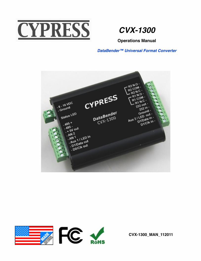
Data I/OReader - Wiegand, Strobed (Clock & Data), F/2FLED - 0 to 30vInterface
+5vDC @ 100 maOutput
95% (non-condensing)
Storage (-55°C to +150°C)Operating (-40°C to +80°C*)
Power Unreg Input 8 to 16VDC* @ 200ma MaxInput
Humidity
Aluminum enclosureSize 3.5” x 2.75” x .75”
Temp
Physical
3.3”
DataBender CVX-1300
2.8”
1.4”
3.65”
ø 0.15”
External Dimensions and Mounting Holes
Unit Height = 0.75”
Electrical and Mechanical Specifications
* See notes on following page for temperature and power ratings
This complies with part 15 of the FCC rules Operation is subject to the following two conditions: (1) This device may not cause harmful interference, and (2) this device must accept any interference received, including interference that may cause undesired operation.
Cypress Computer Systems, Inc. ⌖ Lapeer, MI 48446 ⌖ www.cypresscomputer.com© 2011 Cypress Computer Systems Inc.
Initial Setup - CVX-1300 ConverterThe CVX-1300 will support many different input and output formats.
The CVX-1300 replaces the CVX-1200 and many of the standard Cypress CVT series of converters (e.g. CVT-2232 CVT-9102).
A DIP switch determines which conversion process will be used.
A “Legacy” cross reference chart is provided to quickly determine which settings to use for standard Cypress converter numbers. In most cases several baud rate options are available to expand the capabilities of existing converters. The Legacy cross reference chart will list the converter CVT number and the CVX numbers and the DIP switch setting that will apply. Use the converter numbers to find the DIP switch settings on the CVX-1300 application charts.
Setting up the CVX-1300 converter:
1. First determine which converter (conversion process) is required for the application. This may be one of the standard Cypress converters or one of the new converters that are now part of the CVX-1300 library. All of the different conversion processes are described in detail in this manual. Each process will have a wiring diagram and specification sheet to describe the wiring connections and operation.
2. Set the DIP switch to the setting called out in the CVX application chart.
3. Refer to the wiring diagram for the particular converter that is being used. The wiring diagrams are different depending upon the type of conversion being performed.
4. Connect power to the CVX-1300 board.
5. If the diagnostic indicator LED flashes Green slowly, a valid converter number has been selected. If the diagnostic indicator is illuminated a solid Red color, an invalid DIP switch setting has been made.
6. Connect peripheral devices (Readers, Panel, Switches etc.) according to the appropriate wiring diagram.
LEGACY CONVERTER EXAMPLE: You need a CVT-2232 that operates at 2400 Baud.
The Legacy Compatibility chart calls out CVX numbers 1,2, and 3.
Looking at the CVX application charts for #1,#2,and #3 lists 3 baud rates.Selecting the 2400 Baud rate for CVX converter #2 would yield a DIP switch setting of:1 OFF, 2 ON , 3 OFF, 4 OFF, 5 OFF, 6 OFF, 7 OFF, 8 OFF
The wiring diagram would reference the Wiegand to Serial connections.
NOTE: The CVX-1300 does not use an onboard DB type connector for RS-232 serial signals.Serial connections can be made directly to the 12 position connector.An optional patch cord is available with a Female DB-9 connector and flying leads.The wiring diagrams indicate the equivalent DB-9 connections to the CVX-1300 J3 connector.
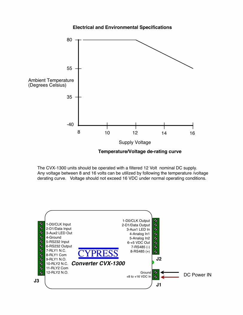
Electrical and Environmental Specifications
8 10 12 14 16
80
55
35
-40
Ambient Temperature(Degrees Celsius)
Supply Voltage
Temperature/Voltage de-rating curve
The CVX-1300 units should be operated with a filtered 12 Volt nominal DC supply. Any voltage between 8 and 16 volts can be utilized by following the temperature /voltage derating curve. Voltage should not exceed 16 VDC under normal operating conditions.
DC Power IN* Converter CVX-1300
CYPRESS
Ground+8 to +16 VDC In
1-D0/CLK Input2-D1/Data Input3-Aux2 LED Out4-Ground5-RS232 Input6-RS232 Output7-RLY1 N.C.8-RLY1 Com9-RLY1 N.O.10-RLY2 N.C.11-RLY2 Com12-RLY2 N.O.
1-D0/CLK Output2-D1/Data Output
3-Aux1 LED In4-Analog In15-Analog In2
6-+5 VDC Out7-RS485 (-)8-RS485 (+)
J1
J2
J3
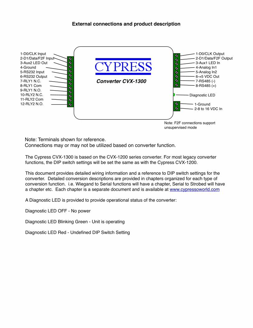
The Cypress CVX-1300 is based on the CVX-1200 series converter. For most legacy converter functions, the DIP switch settings will be set the same as with the Cypress CVX-1200.
This document provides detailed wiring information and a reference to DIP switch settings for the converter. Detailed conversion descriptions are provided in chapters organized for each type of conversion function. i.e. Wiegand to Serial functions will have a chapter, Serial to Strobed will have a chapter etc. Each chapter is a separate document and is available at www.cypressoworld.com
A Diagnostic LED is provided to provide operational status of the converter:
Diagnostic LED OFF - No power
Diagnostic LED Blinking Green - Unit is operating
Diagnostic LED Red - Undefined DIP Switch Setting
Note: Terminals shown for reference. Connections may or may not be utilized based on converter function.
External connections and product description
Converter CVX-1300
1-D0/CLK Input2-D1/Data/F2F Input3-Aux2 LED Out4-Ground5-RS232 Input6-RS232 Output7-RLY1 N.C.8-RLY1 Com9-RLY1 N.O.10-RLY2 N.C.11-RLY2 Com12-RLY2 N.O.
1-D0/CLK Output2-D1/Data/F2F Output3-Aux1 LED In4-Analog In15-Analog In26-+5 VDC Out7-RS485 (-)8-RS485 (+)
1-Ground2-8 to 16 VDC In
Diagnostic LED
Note: F2F connections support unsupervised mode
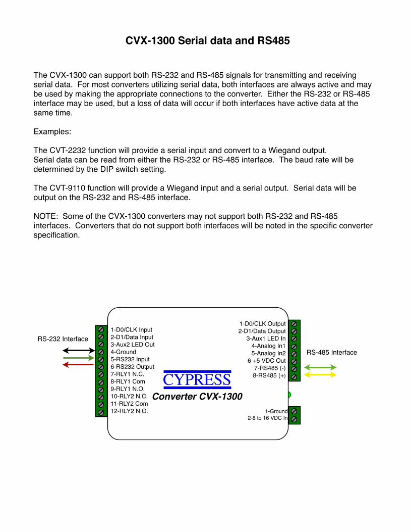
CVX-1300 Serial data and RS485
The CVX-1300 can support both RS-232 and RS-485 signals for transmitting and receiving serial data. For most converters utilizing serial data, both interfaces are always active and may be used by making the appropriate connections to the converter. Either the RS-232 or RS-485 interface may be used, but a loss of data will occur if both interfaces have active data at the same time.
Examples:
The CVT-2232 function will provide a serial input and convert to a Wiegand output.Serial data can be read from either the RS-232 or RS-485 interface. The baud rate will be determined by the DIP switch setting.
The CVT-9110 function will provide a Wiegand input and a serial output. Serial data will be output on the RS-232 and RS-485 interface.
NOTE: Some of the CVX-1300 converters may not support both RS-232 and RS-485 interfaces. Converters that do not support both interfaces will be noted in the specific converter specification.
* Converter CVX-1300 CYPRESS
1-Ground2-8 to 16 VDC In
1-D0/CLK Input2-D1/Data Input3-Aux2 LED Out4-Ground5-RS232 Input6-RS232 Output7-RLY1 N.C.8-RLY1 Com9-RLY1 N.O.10-RLY2 N.C.11-RLY2 Com12-RLY2 N.O.
1-D0/CLK Output2-D1/Data Output
3-Aux1 LED In4-Analog In15-Analog In2
6-+5 VDC Out7-RS485 (-)8-RS485 (+)
RS-232 Interface
RS-485 Interface

This Page left intentionally blank
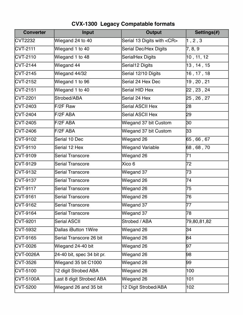
Converter Input Output Settings(#)CVT2232 Wiegand 24 to 40 Serial 13 Digits with <CR> 1 , 2 , 3CVT-2111 Wiegand 1 to 40 Serial Dec/Hex Digits 7, 8, 9CVT-2110 Wiegand 1 to 48 SerialHex Digits 10 , 11, 12CVT-2144 Wiegand 44 Serial12 Digits 13 , 14 , 15CVT-2145 Wiegand 44/32 Serial 12/10 Digits 16 , 17 , 18CVT-2152 Wiegand 1 to 96 Serial 24 Hex Dec 19 , 20 , 21CVT-2151 Wiegand 1 to 40 Serial HID Hex 22 , 23 , 24CVT-2201 Strobed/ABA Serial 24 Hex 25 , 26 , 27CVT-2403 F/2F Raw Serial ASCII Hex 28CVT-2404 F/2F ABA Serial ASCII Hex 29CVT-2405 F/2F ABA Wiegand 37 bit Custom 30CVT-2406 F/2F ABA Wiegand 37 bit Custom 33CVT-9102 Serial 10 Dec Wiegand 26 65 , 66 , 67CVT-9110 Serial 12 Hex Wiegand Variable 68 , 68 , 70CVT-9109 Serial Transcore Wiegand 26 71CVT-9129 Serial Transcore Xico 6 72CVT-9132 Serial Transcore Wiegand 37 73CVT-9137 Serial Transcore Wiegand 26 74CVT-9117 Serial Transcore Wiegand 26 75CVT-9161 Serial Transcore Wiegand 26 76CVT-9162 Serial Transcore Wiegand 37 77CVT-9164 Serial Transcore Wiegand 37 78CVT-9201 Serial ASCII Strobed / ABA 79,80,81,82CVT-5932 Dallas iButton 1Wire Wiegand 26 34CVT-9165 Serial Transcore 26 bit Wiegand 26 84CVT-0026 Wiegand 24-40 bit Wiegand 26 97CVT-0026A 24-40 bit, spec 34 bit pr. Wiegand 26 98CVT-3526 Wiegand 35 bit C1000 Wiegand 26 99CVT-5100 12 digit Strobed ABA Wiegand 26 100CVT-5100A Last 8 digit Strobed ABA Wiegand 26 101CVT-5200 Wiegand 26 and 35 bit 12 Digit Strobed/ABA 102
CVX-1300 Legacy Compatable formats
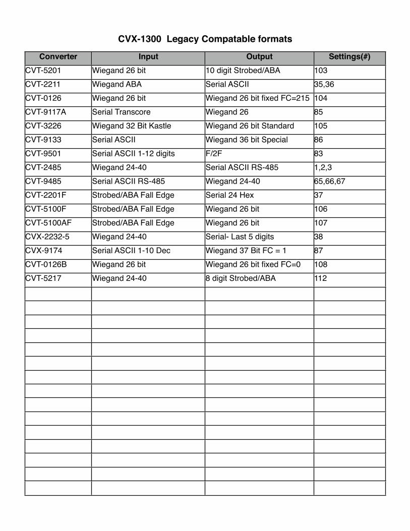
Converter Input Output Settings(#)CVT-5201 Wiegand 26 bit 10 digit Strobed/ABA 103CVT-2211 Wiegand ABA Serial ASCII 35,36CVT-0126 Wiegand 26 bit Wiegand 26 bit fixed FC=215 104CVT-9117A Serial Transcore Wiegand 26 85CVT-3226 Wiegand 32 Bit Kastle Wiegand 26 bit Standard 105CVT-9133 Serial ASCII Wiegand 36 bit Special 86CVT-9501 Serial ASCII 1-12 digits F/2F 83CVT-2485 Wiegand 24-40 Serial ASCII RS-485 1,2,3CVT-9485 Serial ASCII RS-485 Wiegand 24-40 65,66,67CVT-2201F Strobed/ABA Fall Edge Serial 24 Hex 37CVT-5100F Strobed/ABA Fall Edge Wiegand 26 bit 106CVT-5100AF Strobed/ABA Fall Edge Wiegand 26 bit 107CVX-2232-5 Wiegand 24-40 Serial- Last 5 digits 38CVX-9174 Serial ASCII 1-10 Dec Wiegand 37 Bit FC = 1 87CVT-0126B Wiegand 26 bit Wiegand 26 bit fixed FC=0 108CVT-5217 Wiegand 24-40 8 digit Strobed/ABA 112
CVX-1300 Legacy Compatable formats
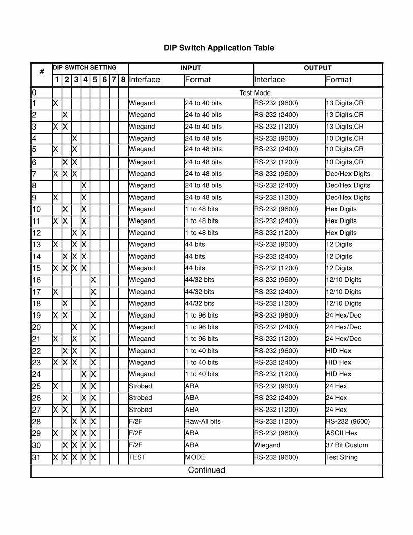
# DIP SWITCH SETTINGDIP SWITCH SETTINGDIP SWITCH SETTINGDIP SWITCH SETTINGDIP SWITCH SETTINGDIP SWITCH SETTINGDIP SWITCH SETTINGDIP SWITCH SETTING INPUTINPUT OUTPUTOUTPUT#1 2 3 4 5 6 7 8 Interface Format Interface Format
0 Test ModeTest ModeTest ModeTest Mode1 X Wiegand 24 to 40 bits RS-232 (9600) 13 Digits,CR
2 X Wiegand 24 to 40 bits RS-232 (2400) 13 Digits,CR
3 X X Wiegand 24 to 40 bits RS-232 (1200) 13 Digits,CR
4 X Wiegand 24 to 48 bits RS-232 (9600) 10 Digits,CR5 X X Wiegand 24 to 48 bits RS-232 (2400) 10 Digits,CR
6 X X Wiegand 24 to 48 bits RS-232 (1200) 10 Digits,CR
7 X X X Wiegand 24 to 48 bits RS-232 (9600) Dec/Hex Digits
8 X Wiegand 24 to 48 bits RS-232 (2400) Dec/Hex Digits
9 X X Wiegand 24 to 48 bits RS-232 (1200) Dec/Hex Digits
10 X X Wiegand 1 to 48 bits RS-232 (9600) Hex Digits
11 X X X Wiegand 1 to 48 bits RS-232 (2400) Hex Digits
12 X X Wiegand 1 to 48 bits RS-232 (1200) Hex Digits
13 X X X Wiegand 44 bits RS-232 (9600) 12 Digits
14 X X X Wiegand 44 bits RS-232 (2400) 12 Digits
15 X X X X Wiegand 44 bits RS-232 (1200) 12 Digits
16 X Wiegand 44/32 bits RS-232 (9600) 12/10 Digits
17 X X Wiegand 44/32 bits RS-232 (2400) 12/10 Digits
18 X X Wiegand 44/32 bits RS-232 (1200) 12/10 Digits
19 X X X Wiegand 1 to 96 bits RS-232 (9600) 24 Hex/Dec
20 X X Wiegand 1 to 96 bits RS-232 (2400) 24 Hex/Dec
21 X X X Wiegand 1 to 96 bits RS-232 (1200) 24 Hex/Dec
22 X X X Wiegand 1 to 40 bits RS-232 (9600) HID Hex
23 X X X X Wiegand 1 to 40 bits RS-232 (2400) HID Hex
24 X X Wiegand 1 to 40 bits RS-232 (1200) HID Hex
25 X X X Strobed ABA RS-232 (9600) 24 Hex
26 X X X Strobed ABA RS-232 (2400) 24 Hex
27 X X X X Strobed ABA RS-232 (1200) 24 Hex
28 X X X F/2F Raw-All bits RS-232 (1200) RS-232 (9600)
29 X X X X F/2F ABA RS-232 (9600) ASCII Hex
30 X X X X F/2F ABA Wiegand 37 Bit Custom
31 X X X X X TEST MODE RS-232 (9600) Test String
ContinuedContinuedContinuedContinuedContinuedContinuedContinuedContinuedContinuedContinuedContinuedContinuedContinued
DIP Switch Application Table
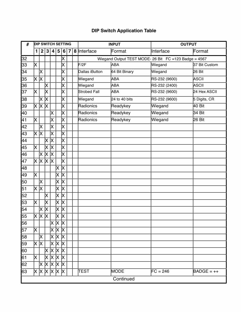
# DIP SWITCH SETTINGDIP SWITCH SETTINGDIP SWITCH SETTINGDIP SWITCH SETTINGDIP SWITCH SETTINGDIP SWITCH SETTINGDIP SWITCH SETTINGDIP SWITCH SETTING INPUTINPUT OUTPUTOUTPUT#1 2 3 4 5 6 7 8 Interface Format Interface Format
32 X Wiegand Output TEST MODE- 26 Bit FC =123 Badge = 4567Wiegand Output TEST MODE- 26 Bit FC =123 Badge = 4567Wiegand Output TEST MODE- 26 Bit FC =123 Badge = 4567Wiegand Output TEST MODE- 26 Bit FC =123 Badge = 456733 X X F/2F ABA Wiegand 37 Bit Custom
34 X X Dallas iButton 64 Bit Binary Wiegand 26 Bit
35 X X X Wiegand ABA RS-232 (9600) ASCII36 X X Wiegand ABA RS-232 (2400) ASCII37 X X X Strobed Fall ABA RS-232 (9600) 24 Hex ASCII
38 X X X Wiegand 24 to 40 bits RS-232 (9600) 5 Digits, CR
39 X X X X Radionics Readykey Wiegand 40 Bit40 X X Radionics Readykey Wiegand 34 Bit41 X X X Radionics Readykey Wiegand 26 Bit42 X X X43 X X X X44 X X X45 X X X X46 X X X X47 X X X X X48 X X49 X X X50 X X X51 X X X X52 X X X53 X X X X54 X X X X55 X X X X X56 X X X57 X X X X58 X X X X59 X X X X X60 X X X X61 X X X X X62 X X X X X63 X X X X X X TEST MODE FC = 246 BADGE = ++
ContinuedContinuedContinuedContinuedContinuedContinuedContinuedContinuedContinuedContinuedContinuedContinuedContinued
DIP Switch Application Table
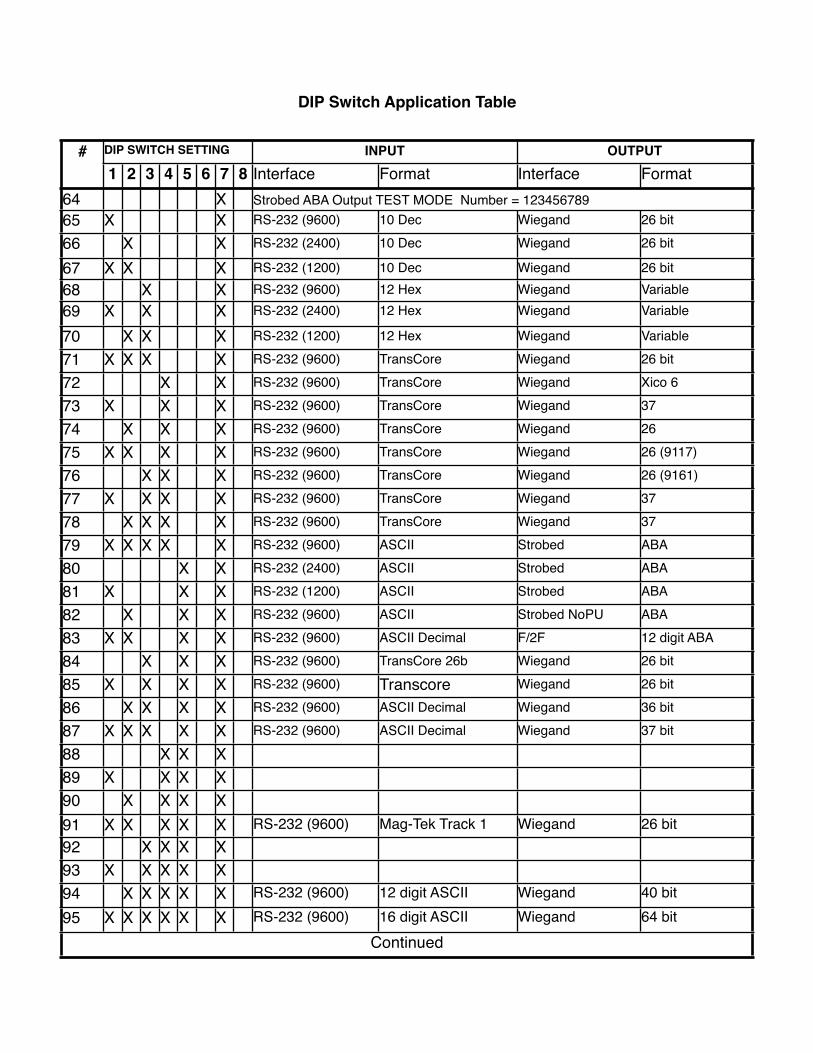
# DIP SWITCH SETTINGDIP SWITCH SETTINGDIP SWITCH SETTINGDIP SWITCH SETTINGDIP SWITCH SETTINGDIP SWITCH SETTINGDIP SWITCH SETTINGDIP SWITCH SETTING INPUTINPUT OUTPUTOUTPUT#1 2 3 4 5 6 7 8 Interface Format Interface Format
64 X Strobed ABA Output TEST MODE Number = 123456789Strobed ABA Output TEST MODE Number = 123456789Strobed ABA Output TEST MODE Number = 123456789Strobed ABA Output TEST MODE Number = 12345678965 X X RS-232 (9600) 10 Dec Wiegand 26 bit
66 X X RS-232 (2400) 10 Dec Wiegand 26 bit
67 X X X RS-232 (1200) 10 Dec Wiegand 26 bit68 X X RS-232 (9600) 12 Hex Wiegand Variable69 X X X RS-232 (2400) 12 Hex Wiegand Variable
70 X X X RS-232 (1200) 12 Hex Wiegand Variable
71 X X X X RS-232 (9600) TransCore Wiegand 26 bit
72 X X RS-232 (9600) TransCore Wiegand Xico 6
73 X X X RS-232 (9600) TransCore Wiegand 37
74 X X X RS-232 (9600) TransCore Wiegand 26
75 X X X X RS-232 (9600) TransCore Wiegand 26 (9117)
76 X X X RS-232 (9600) TransCore Wiegand 26 (9161)
77 X X X X RS-232 (9600) TransCore Wiegand 37
78 X X X X RS-232 (9600) TransCore Wiegand 37
79 X X X X X RS-232 (9600) ASCII Strobed ABA
80 X X RS-232 (2400) ASCII Strobed ABA
81 X X X RS-232 (1200) ASCII Strobed ABA
82 X X X RS-232 (9600) ASCII Strobed NoPU ABA
83 X X X X RS-232 (9600) ASCII Decimal F/2F 12 digit ABA
84 X X X RS-232 (9600) TransCore 26b Wiegand 26 bit
85 X X X X RS-232 (9600) Transcore Wiegand 26 bit
86 X X X X RS-232 (9600) ASCII Decimal Wiegand 36 bit
87 X X X X X RS-232 (9600) ASCII Decimal Wiegand 37 bit
88 X X X89 X X X X90 X X X X91 X X X X X RS-232 (9600) Mag-Tek Track 1 Wiegand 26 bit92 X X X X93 X X X X X94 X X X X X RS-232 (9600) 12 digit ASCII Wiegand 40 bit95 X X X X X X RS-232 (9600) 16 digit ASCII Wiegand 64 bit
ContinuedContinuedContinuedContinuedContinuedContinuedContinuedContinuedContinuedContinuedContinuedContinuedContinued
DIP Switch Application Table
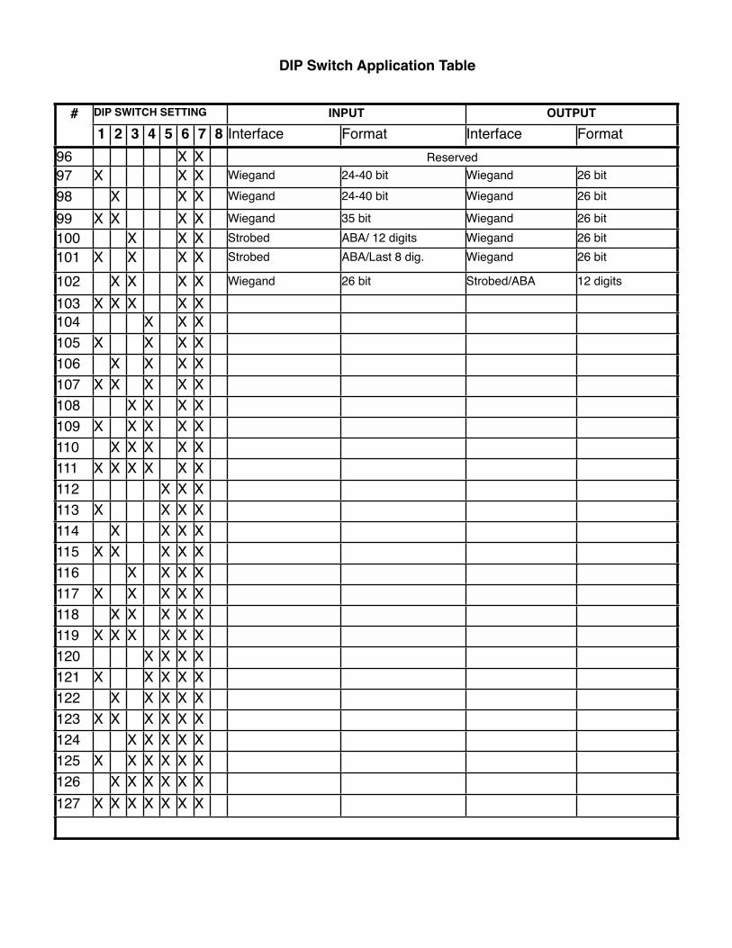
# DIP SWITCH SETTINGDIP SWITCH SETTINGDIP SWITCH SETTINGDIP SWITCH SETTINGDIP SWITCH SETTINGDIP SWITCH SETTINGDIP SWITCH SETTINGDIP SWITCH SETTING INPUTINPUT OUTPUTOUTPUT#1 2 3 4 5 6 7 8 Interface Format Interface Format
96 X X ReservedReservedReservedReserved97 X X X Wiegand 24-40 bit Wiegand 26 bit
98 X X X Wiegand 24-40 bit Wiegand 26 bit
99 X X X X Wiegand 35 bit Wiegand 26 bit100 X X X Strobed ABA/ 12 digits Wiegand 26 bit101 X X X X Strobed ABA/Last 8 dig. Wiegand 26 bit
102 X X X X Wiegand 26 bit Strobed/ABA 12 digits
103 X X X X X104 X X X105 X X X X106 X X X X107 X X X X X108 X X X X109 X X X X X110 X X X X X111 X X X X X X112 X X X113 X X X X114 X X X X115 X X X X X116 X X X X117 X X X X X118 X X X X X119 X X X X X X120 X X X X121 X X X X X122 X X X X X123 X X X X X X124 X X X X X125 X X X X X X126 X X X X X X127 X X X X X X X
DIP Switch Application Table

Standard Wiring Diagrams - CVX-1300 Converter
Wiring diagrams are referenced by function and number. The specific converter descriptions will refer to these diagrams.
CVX-1300 Electrical Connections
1. Serial data and RS485
2. Standard power supply connections
LISTING OF STANDARD WIRING DIAGRAMS
1. Wiegand to Serial.
2. Serial to Wiegand
3. Wiegand to Wiegand
4. Strobed to Serial
5. Serial to Strobed
6. Strobed to Wiegand
7. Wiegand to Strobed
8. F/2F to Wiegand
9.Serial to F2F
10. Dallas iButton to Wiegand
11. Serial to Wiegand - Special Application
12 Radionics 1 Wire to Wiegand
This device complies with part 15 of the FCC Rules.
Operation is subject to the following two conditions: (1) This device may not cause harmful interference, and (2) this device must accept any interference received, including interference that may cause undesired operation.
FCC Part 15 COMPLIANCE
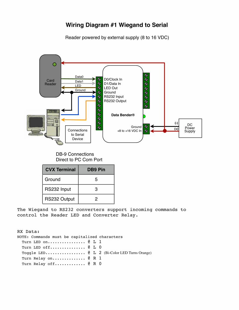
Wiring Diagram #1 Wiegand to Serial
The Wiegand to RS232 converters support incoming commands tocontrol the Reader LED and Converter Relay.
RX Data:NOTE: Commands must be capitalized characters Turn LED on................ @ L 1 Turn LED off............... @ L 0 Toggle LED................. @ L 2 (Bi-Color LED Turns Orange) Turn Relay on.............. @ R 1 Turn Relay off............. @ R 0
CVX Terminal DB9 Pin
Ground 5
RS232 Input 3
RS232 Output 2
DB-9 ConnectionsDirect to PC Com Port
Connections to Serial Device
D0/Clock InD1/Data InLED OutGroundRS232 InputRS232 Output
Ground+8 to +16 VDC In
Data Bender®
Card Reader
Data0Data1LEDGround
DCPower Supply
(-)
(+)
Reader powered by external supply (8 to 16 VDC)

Wiring Diagram #1 Wiegand to Serial
The Wiegand to RS232 converters support incoming commands tocontrol the Reader LED and Converter Relay.
RX Data:NOTE: Commands must be capitalized characters Turn LED on................ @ L 1 Turn LED off............... @ L 0 Toggle LED................. @ L 2 (Bi-Color LED Turns Orange) Turn Relay on.............. @ R 1 Turn Relay off............. @ R 0
CVX Terminal DB9 Pin
Ground 5
RS232 Input 3
RS232 Output 2
DB-9 ConnectionsDirect to PC Com Port
Reader powered by converter +5 VDC
Connections to Serial
Device
D0/Clock InD1/Data InLED OutGroundRS232 InputRS232 Output
Ground+8 to +16 VDC In
Data Bender®
Card Reader
Data0Data1LEDGround
DCPower Supply
(-)
(+)
+5VDC Out
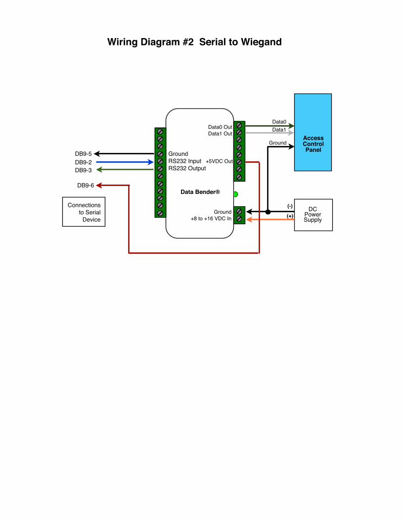
Wiring Diagram #2 Serial to Wiegand
GroundRS232 InputRS232 Output
Ground+8 to +16 VDC In
Data Bender®
Data0 OutData1 Out
Connections to Serial
Device
DB9-5DB9-2DB9-3
DB9-6
(-)
(+)DC
Power Supply
AccessControl Panel
Data0Data1
Ground
+5VDC Out
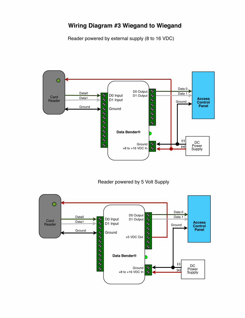
Wiring Diagram #3 Wiegand to Wiegand
Reader powered by external supply (8 to 16 VDC)
Card Reader
Data0Data1
Ground
DCPower Supply
(-)
(+)
Data 0Data 1
GroundAccessControl Panel
D0 InputD1 Input
Ground
Ground+8 to +16 VDC In
Data Bender®
D0 OutputD1 Output
Reader powered by 5 Volt Supply
Card Reader
Data0Data1
Ground
D0 InputD1 Input
Ground
Ground+8 to +16 VDC In
Data Bender®
D0 OutputD1 Output
DCPower Supply
(-)
(+)
Data 0Data 1
GroundAccessControl Panel
+5 VDC Out
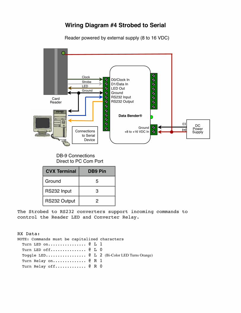
Wiring Diagram #4 Strobed to Serial
The Strobed to RS232 converters support incoming commands tocontrol the Reader LED and Converter Relay.
RX Data:NOTE: Commands must be capitalized characters Turn LED on................ @ L 1 Turn LED off............... @ L 0 Toggle LED................. @ L 2 (Bi-Color LED Turns Orange) Turn Relay on.............. @ R 1 Turn Relay off............. @ R 0
CVX Terminal DB9 Pin
Ground 5
RS232 Input 3
RS232 Output 2
DB-9 ConnectionsDirect to PC Com Port
Reader powered by external supply (8 to 16 VDC)
Connections to Serial
Device
Card Reader
D0/Clock InD1/Data InLED OutGroundRS232 InputRS232 Output
Ground+8 to +16 VDC In
Data Bender®
ClockStrobeLEDGround
DCPower Supply
(-)
(+)
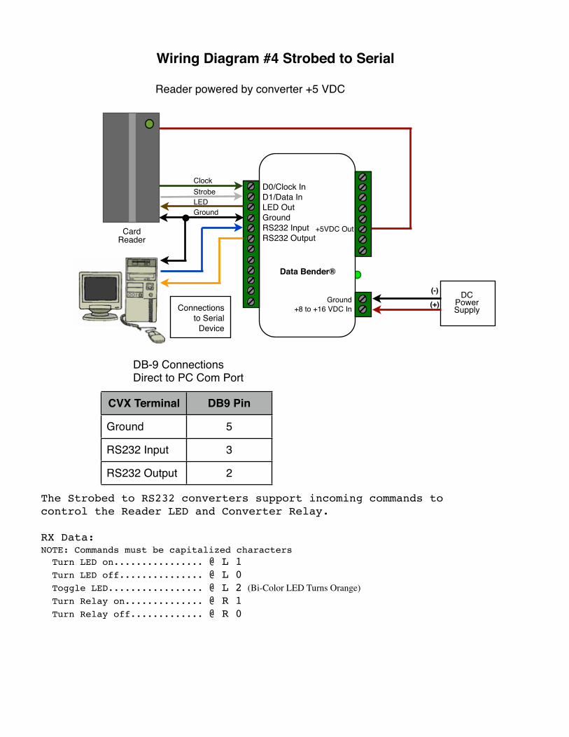
Wiring Diagram #4 Strobed to Serial
The Strobed to RS232 converters support incoming commands tocontrol the Reader LED and Converter Relay.
RX Data:NOTE: Commands must be capitalized characters Turn LED on................ @ L 1 Turn LED off............... @ L 0 Toggle LED................. @ L 2 (Bi-Color LED Turns Orange) Turn Relay on.............. @ R 1 Turn Relay off............. @ R 0
CVX Terminal DB9 Pin
Ground 5
RS232 Input 3
RS232 Output 2
DB-9 ConnectionsDirect to PC Com Port
Reader powered by converter +5 VDC
Connections to Serial
Device
Card Reader
D0/Clock InD1/Data InLED OutGroundRS232 InputRS232 Output
Ground+8 to +16 VDC In
Data Bender®
ClockStrobeLEDGround
DCPower Supply
(-)
(+)
+5VDC Out
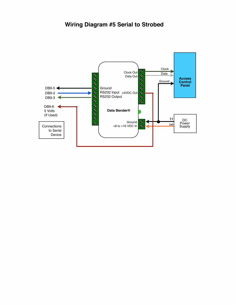
Wiring Diagram #5 Serial to Strobed
(-)
(+)DC
Power Supply
AccessControl Panel
ClockData
Ground
GroundRS232 InputRS232 Output
Ground+8 to +16 VDC In
Data Bender®
Clock OutData Out
Connections to Serial
Device
DB9-5DB9-2DB9-3
DB9-65 Volts(If Used)
+5VDC Out
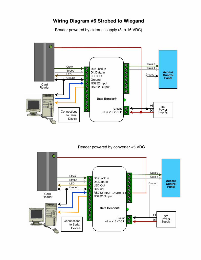
Wiring Diagram #6 Strobed to Wiegand Reader powered by external supply (8 to 16 VDC)
Reader powered by converter +5 VDC
Connections to Serial
Device
Card Reader
D0/Clock InD1/Data InLED OutGroundRS232 InputRS232 Output
Ground+8 to +16 VDC In
Data Bender®
ClockStrobeLEDGround
DCPower Supply
(-)
(+)
Data 0Data 1
GroundAccessControl Panel
Connections to Serial
Device
Card Reader
D0/Clock InD1/Data InLED OutGroundRS232 InputRS232 Output
Ground+8 to +16 VDC In
Data Bender®
ClockStrobeLEDGround
DCPower Supply
(-)
(+)
+5VDC Out
Data 0Data 1
GroundAccessControl Panel
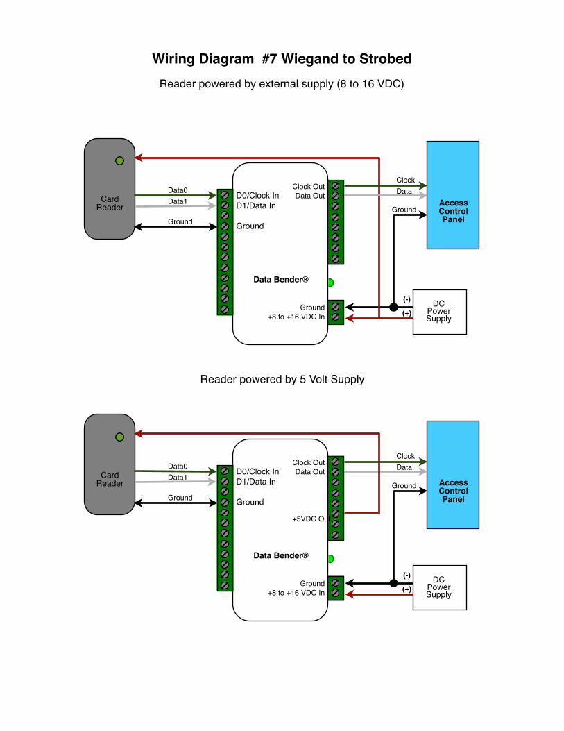
Wiring Diagram #7 Wiegand to Strobed Reader powered by external supply (8 to 16 VDC)
Card Reader
Data0Data1
Ground
DCPower Supply
(-)
(+)
ClockData
GroundAccessControl Panel
D0/Clock InD1/Data In
Ground
Ground+8 to +16 VDC In
Data Bender®
Clock OutData Out
Reader powered by 5 Volt Supply
AccessControl Panel
DCPower Supply
(-)
(+)
ClockData
Ground
D0/Clock InD1/Data In
Ground
Ground+8 to +16 VDC In
Data Bender®
Clock OutData OutCard
Reader
Data0Data1
Ground
+5VDC Out
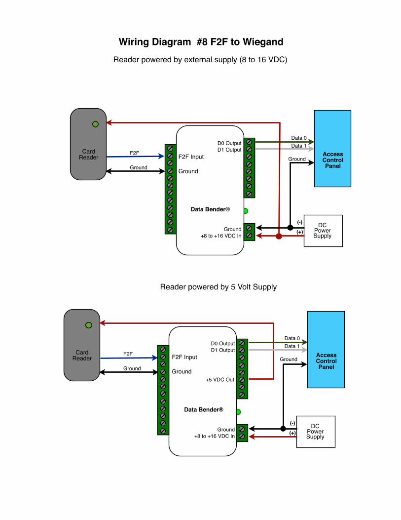
Wiring Diagram #8 F2F to WiegandReader powered by external supply (8 to 16 VDC)
F2F
Ground
Data 0Data 1
GroundCard
Reader
DCPower Supply
(-)
(+)
AccessControl Panel
F2F Input
Ground
Ground+8 to +16 VDC In
Data Bender®
D0 OutputD1 Output
Reader powered by 5 Volt Supply
Card Reader
DCPower Supply
(-)
(+)
Data 0Data 1
GroundAccessControl Panel
F2F
Ground
F2F Input
Ground
Ground+8 to +16 VDC In
Data Bender®
D0 OutputD1 Output
+5 VDC Out
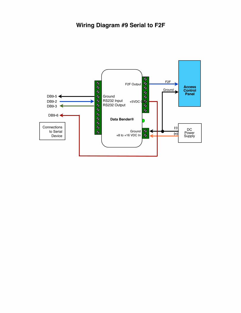
Wiring Diagram #9 Serial to F2F
GroundRS232 InputRS232 Output
Ground+8 to +16 VDC In
Data Bender®
F2F Output
Connections to Serial
Device
DB9-5DB9-2DB9-3
DB9-6
(-)
(+)DC
Power Supply
AccessControl Panel
F2F
Ground
+5VDC Out
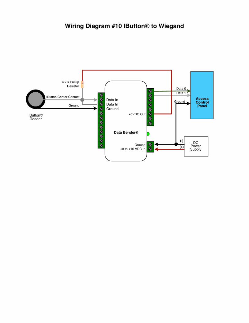
Wiring Diagram #10 IButton® to Wiegand
Data 1Data 0
Ground
DCPower Supply
(-)
(+)
AccessControl Panel
IButton Center Contact
Ground
IButton® Reader
4.7 k PullupResistor
Data InData InGround
Ground+8 to +16 VDC In
Data Bender®
+5VDC Out
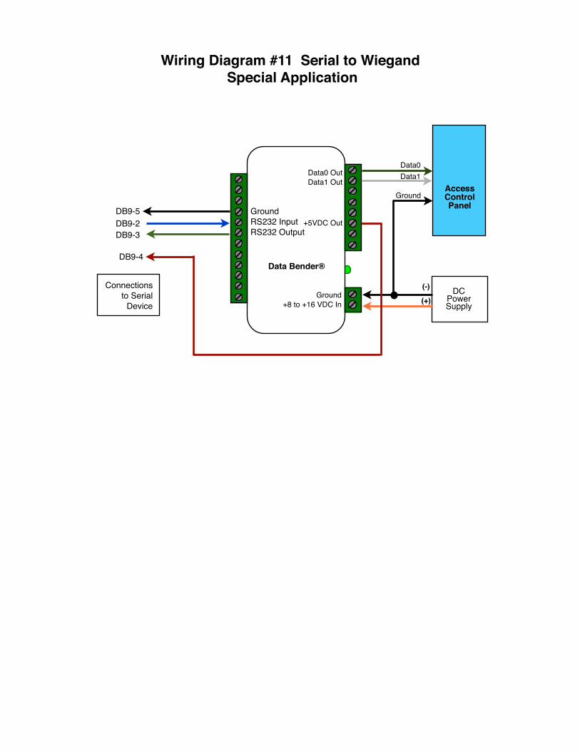
Wiring Diagram #11 Serial to Wiegand Special Application
GroundRS232 InputRS232 Output
Ground+8 to +16 VDC In
Data Bender®
Data0 OutData1 Out
Connections to Serial
Device
DB9-5DB9-2DB9-3
DB9-4
(-)
(+)DC
Power Supply
AccessControl Panel
Data0Data1
Ground
+5VDC Out
Data 0Data 1
Ground
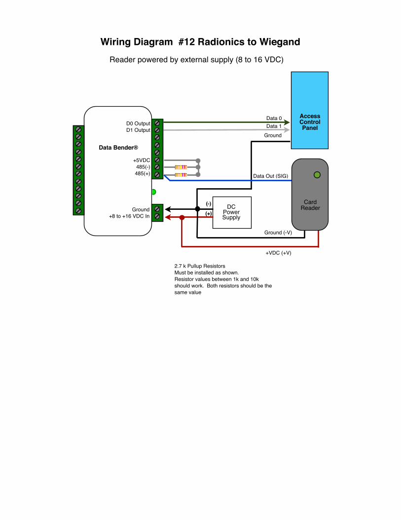
Wiring Diagram #12 Radionics to WiegandReader powered by external supply (8 to 16 VDC)
2.7 k Pullup ResistorsMust be installed as shown.Resistor values between 1k and 10k should work. Both resistors should be the same value
Data Out (SIG)
DCPower Supply
(-)
(+)
AccessControl Panel
Card Reader
+VDC (+V)
Ground (-V)
Ground+8 to +16 VDC In
Data Bender®
D0 OutputD1 Output
+5VDC485(-)485(+)


![M1675 e 112011[1]](https://img.pdfslide.us/doc/110x75/555921f7d8b42a88038b521f/m1675-e-1120111.jpg)