Embed Size (px)
Citation preview

1
Product Manual
CVS Type 67AFR Filter Regulator
Introduction
This CVS Controls product manual includes instructions for the installation, adjustment, maintenance and parts ordering of the CVS Type 67AFR Filter Regulator.
All CVS Controls equipment should be installed, operated and maintained by qualified personnel. If you have any questions regarding this equipment, contact your CVS Controls representative.
Ensure that the label of the control spring range is updated to reflect any changes in field equipment, materials, service conditions or pressure settings.
If any venting occurs or a leak develops in the pressure system this indicates that service is required. Failure to remove the regulator from service for immediate maintenance may cause a hazardous situation.
These regulators are often shipped installed on other equipment. Information on that equipment will be contained in separate manuals.
Description The CVS Type 67AFR Filter Regulator is a self-operated unit which provides continuous reduced pressures in a variety of applications and service conditions. Common use is as supply pressure regulators for pneumatic instruments.
A cellulose filter is used with the CVS Type 67AFR Filter Regulator and will remove particles greater than 0.0016 inch (0.040 mm) in diameter.
In addition, these regulators contain integral low-capacity relief valves. In this type of construction the valve stem
Figure 1: CVS Type 67AFR Regulator sits against an orifice in the diaphragm assembly. When downstream pressure increases above the set point, the diaphragm assembly moves off the valve stem and excess pressure is vented through a port hole tapped in the spring case.
Installation
Warning
Do not install any pressure equipment where service conditions exceed the manufacturer’s specifications. Over pressuring of regulator may result in leakage, equipment damage or injury. Excessive pressure can cause the pressure-containing parts to burst, or accumulated gas to explode. The CVS Type 67AFR Filter Regulator cannot be used with hazardous gas unless vented to a safe area.
CVS Controls Ltd Product Manual: CVS Type 67AFR Filter Regulator
2
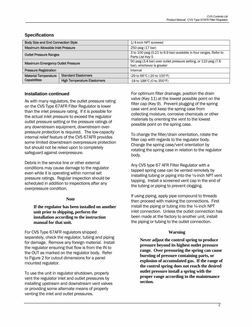
SpecificationsBody Size and End Connection Style 1/4-inch NPT screwed Maximum Allowable Inlet Pressure 250 psig (17 bar)
Outlet Pressure Ranges 3 to 100 psig (0.21 to 6.9 bar) available in four ranges. Refer to Parts List Key 5
Maximum Emergency Outlet Pressure 50 psig (3.4 bar) over outlet pressure setting, or 110 psig (7.6 bar), whichever is greater
Pressure Registration Internal Standard Elastomers -29 to 66 C (-20 to 150 F) Material Temperature
Capabilities High Temperature Elastomers -18 to 188 C (0 to 350 F)
Installation continued As with many regulators, the outlet pressure rating on the CVS Type 67AFR Filter Regulator is lower than the inlet pressure rating. If it is possible for the actual inlet pressure to exceed the regulator outlet pressure setting or the pressure ratings of any downstream equipment, downstream over-pressure protection is required. The low-capacity internal relief feature of the CVS 67AFR provides some limited downstream overpressure protection but should not be relied upon to completely safeguard against overpressure.
Debris in the service line or other external conditions may cause damage to the regulator even while it is operating within normal set pressure ratings. Regular inspection should be scheduled in addition to inspections after any overpressure condition.
Note
If the regulator has been installed on another unit prior to shipping, perform the installation according to the instruction manual for that unit.
For CVS Type 67AFR regulators shipped separately, check the regulator, tubing and piping for damage. Remove any foreign material. Install the regulator ensuring that flow is from the IN to the OUT as marked on the regulator body. Refer to Figure 2 for cutout dimensions for a panel mounted regulator.
To use the unit in regulator shutdown, properly vent the regulator inlet and outlet pressures by installing upstream and downstream vent valves or providing some alternate means of properly venting the inlet and outlet pressures.
For optimum filter drainage, position the drain valve (Key 11) at the lowest possible point on the filter cap (Key 9). Prevent plugging of the spring case vent and keep the spring case from collecting moisture, corrosive chemicals or other materials by orienting the vent to the lowest possible point on the spring case.
To change the filter/drain orientation, rotate the filter cap with regards to the regulator body. Change the spring case/vent orientation by rotating the spring case in relation to the regulator body.
Any CVS type 67 AFR Filter Regulator with a tapped spring case can be vented remotely by installing tubing or piping into the ¼-inch NPT vent tapping. Install a screened vent cap in the end of the tubing or piping to prevent clogging.
If using piping, apply pipe compound to threads then proceed with making the connections. First install the piping or tubing into the ¼-inch NPT inlet connection. Unless the outlet connection has been made at the factory to another unit, install the piping or tubing to the outlet connection.
Warning
Never adjust the control spring to produce pressure beyond its highest outlet pressure range. Over pressuring the spring can cause bursting of pressure containing parts, or explosion of accumulated gas. If the range of the control spring does not reach the desired outlet pressure install a spring with the proper range according to the maintenance section.
CVS Controls Ltd Product Manual: CVS Type 67AFR Filter Regulator
3
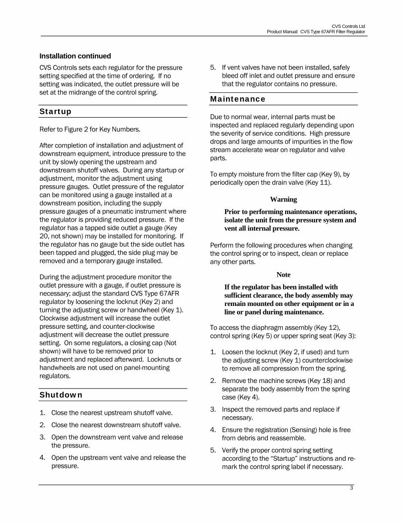
Installation continued CVS Controls sets each regulator for the pressure setting specified at the time of ordering. If no setting was indicated, the outlet pressure will be set at the midrange of the control spring.
Startup
Refer to Figure 2 for Key Numbers.
After completion of installation and adjustment of downstream equipment, introduce pressure to the unit by slowly opening the upstream and downstream shutoff valves. During any startup or adjustment, monitor the adjustment using pressure gauges. Outlet pressure of the regulator can be monitored using a gauge installed at a downstream position, including the supply pressure gauges of a pneumatic instrument where the regulator is providing reduced pressure. If the regulator has a tapped side outlet a gauge (Key 20, not shown) may be installed for monitoring. If the regulator has no gauge but the side outlet has been tapped and plugged, the side plug may be removed and a temporary gauge installed.
During the adjustment procedure monitor the outlet pressure with a gauge, if outlet pressure is necessary; adjust the standard CVS Type 67AFR regulator by loosening the locknut (Key 2) and turning the adjusting screw or handwheel (Key 1). Clockwise adjustment will increase the outlet pressure setting, and counter-clockwise adjustment will decrease the outlet pressure setting. On some regulators, a closing cap (Not shown) will have to be removed prior to adjustment and replaced afterward. Locknuts or handwheels are not used on panel-mounting regulators.
Shutdown
1. Close the nearest upstream shutoff valve.
2. Close the nearest downstream shutoff valve.
3. Open the downstream vent valve and release the pressure.
4. Open the upstream vent valve and release the pressure.
5. If vent valves have not been installed, safely bleed off inlet and outlet pressure and ensure that the regulator contains no pressure.
Maintenance
Due to normal wear, internal parts must be inspected and replaced regularly depending upon the severity of service conditions. High pressure drops and large amounts of impurities in the flow stream accelerate wear on regulator and valve parts.
To empty moisture from the filter cap (Key 9), by periodically open the drain valve (Key 11).
Warning
Prior to performing maintenance operations, isolate the unit from the pressure system and vent all internal pressure.
Perform the following procedures when changing the control spring or to inspect, clean or replace any other parts.
Note
If the regulator has been installed with sufficient clearance, the body assembly may remain mounted on other equipment or in a line or panel during maintenance.
To access the diaphragm assembly (Key 12), control spring (Key 5) or upper spring seat (Key 3):
1. Loosen the locknut (Key 2, if used) and turn the adjusting screw (Key 1) counterclockwise to remove all compression from the spring.
2. Remove the machine screws (Key 18) and separate the body assembly from the spring case (Key 4).
3. Inspect the removed parts and replace if necessary.
4. Ensure the registration (Sensing) hole is free from debris and reassemble.
5. Verify the proper control spring setting according to the “Startup” instructions and re-mark the control spring label if necessary.
CVS Controls Ltd Product Manual: CVS Type 67AFR Filter Regulator
4
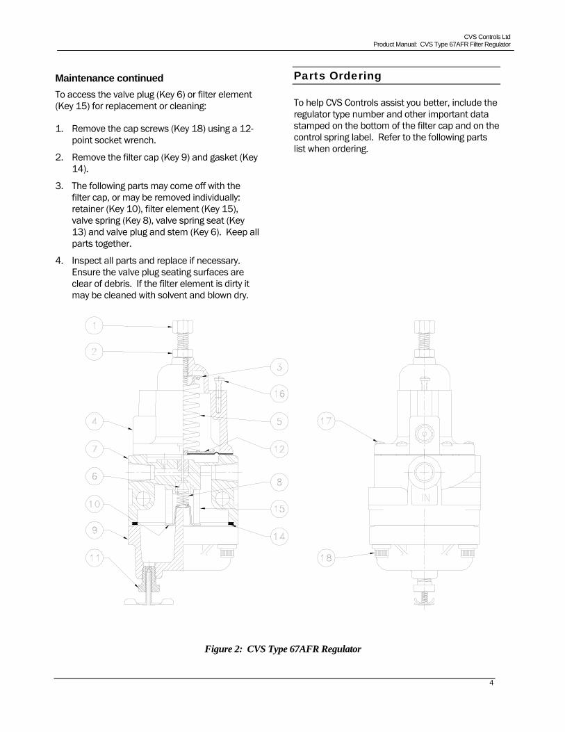
Maintenance continued To access the valve plug (Key 6) or filter element (Key 15) for replacement or cleaning:
1. Remove the cap screws (Key 18) using a 12-point socket wrench.
2. Remove the filter cap (Key 9) and gasket (Key 14).
3. The following parts may come off with the filter cap, or may be removed individually: retainer (Key 10), filter element (Key 15), valve spring (Key 8), valve spring seat (Key 13) and valve plug and stem (Key 6). Keep all parts together.
4. Inspect all parts and replace if necessary. Ensure the valve plug seating surfaces are clear of debris. If the filter element is dirty it may be cleaned with solvent and blown dry.
Parts Ordering
To help CVS Controls assist you better, include the regulator type number and other important data stamped on the bottom of the filter cap and on the control spring label. Refer to the following parts list when ordering.
Figure 2: CVS Type 67AFR Regulator
CVS Controls Ltd Product Manual: CVS Type 67AFR Filter Regulator
5
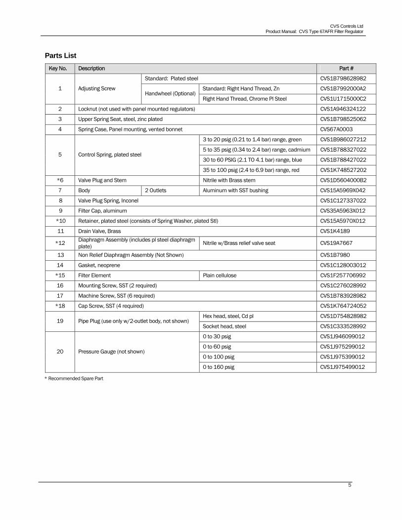
Parts List Key No. Description Part #
Standard: Plated steel CVS1B798628982
Standard: Right Hand Thread, Zn CVS1B7992000A2 1 Adjusting Screw Handwheel (Optional)
Right Hand Thread, Chrome Pl Steel CVS1U1715000C2
2 Locknut (not used with panel mounted regulators) CVS1A946324122
3 Upper Spring Seat, steel, zinc plated CVS1B798525062
4 Spring Case, Panel mounting, vented bonnet CVS67A0003
3 to 20 psig (0.21 to 1.4 bar) range, green CVS1B986027212
5 to 35 psig (0.34 to 2.4 bar) range, cadmium CVS1B788327022
30 to 60 PSIG (2.1 TO 4.1 bar) range, blue CVS1B788427022 5 Control Spring, plated steel
35 to 100 psig (2.4 to 6.9 bar) range, red CVS1K748527202
*6 Valve Plug and Stem Nitrile with Brass stem CVS1D5604000B2
7 Body 2 Outlets Aluminum with SST bushing CVS15A5969X042
8 Valve Plug Spring, Inconel CVS1C127337022
9 Filter Cap, aluminum CVS35A5963X012
*10 Retainer, plated steel (consists of Spring Washer, plated Stl) CVS15A5970X012
11 Drain Valve, Brass CVS1K4189
*12 Diaphragm Assembly (includes pl steel diaphragm plate) Nitrile w/Brass relief valve seat CVS19A7667
13 Non Relief Diaphragm Assembly (Not Shown) CVS1B7980
14 Gasket, neoprene CVS1C128003012
*15 Filter Element Plain cellulose CVS1F257706992
16 Mounting Screw, SST (2 required) CVS1C276028992
17 Machine Screw, SST (6 required) CVS1B783928982
*18 Cap Screw, SST (4 required) CVS1K764724052
Hex head, steel, Cd pl CVS1D754828982 19 Pipe Plug (use only w/2-outlet body, not shown)
Socket head, steel CVS1C333528992
0 to 30 psig CVS1J946099012
0 to 60 psig CVS1J975299012
0 to 100 psig CVS1J975399012 20 Pressure Gauge (not shown)
0 to 160 psig CVS1J975499012
* Recommended Spare Part

CVS Controls Ltd Product Manual: CVS Type 67AFR Filter Regulator
Notes

CVS Controls Ltd Product Manual: CVS Type 67AFR Filter Regulator
Notes
CVS Controls Ltd Product Manual: CVS Type 67AFR Filter Regulator
Head Office 3900 – 101 Street Edmonton, Alberta, Canada T6E 0A5 Office: (780) 437-3055 Fax: (780) 436-5461
Website: www.cvs-controls.com E-Mail: [email protected] Printed in Canada Rev 0, 09/06
Calgary Sales Office 205, 2323 – 32 Avenue NE
Calgary, Alberta, Canada T2E 6Z3 Office: (403) 250-1416
Fax: (403) 291-9487
1
Head Office 3900 – 101 Street Edmonton, Alberta, Canada T6E 0A5 Office: (780) 437-3055 Fax: (780) 436-5461
Website: www.cvs-controls.com E-Mail: [email protected]
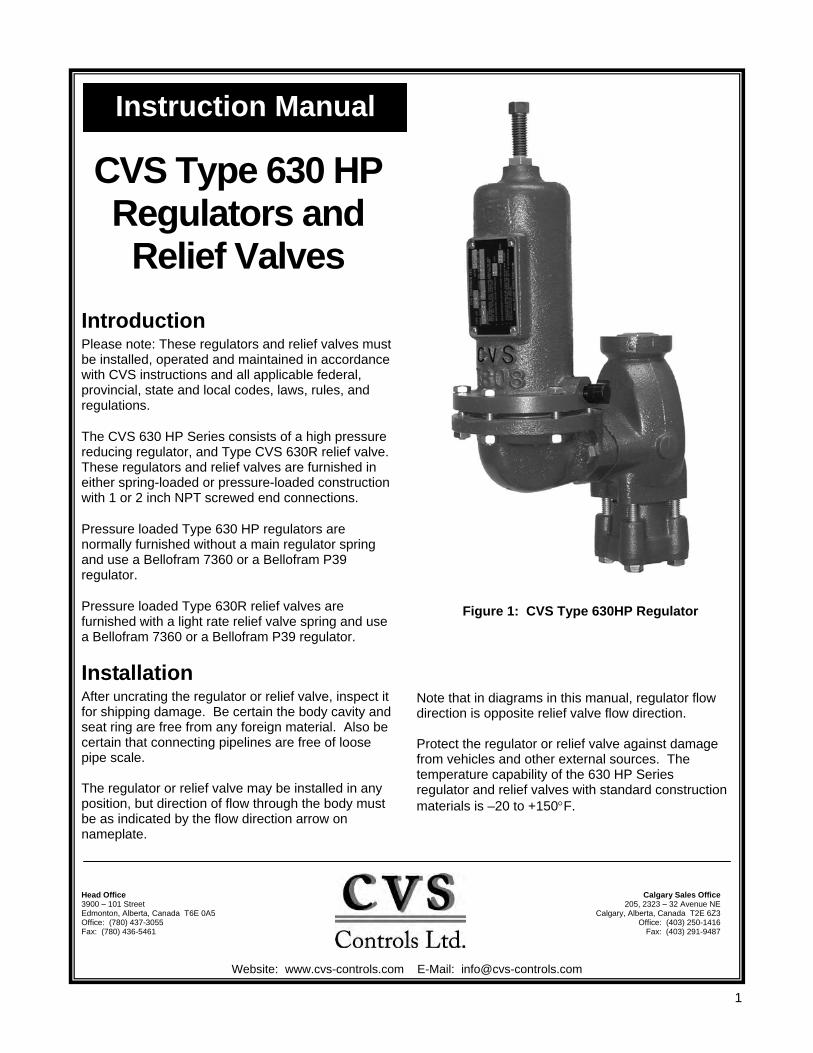
CVS Type 630 HP Regulators and Relief Valves
Introduction Please note: These regulators and relief valves must be installed, operated and maintained in accordance with CVS instructions and all applicable federal, provincial, state and local codes, laws, rules, and regulations.
The CVS 630 HP Series consists of a high pressure reducing regulator, and Type CVS 630R relief valve. These regulators and relief valves are furnished in either spring-loaded or pressure-loaded construction with 1 or 2 inch NPT screwed end connections.
Pressure loaded Type 630 HP regulators are normally furnished without a main regulator spring and use a Bellofram 7360 or a Bellofram P39 regulator.
Pressure loaded Type 630R relief valves are furnished with a light rate relief valve spring and use a Bellofram 7360 or a Bellofram P39 regulator.
Installation After uncrating the regulator or relief valve, inspect it for shipping damage. Be certain the body cavity and seat ring are free from any foreign material. Also be certain that connecting pipelines are free of loose pipe scale. The regulator or relief valve may be installed in any position, but direction of flow through the body must be as indicated by the flow direction arrow on nameplate.
Instruction Manual
Figure 1: CVS Type 630HP Regulator
Calgary Sales Office205, 2323 – 32 Avenue NE
Calgary, Alberta, Canada T2E 6Z3 Office: (403) 250-1416
Fax: (403) 291-9487
Note that in diagrams in this manual, regulator flow direction is opposite relief valve flow direction. Protect the regulator or relief valve against damage from vehicles and other external sources. The temperature capability of the 630 HP Series regulator and relief valves with standard construction materials is –20 to +150°F.
2
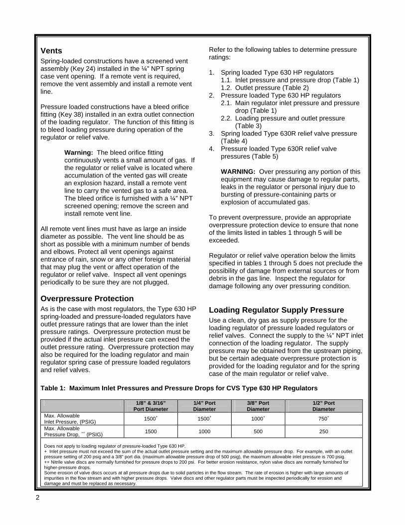
Vents Spring-loaded constructions have a screened vent assembly (Key 24) installed in the ¼” NPT spring case vent opening. If a remote vent is required, remove the vent assembly and install a remote vent line. Pressure loaded constructions have a bleed orifice fitting (Key 38) installed in an extra outlet connection of the loading regulator. The function of this fitting is to bleed loading pressure during operation of the regulator or relief valve.
Warning: The bleed orifice fitting continuously vents a small amount of gas. If the regulator or relief valve is located where accumulation of the vented gas will create an explosion hazard, install a remote vent line to carry the vented gas to a safe area. The bleed orifice is furnished with a ¼” NPT screened opening; remove the screen and install remote vent line.
All remote vent lines must have as large an inside diameter as possible. The vent line should be as short as possible with a minimum number of bends and elbows. Protect all vent openings against entrance of rain, snow or any other foreign material that may plug the vent or affect operation of the regulator or relief valve. Inspect all vent openings periodically to be sure they are not plugged.
Overpressure Protection As is the case with most regulators, the Type 630 HP spring-loaded and pressure-loaded regulators have outlet pressure ratings that are lower than the inlet pressure ratings. Overpressure protection must be provided if the actual inlet pressure can exceed the outlet pressure rating. Overpressure protection may also be required for the loading regulator and main regulator spring case of pressure loaded regulators and relief valves.
Refer to the following tables to determine pressure ratings: 1. Spring loaded Type 630 HP regulators
1.1. Inlet pressure and pressure drop (Table 1) 1.2. Outlet pressure (Table 2)
2. Pressure loaded Type 630 HP regulators 2.1. Main regulator inlet pressure and pressure
drop (Table 1) 2.2. Loading pressure and outlet pressure
(Table 3) 3. Spring loaded Type 630R relief valve pressure
(Table 4) 4. Pressure loaded Type 630R relief valve
pressures (Table 5)
WARNING: Over pressuring any portion of this equipment may cause damage to regular parts, leaks in the regulator or personal injury due to bursting of pressure-containing parts or explosion of accumulated gas.
To prevent overpressure, provide an appropriate overpressure protection device to ensure that none of the limits listed in tables 1 through 5 will be exceeded. Regulator or relief valve operation below the limits specified in tables 1 through 5 does not preclude the possibility of damage from external sources or from debris in the gas line. Inspect the regulator for damage following any over pressuring condition.
Loading Regulator Supply Pressure Use a clean, dry gas as supply pressure for the loading regulator of pressure loaded regulators or relief valves. Connect the supply to the ¼” NPT inlet connection of the loading regulator. The supply pressure may be obtained from the upstream piping, but be certain adequate overpressure protection is provided for the loading regulator and for the spring case of the main regulator or relief valve.
Table 1: Maximum Inlet Pressures and Pressure Drops for CVS Type 630 HP Regulators
1/8” & 3/16” Port Diameter
1/4” Port Diameter
3/8” Port Diameter
1/2” Port Diameter
Max. Allowable Inlet Pressure, (PSIG) 1500+ 1500+ 1000+ 750+
Max. Allowable Pressure Drop, ++ (PSIG) 1500 1000 500 250
Does not apply to loading regulator of pressure-loaded Type 630 HP. + Inlet pressure must not exceed the sum of the actual outlet pressure setting and the maximum allowable pressure drop. For example, with an outlet pressure setting of 200 psig and a 3/8” port dia. (maximum allowable pressure drop of 500 psig), the maximum allowable inlet pressure is 700 psig. ++ Nitrile valve discs are normally furnished for pressure drops to 200 psi. For better erosion resistance, nylon valve discs are normally furnished for higher-pressure drops. Some erosion of valve discs occurs at all pressure drops due to solid particles in the flow stream. The rate of erosion is higher with large amounts of impurities in the flow stream and with higher pressure drops. Valve discs and other regulator parts must be inspected periodically for erosion and damage and must be replaced as necessary.
3
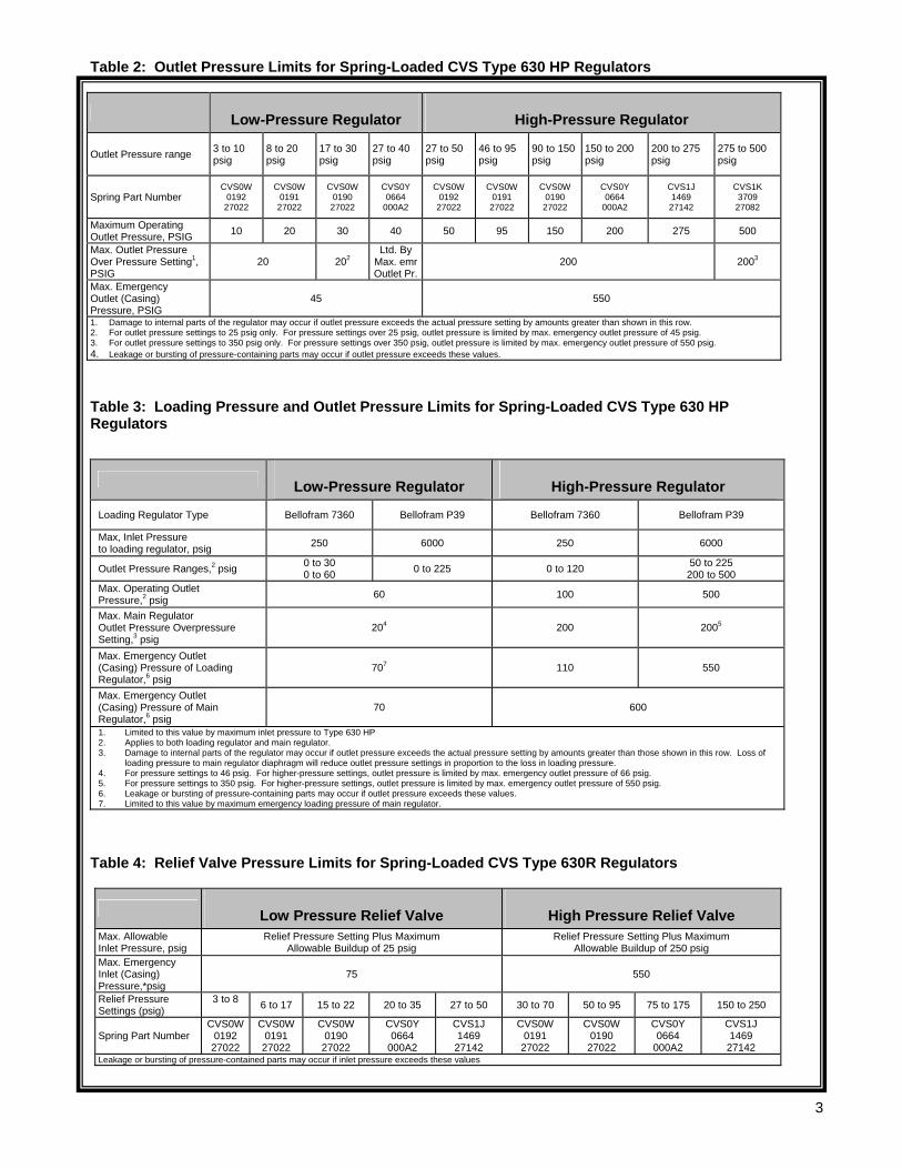
Table 2: Outlet Pressure Limits for Spring-Loaded CVS Type 630 HP Regulators
Low-Pressure Regulator High-Pressure Regulator
Outlet Pressure range 3 to 10 psig
8 to 20 psig
17 to 30 psig
27 to 40 psig
27 to 50 psig
46 to 95 psig
90 to 150 psig
150 to 200 psig
200 to 275 psig
275 to 500 psig
Spring Part Number CVS0W
0192 27022
CVS0W 0191
27022
CVS0W 0190
27022
CVS0Y 0664
000A2
CVS0W 0192
27022
CVS0W 0191
27022
CVS0W 0190
27022
CVS0Y 0664
000A2
CVS1J 1469
27142
CVS1K 3709
27082
Maximum Operating Outlet Pressure, PSIG 10 20 30 40 50 95 150 200 275 500
Max. Outlet Pressure Over Pressure Setting1, PSIG
20 202 Ltd. By
Max. emrOutlet Pr.
200 2003
Max. Emergency Outlet (Casing) Pressure, PSIG
45 550
1. Damage to internal parts of the regulator may occur if outlet pressure exceeds the actual pressure setting by amounts greater than shown in this row. 2. For outlet pressure settings to 25 psig only. For pressure settings over 25 psig, outlet pressure is limited by max. emergency outlet pressure of 45 psig. 3. For outlet pressure settings to 350 psig only. For pressure settings over 350 psig, outlet pressure is limited by max. emergency outlet pressure of 550 psig. 4. Leakage or bursting of pressure-containing parts may occur if outlet pressure exceeds these values. Table 3: Loading Pressure and Outlet Pressure Limits for Spring-Loaded CVS Type 630 HP Regulators
Low-Pressure Regulator High-Pressure Regulator
Loading Regulator Type Bellofram 7360 Bellofram P39 Bellofram 7360 Bellofram P39
Max, Inlet Pressure to loading regulator, psig 250 6000 250 6000
Outlet Pressure Ranges,2 psig 0 to 30 0 to 60 0 to 225 0 to 120 50 to 225
200 to 500 Max. Operating Outlet Pressure,2 psig 60 100 500
Max. Main Regulator Outlet Pressure Overpressure Setting,3 psig
204 200 2005
Max. Emergency Outlet (Casing) Pressure of Loading Regulator,6 psig
707 110 550
Max. Emergency Outlet (Casing) Pressure of Main Regulator,6 psig
70 600
1. Limited to this value by maximum inlet pressure to Type 630 HP 2. Applies to both loading regulator and main regulator. 3. Damage to internal parts of the regulator may occur if outlet pressure exceeds the actual pressure setting by amounts greater than those shown in this row. Loss of
loading pressure to main regulator diaphragm will reduce outlet pressure settings in proportion to the loss in loading pressure. 4. For pressure settings to 46 psig. For higher-pressure settings, outlet pressure is limited by max. emergency outlet pressure of 66 psig. 5. For pressure settings to 350 psig. For higher-pressure settings, outlet pressure is limited by max. emergency outlet pressure of 550 psig. 6. Leakage or bursting of pressure-containing parts may occur if outlet pressure exceeds these values. 7. Limited to this value by maximum emergency loading pressure of main regulator.
Table 4: Relief Valve Pressure Limits for Spring-Loaded CVS Type 630R Regulators
Low Pressure Relief Valve High Pressure Relief Valve Max. Allowable Inlet Pressure, psig
Relief Pressure Setting Plus Maximum Allowable Buildup of 25 psig
Relief Pressure Setting Plus Maximum Allowable Buildup of 250 psig
Max. Emergency Inlet (Casing) Pressure,*psig
75 550
Relief Pressure Settings (psig)
3 to 8 6 to 17 15 to 22 20 to 35 27 to 50 30 to 70 50 to 95 75 to 175 150 to 250
Spring Part Number CVS0W
0192 27022
CVS0W 0191
27022
CVS0W 0190
27022
CVS0Y 0664
000A2
CVS1J 1469
27142
CVS0W 0191
27022
CVS0W 0190
27022
CVS0Y 0664
000A2
CVS1J 1469
27142 Leakage or bursting of pressure-contained parts may occur if inlet pressure exceeds these values
4
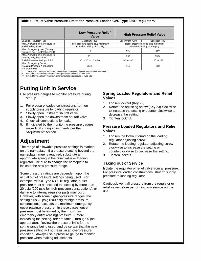
Table 5: Relief Valve Pressure Limits for Pressure-Loaded CVS Type 630R Regulators
Low Pressure Relief Valve High Pressure Relief Valve
Loading Regulator Type Bellofram 7360 Bellowfram 7360 Bellofram P39 Max. Allowable Inlet Pressure to Relief Valve, PSIG
Relief pressure setting plus maximum Allowable buildup of 25 psig
Relief pressure setting plus maximum Allowable buildup of 250 psig
Max. Emergency Inlet (Casing) Pressure * of Relief Valve, PSIG 75 550 550
Max. Allowable Inlet Pressure to Loading Regulator, PSIG 75+ 250 550+
Relief Pressure Settings, PSIG 10 to 20 or 20 to 50 50 to 100 100 to 225 Max. Emergency Outlet (Casing) Pressure * of Loading Regulator, PSIG
75++ 110 250
* Leakage or bursting of pressure-contained parts may occur if pressure exceeds these values. + Limited to this value by maximum emergency inlet pressure of relief valve. ++ Limited to this value by maximum emergency loading pressure of Type 630R
Putting Unit in Service Use pressure gauges to monitor pressure during
startup. 1. For pressure loaded constructions, turn on
supply pressure to loading regulator. 2. Slowly open upstream shutoff valve. 3. Slowly open the downstream shutoff valve. 4. Check all connections for leaks. 5. If indicated by the monitoring pressure gauges,
make final spring adjustments per the “Adjustment” section.
Adjustment The range of allowable pressure settings is marked on the nameplate. If a pressure setting beyond the nameplate range is required, substitute an appropriate spring in the relief valve or loading regulator. Be sure to change the nameplate to indicate the new pressure range. Some pressure ratings are dependent upon the actual outlet pressure settings being used. For example, with a Type 630 HP regulator, outlet pressure must not exceed the setting by more than 20 psig (200 psig for high-pressure constructions), or damage to internal regulator parts may occur. However, with some higher-pressure ranges, the setting plus 20 psig (200 psig for high-pressure constructions) exceeds the maximum emergency outlet (casing) pressure. In these cases, outlet pressure must be limited by the maximum emergency outlet (casing) pressure. Before increasing the setting, refer to table 2 through 5 (as appropriate). Review the pressure limits for the spring range being used, and be certain that the new pressure setting will not result in an overpressure condition. Always use a pressure gauge to monitor pressure when making adjustments.
Spring Loaded Regulators and Relief Valves 1. Loosen locknut (Key 22) 2. Rotate the adjusting screw (Key 23) clockwise
to increase the setting or counter clockwise to decrease the setting.
3. Tighten locknut.
Pressure Loaded Regulators and Relief Valves 1. Loosen the locknut found on the loading
regulator adjusting screw. 2. Rotate the loading regulator adjusting screw
clockwise to increase the setting or counterclockwise to decrease the setting.
3. Tighten locknut.
Taking out of Service Isolate the regulator or relief valve from all pressure. For pressure loaded constructions, shut off supply pressure to loading regulator. Cautiously vent all pressure from the regulator or relief valve before performing any service on the unit.
5
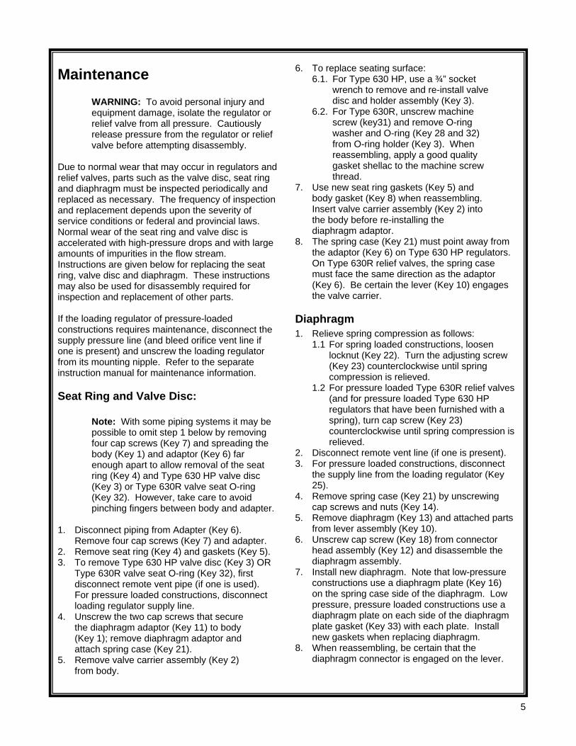
Maintenance
WARNING: To avoid personal injury and equipment damage, isolate the regulator or relief valve from all pressure. Cautiously release pressure from the regulator or relief valve before attempting disassembly.
Due to normal wear that may occur in regulators and relief valves, parts such as the valve disc, seat ring and diaphragm must be inspected periodically and replaced as necessary. The frequency of inspection and replacement depends upon the severity of service conditions or federal and provincial laws. Normal wear of the seat ring and valve disc is accelerated with high-pressure drops and with large amounts of impurities in the flow stream. Instructions are given below for replacing the seat ring, valve disc and diaphragm. These instructions may also be used for disassembly required for inspection and replacement of other parts. If the loading regulator of pressure-loaded constructions requires maintenance, disconnect the supply pressure line (and bleed orifice vent line if one is present) and unscrew the loading regulator from its mounting nipple. Refer to the separate instruction manual for maintenance information.
Seat Ring and Valve Disc:
Note: With some piping systems it may be possible to omit step 1 below by removing four cap screws (Key 7) and spreading the body (Key 1) and adaptor (Key 6) far enough apart to allow removal of the seat ring (Key 4) and Type 630 HP valve disc (Key 3) or Type 630R valve seat O-ring (Key 32). However, take care to avoid pinching fingers between body and adapter.
1. Disconnect piping from Adapter (Key 6).
Remove four cap screws (Key 7) and adapter. 2. Remove seat ring (Key 4) and gaskets (Key 5). 3. To remove Type 630 HP valve disc (Key 3) OR
Type 630R valve seat O-ring (Key 32), first disconnect remote vent pipe (if one is used). For pressure loaded constructions, disconnect loading regulator supply line.
4. Unscrew the two cap screws that secure the diaphragm adaptor (Key 11) to body (Key 1); remove diaphragm adaptor and attach spring case (Key 21).
5. Remove valve carrier assembly (Key 2) from body.
6. To replace seating surface: 6.1. For Type 630 HP, use a ¾” socket
wrench to remove and re-install valve disc and holder assembly (Key 3).
6.2. For Type 630R, unscrew machine screw (key31) and remove O-ring washer and O-ring (Key 28 and 32) from O-ring holder (Key 3). When reassembling, apply a good quality gasket shellac to the machine screw thread.
7. Use new seat ring gaskets (Key 5) and body gasket (Key 8) when reassembling. Insert valve carrier assembly (Key 2) into the body before re-installing the diaphragm adaptor.
8. The spring case (Key 21) must point away from the adaptor (Key 6) on Type 630 HP regulators. On Type 630R relief valves, the spring case must face the same direction as the adaptor (Key 6). Be certain the lever (Key 10) engages the valve carrier.
Diaphragm 1. Relieve spring compression as follows:
1.1 For spring loaded constructions, loosen locknut (Key 22). Turn the adjusting screw (Key 23) counterclockwise until spring compression is relieved.
1.2 For pressure loaded Type 630R relief valves (and for pressure loaded Type 630 HP regulators that have been furnished with a spring), turn cap screw (Key 23) counterclockwise until spring compression is relieved.
2. Disconnect remote vent line (if one is present). 3. For pressure loaded constructions, disconnect
the supply line from the loading regulator (Key 25).
4. Remove spring case (Key 21) by unscrewing cap screws and nuts (Key 14).
5. Remove diaphragm (Key 13) and attached parts from lever assembly (Key 10).
6. Unscrew cap screw (Key 18) from connector head assembly (Key 12) and disassemble the diaphragm assembly.
7. Install new diaphragm. Note that low-pressure constructions use a diaphragm plate (Key 16) on the spring case side of the diaphragm. Low pressure, pressure loaded constructions use a diaphragm plate on each side of the diaphragm plate gasket (Key 33) with each plate. Install new gaskets when replacing diaphragm.
8. When reassembling, be certain that the diaphragm connector is engaged on the lever.
6
9. To ensure proper slack in the diaphragm: 9.1 For constructions using a spring, tighten the
spring case cap screws finger tight only. Compress the spring slightly with the adjusting screw (or cap screw for pressure loaded constructions); then complete the tightening of spring case cap screws and nuts.
9.2 For constructions without a spring, tighten spring case cap screws finger tight only. Remove cap screw (Key 23). Insert a rod in the spring case and push on the assembly to take up the slack; then complete the tightening of the spring case cap screws. Re-install cap screw (Key 23) in spring case.
Nameplate Information When corresponding with your CVS Controls representative about this device, state the model number, pressure range and all other pertinent information found on the nameplate (Key 29). When ordering replacement parts, also specify the complete part number of each part required.
7
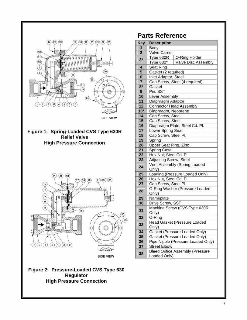
Parts Reference Key Description
1 Body 2 Valve Carrier
Type 630R O-Ring Holder 3* Type 630* Valve Disc Assembly 4 Seat Ring 5 Gasket (2 required) 6 Inlet Adaptor, Steel 7 Cap Screw, Steel (4 required) 8* Gasket 9 Pin, SST 10 Lever Assembly 11 Diaphragm Adaptor 12 Connector Head Assembly 13* Diaphragm, Neoprene 14 Cap Screw, Steel 15 Cap Screw, Steel 16 Diaphragm Plate, Steel Cd. Pl. 17 Lower Spring Seat 18 Cap Screw, Steel Pl. 19 Spring 20 Upper Seat Ring, Zinc 21 Spring Case 22 Hex Nut, Steel Cd. Pl 23 Adjusting Screw, Steel
24 Vent Assembly (Spring Loaded Only)
25 Loading (Pressure Loaded Only) 26 Hex Nut, Steel Cd. Pl. 27 Cap Screw, Steel Pl.
28 O-Ring Washer (Pressure Loaded Only)
29 Nameplate 30 Drive Screw, SST
31 Machine Screw (CVS Type 630R Only)
32 O-Ring
33 Head Gasket (Pressure Loaded Only)
34 Gasket (Pressure Loaded Only) 35 Gasket (Pressure Loaded Only) 36 Pipe Nipple (Pressure Loaded Only) 37 Street Elbow
38 Bleed Orifice Assembly (Pressure Loaded Only)
Figure 1: Spring-Loaded CVS Type 630R Relief Valve
High Pressure Connection
Figure 2: Pressure-Loaded CVS Type 630 Regulator
High Pressure Connection
8
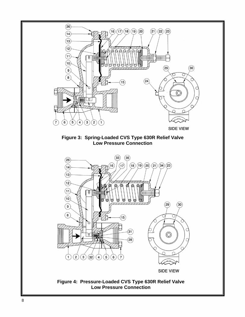
Figure 3: Spring-Loaded CVS Type 630R Relief Valve Low Pressure Connection
Figure 4: Pressure-Loaded CVS Type 630R Relief Valve Low Pressure Connection
9
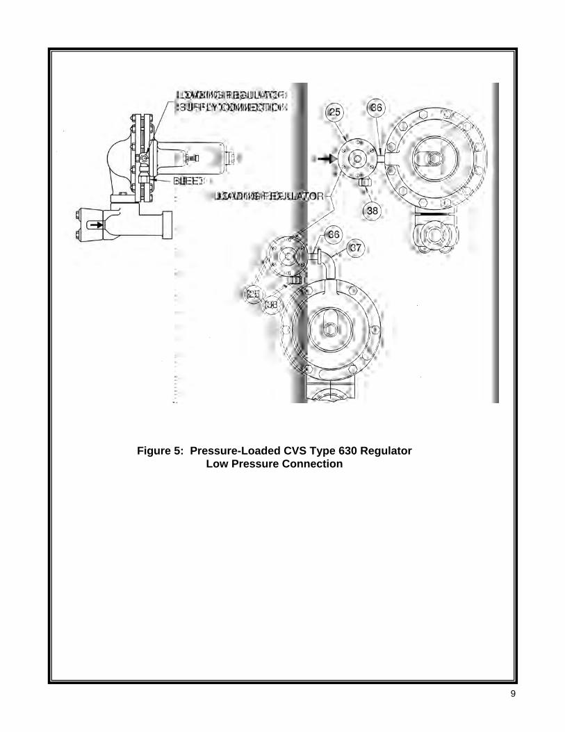
Figure 5: Pressure-Loaded CVS Type 630 Regulator Low Pressure Connection
10
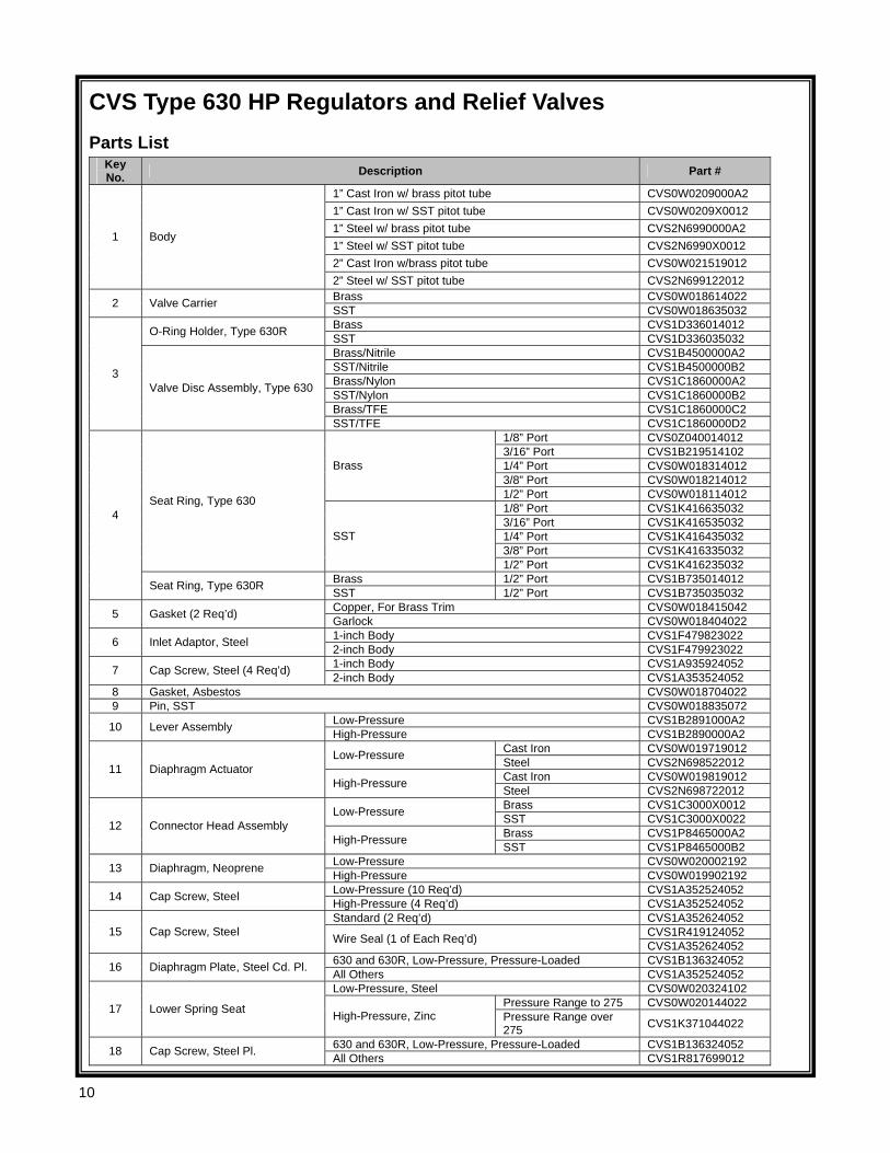
CVS Type 630 HP Regulators and Relief Valves Parts List
Key No. Description Part #
1” Cast Iron w/ brass pitot tube CVS0W0209000A2 1” Cast Iron w/ SST pitot tube CVS0W0209X0012 1” Steel w/ brass pitot tube CVS2N6990000A2 1” Steel w/ SST pitot tube CVS2N6990X0012 2” Cast Iron w/brass pitot tube CVS0W021519012
1 Body
2” Steel w/ SST pitot tube CVS2N699122012 Brass CVS0W018614022 2 Valve Carrier SST CVS0W018635032 Brass CVS1D336014012 O-Ring Holder, Type 630R SST CVS1D336035032 Brass/Nitrile CVS1B4500000A2 SST/Nitrile CVS1B4500000B2 Brass/Nylon CVS1C1860000A2 SST/Nylon CVS1C1860000B2 Brass/TFE CVS1C1860000C2
3 Valve Disc Assembly, Type 630
SST/TFE CVS1C1860000D2 1/8” Port CVS0Z040014012 3/16” Port CVS1B219514102 1/4” Port CVS0W018314012 3/8” Port CVS0W018214012
Brass
1/2” Port CVS0W018114012 1/8” Port CVS1K416635032 3/16” Port CVS1K416535032 1/4” Port CVS1K416435032 3/8” Port CVS1K416335032
Seat Ring, Type 630
SST
1/2” Port CVS1K416235032 Brass 1/2” Port CVS1B735014012
4
Seat Ring, Type 630R SST 1/2” Port CVS1B735035032 Copper, For Brass Trim CVS0W018415042 5 Gasket (2 Req’d) Garlock CVS0W018404022 1-inch Body CVS1F479823022 6 Inlet Adaptor, Steel 2-inch Body CVS1F479923022 1-inch Body CVS1A935924052 7 Cap Screw, Steel (4 Req’d) 2-inch Body CVS1A353524052
8 Gasket, Asbestos CVS0W018704022 9 Pin, SST CVS0W018835072
Low-Pressure CVS1B2891000A2 10 Lever Assembly High-Pressure CVS1B2890000A2 Cast Iron CVS0W019719012 Low-Pressure Steel CVS2N698522012 Cast Iron CVS0W019819012 11 Diaphragm Actuator
High-Pressure Steel CVS2N698722012 Brass CVS1C3000X0012 Low-Pressure SST CVS1C3000X0022 Brass CVS1P8465000A2 12 Connector Head Assembly
High-Pressure SST CVS1P8465000B2 Low-Pressure CVS0W020002192 13 Diaphragm, Neoprene High-Pressure CVS0W019902192 Low-Pressure (10 Req’d) CVS1A352524052 14 Cap Screw, Steel High-Pressure (4 Req’d) CVS1A352524052 Standard (2 Req’d) CVS1A352624052
CVS1R419124052 15 Cap Screw, Steel Wire Seal (1 of Each Req’d) CVS1A352624052 630 and 630R, Low-Pressure, Pressure-Loaded CVS1B136324052 16 Diaphragm Plate, Steel Cd. Pl. All Others CVS1A352524052 Low-Pressure, Steel CVS0W020324102
Pressure Range to 275 CVS0W020144022 17 Lower Spring Seat High-Pressure, Zinc Pressure Range over 275 CVS1K371044022
630 and 630R, Low-Pressure, Pressure-Loaded CVS1B136324052 18 Cap Screw, Steel Pl. All Others CVS1R817699012
11
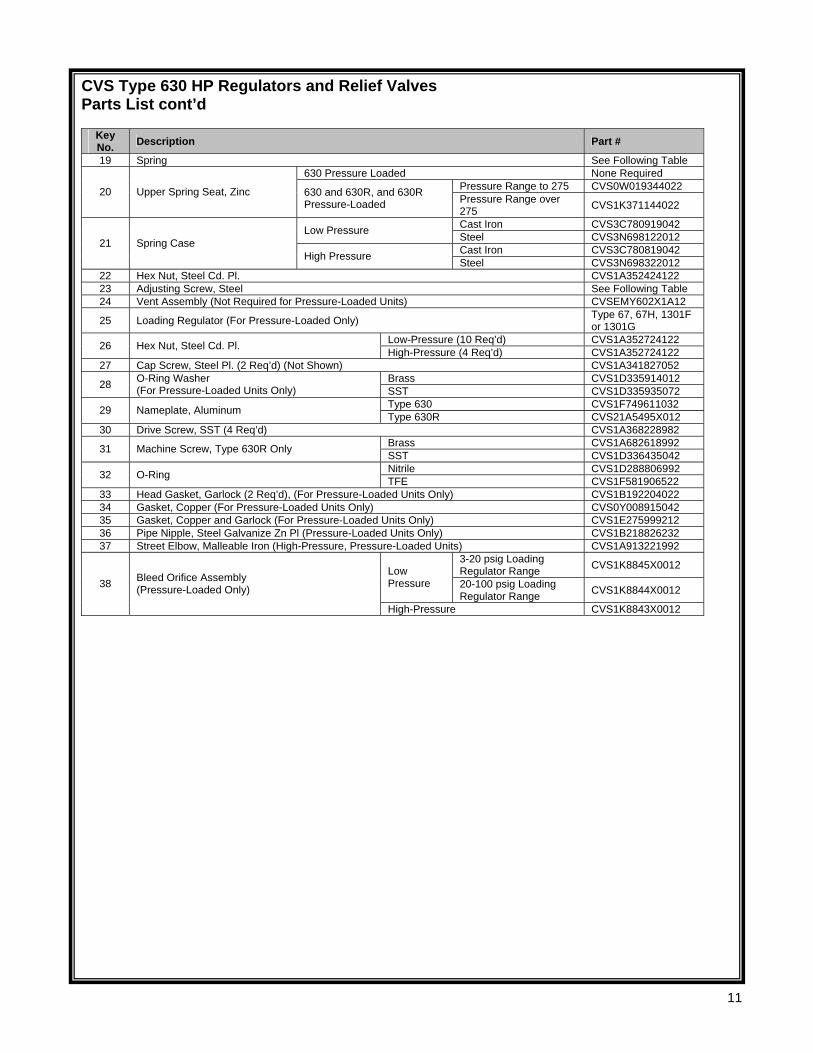
CVS Type 630 HP Regulators and Relief Valves Parts List cont’d
Key No. Description Part #
19 Spring See Following Table 630 Pressure Loaded None Required
Pressure Range to 275 CVS0W019344022 20 Upper Spring Seat, Zinc 630 and 630R, and 630R Pressure-Loaded Pressure Range over
275 CVS1K371144022
Cast Iron CVS3C780919042 Low Pressure Steel CVS3N698122012 Cast Iron CVS3C780819042 21 Spring Case
High Pressure Steel CVS3N698322012 22 Hex Nut, Steel Cd. Pl. CVS1A352424122 23 Adjusting Screw, Steel See Following Table 24 Vent Assembly (Not Required for Pressure-Loaded Units) CVSEMY602X1A12
25 Loading Regulator (For Pressure-Loaded Only) Type 67, 67H, 1301F or 1301G
Low-Pressure (10 Req’d) CVS1A352724122 26 Hex Nut, Steel Cd. Pl. High-Pressure (4 Req’d) CVS1A352724122 27 Cap Screw, Steel Pl. (2 Req’d) (Not Shown) CVS1A341827052
Brass CVS1D335914012 28 O-Ring Washer (For Pressure-Loaded Units Only) SST CVS1D335935072
Type 630 CVS1F749611032 29 Nameplate, Aluminum Type 630R CVS21A5495X012 30 Drive Screw, SST (4 Req’d) CVS1A368228982
Brass CVS1A682618992 31 Machine Screw, Type 630R Only SST CVS1D336435042 Nitrile CVS1D288806992 32 O-Ring TFE CVS1F581906522
33 Head Gasket, Garlock (2 Req’d), (For Pressure-Loaded Units Only) CVS1B192204022 34 Gasket, Copper (For Pressure-Loaded Units Only) CVS0Y008915042 35 Gasket, Copper and Garlock (For Pressure-Loaded Units Only) CVS1E275999212 36 Pipe Nipple, Steel Galvanize Zn Pl (Pressure-Loaded Units Only) CVS1B218826232 37 Street Elbow, Malleable Iron (High-Pressure, Pressure-Loaded Units) CVS1A913221992
3-20 psig Loading Regulator Range CVS1K8845X0012 Low
Pressure 20-100 psig Loading Regulator Range CVS1K8844X0012 38 Bleed Orifice Assembly
(Pressure-Loaded Only)
High-Pressure CVS1K8843X0012
12
Rev 0 03/05 Printed in Canada
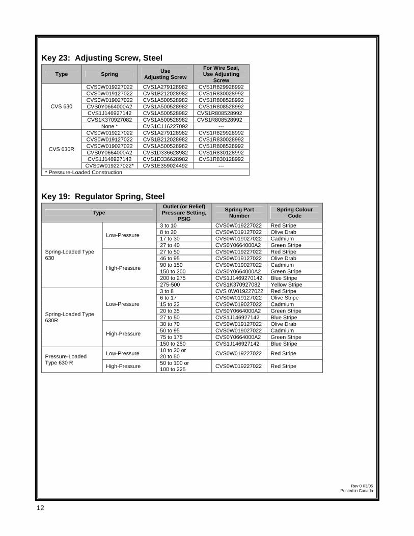
Key 23: Adjusting Screw, Steel
Type Spring Use Adjusting Screw
For Wire Seal, Use Adjusting
Screw CVS0W019227022 CVS1A279128982 CVS1R829928992 CVS0W019127022 CVS1B212028982 CVS1R830028992 CVS0W019027022 CVS1A500528982 CVS1R808528992 CVS0Y0664000A2 CVS1A500528982 CVS1R808528992 CVS1J146927142 CVS1A500528982 CVS1R808528992 CVS1K370927082 CVS1A500528982 CVS1R808528992
CVS 630
None * CVS1C116227092 --- CVS0W019227022 CVS1A279128982 CVS1R829928992 CVS0W019127022 CVS1B212028982 CVS1R830028992 CVS0W019027022 CVS1A500528982 CVS1R808528992 CVS0Y0664000A2 CVS1D336628982 CVS1R830128992 CVS1J146927142 CVS1D336628982 CVS1R830128992
CVS 630R
CVS0W019227022* CVS1E359024492 --- * Pressure-Loaded Construction
Key 19: Regulator Spring, Steel
Type Outlet (or Relief) Pressure Setting,
PSIG
Spring Part Number
Spring Colour Code
3 to 10 CVS0W019227022 Red Stripe 8 to 20 CVS0W019127022 Olive Drab 17 to 30 CVS0W019027022 Cadmium Low-Pressure
27 to 40 CVS0Y0664000A2 Green Stripe 27 to 50 CVS0W019227022 Red Stripe 46 to 95 CVS0W019127022 Olive Drab 90 to 150 CVS0W019027022 Cadmium 150 to 200 CVS0Y0664000A2 Green Stripe 200 to 275 CVS1J1469270142 Blue Stripe
Spring-Loaded Type 630
High-Pressure
275-500 CVS1K370927082 Yellow Stripe 3 to 8 CVS 0W019227022 Red Stripe 6 to 17 CVS0W019127022 Olive Stripe 15 to 22 CVS0W019027022 Cadmium 20 to 35 CVS0Y0664000A2 Green Stripe
Low-Pressure
27 to 50 CVS1J146927142 Blue Stripe 30 to 70 CVS0W019127022 Olive Drab 50 to 95 CVS0W019027022 Cadmium 75 to 175 CVS0Y0664000A2 Green Stripe
Spring-Loaded Type 630R
High-Pressure
150 to 250 CVS1J146927142 Blue Stripe
Low-Pressure 10 to 20 or 20 to 50 CVS0W019227022 Red Stripe Pressure-Loaded
Type 630 R High-Pressure 50 to 100 or 100 to 225 CVS0W019227022 Red Stripe
CVS Controls Ltd. 1 Process Management and Instrumentation
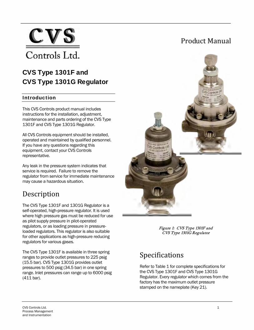
CVS Type 1301F and CVS Type 1301G Regulator
Introduction
This CVS Controls product manual includes instructions for the installation, adjustment, maintenance and parts ordering of the CVS Type 1301F and CVS Type 1301G Regulator.
All CVS Controls equipment should be installed, operated and maintained by qualified personnel. If you have any questions regarding this equipment, contact your CVS Controls representative.
Any leak in the pressure system indicates that service is required. Failure to remove the regulator from service for immediate maintenance may cause a hazardous situation.
Description The CVS Type 1301F and 1301G Regulator is a self-operated, high-pressure regulator. It is used where high pressure gas must be reduced for use as pilot supply pressure in pilot-operated regulators, or as loading pressure in pressure-loaded regulators. This regulator is also suitable for other applications as high-pressure reducing regulators for various gases.
The CVS Type 1301F is available in three spring ranges to provide outlet pressures to 225 psig (15.5 bar). CVS Type 1301G provides outlet pressures to 500 psig (34.5 bar) in one spring range. Inlet pressures can range up to 6000 psig (411 bar).
Product Manual
Figure 1: CVS Type 1301F and CVS Type 1301G Regulator
Specifications Refer to Table 1 for complete specifications for the CVS Type 1301F and CVS Type 1301G Regulator. Every regulator which comes from the factory has the maximum outlet pressure stamped on the nameplate (Key 21).
CVS Controls Ltd. Product Manual: CVS Type 1301F and 1301G Regulator
CVS Controls Ltd. 2 Process Management and Instrumentation
Specifications
Installation
WARNING Do not install any pressure equipment where service conditions exceed the manufacturer’s specifications. Over pressuring of regulator may result in leakage, equipment damage or personal injury. Excessive pressure can cause the pressure-containing parts to burst, or accumulated gas to explode. Always conform to applicable industry codes and regulations.
Prior to installation check the regulator and all tubing and piping for damage and remove any foreign material.
The regulator can be installed in any position.
WARNING A regulator may vent some gas into the atmosphere. When used in hazardous gas service, the regulator should be vented to a remote, safe location. If not properly vented, hazardous gas may accumulate and cause fire or explosion.
Prior to being shipped from CVS Controls, the pressure setting for each regulator is set according to customer specifications. If no setting is specified, the outlet pressure is set at the midpoint of the regulator spring range.
If pressure adjustment is required, refer to the “Start Up” section of this guide. Always check the spring section to ensure it is correct for the application.
Begin installation by applying pipe compound to the pipeline threads. Connect inlet piping or tubing to the ¼-inch NPT screwed connection marked “In” as well as outlet piping or tubing to one of the ¼-inch NPT screwed connections marked “Out”. Install a pressure gauge or pipe plug in the unused outlet connection.
To maintain continuous operation during inspection or maintenance of the regulator, install a three-valve bypass around the regulator.
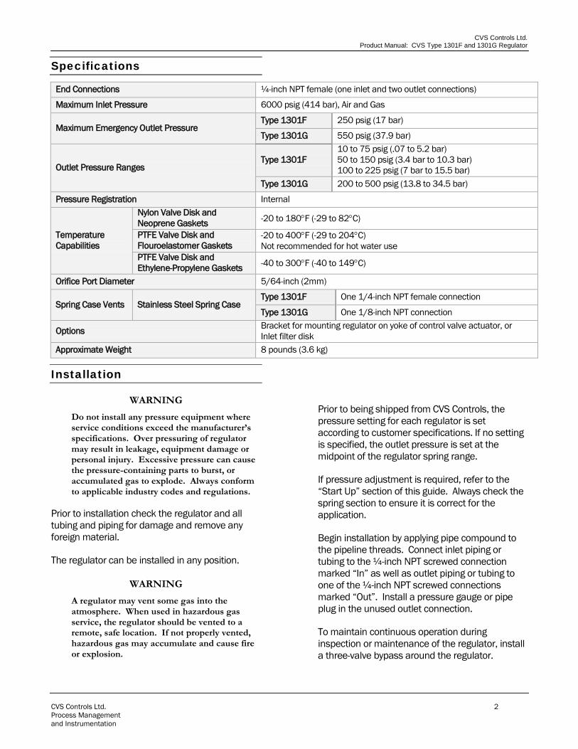
End Connections ¼-inch NPT female (one inlet and two outlet connections)
Maximum Inlet Pressure 6000 psig (414 bar), Air and Gas
Maximum Emergency Outlet Pressure Type 1301F 250 psig (17 bar)
Type 1301G 550 psig (37.9 bar)
Outlet Pressure Ranges Type 1301F
10 to 75 psig (.07 to 5.2 bar) 50 to 150 psig (3.4 bar to 10.3 bar) 100 to 225 psig (7 bar to 15.5 bar)
Type 1301G 200 to 500 psig (13.8 to 34.5 bar)
Pressure Registration Internal
Temperature Capabilities
Nylon Valve Disk and Neoprene Gaskets -20 to 180°F (-29 to 82°C)
PTFE Valve Disk and Flouroelastomer Gaskets
-20 to 400°F (-29 to 204°C) Not recommended for hot water use
PTFE Valve Disk and Ethylene-Propylene Gaskets -40 to 300°F (-40 to 149°C)
Orifice Port Diameter 5/64-inch (2mm)
Spring Case Vents Stainless Steel Spring Case Type 1301F One 1/4-inch NPT female connection
Type 1301G One 1/8-inch NPT connection
Options Bracket for mounting regulator on yoke of control valve actuator, or Inlet filter disk
Approximate Weight 8 pounds (3.6 kg)
CVS Controls Ltd Product Manual: CVS Type 1301F and 1301G Regulator
CVS Controls Ltd. 3 Process Management and Instrumentation
Start Up
When the regulator has been installed and downstream equipment has been adjusted, the regulator can be pressurized.
Using gauges to monitor the pressure slowly open upstream and downstream block valves during start up and while performing any adjustments.
If adjustment is required loosen the locknut (Key 11) and turn the adjusting screw (Key 1) either clockwise to increase the set pressure or counter-clockwise to decrease the set pressure. Monitor the pressure during the adjustment using pressure gauges. When the adjustment is complete, tighten the locknut. If the desired outlet pressure is not within the range specified by the regulator spring, refer to the “Maintenance” section of this guide and install the spring that suits the desired range.
Shutdown
To shutdown the regulator, close the upstream shutoff valve, then close the downstream shutoff valve. Open the vent valves between the regulator and the downstream shutoff valve then open the vent between the regulator and the upstream shutoff valve. If vent valves have not been installed, safely bleed off both inlet and outlet pressures and ensure that the regulator contains no pressure.
Maintenance
Regulator maintenance should be done as required by local regulations, and as necessary due to normal wear and tear. Frequency of inspection and parts replacement should be done according to severity of service.
WARNING Prior to performing any maintenance or disassembly, isolate the regulator from system pressure and relieve all internal pressure. Performing maintenance while the regulator is pressurized could result in injury, equipment damage or explosion of accumulated gas.
Disassembly These steps describe how to completely disassemble the regulator. To perform inspection or replace parts, complete only the steps necessary for the specific job. Refer to Figure 2 for key numbers unless otherwise indicated.
1. Loosen the locknut (Key 11) and release spring compression by turning the adjusting screw (Key 1) counterclockwise.
2. Remove the bottom cap (Key 9), bottom cap gasket (Key 8) and spring (Key 3).
3. Remove the valve disk assembly (Key 19) from the yoke (Key 17).
4. Remove the valve disk collar (Key 10) from the valve disk assembly.
5. Remove the spring case cap screws (Key 5) and separate the spring case (Key 2) from the regulator body (Key 6).
6. Remove the upper spring seat (Key 12) and spring (Key 3).
7. Refer to Figure 3 and unscrew the diaphragm locknut (Key 4). Remove the diaphragm plate (Key 13), the two diaphragms (Key 13) and the diaphragm plate gasket (Key 7).
8. Remove the yoke screws (Key 15) and lift the lower and upper halves of the yoke out of the body.
9. Unscrew the orifice (Key 18) and examine the seating edge. If the seat is worn or nicked, replace with a new part.
CVS Controls Ltd. Product Manual: CVS Type 1301F and 1301G Regulator
CVS Controls Ltd. 4 Process Management and Instrumentation
Assembly These are complete instructions assuming the regulator was fully disassembled. If the regulator was only partially disassembled, start at the appropriate step. Refer to Figure 2 for key numbers.
1. Screw the orifice (Key 18) into the regulator then insert both halves of the yoke (Key 17). Fasten the yoke together with the cap screws (Key 15).
2. The valve disk assembly (Key 19) has two disks (one on each end). Inspect both disks and select which one will be used. Thread the assembly into the yoke so that the disk to be used is against the orifice. Thread the valve disk collar (Key 10) on to the exposed end of the valve disk assembly.
3. Place the bottom cap gasket (Key 8) onto the bottom cap (Key 9), then insert the spring (Key 3) into the bottom cap and thread the assembly into the regulator.
4. Place the body gasket (Key 16) on the regulator body (Key 6).
5. Refer to Figure 3 and place the diaphragm plate gasket (Key 7), the two diaphragms (Key 14) and the diaphragm plate (Key 13) onto the yoke (Key 17). Ensure the diaphragm convolutions are toward the spring and thread the diaphragm locknut (Key 4) onto the yoke.
6. Place the regulator spring (Key 2) and upper spring seat (Key 12) onto the diaphragm plate.
7. Position the spring case (Key 2) over the spring and on the regulator body. Line up the spring case vent or vents, insert the cap screws (Key 5) and tighten them by hand.
8. Thread the adjusting screw (Key 1) and locknut (Key 11) into the spring case so the spring is just slightly compressed. Securely tighten the cap screws (Key 5) and refer to the “Start Up” instructions for proper adjustment procedures.
Parts Ordering
All pertinent information regarding the regulator is stamped on the bottom cap and on the nameplate. Please refer to this information when corresponding with CVS Controls regarding parts or service for your CVS Type 1301F and CVS Type 1301G Regulator.
When ordering replacement parts, please provide the complete part number from the enclosed parts list.
CVS Controls Ltd Product Manual: CVS Type 1301F and 1301G Regulator
CVS Controls Ltd. 5 Process Management and Instrumentation
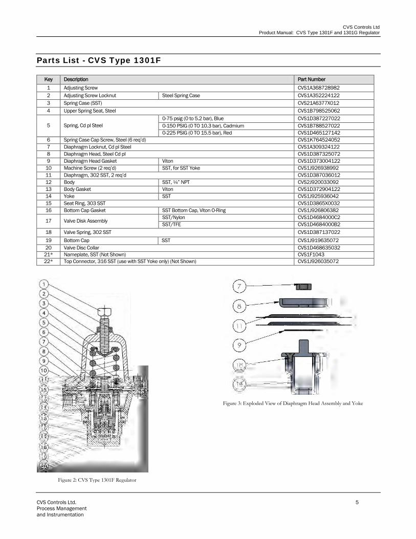
Parts List - CVS Type 1301F
Key Description Part Number 1 Adjusting Screw CVS1A368728982 2 Adjusting Screw Locknut Steel Spring Case CVS1A352224122 3 Spring Case (SST) CVS21A6377X012 4 Upper Spring Seat, Steel CVS1B798525062
5 Spring, Cd pl Steel 0-75 psig (0 to 5.2 bar), Blue CVS1D387227022 0-150 PSIG (0 TO 10.3 bar), Cadmium CVS1B788527022 0-225 PSIG (0 TO 15.5 bar), Red CVS1D465127142
6 Spring Case Cap Screw, Steel (6 req’d) CVS1K764524052 7 Diaphragm Locknut, Cd pl Steel CVS1A309324122 8 Diaphragm Head, Steel Cd pl CVS1D387325072 9 Diaphragm Head Gasket Viton CVS1D373004122
10 Machine Screw (2 req’d) SST, for SST Yoke CVS1J926938992 11 Diaphragm, 302 SST, 2 req’d CVS1D387036012 12 Body SST, ¼” NPT CVS2J920033092 13 Body Gasket Viton CVS1D372904122 14 Yoke SST CVS1J925936042 15 Seat Ring, 303 SST CVS1D3865X0032 16 Bottom Cap Gasket SST Bottom Cap, Viton O-Ring CVS1J926806382
17 Valve Disk Assembly SST/Nylon CVS1D4684000C2 SST/TFE CVS1D4684000B2
18 Valve Spring, 302 SST CVS1D387137022 19 Bottom Cap SST CVS1J919635072 20 Valve Disc Collar CVS1D468635032
21* Nameplate, SST (Not Shown) CVS1F1043 22* Top Connector, 316 SST (use with SST Yoke only) (Not Shown) CVS1J926035072
Figure 3: Exploded View of Diaphragm Head Assembly and Yoke
Figure 2: CVS Type 1301F Regulator
CVS Controls Ltd Product Manual: CVS Type 1301F and 1301G Regulator
CVS Controls Ltd. 6 Process Management and Instrumentation
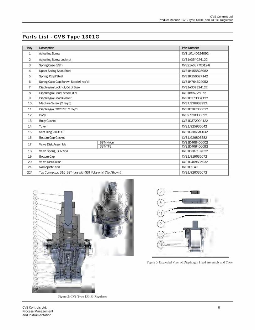
Parts List - CVS Type 1301G
Key Description Part Number
1 Adjusting Screw CVS 1K140624092
2 Adjusting Screw Locknut CVS1A354024122
3 Spring Case (SST) CVS21A6377X012-G
4 Upper Spring Seat, Steel CVS1K155828982
5 Spring, Cd pl Steel CVS1K156027142
6 Spring Case Cap Screw, Steel (6 req’d) CVS1K764524052
7 Diaphragm Locknut, Cd pl Steel CVS1A309324122
8 Diaphragm Head, Steel Cd pl CVS1K55725072 9 Diaphragm Head Gasket CVS1D373004122
10 Machine Screw (2 req’d) CVS1J926938992
11 Diaphragm, 302 SST, 2 req’d CVS1D387036012
12 Body CVS2J920033092
13 Body Gasket CVS1D372904122
14 Yoke CVS1J925936042
15 Seat Ring, 303 SST CVS1D3865X0032
16 Bottom Cap Gasket CVS1J926806382
17 Valve Disk Assembly SST/Nylon CVS1D4684000C2 SST/TFE CVS1D4684000B2
18 Valve Spring, 302 SST CVS1D387137022
19 Bottom Cap CVS1J919635072
20 Valve Disc Collar CVS1D468635032 21 Nameplate, SST CVS1F1043
22* Top Connector, 316 SST (use with SST Yoke only) (Not Shown) CVS1J926035072
Figure 2: CVS Type 1301G Regulator
Figure 3: Exploded View of Diaphragm Head Assembly and Yoke
CVS Controls Ltd Product Manual: CVS Type 1301F and 1301G Regulator
CVS Controls Ltd. 7 Process Management and Instrumentation
Notes
CVS Controls LtdProduct Manual: CVS Type 1301F and 1301G Regulator
CVS Controls Ltd. 8 Process Management and Instrumentation
Head Office 3900 – 101 Street Edmonton, Alberta, Canada T6E 0A5 Office: (780) 437-3055 Fax: (780) 436-5461
Website: www.cvs-controls.com E-Mail: [email protected] Printed in Canada Rev 1, April 09
Calgary Sales Office 205, 2323 – 32 Avenue NE Calgary, Alberta, Canada T2E 6Z3 Office: (403) 250-1416 Fax: (403) 291-9487
CVS Controls Ltd. strives for the highest levels of quality and accuracy. The information included in this publication is presented for informational purposes only. CVS Controls Ltd. reserves the right to modify or change, and improve design, process, and specifications without written notice. Under no circumstance is the information contained to be interpreted to be a guarantee/warranty with regard to our products or services, applicability or use. Selection, use and maintenance are the sole responsibility of the end user and purchaser. CVS Controls assumes no liability for the selection use and maintenance of any product.
Global Supply Line Sole Agents Australia, New Zealand & PNG
www.globalsupplyline.com.au