Embed Size (px)
Citation preview
CVO-312
Installation and Operation
Notice:
The CVO-312 is a Legacy Item and is no longer in production.
Fully replaced by the superior HDVO-318.
Last Updated 09/03/2014
Table of Contents
WARRANTY……………………………………………………………………………………..5
DISCLAIMER…………………………………………………………………………………....5
IMPORTANT NOTES …………………………………………………………………………..5
1. Overview ……………………………………………………………………………………….6
2. Specifications…………………………………………………………………………………..7
3. Installation……………………………………………………………………………………..9 3.1 Physical Installation……………………………………………………………………...11 3.2 DL-08/09 System Association …………………………………………………………...12 3.3 DL-08/09 Selection of Overlay Monitor Items…………………………………………..12 3.4 Touch Calibration and Initial Setup……………………………………………………...12
4. Video Screen Configuration………………………………………………………………....16 4.1 Selecting Video Channel………………………………………………………………....17 4.2 Main Screen Setup Menu………………………………………………………………...18
CVO-312 with CAN and RS485 data sources…………………………………………...19 CVO-312 with DL-08/09 data source…………………………………………………....23
4.3 Video Options …………………………………………………………………………....26 4.4 Editing Lines……………………………………………………………………………..29
Position and Size………………………………………………………………………....29 Line Appearance Menu…………………………………………………………………..33
4.5 Editing Items……………………………………………………………………………..35 Position and Size………………………………………………………………………....35 Item Type………………………………………………………………………………...37 Style ……………………………………………………………………………………...39 Limits …………………………………………………………………………………….41
5. On-Screen Help Documentation…………………………………………………………….44 5.1 Opening Help Document Viewer………………………………………………………...45
Legacy Item: CVO-312 Manual
www.skipline.com Page 1
5.2 Viewing Help Documents………………………………………………………………..46
6. Glass Cockpit Features……………………………………………………………………....50 6.1 Tab Customization……………………………………………………………………….51
6.1.1 Entering Tab Edit Mode…………………………………………………………....51 6.1.2 Moving Tabs ……………………………………………………………………….52 6.1.3 Inserting New Tabs………………………………………………………………...54 6.1.4 Deleting a Tab……………………………………………………………………...54 6.1.5 Tab Editing………………………………………………………………………....55 6.1.6 Layout Types……………………………………………………………………….58
Freeform Layouts…………………………………………………………………….58 Grid Layouts ………………………………………………………………………....59 Custom Grid Layouts………………………………………………………………...60
6.1.7 Adding Items……………………………………………………………………….61 6.1.8 Editing Freeform Items…………………………………………………………….62
6.2 Item Type Descriptions…………………………………………………………………..63 6.2.1 Rates and Sensor Item Descriptions ……………………………………………….63
Speed ……………………………………………………………………………….65 Paint Usage/Rate/Footage…………………………………………………………....65 Bead Usage/Rates …………………………………………………………………....65 Temperatures………………………………………………………………………....66 Analog Sensors ……………………………………………………………………....66 Digital Sensors……………………………………………………………………….67 Thermocouple Sensors……………………………………………………………….67
6.2.2 Proportional Outputs …………………………………………………………………67 6.2.3 Simple Outputs …………………………………………………………………….69 6.2.5 Controllers ………………………………………………………………………....71 6.2.6 Indicators…………………………………………………………………………...72
7. System Setup …………………………………………………………………………………75 7.1 Entering Setup…………………………………………………………………………....75 7.2 Reset to Factory Setup …………………………………………………………………...76 7.3 Change Address ………………………………………………………………………….77
Legacy Item: CVO-312 Manual
www.skipline.com Page 2
7.4 System Diagnostics……………………………………………………………………....78 7.5 Manage Help Documents………………………………………………………………...79 7.6 Factory Settings ………………………………………………………………………….81
7.6.1 Gun Widths and Colors…………………………………………………………….81 7.6.2 Gun Offsets ………………………………………………………………………...83 7.6.3 Gun Delays………………………………………………………………………....87 7.6.4 Calibration Numbers……………………………………………………………….90
7.7 Operator Settings ………………………………………………………………………...91 7.7.1 Stripe Length Correction…………………………………………………………...92 7.7.2 Distance Calibration………………………………………………………………..94 7.7.3 Pump Calibration …………………………………………………………………..97 7.7.4 Registration Calibration…………………………………………………………..100
7.8 Operating Value Sets…………………………………………………………………....105
8. System Updates ……………………………………………………………………………..108
9. Troubleshooting……………………………………………………………………………..109
9.1 Video and Overlay Troubleshooting…………………………………………………....109
Appendix A: DL-08/09 Auto-Connect………………………………………………………..110 Auto Connect ……………………………………………………………………………….110
Appendix B: DL-08/09 Selecting Video Overlay Items……………………………………...113
Video Overlay Setup………………………………………………………………………..113
Legacy Item: CVO-312 Manual
www.skipline.com Page 3
THIS EQUIPMENT IS FOR +12 VOLT NEGATIVE GROUND SYSTEMS ONLY! Do not connect to positive ground systems or damage will result.
Avoid locations which are exposed to excessive vibration, direct sunlight,
moisture, and extremes of temperature.
When installing, be sure to allow room for cables to plug in at the front of
the CVO-312.
The CVO-312 is not waterproof. Outboard installations must be protected by
a waterproof box or cover. Such enclosures need a small vent to prevent moisture
accumulation.
Be sure to use a fuse in the 12 volt supply wire. If the volt branch that feeds
the CVO-312 is already fused, ensure that there are at least two amps reserved in
the installed fuse rating for the CVO-312.
Legacy Item: CVO-312 Manual
www.skipline.com Page 4
WARRANTY
The CVO-312 product is covered by a 30-day return for refund satisfaction guarantee. Buyer is responsible for determining suitability of this product for intended application
prior to engaging in any contract that would rely on product functionality. This unit is also covered by a limited one year warranty. Products with defects in
workmanship will be repaired or replaced at the sole discretion of Skip-Line, Inc. without charge for up to one year from date of invoice.
DISCLAIMER All electronic equipment is subject to failure due to:
Unanticipated use, non-compatibility of accessories, stress by mechanical vibration, electrical spikes, exposure to intermittent, poorly regulated, highly inductive, or noisy power sources, overlord, temperature extremes, induced load-dump and welding currents, insulation chafing, improper wiring, poor cable routing, or stressed mounting. This device is not rated for exposure to liquids. Contact with water or other fluids may cause moisture intrusion, corrosion, and device failure.
All computerized systems can fail. Skip-Line, Inc. will not be held responsible or liable for any loss as a result of the use of this device, including but not limited to loss of time, money, opportunity, or personal injury. In no case shall Skip-Line, Inc. be responsible beyond the purchase price of this product.
IMPORTANT NOTES Not all CVO-312 units have exactly the same appearance, functionality, or graphical
style. Some graphics contained in this manual may show patterns, functions, or features that are not installed on every unit and should not be relied upon for operational decisions.
Some functionality of this device depends on the proper operation, calibration, and functionality of other devices in the Skip-Line product line. Some functionality shown in the manual may require purchase of further devices.
Contents of this manual are subject to change without notice.
Legacy Item: CVO-312 Manual
www.skipline.com Page 5
1. Overview The CVO-312 Video Overlay and Crosshair Generator is an advanced device that provides both monitoring and video guidance capabilities in a single unit. It improves crew safety by allowing the driver to keep eyes on the road with minimal need to look away from the video guidance monitor.
This device can receive overlay data from several sources. While much of the information is the same, each data source has different information display capabilities.
● A DL-08 or DL-09 Data Logging and Monitoring System, which provides the real-time paint and beads information via wireless connection.
● An SM-5 skip timer system (RS485). ● An SC-12 skip timer system (CAN).
Devices required for full CVO-312 functionality include:
● A vehicle with a correctly functioning and calibrated skip-timer system. ● A data source for Video Overlay, which may be one of the following: ● A DL-08 or DL-09 Laptop or Tablet PC with the Skip-Line Data Logger software
installed. ● An SM-5 or SC-12 skip timer system (via direct serial cable connection). ● A USB touch monitor with either NTSC (Composite) or HDMI video inputs.
If you do not have any of these required devices, your CVO-312 may not have full functionality. Please contact your OEM or Skip-Line with any questions. Before using the system or powering it with paint marking equipment, read all warnings listed at the beginning of this manual and double check all power and signal connections.
Legacy Item: CVO-312 Manual
www.skipline.com Page 6
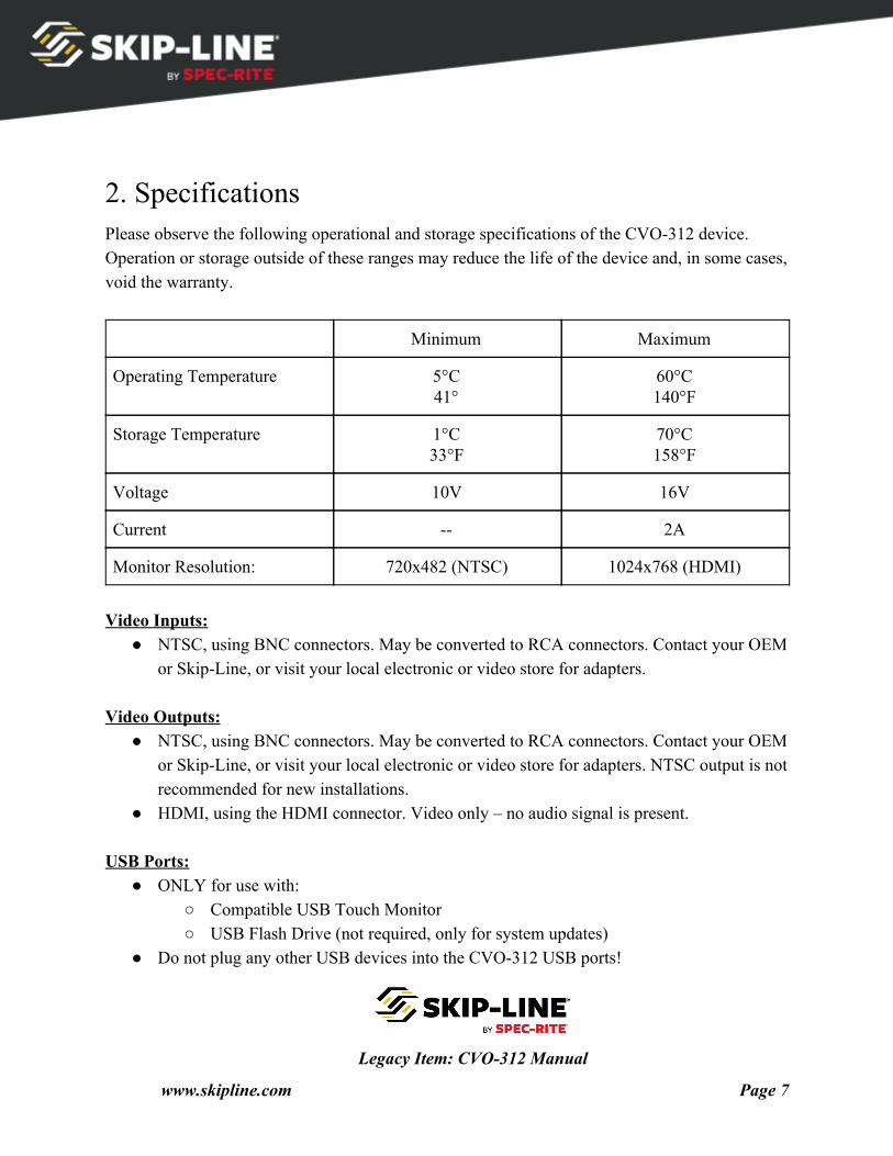
2. Specifications Please observe the following operational and storage specifications of the CVO-312 device. Operation or storage outside of these ranges may reduce the life of the device and, in some cases, void the warranty.
Minimum Maximum
Operating Temperature 5°C 41°
60°C 140°F
Storage Temperature 1°C 33°F
70°C 158°F
Voltage 10V 16V
Current -- 2A
Monitor Resolution: 720x482 (NTSC) 1024x768 (HDMI)
Video Inputs:
● NTSC, using BNC connectors. May be converted to RCA connectors. Contact your OEM or Skip-Line, or visit your local electronic or video store for adapters.
Video Outputs:
● NTSC, using BNC connectors. May be converted to RCA connectors. Contact your OEM or Skip-Line, or visit your local electronic or video store for adapters. NTSC output is not recommended for new installations.
● HDMI, using the HDMI connector. Video only – no audio signal is present. USB Ports:
● ONLY for use with: ○ Compatible USB Touch Monitor ○ USB Flash Drive (not required, only for system updates)
● Do not plug any other USB devices into the CVO-312 USB ports!
Legacy Item: CVO-312 Manual
www.skipline.com Page 7
● Recommended cable length: 6'. ● Maximum USB port current draw: 100mA.
CAN Port:
● RJ45 connector, for connection to an SC-12 Hub device only (unless otherwise directed in documentation from Skip-Line).
● Compatible with standard network patch cables. ● Never connect this port to anything other than a Skip-Line SC-12 skip timer system –
damage to the CVO-312 and/or other equipment may result. RS485 Port:
● RJ11 connector, for connection to an SM-5 skip timer system. ● Requires six conductor RJ11 plug and cable. Follow the standard Skip- Line wiring
pattern only. ● Never connect to telephone or networking equipment – damage to the CVO-312 and/or
other equipment may result. Wireless:
● RP-SMA (Reverse-Polarity SMA) connector. ● Any 2.4GHz antenna is compatible. ● In the event the installation location does not have sufficient wireless signal strength, use
a 50-ohm extension cable or a 2.4GHz WiFi external antenna with an attached cable. Contact your OEM or Skip- Line, or visit your local electronics store.
Legacy Item: CVO-312 Manual
www.skipline.com Page 8
3. Installation Installation of the CVO-312 requires the following before starting:
● CVO-312 mounting location ○ USB ports should be accessible ○ Ensure it is mounted in a location that does not expose cable connectors to
impacts or the environment. ● Touch monitor mounting location and method
○ Ensure mounting method is safe, does not impair driver view, and meets legal requirements when stowed for travel.
● Video cables routed from cameras to the selected mounting location. ● Power routed to the mounting location.
Important Note!
Things to avoid during installation:
● Do not connect power to the device or monitor until all other connections have been made.
● Do not connect the USB cable from the touchscreen monitor to the data logger PC.
● No software driver installation is necessary for this system – do not install ANY software on the Skip-Line Data Logger laptop or tablet PC while installing this device.
Before continuing, please refer to Figure 1 and Figure 2 (on the next page) to become familiar with the connector labeling of the CVO-312.
Legacy Item: CVO-312 Manual
www.skipline.com Page 9
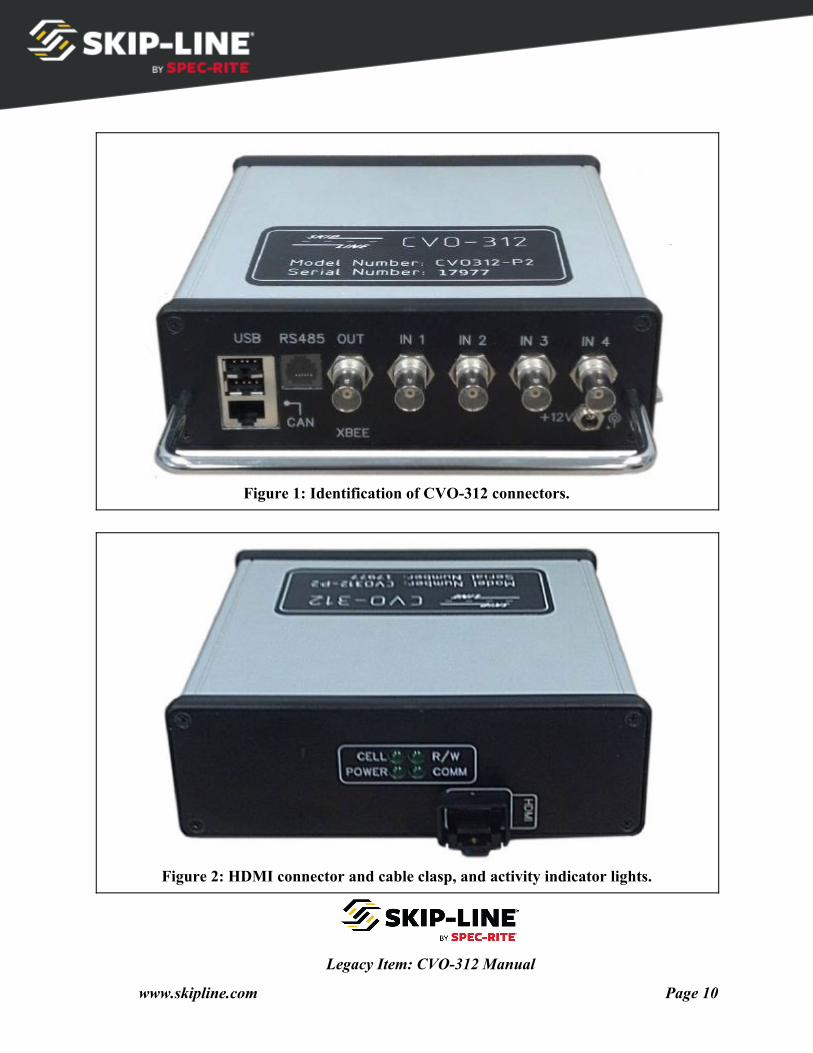
Figure 1: Identification of CVO-312 connectors.
Figure 2: HDMI connector and cable clasp, and activity indicator lights.
Legacy Item: CVO-312 Manual
www.skipline.com Page 10
3.1 Physical Installation After you have done the above preparations, then:
1. Attach the box to the mounting location. ● Use the flange mounting holes for a solid and permanent installation. ● Alternately, hook-and-loop (Velcro) fasteners may be used for temporary,
horizontal surface mounting. Do not ceiling mount with hook-and-loop fasteners 2. Connect a data source:
● For DL-08/09 data sources, connect the wireless antenna labeled “XBEE”. ● For an SM-5 (RS485) data source, connect a 6-conductor telephone cable to the
port labeled “RS485”. Connect the other end to a spare port on an SM-5 device. ● For an SC-12 (CAN) data source, connect a 6-conductor network cable to the port
labeled “CAN”. Connect the other end to a spare port on an SC-12 hub device. 3. Connect video cameras (NTSC) into the device using the BNC connectors labeled “IN 1”
through “IN 4”. ● If using a backup camera, connect it to “IN 4”.
4. Connect a video output cable. ● If using HDMI, use the port labeled “HDMI”. ● If using standard video (NTSC), use the BNC connector labeled “OUT”.
5. Connect the USB cable from the touch monitor to the CVO-312 USB port Once these steps have been completed, attach the power cable.
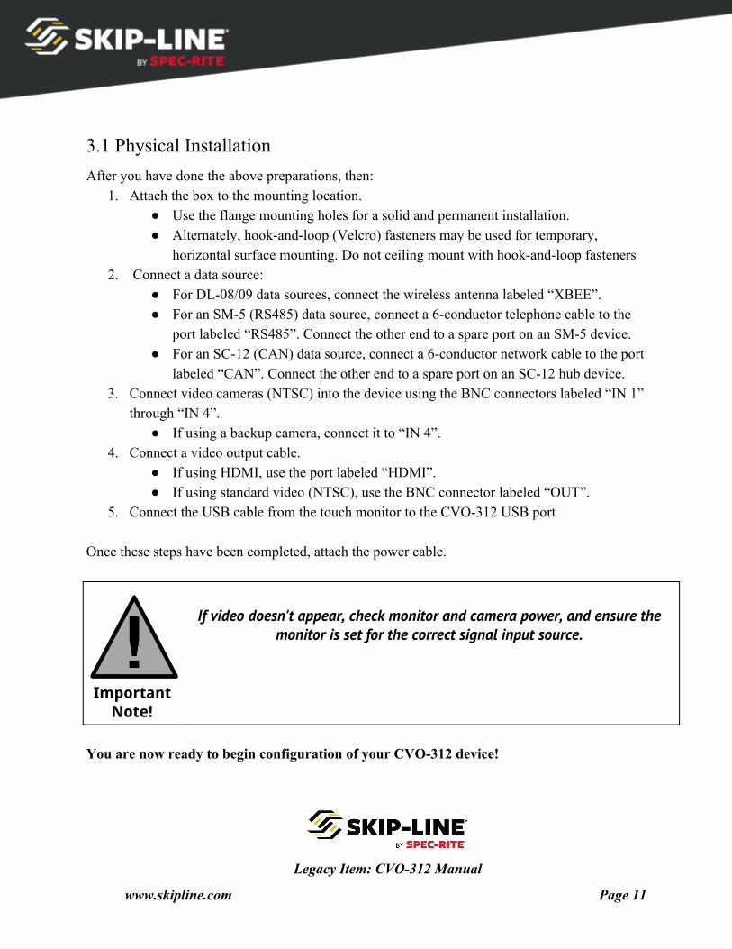
Important Note!
If video doesn't appear, check monitor and camera power, and ensure the monitor is set for the correct signal input source.
You are now ready to begin configuration of your CVO-312 device!
Legacy Item: CVO-312 Manual
www.skipline.com Page 11
3.2 DL-08/09 System Association When used with an SM-5 system (through the RS485 connector) or an SC- 12 system (through the CAN connector), this step is not necessary. For DL-08/09 data sources, the CVO-312 must be associated with the wireless network before data will be available and viewable on the screen. This process is described in the DL-08/09 manual. For your convenience, this section of the manual has been copied into this manual as Appendix A .
3.3 DL-08/09 Selection of Overlay Monitor Items
Important Note!
When used with an SM-5 system (through the RS485 connector) or an SC-12 system (through the CAN connector), this step is not necessary.
Follow instructions in section 4.2, “Main Screen Setup Menu”.
For DL-08/09 data sources, you must select monitor items to be transmitted from the
Skip-Line Data Logger laptop or tablet PC to the CVO-312. Any item that can be monitored on the data logger PC can be transmitted to the CVO-312. There are six video overlay item “slots” on the CVO-312 device. These six slots may be all used or none used. When unused, the slot will remain blank and transparent on the main screen. The process of selecting items to display is described in the DL-08/09 manual. For your convenience, this section of the manual has been copied into this manual as Appendix B.
3.4 Touch Calibration and Initial Setup This screen is typically not needed if your monitor was purchased with your CVO-312, as
your CVO-312 device was calibrated to your monitor at the factory. If this is the case, you should skip ahead to section 4.2.
Legacy Item: CVO-312 Manual
www.skipline.com Page 12
This section is relevant if:
● You purchased a monitor separately from your CVO-312. ● You are replacing your monitor. ● You are noticing issues using the touch screen where the software does not react in
alignment with the location of finger presses. ● You need to change the output from NTSC to HDMI. ● If any of the above apply to you, follow the instructions below to calibrate your touch
screen and perform basic device setup.
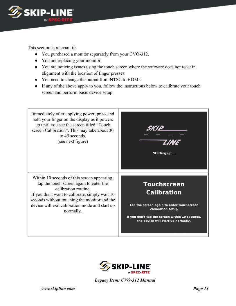
Immediately after applying power, press and hold your finger on the display as it powers
up until you see the screen titled “Touch screen Calibration”. This may take about 30
to 45 seconds. (see next figure)
Within 10 seconds of this screen appearing, tap the touch screen again to enter the
calibration routine. If you don't want to calibrate, simply wait 10 seconds without touching the monitor and the device will exit calibration mode and start up
normally.
Legacy Item: CVO-312 Manual
www.skipline.com Page 13
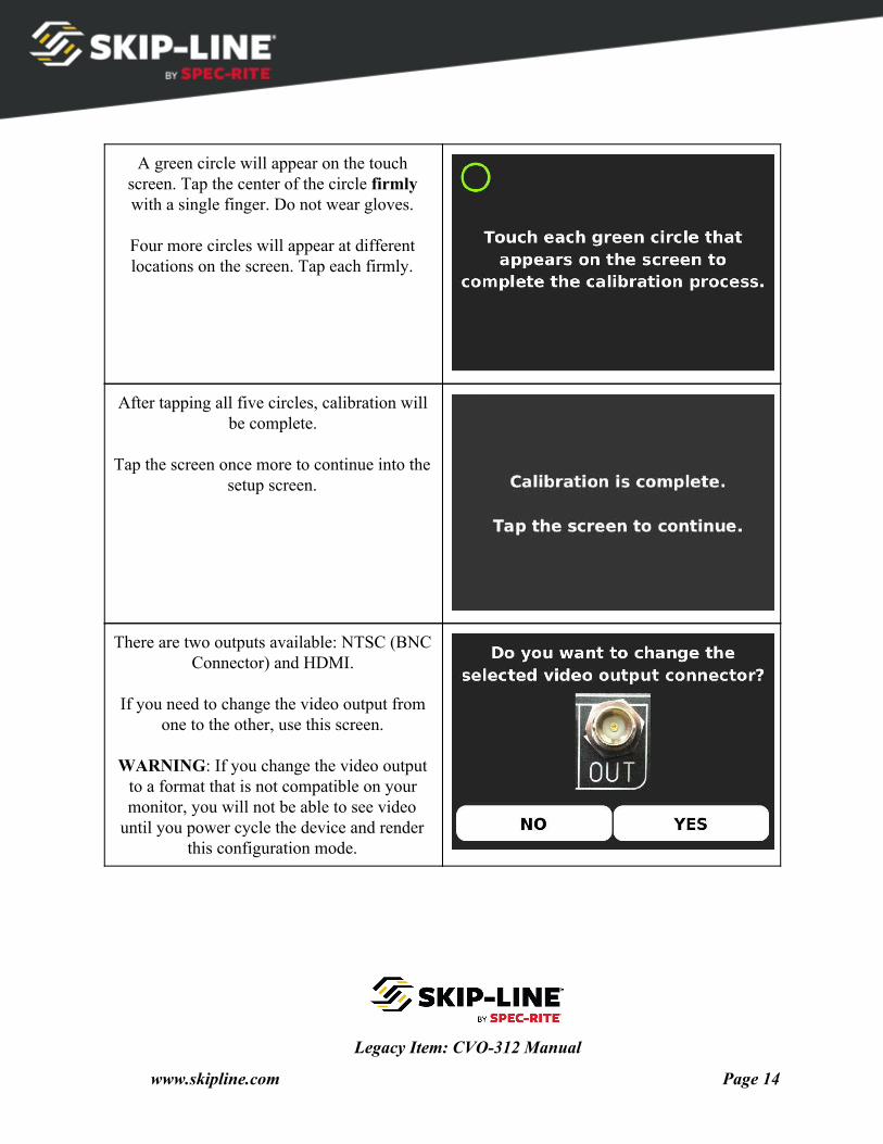
A green circle will appear on the touch screen. Tap the center of the circle firmly with a single finger. Do not wear gloves.
Four more circles will appear at different locations on the screen. Tap each firmly.
After tapping all five circles, calibration will be complete.
Tap the screen once more to continue into the
setup screen.
There are two outputs available: NTSC (BNC Connector) and HDMI.
If you need to change the video output from
one to the other, use this screen.
WARNING: If you change the video output to a format that is not compatible on your monitor, you will not be able to see video
until you power cycle the device and render this configuration mode.
Legacy Item: CVO-312 Manual
www.skipline.com Page 14
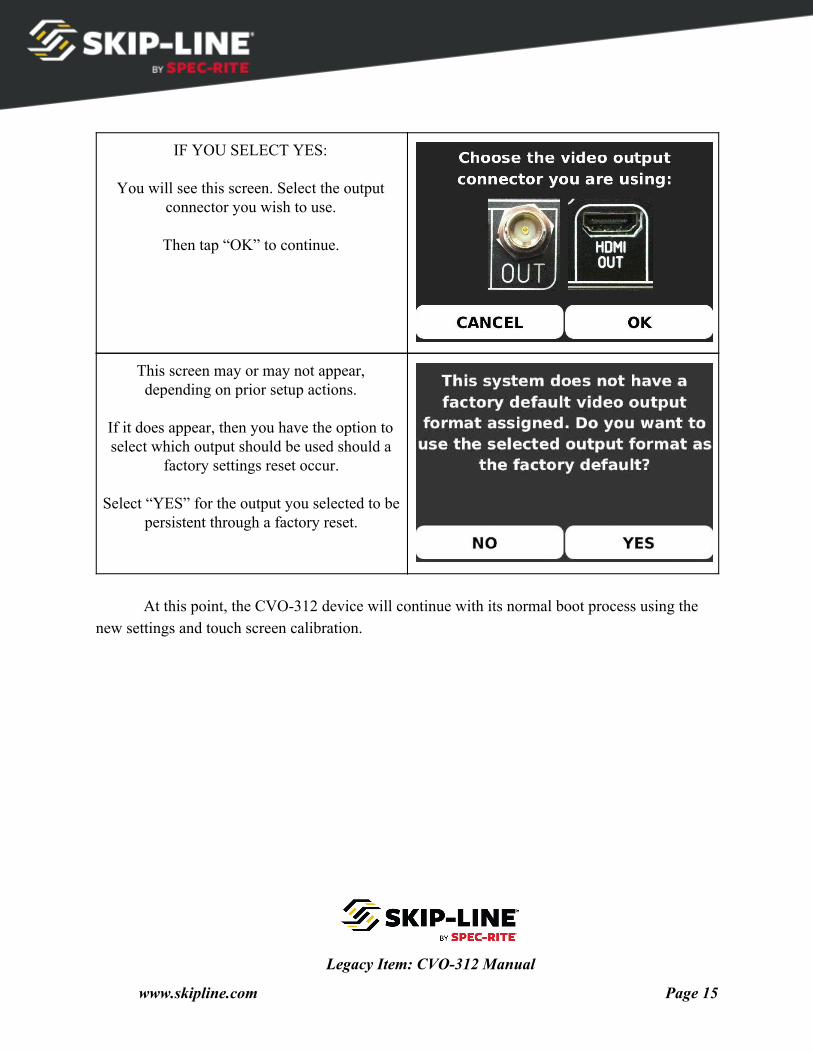
IF YOU SELECT YES:
You will see this screen. Select the output connector you wish to use.
Then tap “OK” to continue.
This screen may or may not appear, depending on prior setup actions.
If it does appear, then you have the option to select which output should be used should a
factory settings reset occur.
Select “YES” for the output you selected to be persistent through a factory reset.
At this point, the CVO-312 device will continue with its normal boot process using the
new settings and touch screen calibration.
Legacy Item: CVO-312 Manual
www.skipline.com Page 15
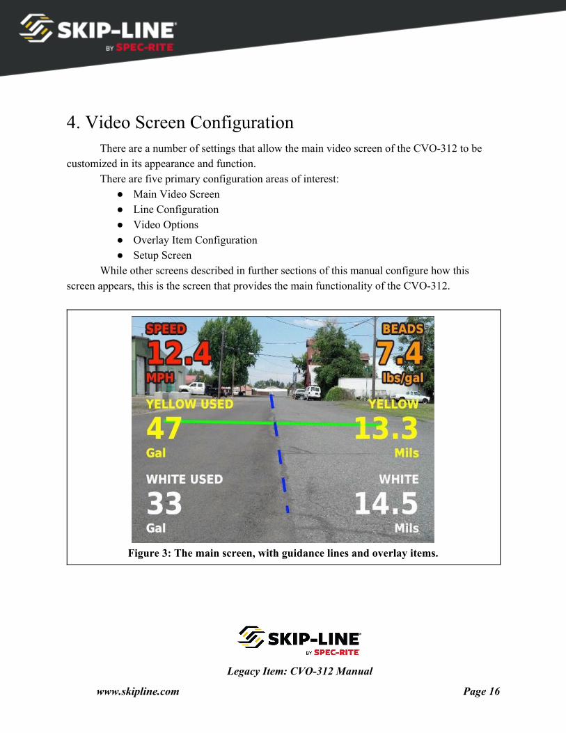
4. Video Screen Configuration There are a number of settings that allow the main video screen of the CVO-312 to be
customized in its appearance and function. There are five primary configuration areas of interest:
● Main Video Screen ● Line Configuration ● Video Options ● Overlay Item Configuration ● Setup Screen
While other screens described in further sections of this manual configure how this screen appears, this is the screen that provides the main functionality of the CVO-312.
Figure 3: The main screen, with guidance lines and overlay items.
Legacy Item: CVO-312 Manual
www.skipline.com Page 16
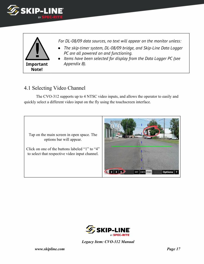
Important Note!
For DL-08/09 data sources, no text will appear on the monitor unless:
● The skip-timer system, DL-08/09 bridge, and Skip-Line Data Logger PC are all powered on and functioning.
● Items have been selected for display from the Data Logger PC (see Appendix B).
4.1 Selecting Video Channel The CVO-312 supports up to 4 NTSC video inputs, and allows the operator to easily and
quickly select a different video input on the fly using the touchscreen interface.
Tap on the main screen in open space. The options bar will appear.
Click on one of the buttons labeled “1” to “4” to select that respective video input channel.
Legacy Item: CVO-312 Manual
www.skipline.com Page 17
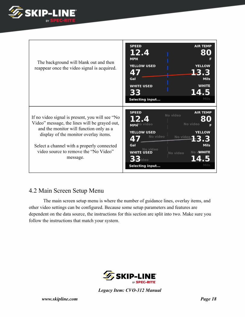
The background will blank out and then reappear once the video signal is acquired.
If no video signal is present, you will see “No Video” message, the lines will be grayed out,
and the monitor will function only as a display of the monitor overlay items.
Select a channel with a properly connected
video source to remove the “No Video” message.
4.2 Main Screen Setup Menu The main screen setup menu is where the number of guidance lines, overlay items, and
other video settings can be configured. Because some setup parameters and features are dependent on the data source, the instructions for this section are split into two. Make sure you follow the instructions that match your system.
Legacy Item: CVO-312 Manual
www.skipline.com Page 18
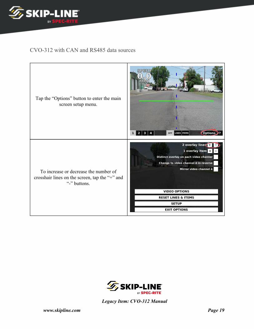
CVO-312 with CAN and RS485 data sources
Tap the “Options” button to enter the main screen setup menu.
To increase or decrease the number of crosshair lines on the screen, tap the “+” and
“-” buttons.
Legacy Item: CVO-312 Manual
www.skipline.com Page 19
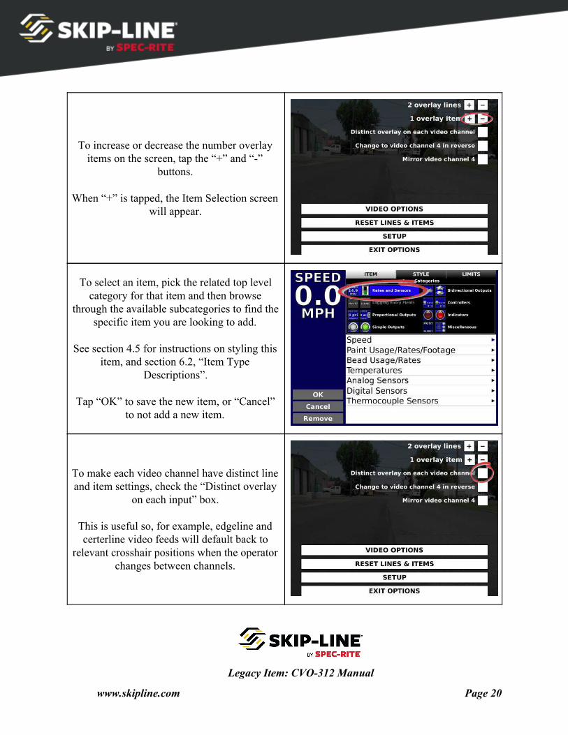
To increase or decrease the number overlay items on the screen, tap the “+” and “-”
buttons.
When “+” is tapped, the Item Selection screen will appear.
To select an item, pick the related top level category for that item and then browse
through the available subcategories to find the specific item you are looking to add.
See section 4.5 for instructions on styling this
item, and section 6.2, “Item Type Descriptions”.
Tap “OK” to save the new item, or “Cancel”
to not add a new item.
To make each video channel have distinct line and item settings, check the “Distinct overlay
on each input” box.
This is useful so, for example, edgeline and certerline video feeds will default back to
relevant crosshair positions when the operator changes between channels.
Legacy Item: CVO-312 Manual
www.skipline.com Page 20
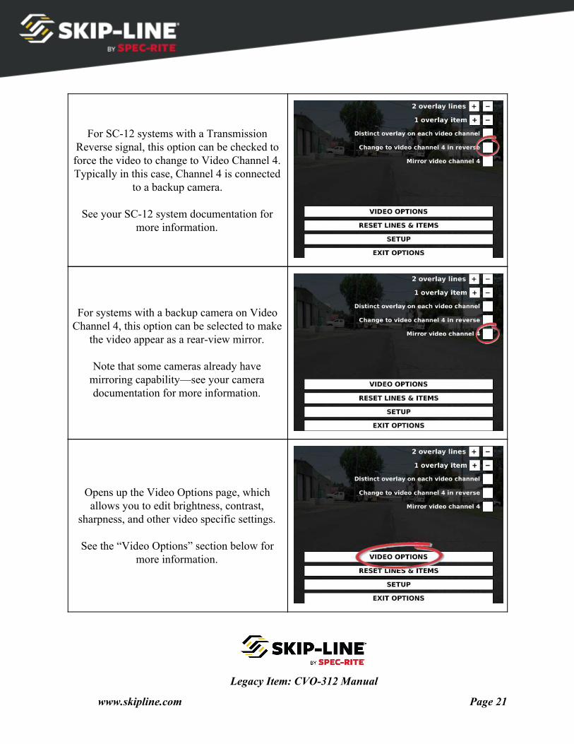
For SC-12 systems with a Transmission Reverse signal, this option can be checked to force the video to change to Video Channel 4. Typically in this case, Channel 4 is connected
to a backup camera.
See your SC-12 system documentation for more information.
For systems with a backup camera on Video Channel 4, this option can be selected to make
the video appear as a rear-view mirror.
Note that some cameras already have mirroring capability—see your camera documentation for more information.
Opens up the Video Options page, which allows you to edit brightness, contrast,
sharpness, and other video specific settings.
See the “Video Options” section below for more information.
Legacy Item: CVO-312 Manual
www.skipline.com Page 21
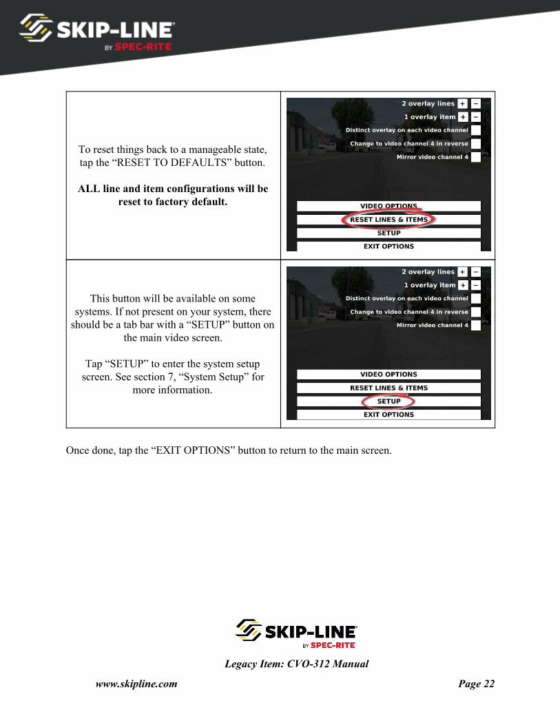
To reset things back to a manageable state, tap the “RESET TO DEFAULTS” button.
ALL line and item configurations will be
reset to factory default.
This button will be available on some systems. If not present on your system, there
should be a tab bar with a “SETUP” button on the main video screen.
Tap “SETUP” to enter the system setup
screen. See section 7, “System Setup” for more information.
Once done, tap the “EXIT OPTIONS” button to return to the main screen.
Legacy Item: CVO-312 Manual
www.skipline.com Page 22
CVO-312 with DL-08/09 data source
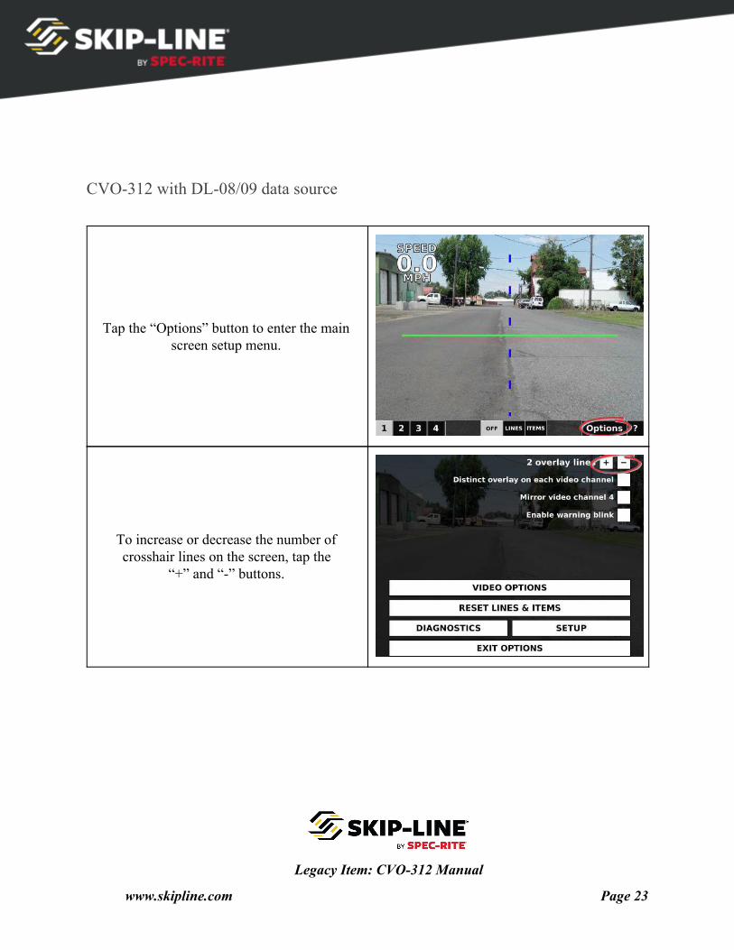
Tap the “Options” button to enter the main screen setup menu.
To increase or decrease the number of crosshair lines on the screen, tap the
“+” and “-” buttons.
Legacy Item: CVO-312 Manual
www.skipline.com Page 23
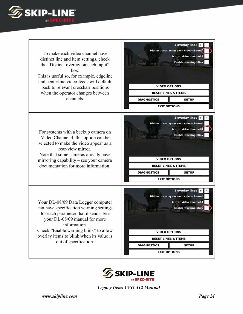
To make each video channel have distinct line and item settings, check the “Distinct overlay on each input”
box. This is useful so, for example, edgeline and centerline video feeds will default
back to relevant crosshair positions when the operator changes between
channels.
For systems with a backup camera on Video Channel 4, this option can be
selected to make the video appear as a rear-view mirror.
Note that some cameras already have mirroring capability – see your camera documentation for more information.
Your DL-08/09 Data Logger computer can have specification warning settings
for each parameter that it sends. See your DL-08/09 manual for more
information. Check “Enable warning blink” to allow overlay items to blink when its value is
out of specification.
Legacy Item: CVO-312 Manual
www.skipline.com Page 24
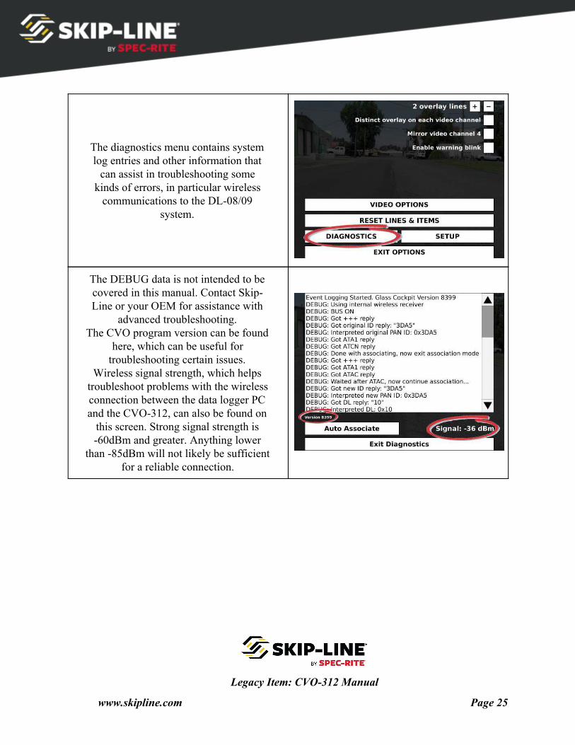
The diagnostics menu contains system log entries and other information that
can assist in troubleshooting some kinds of errors, in particular wireless
communications to the DL-08/09 system.
The DEBUG data is not intended to be covered in this manual. Contact Skip- Line or your OEM for assistance with
advanced troubleshooting. The CVO program version can be found
here, which can be useful for troubleshooting certain issues.
Wireless signal strength, which helps troubleshoot problems with the wireless connection between the data logger PC and the CVO-312, can also be found on
this screen. Strong signal strength is -60dBm and greater. Anything lower
than -85dBm will not likely be sufficient for a reliable connection.
Legacy Item: CVO-312 Manual
www.skipline.com Page 25
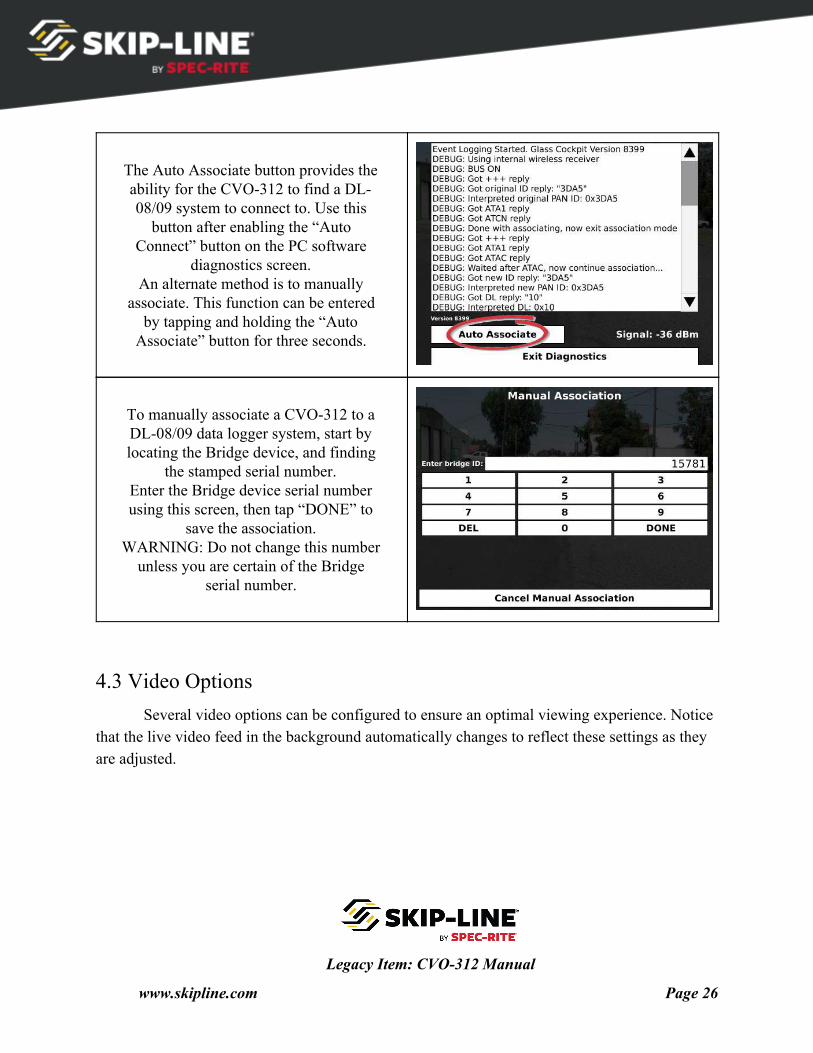
The Auto Associate button provides the ability for the CVO-312 to find a DL- 08/09 system to connect to. Use this
button after enabling the “Auto Connect” button on the PC software
diagnostics screen. An alternate method is to manually
associate. This function can be entered by tapping and holding the “Auto
Associate” button for three seconds.
To manually associate a CVO-312 to a DL-08/09 data logger system, start by locating the Bridge device, and finding
the stamped serial number. Enter the Bridge device serial number using this screen, then tap “DONE” to
save the association. WARNING: Do not change this number
unless you are certain of the Bridge serial number.
4.3 Video Options Several video options can be configured to ensure an optimal viewing experience. Notice
that the live video feed in the background automatically changes to reflect these settings as they are adjusted.
Legacy Item: CVO-312 Manual
www.skipline.com Page 26
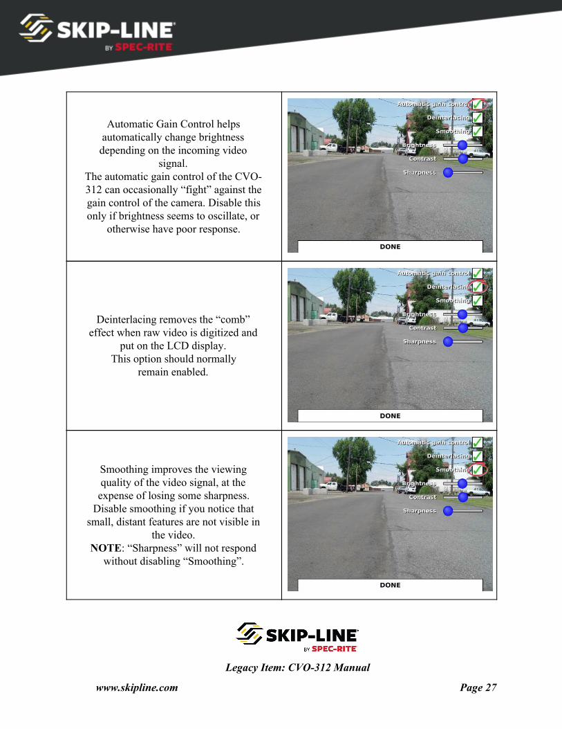
Automatic Gain Control helps automatically change brightness depending on the incoming video
signal. The automatic gain control of the CVO- 312 can occasionally “fight” against the gain control of the camera. Disable this only if brightness seems to oscillate, or
otherwise have poor response.
Deinterlacing removes the “comb” effect when raw video is digitized and
put on the LCD display. This option should normally
remain enabled.
Smoothing improves the viewing quality of the video signal, at the expense of losing some sharpness.
Disable smoothing if you notice that small, distant features are not visible in
the video. NOTE: “Sharpness” will not respond
without disabling “Smoothing”.
Legacy Item: CVO-312 Manual
www.skipline.com Page 27
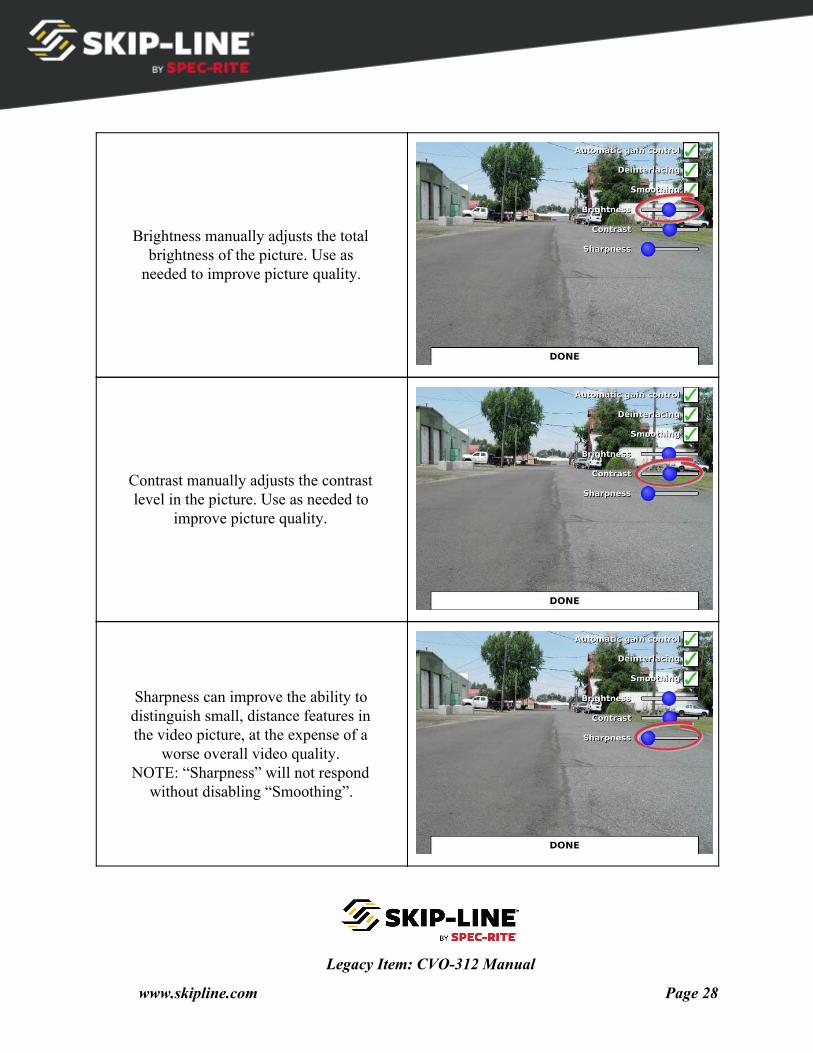
Brightness manually adjusts the total brightness of the picture. Use as
needed to improve picture quality.
Contrast manually adjusts the contrast level in the picture. Use as needed to
improve picture quality.
Sharpness can improve the ability to distinguish small, distance features in the video picture, at the expense of a
worse overall video quality. NOTE: “Sharpness” will not respond
without disabling “Smoothing”.
Legacy Item: CVO-312 Manual
www.skipline.com Page 28
Tap “DONE” after making changes to save the changes, and return to the
main setup menu.
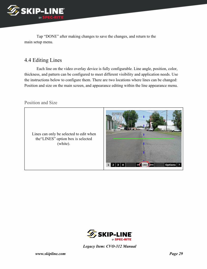
4.4 Editing Lines Each line on the video overlay device is fully configurable. Line angle, position, color,
thickness, and pattern can be configured to meet different visibility and application needs. Use the instructions below to configure them. There are two locations where lines can be changed: Position and size on the main screen, and appearance editing within the line appearance menu.
Position and Size
Lines can only be selected to edit when the“LINES” option box is selected
(white).
Legacy Item: CVO-312 Manual
www.skipline.com Page 29
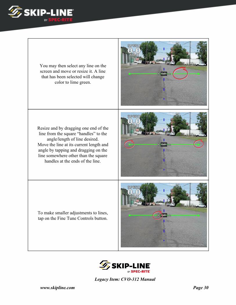
You may then select any line on the screen and move or resize it. A line that has been selected will change
color to lime green.
Resize and by dragging one end of the line from the square “handles” to the
angle/length of line desired. Move the line at its current length and angle by tapping and dragging on the line somewhere other than the square
handles at the ends of the line.
To make smaller adjustments to lines, tap on the Fine Tune Controls button.
Legacy Item: CVO-312 Manual
www.skipline.com Page 30
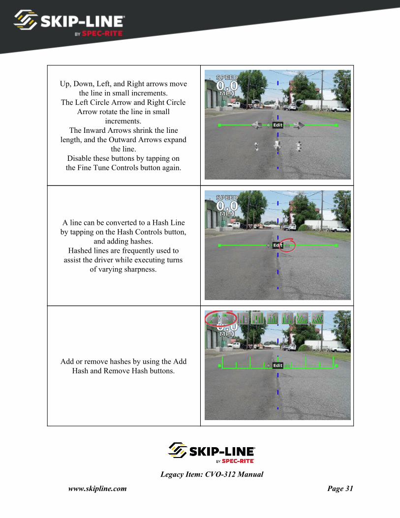
Up, Down, Left, and Right arrows move the line in small increments.
The Left Circle Arrow and Right Circle Arrow rotate the line in small
increments. The Inward Arrows shrink the line
length, and the Outward Arrows expand the line.
Disable these buttons by tapping on the Fine Tune Controls button again.
A line can be converted to a Hash Line by tapping on the Hash Controls button,
and adding hashes. Hashed lines are frequently used to
assist the driver while executing turns of varying sharpness.
Add or remove hashes by using the Add Hash and Remove Hash buttons.
Legacy Item: CVO-312 Manual
www.skipline.com Page 31
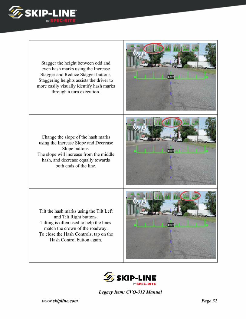
Stagger the height between odd and even hash marks using the Increase Stagger and Reduce Stagger buttons.
Staggering heights assists the driver to more easily visually identify hash marks
through a turn execution.
Change the slope of the hash marks using the Increase Slope and Decrease
Slope buttons. The slope will increase from the middle
hash, and decrease equally towards both ends of the line.
Tilt the hash marks using the Tilt Left and Tilt Right buttons.
Tilting is often used to help the lines match the crown of the roadway.
To close the Hash Controls, tap on the Hash Control button again.
Legacy Item: CVO-312 Manual
www.skipline.com Page 32
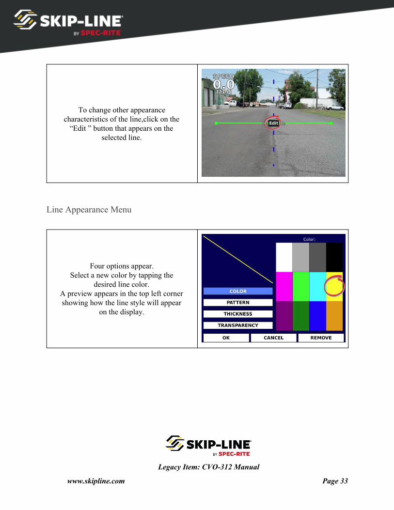
To change other appearance characteristics of the line,click on the
“Edit ” button that appears on the selected line.
Line Appearance Menu
Four options appear. Select a new color by tapping the
desired line color. A preview appears in the top left corner showing how the line style will appear
on the display.
Legacy Item: CVO-312 Manual
www.skipline.com Page 33
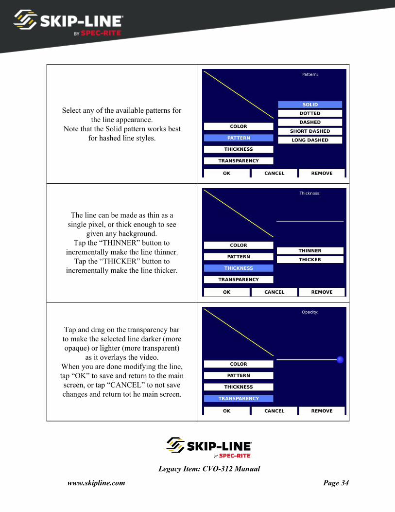
Select any of the available patterns for the line appearance.
Note that the Solid pattern works best for hashed line styles.
The line can be made as thin as a single pixel, or thick enough to see
given any background. Tap the “THINNER” button to
incrementally make the line thinner. Tap the “THICKER” button to
incrementally make the line thicker.
Tap and drag on the transparency bar to make the selected line darker (more opaque) or lighter (more transparent)
as it overlays the video. When you are done modifying the line, tap “OK” to save and return to the main screen, or tap “CANCEL” to not save changes and return tot he main screen.
Legacy Item: CVO-312 Manual
www.skipline.com Page 34
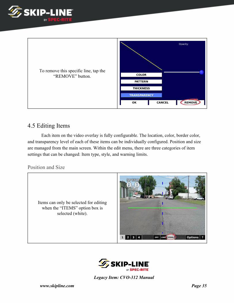
To remove this specific line, tap the “REMOVE” button.
4.5 Editing Items Each item on the video overlay is fully configurable. The location, color, border color,
and transparency level of each of these items can be individually configured. Position and size are managed from the main screen. Within the edit menu, there are three categories of item settings that can be changed: Item type, style, and warning limits.
Position and Size
Items can only be selected for editing when the “ITEMS” option box is
selected (white).
Legacy Item: CVO-312 Manual
www.skipline.com Page 35
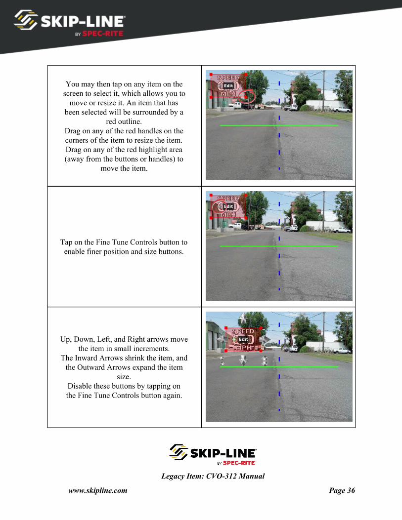
You may then tap on any item on the screen to select it, which allows you to
move or resize it. An item that has been selected will be surrounded by a
red outline. Drag on any of the red handles on the corners of the item to resize the item. Drag on any of the red highlight area (away from the buttons or handles) to
move the item.
Tap on the Fine Tune Controls button to enable finer position and size buttons.
Up, Down, Left, and Right arrows move the item in small increments.
The Inward Arrows shrink the item, and the Outward Arrows expand the item
size. Disable these buttons by tapping on the Fine Tune Controls button again.
Legacy Item: CVO-312 Manual
www.skipline.com Page 36
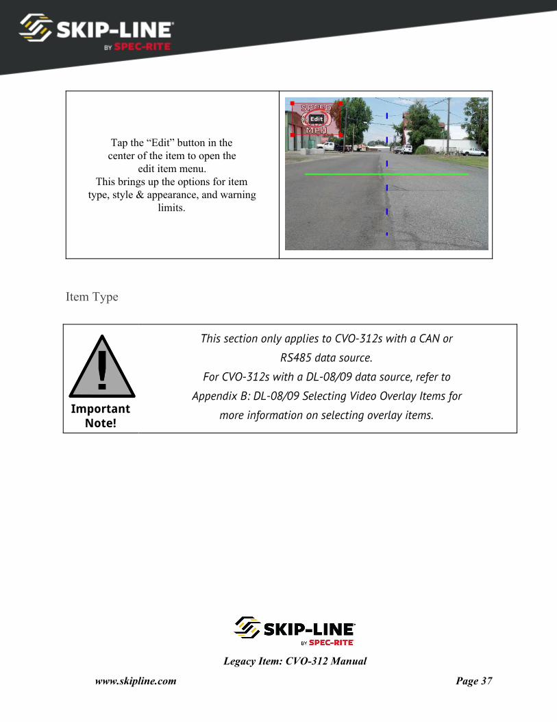
Tap the “Edit” button in the center of the item to open the
edit item menu. This brings up the options for item
type, style & appearance, and warning limits.
Item Type
Important Note!
This section only applies to CVO-312s with a CAN or
RS485 data source.
For CVO-312s with a DL-08/09 data source, refer to
Appendix B: DL-08/09 Selecting Video Overlay Items for
more information on selecting overlay items.
Legacy Item: CVO-312 Manual
www.skipline.com Page 37
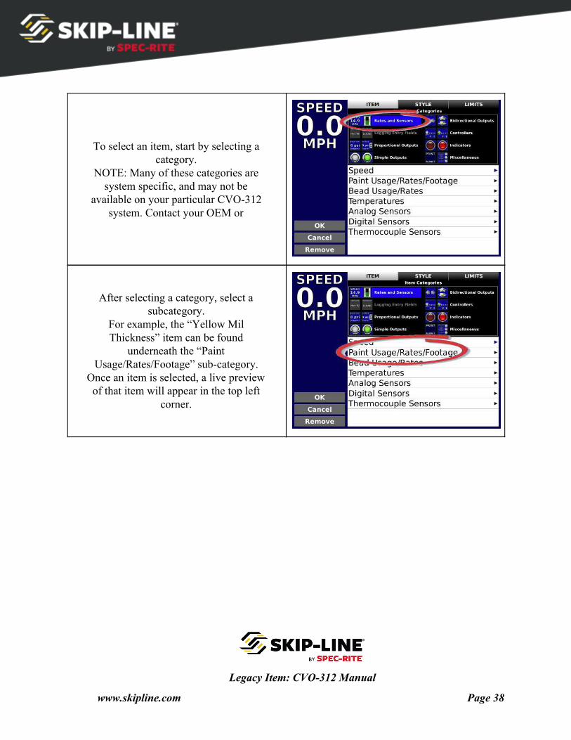
To select an item, start by selecting a category.
NOTE: Many of these categories are system specific, and may not be
available on your particular CVO-312 system. Contact your OEM or
After selecting a category, select a subcategory.
For example, the “Yellow Mil Thickness” item can be found
underneath the “Paint Usage/Rates/Footage” sub-category.
Once an item is selected, a live preview of that item will appear in the top left
corner.
Legacy Item: CVO-312 Manual
www.skipline.com Page 38
Style
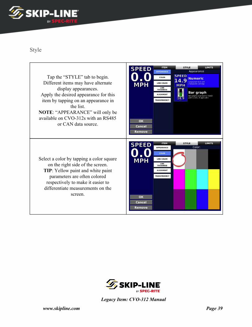
Tap the “STYLE” tab to begin. Different items may have alternate
display appearances. Apply the desired appearance for this item by tapping on an appearance in
the list. NOTE: “APPEARANCE” will only be available on CVO-312s with an RS485
or CAN data source.
Select a color by tapping a color square on the right side of the screen.
TIP: Yellow paint and white paint parameters are often colored
respectively to make it easier to differentiate measurements on the
screen.
Legacy Item: CVO-312 Manual
www.skipline.com Page 39
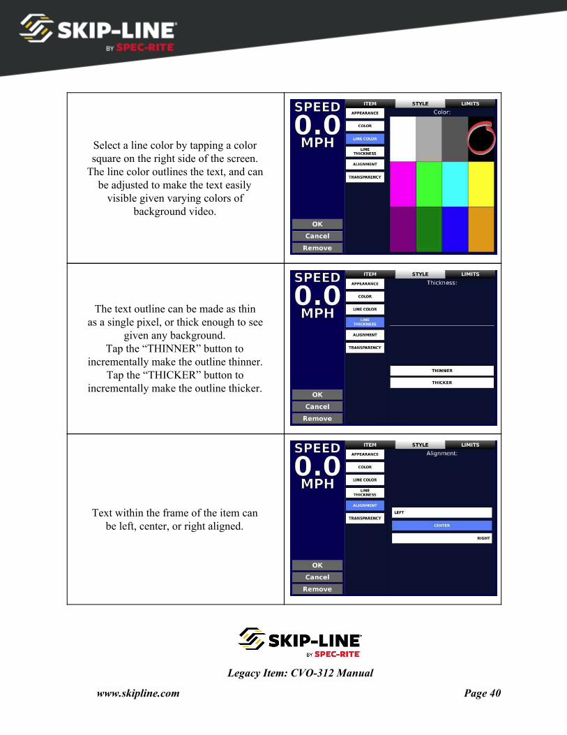
Select a line color by tapping a color square on the right side of the screen.
The line color outlines the text, and can be adjusted to make the text easily
visible given varying colors of background video.
The text outline can be made as thin as a single pixel, or thick enough to see
given any background. Tap the “THINNER” button to
incrementally make the outline thinner. Tap the “THICKER” button to
incrementally make the outline thicker.
Text within the frame of the item can be left, center, or right aligned.
Legacy Item: CVO-312 Manual
www.skipline.com Page 40
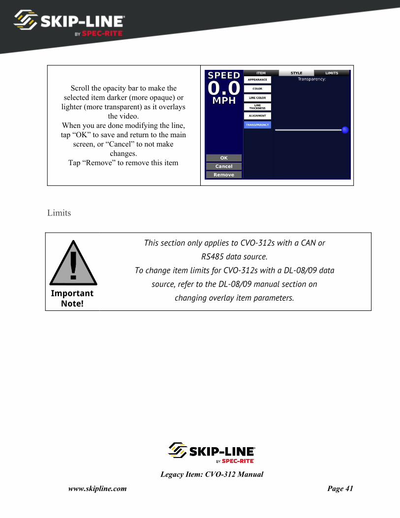
Scroll the opacity bar to make the selected item darker (more opaque) or
lighter (more transparent) as it overlays the video.
When you are done modifying the line, tap “OK” to save and return to the main
screen, or “Cancel” to not make changes.
Tap “Remove” to remove this item
Limits
Important Note!
This section only applies to CVO-312s with a CAN or
RS485 data source.
To change item limits for CVO-312s with a DL-08/09 data
source, refer to the DL-08/09 manual section on
changing overlay item parameters.
Legacy Item: CVO-312 Manual
www.skipline.com Page 41
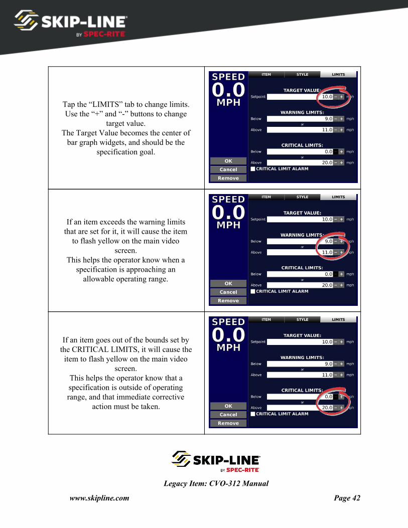
Tap the “LIMITS” tab to change limits. Use the “+” and “-” buttons to change
target value. The Target Value becomes the center of
bar graph widgets, and should be the specification goal.
If an item exceeds the warning limits that are set for it, it will cause the item
to flash yellow on the main video screen.
This helps the operator know when a specification is approaching an
allowable operating range.
If an item goes out of the bounds set by the CRITICAL LIMITS, it will cause the item to flash yellow on the main video
screen. This helps the operator know that a specification is outside of operating range, and that immediate corrective
action must be taken.
Legacy Item: CVO-312 Manual
www.skipline.com Page 42
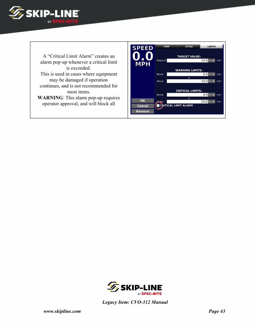
A “Critical Limit Alarm” creates an alarm pop-up whenever a critical limit
is exceeded. This is used in cases where equipment
may be damaged if operation continues, and is not recommended for
most items. WARNING: This alarm pop-up requires
operator approval, and will block all
Legacy Item: CVO-312 Manual
www.skipline.com Page 43
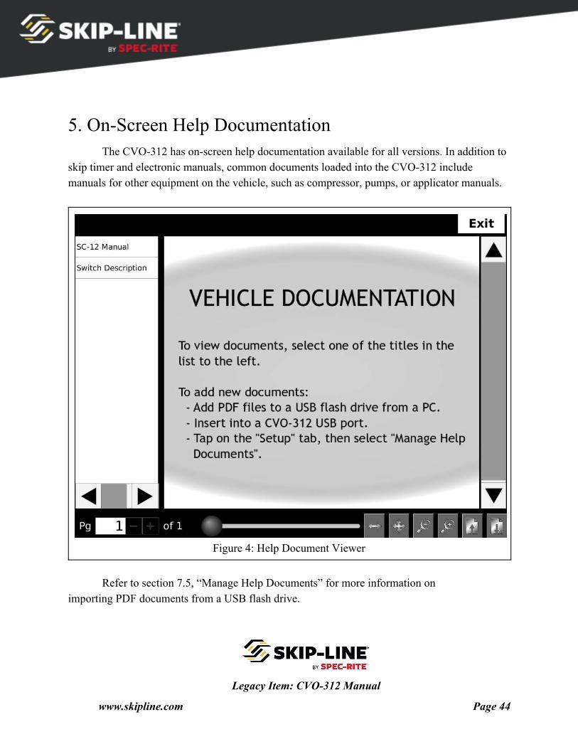
5. On-Screen Help Documentation The CVO-312 has on-screen help documentation available for all versions. In addition to
skip timer and electronic manuals, common documents loaded into the CVO-312 include manuals for other equipment on the vehicle, such as compressor, pumps, or applicator manuals.
Figure 4: Help Document Viewer
Refer to section 7.5, “Manage Help Documents” for more information on
importing PDF documents from a USB flash drive.
Legacy Item: CVO-312 Manual
www.skipline.com Page 44
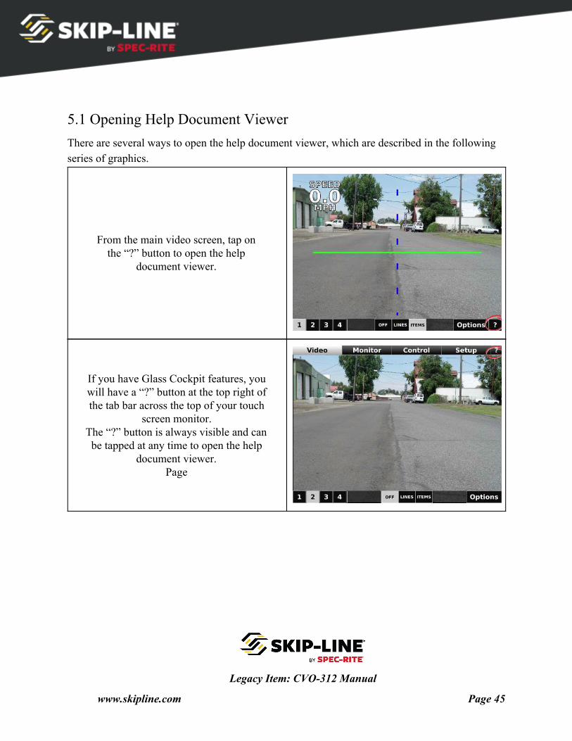
5.1 Opening Help Document Viewer There are several ways to open the help document viewer, which are described in the following series of graphics.
From the main video screen, tap on the “?” button to open the help
document viewer.
If you have Glass Cockpit features, you will have a “?” button at the top right of the tab bar across the top of your touch
screen monitor. The “?” button is always visible and can be tapped at any time to open the help
document viewer. Page
Legacy Item: CVO-312 Manual
www.skipline.com Page 45
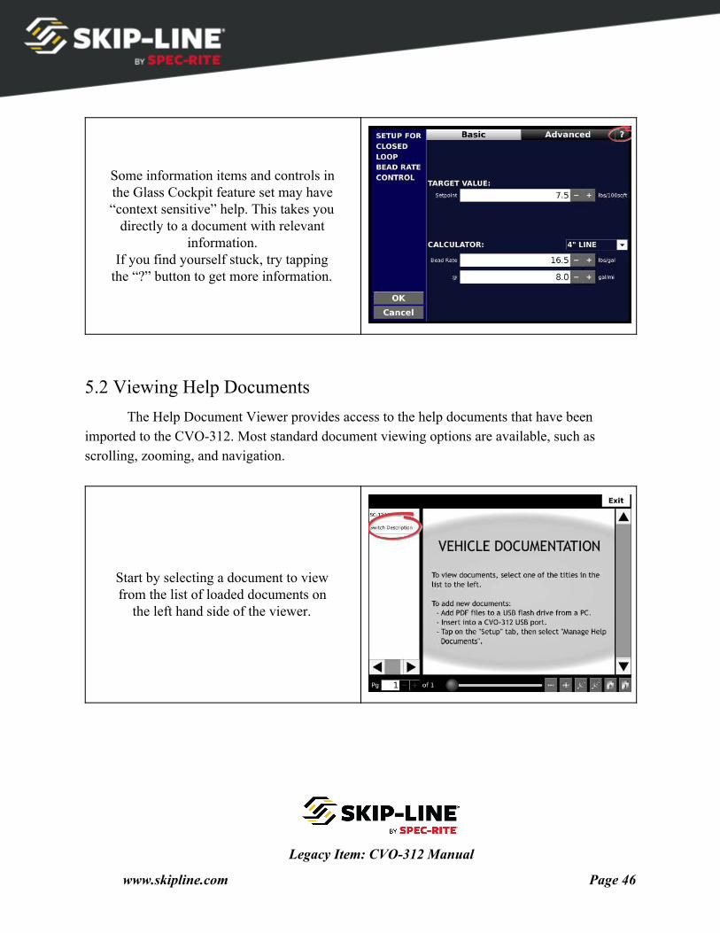
Some information items and controls in the Glass Cockpit feature set may have “context sensitive” help. This takes you
directly to a document with relevant information.
If you find yourself stuck, try tapping the “?” button to get more information.
5.2 Viewing Help Documents The Help Document Viewer provides access to the help documents that have been
imported to the CVO-312. Most standard document viewing options are available, such as scrolling, zooming, and navigation.
Start by selecting a document to view from the list of loaded documents on
the left hand side of the viewer.
Legacy Item: CVO-312 Manual
www.skipline.com Page 46
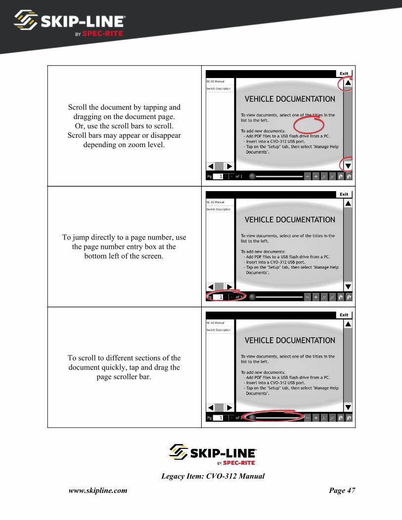
Scroll the document by tapping and dragging on the document page. Or, use the scroll bars to scroll.
Scroll bars may appear or disappear depending on zoom level.
To jump directly to a page number, use the page number entry box at the
bottom left of the screen.
To scroll to different sections of the document quickly, tap and drag the
page scroller bar.
Legacy Item: CVO-312 Manual
www.skipline.com Page 47
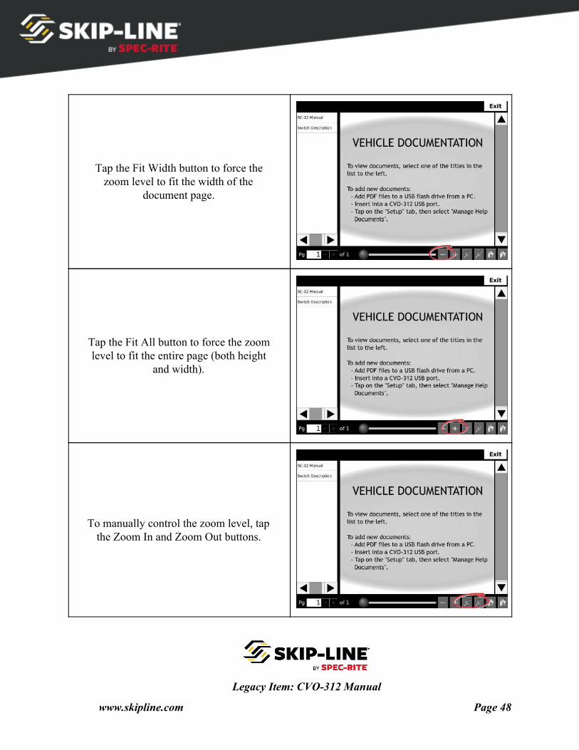
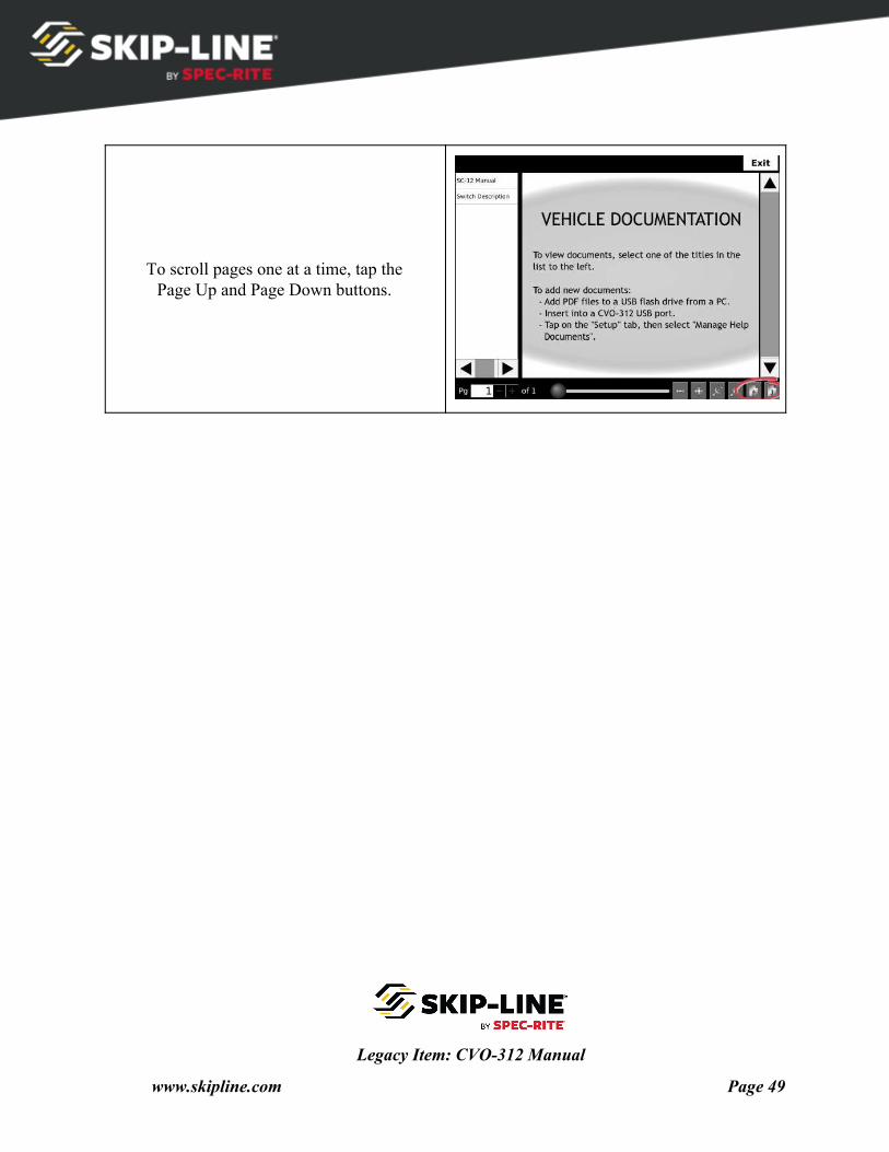
Tap the Fit Width button to force the zoom level to fit the width of the
document page.
Tap the Fit All button to force the zoom level to fit the entire page (both height
and width).
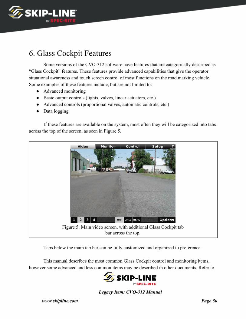
To manually control the zoom level, tap the Zoom In and Zoom Out buttons.
Legacy Item: CVO-312 Manual
www.skipline.com Page 48
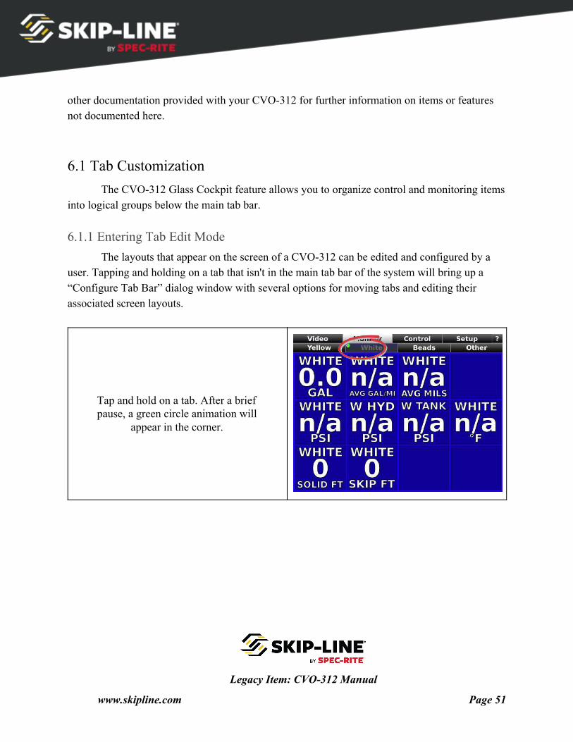
To scroll pages one at a time, tap the Page Up and Page Down buttons.
Legacy Item: CVO-312 Manual
www.skipline.com Page 49
6. Glass Cockpit Features Some versions of the CVO-312 software have features that are categorically described as
“Glass Cockpit” features. These features provide advanced capabilities that give the operator situational awareness and touch screen control of most functions on the road marking vehicle. Some examples of these features include, but are not limited to:
● Advanced monitoring ● Basic output controls (lights, valves, linear actuators, etc.) ● Advanced controls (proportional valves, automatic controls, etc.) ● Data logging
If these features are available on the system, most often they will be categorized into tabs
across the top of the screen, as seen in Figure 5.
Figure 5: Main video screen, with additional Glass Cockpit tab
bar across the top.
Tabs below the main tab bar can be fully customized and organized to preference. This manual describes the most common Glass Cockpit control and monitoring items,
however some advanced and less common items may be described in other documents. Refer to
Legacy Item: CVO-312 Manual
www.skipline.com Page 50
other documentation provided with your CVO-312 for further information on items or features not documented here.
6.1 Tab Customization The CVO-312 Glass Cockpit feature allows you to organize control and monitoring items
into logical groups below the main tab bar.
6.1.1 Entering Tab Edit Mode The layouts that appear on the screen of a CVO-312 can be edited and configured by a
user. Tapping and holding on a tab that isn't in the main tab bar of the system will bring up a “Configure Tab Bar” dialog window with several options for moving tabs and editing their associated screen layouts.
Tap and hold on a tab. After a brief pause, a green circle animation will
appear in the corner.
Legacy Item: CVO-312 Manual
www.skipline.com Page 51
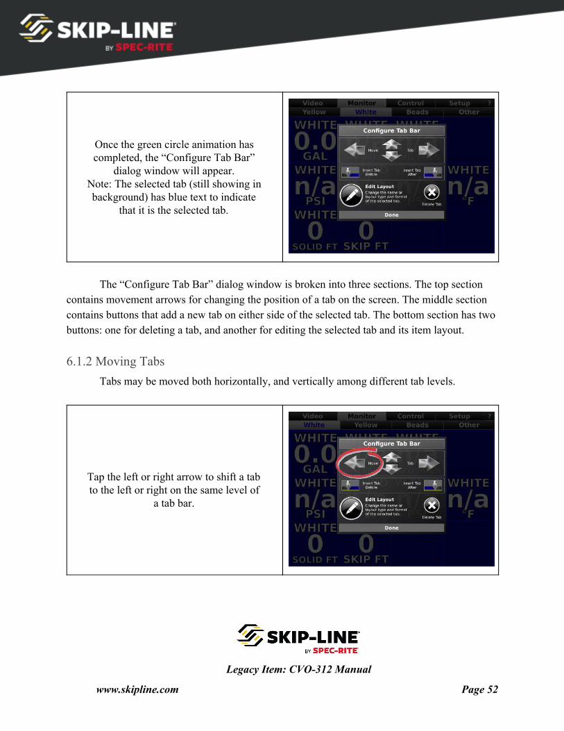
Once the green circle animation has completed, the “Configure Tab Bar”
dialog window will appear. Note: The selected tab (still showing in background) has blue text to indicate
that it is the selected tab.
The “Configure Tab Bar” dialog window is broken into three sections. The top section
contains movement arrows for changing the position of a tab on the screen. The middle section contains buttons that add a new tab on either side of the selected tab. The bottom section has two buttons: one for deleting a tab, and another for editing the selected tab and its item layout.
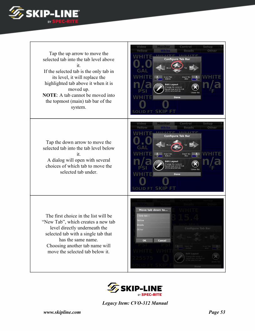
6.1.2 Moving Tabs Tabs may be moved both horizontally, and vertically among different tab levels.
Tap the left or right arrow to shift a tab to the left or right on the same level of
a tab bar.
Legacy Item: CVO-312 Manual
www.skipline.com Page 52
Tap the up arrow to move the selected tab into the tab level above
it. If the selected tab is the only tab in
its level, it will replace the highlighted tab above it when it is
moved up. NOTE: A tab cannot be moved into
the topmost (main) tab bar of the system.
Tap the down arrow to move the selected tab into the tab level below
it. A dialog will open with several
choices of which tab to move the selected tab under.
The first choice in the list will be “New Tab”, which creates a new tab
level directly underneath the selected tab with a single tab that
has the same name. Choosing another tab name will move the selected tab below it.
Legacy Item: CVO-312 Manual
www.skipline.com Page 53
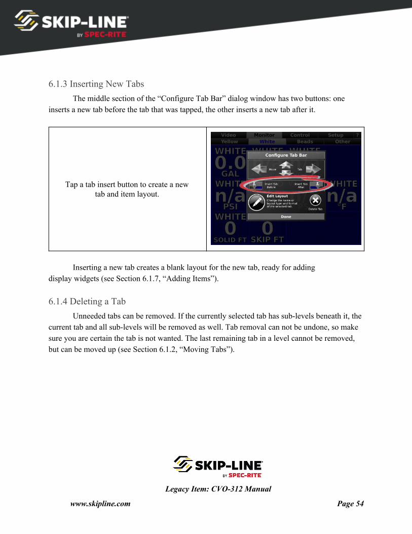
6.1.3 Inserting New Tabs The middle section of the “Configure Tab Bar” dialog window has two buttons: one
inserts a new tab before the tab that was tapped, the other inserts a new tab after it.
Tap a tab insert button to create a new tab and item layout.
Inserting a new tab creates a blank layout for the new tab, ready for adding
display widgets (see Section 6.1.7, “Adding Items”).
6.1.4 Deleting a Tab Unneeded tabs can be removed. If the currently selected tab has sub-levels beneath it, the
current tab and all sub-levels will be removed as well. Tab removal can not be undone, so make sure you are certain the tab is not wanted. The last remaining tab in a level cannot be removed, but can be moved up (see Section 6.1.2, “Moving Tabs”).
Legacy Item: CVO-312 Manual
www.skipline.com Page 54
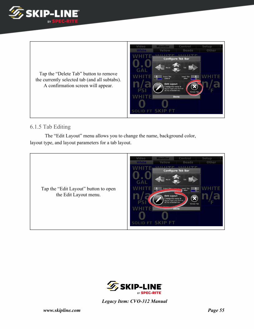
Tap the “Delete Tab” button to remove the currently selected tab (and all subtabs).
A confirmation screen will appear.
6.1.5 Tab Editing The “Edit Layout” menu allows you to change the name, background color,
layout type, and layout parameters for a tab layout.
Tap the “Edit Layout” button to open the Edit Layout menu.
Legacy Item: CVO-312 Manual
www.skipline.com Page 55
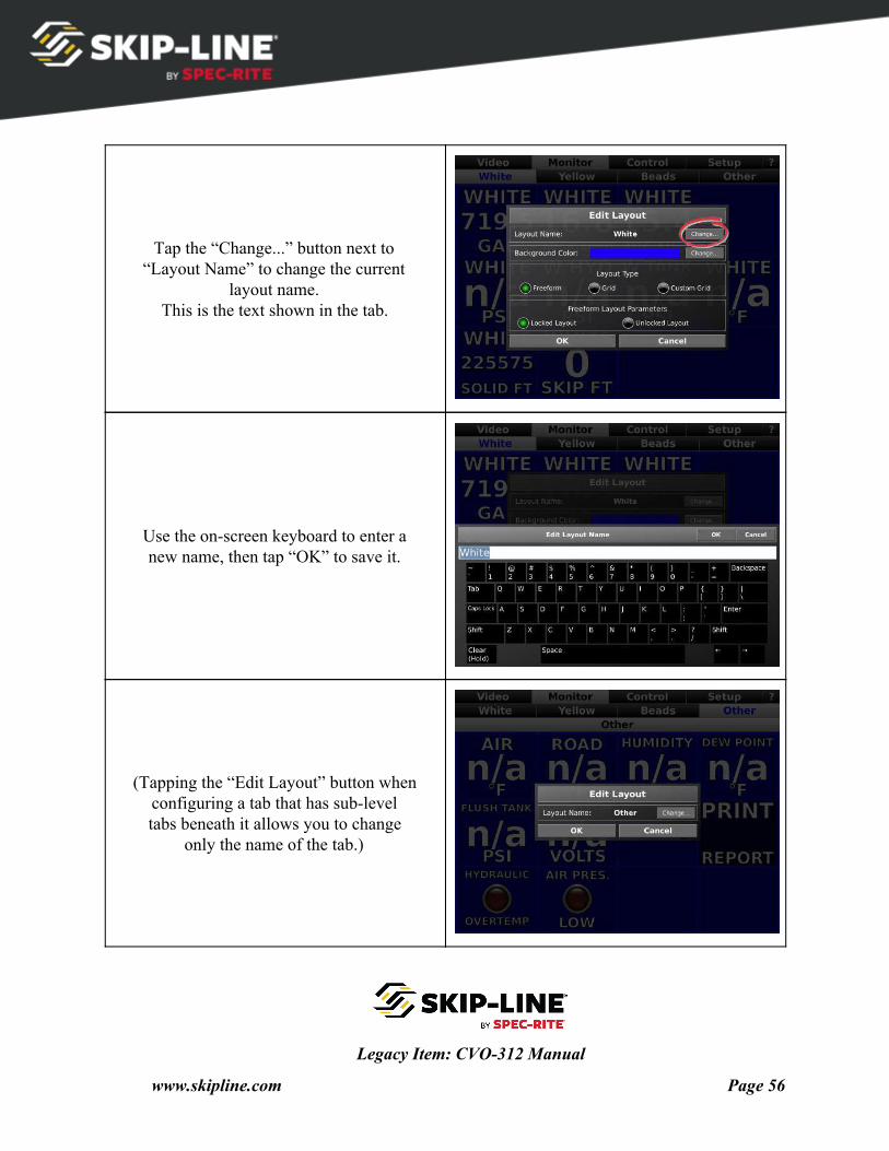
Tap the “Change...” button next to “Layout Name” to change the current
layout name. This is the text shown in the tab.
Use the on-screen keyboard to enter a new name, then tap “OK” to save it.
(Tapping the “Edit Layout” button when configuring a tab that has sub-level tabs beneath it allows you to change
only the name of the tab.)
Legacy Item: CVO-312 Manual
www.skipline.com Page 56
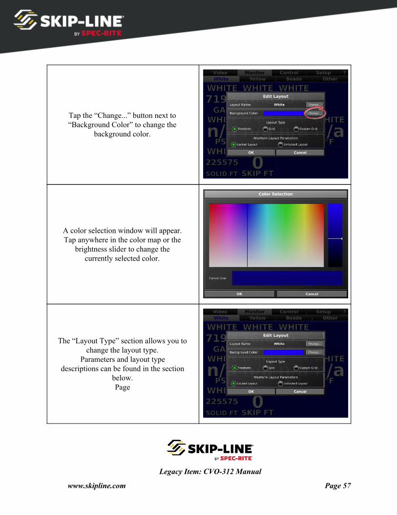
Tap the “Change...” button next to “Background Color” to change the
background color.
A color selection window will appear. Tap anywhere in the color map or the
brightness slider to change the currently selected color.
The “Layout Type” section allows you to change the layout type.
Parameters and layout type descriptions can be found in the section
below. Page
Legacy Item: CVO-312 Manual
www.skipline.com Page 57
6.1.6 Layout Types Choosing between the different layout types in the “Edit Layout” window will convert
the existing screen layout from its old type to the selected type once the “OK” button is tapped. The conversion processes will generally try to preserve the old screen layout, but may rearrange some displayed items. Layout types include freeform, grid, and custom grid.
Freeform Layouts
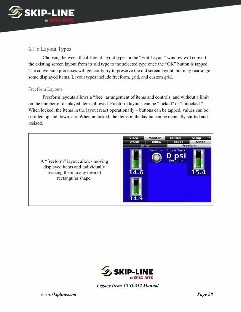
Freeform layouts allows a “free” arrangement of items and controls, and without a limit on the number of displayed items allowed. Freeform layouts can be “locked” or “unlocked.” When locked, the items in the layout react operationally – buttons can be tapped, values can be scrolled up and down, etc. When unlocked, the items in the layout can be manually shifted and resized.
A “freeform” layout allows moving displayed items and individually
resizing them to any desired rectangular shape.
Legacy Item: CVO-312 Manual
www.skipline.com Page 58
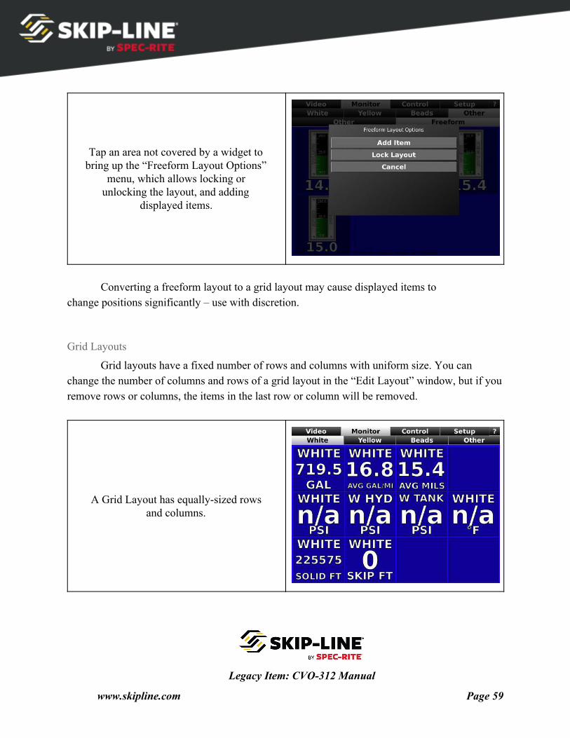
Tap an area not covered by a widget to bring up the “Freeform Layout Options”
menu, which allows locking or unlocking the layout, and adding
displayed items.
Converting a freeform layout to a grid layout may cause displayed items to
change positions significantly – use with discretion.
Grid Layouts
Grid layouts have a fixed number of rows and columns with uniform size. You can change the number of columns and rows of a grid layout in the “Edit Layout” window, but if you remove rows or columns, the items in the last row or column will be removed.
A Grid Layout has equally-sized rows and columns.
Legacy Item: CVO-312 Manual
www.skipline.com Page 59
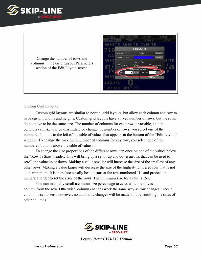
Change the number of rows and columns in the Grid Layout Parameters
section of the Edit Layout screen.
Custom Grid Layouts
Custom grid layouts are similar to normal grid layouts, but allow each column and row to have custom widths and heights. Custom grid layouts have a fixed number of rows, but the rows do not have to be the same size. The number of columns for each row is variable, and the columns can likewise be dissimilar. To change the number of rows, you select one of the numbered buttons to the left of the table of values that appears at the bottom of the “Edit Layout” window. To change the maximum number of columns for any row, you select one of the numbered buttons above the table of values.
To change the size proportions of the different rows, tap once on one of the values below the “Row % Size” header. This will bring up a set of up and down arrows that can be used to scroll the value up or down. Making a value smaller will increase the size of the smallest of any other rows. Making a value larger will decrease the size of the highest-numbered row that is not at its minimum. It is therefore usually best to start at the row numbered “1” and proceed in numerical order to set the sizes of the rows. The minimum size for a row is 15%.
You can manually scroll a column size percentage to zero, which removes a column from the row. Otherwise, column changes work the same way as row changes. Once a column is set to zero, however, no automatic changes will be made to it by scrolling the sizes of other columns.
Legacy Item: CVO-312 Manual
www.skipline.com Page 60
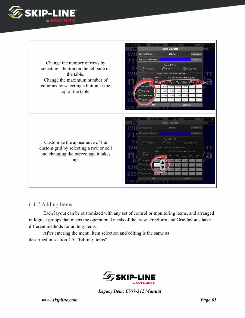
Change the number of rows by selecting a button on the left side of
the table. Change the maximum number of
columns by selecting a button at the top of the table.
Customize the appearance of the custom grid by selecting a row or cell and changing the percentage it takes
up.
6.1.7 Adding Items Each layout can be customized with any set of control or monitoring items, and arranged
in logical groups that meets the operational needs of the crew. Freeform and Grid layouts have different methods for adding items.
After entering the menu, item selection and editing is the same as described in section 4.5, “Editing Items”.
Legacy Item: CVO-312 Manual
www.skipline.com Page 61
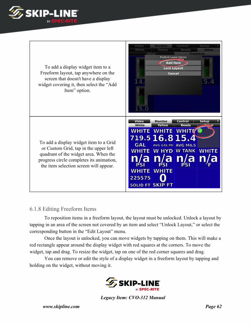
To add a display widget item to a Freeform layout, tap anywhere on the
screen that doesn't have a display widget covering it, then select the “Add
Item” option.
To add a display widget item to a Grid or Custom Grid, tap in the upper left
quadrant of the widget area. When the progress circle completes its animation, the item selection screen will appear.
6.1.8 Editing Freeform Items To reposition items in a freeform layout, the layout must be unlocked. Unlock a layout by
tapping in an area of the screen not covered by an item and select “Unlock Layout,” or select the corresponding button in the “Edit Layout” menu.
Once the layout is unlocked, you can move widgets by tapping on them. This will make a red rectangle appear around the display widget with red squares at the corners. To move the widget, tap and drag. To resize the widget, tap on one of the red corner squares and drag.
You can remove or edit the style of a display widget in a freeform layout by tapping and holding on the widget, without moving it.
Legacy Item: CVO-312 Manual
www.skipline.com Page 62
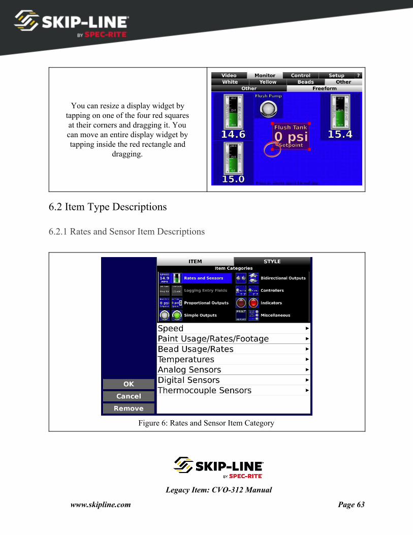
You can resize a display widget by tapping on one of the four red squares at their corners and dragging it. You can move an entire display widget by tapping inside the red rectangle and
dragging.
6.2 Item Type Descriptions
6.2.1 Rates and Sensor Item Descriptions
Figure 6: Rates and Sensor Item Category
Legacy Item: CVO-312 Manual
www.skipline.com Page 63
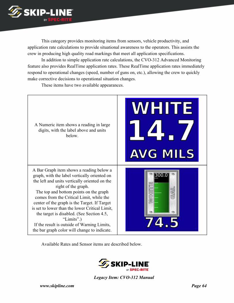
This category provides monitoring items from sensors, vehicle productivity, and
application rate calculations to provide situational awareness to the operators. This assists the crew in producing high quality road markings that meet all application specifications.
In addition to simple application rate calculations, the CVO-312 Advanced Monitoring feature also provides RealTime application rates. These RealTime application rates immediately respond to operational changes (speed, number of guns on, etc.), allowing the crew to quickly make corrective decisions to operational situation changes.
These items have two available appearances.
A Numeric item shows a reading in large digits, with the label above and units
below.
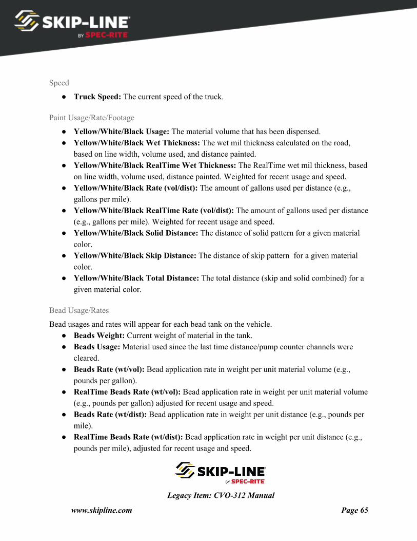
A Bar Graph item shows a reading below a graph, with the label vertically oriented on the left and units vertically oriented on the
right of the graph. The top and bottom points on the graph comes from the Critical Limit, while the
center of the graph is the Target. If Target is set to lower than the lower Critical Limit,
the target is disabled. (See Section 4.5, “Limits”.)
If the result is outside of Warning Limits, the bar graph color will change to indicate.
Available Rates and Sensor items are described below.
Legacy Item: CVO-312 Manual
www.skipline.com Page 64
Speed
● Truck Speed: The current speed of the truck.
Paint Usage/Rate/Footage
● Yellow/White/Black Usage: The material volume that has been dispensed. ● Yellow/White/Black Wet Thickness: The wet mil thickness calculated on the road,
based on line width, volume used, and distance painted. ● Yellow/White/Black RealTime Wet Thickness: The RealTime wet mil thickness, based
on line width, volume used, distance painted. Weighted for recent usage and speed. ● Yellow/White/Black Rate (vol/dist): The amount of gallons used per distance (e.g.,
gallons per mile). ● Yellow/White/Black RealTime Rate (vol/dist): The amount of gallons used per distance
(e.g., gallons per mile). Weighted for recent usage and speed. ● Yellow/White/Black Solid Distance: The distance of solid pattern for a given material
color. ● Yellow/White/Black Skip Distance: The distance of skip pattern for a given material
color. ● Yellow/White/Black Total Distance: The total distance (skip and solid combined) for a
given material color.
Bead Usage/Rates
Bead usages and rates will appear for each bead tank on the vehicle. ● Beads Weight: Current weight of material in the tank. ● Beads Usage: Material used since the last time distance/pump counter channels were
cleared. ● Beads Rate (wt/vol): Bead application rate in weight per unit material volume (e.g.,
pounds per gallon). ● RealTime Beads Rate (wt/vol): Bead application rate in weight per unit material volume
(e.g., pounds per gallon) adjusted for recent usage and speed. ● Beads Rate (wt/dist): Bead application rate in weight per unit distance (e.g., pounds per
mile). ● RealTime Beads Rate (wt/dist): Bead application rate in weight per unit distance (e.g.,
pounds per mile), adjusted for recent usage and speed.
Legacy Item: CVO-312 Manual
www.skipline.com Page 65
● Beads Rate (wt/area): Bead application rate in weight per area (e.g., pounds per 100
square feet). ● RealTime Beads Rate (wt/area): Bead application rate in weight per area (e.g., pounds
per 100 square feet), adjusted for recent usage and speed.
Temperatures
● Air Temp: Ambient air temperature. ● Road Temp: Surface temperature of the road. ● Humidity (%): Relative humidity, in percent. ● Dew Point: Dew point, calculated using temperature and relative humidity.
Analog Sensors
● Pressures: Provides information about operating pressures, such as hydraulic, pneumatic, tank, line, or other pressures on the truck.
● Other Sensors: Any other sensors can be added that provide an industry standard 4-20mA signal. Analog sensors provide information as an electronic readout that would otherwise require
significant plumbing, panel fabrication, and gauges. Since this information is digitized, it can also be logged.
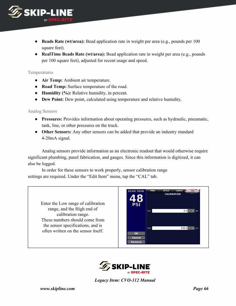
In order for these sensors to work properly, sensor calibration range settings are required. Under the “Edit Item” menu, tap the “CAL” tab.
Enter the Low range of calibration range, and the High end of
calibration range. These numbers should come from the sensor specifications, and is often written on the sensor itself.
Legacy Item: CVO-312 Manual
www.skipline.com Page 66
Digital Sensors
● RPM: Detects RPM of auxiliary equipment on the vehicle. ● Other Sensors: Frequency, pulse counting, counters, and other methods of processing
pulses and level signals can be sensed and reported to the operator.
Thermocouple Sensors
● Yellow/White/Black Tank Temp: Temperatures of material at the tank. ● Yellow/White/Black Line Temp: Temperatures at some point in the line. This sensor is
often placed at the material heat exchanger. ● Glycol Temp: For systems that use glycol as a material heat source, this temperature can
also be monitored.
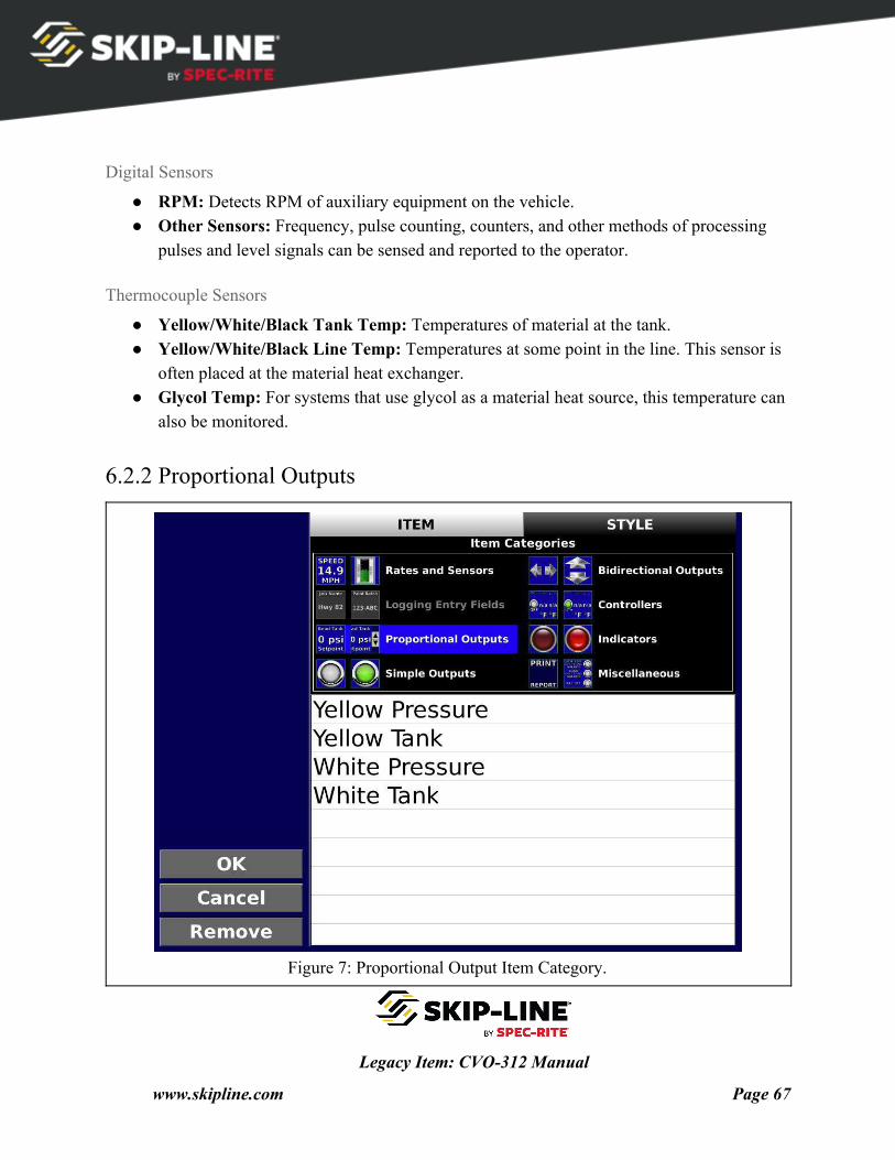
6.2.2 Proportional Outputs
Figure 7: Proportional Output Item Category.
Legacy Item: CVO-312 Manual
www.skipline.com Page 67
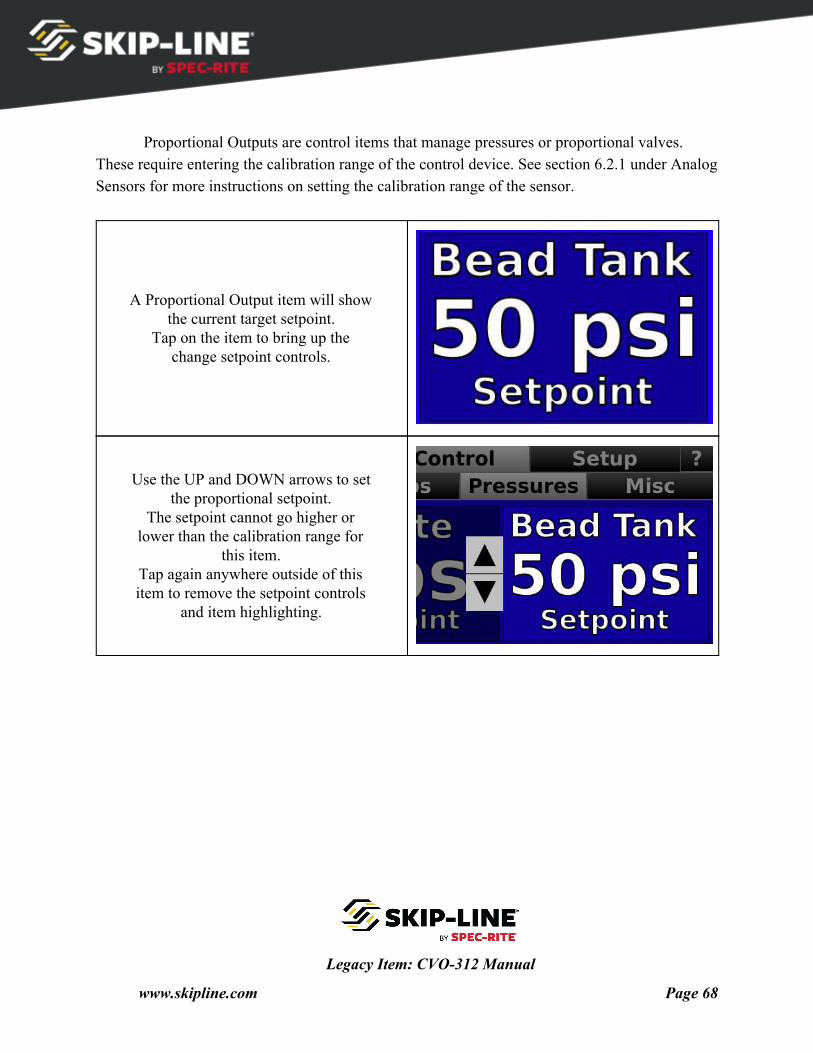
Proportional Outputs are control items that manage pressures or proportional valves.
These require entering the calibration range of the control device. See section 6.2.1 under Analog Sensors for more instructions on setting the calibration range of the sensor.
A Proportional Output item will show the current target setpoint.
Tap on the item to bring up the change setpoint controls.
Use the UP and DOWN arrows to set the proportional setpoint.
The setpoint cannot go higher or lower than the calibration range for
this item. Tap again anywhere outside of this item to remove the setpoint controls
and item highlighting.
Legacy Item: CVO-312 Manual
www.skipline.com Page 68
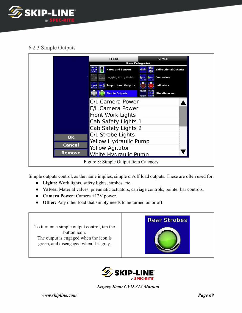
6.2.3 Simple Outputs
Figure 8: Simple Output Item Category
Simple outputs control, as the name implies, simple on/off load outputs. These are often used for:
● Lights: Work lights, safety lights, strobes, etc. ● Valves: Material valves, pneumatic actuators, carriage controls, pointer bar controls. ● Camera Power: Camera +12V power. ● Other: Any other load that simply needs to be turned on or off.
To turn on a simple output control, tap the button icon.
The output is engaged when the icon is green, and disengaged when it is gray.
Legacy Item: CVO-312 Manual
www.skipline.com Page 69
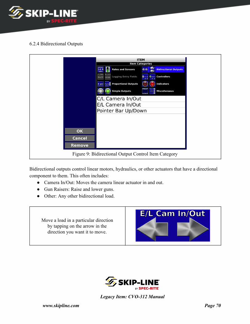
6.2.4 Bidirectional Outputs
Figure 9: Bidirectional Output Control Item Category
Bidirectional outputs control linear motors, hydraulics, or other actuators that have a directional component to them. This often includes:
● Camera In/Out: Moves the camera linear actuator in and out. ● Gun Raisers: Raise and lower guns. ● Other: Any other bidirectional load.
Move a load in a particular direction by tapping on the arrow in the direction you want it to move.
Legacy Item: CVO-312 Manual
www.skipline.com Page 70
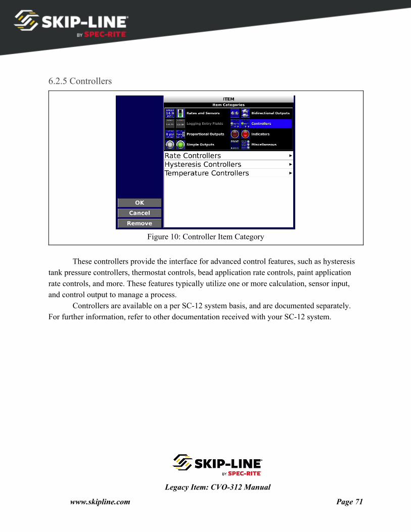
6.2.5 Controllers
Figure 10: Controller Item Category
These controllers provide the interface for advanced control features, such as hysteresis
tank pressure controllers, thermostat controls, bead application rate controls, paint application rate controls, and more. These features typically utilize one or more calculation, sensor input, and control output to manage a process.
Controllers are available on a per SC-12 system basis, and are documented separately. For further information, refer to other documentation received with your SC-12 system.
Legacy Item: CVO-312 Manual
www.skipline.com Page 71
6.2.6 Indicators
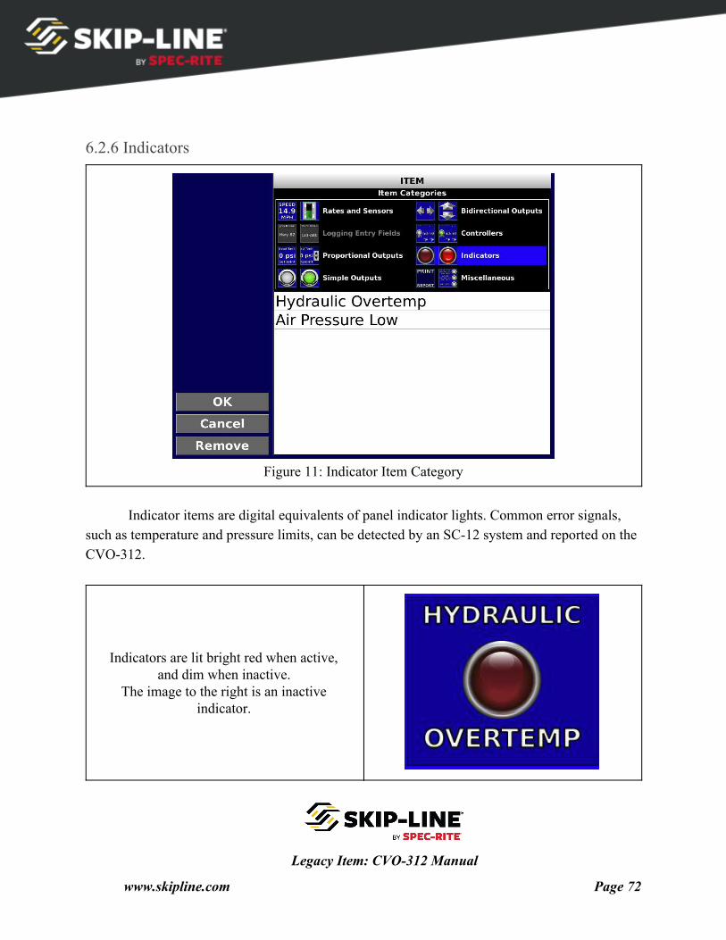
Figure 11: Indicator Item Category
Indicator items are digital equivalents of panel indicator lights. Common error signals,
such as temperature and pressure limits, can be detected by an SC-12 system and reported on the CVO-312.
Indicators are lit bright red when active, and dim when inactive.
The image to the right is an inactive indicator.
Legacy Item: CVO-312 Manual
www.skipline.com Page 72
6.2.7 Miscellaneous
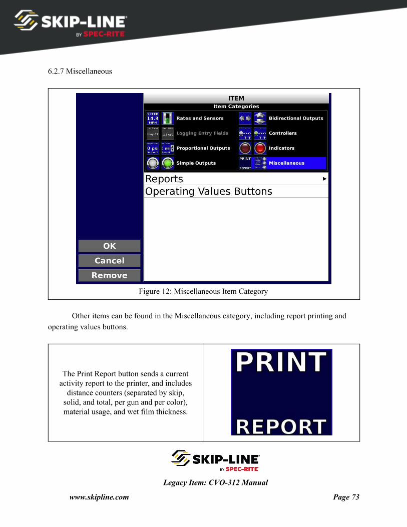
Figure 12: Miscellaneous Item Category
Other items can be found in the Miscellaneous category, including report printing and
operating values buttons.
The Print Report button sends a current activity report to the printer, and includes
distance counters (separated by skip, solid, and total, per gun and per color), material usage, and wet film thickness.
Legacy Item: CVO-312 Manual
www.skipline.com Page 73
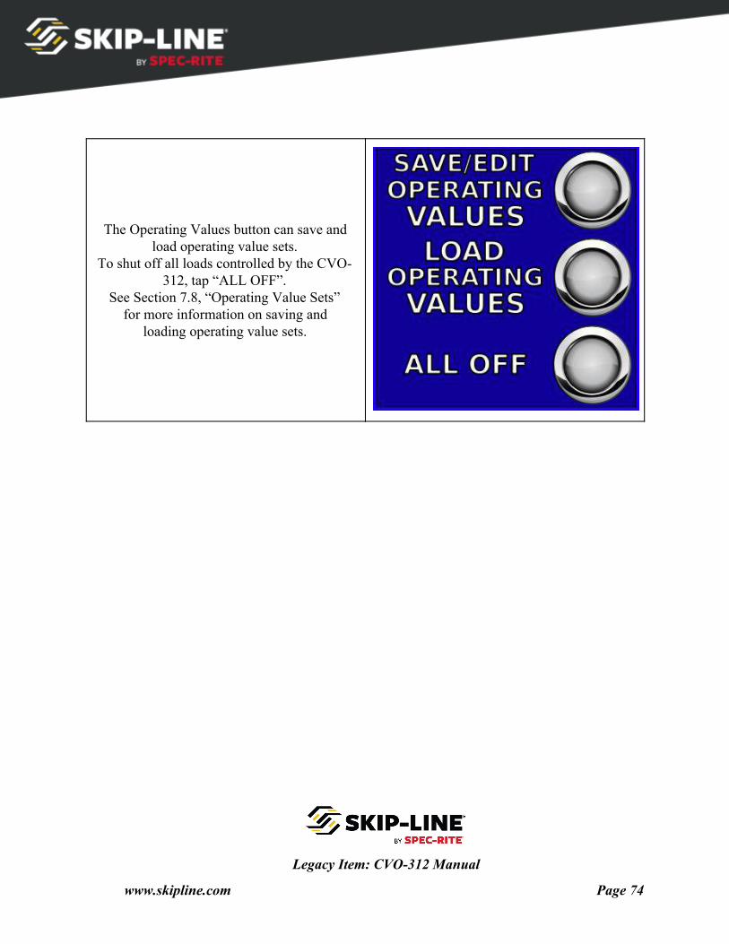
The Operating Values button can save and load operating value sets.
To shut off all loads controlled by the CVO- 312, tap “ALL OFF”.
See Section 7.8, “Operating Value Sets” for more information on saving and
loading operating value sets.
Legacy Item: CVO-312 Manual
www.skipline.com Page 74
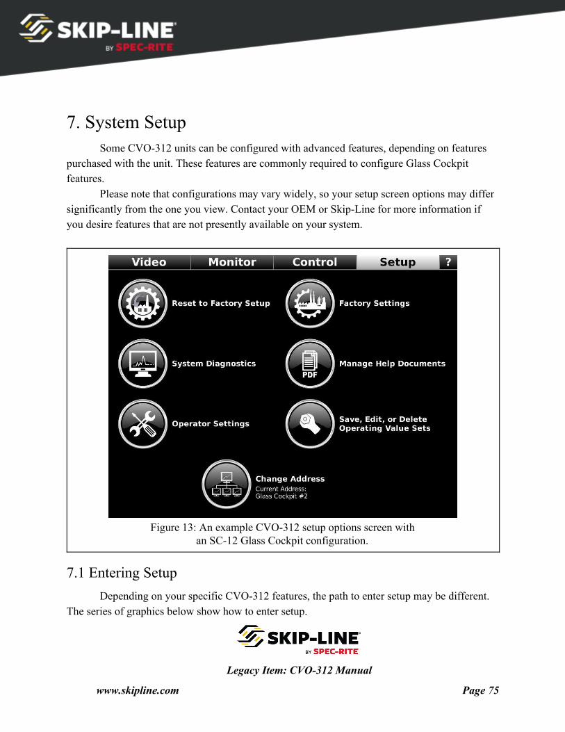
7. System Setup Some CVO-312 units can be configured with advanced features, depending on features
purchased with the unit. These features are commonly required to configure Glass Cockpit features.
Please note that configurations may vary widely, so your setup screen options may differ significantly from the one you view. Contact your OEM or Skip-Line for more information if you desire features that are not presently available on your system.
Figure 13: An example CVO-312 setup options screen with
an SC-12 Glass Cockpit configuration.
7.1 Entering Setup Depending on your specific CVO-312 features, the path to enter setup may be different.
The series of graphics below show how to enter setup.
Legacy Item: CVO-312 Manual
www.skipline.com Page 75
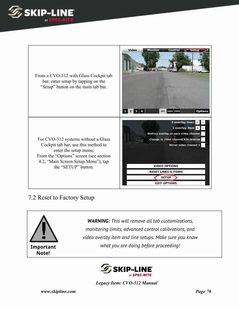
From a CVO-312 with Glass Cockpit tab bar, enter setup by tapping on the
“Setup” button on the main tab bar.
For CVO-312 systems without a Glass Cockpit tab bar, use this method to
enter the setup menu. From the “Options” screen (see section 4.2, “Main Screen Setup Menu”), tap
the “SETUP” button.
7.2 Reset to Factory Setup
Important Note!
WARNING: This will remove all tab customizations,
monitoring limits, advanced control calibrations, and
video overlay item and line setups. Make sure you know
what you are doing before proceeding!
Legacy Item: CVO-312 Manual
www.skipline.com Page 76
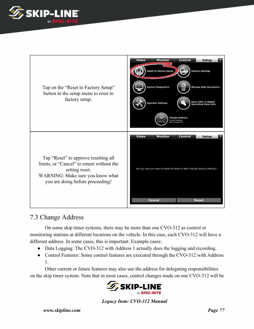
Tap on the “Reset to Factory Setup” button in the setup menu to reset to
factory setup.
Tap “Reset” to approve resetting all limits, or “Cancel” to return without the
setting reset. WARNING: Make sure you know what
you are doing before proceeding!
7.3 Change Address On some skip timer systems, there may be more than one CVO-312 as control or
monitoring stations at different locations on the vehicle. In this case, each CVO-312 will have a different address. In some cases, this is important. Example cases:
● Data Logging: The CVO-312 with Address 1 actually does the logging and recording. ● Control Features: Some control features are executed through the CVO-312 with Address
1. Other current or future features may also use the address for delegating responsibilities
on the skip timer system. Note that in most cases, control changes made on one CVO-312 will be
Legacy Item: CVO-312 Manual
www.skipline.com Page 77
immediately reflected on all CVO-312s on the same vehicle. However, only one can actually be in control certain processes.
If you receive a warning about multiple CVO-312s with the same address, follow the instructions here to correctly identify the CVO-312s on your system.
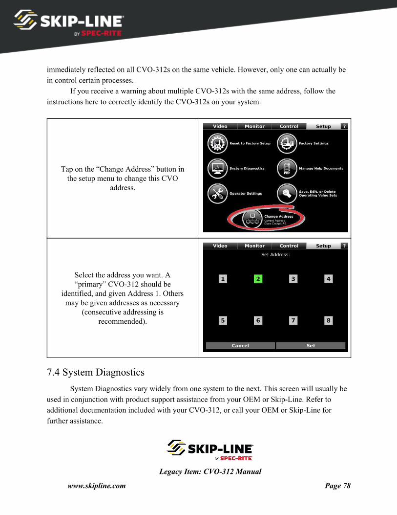
Tap on the “Change Address” button in the setup menu to change this CVO
address.
Select the address you want. A “primary” CVO-312 should be
identified, and given Address 1. Others may be given addresses as necessary
(consecutive addressing is recommended).
7.4 System Diagnostics System Diagnostics vary widely from one system to the next. This screen will usually be
used in conjunction with product support assistance from your OEM or Skip-Line. Refer to additional documentation included with your CVO-312, or call your OEM or Skip-Line for further assistance.
Legacy Item: CVO-312 Manual
www.skipline.com Page 78
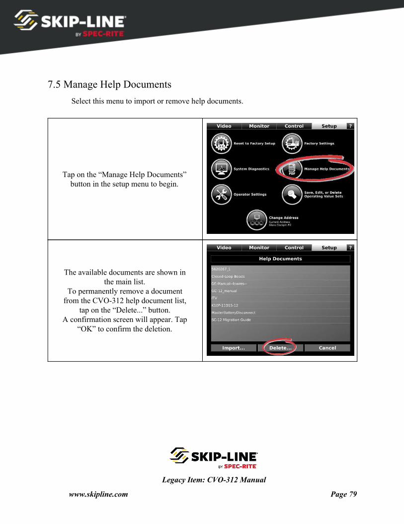
7.5 Manage Help Documents Select this menu to import or remove help documents.
Tap on the “Manage Help Documents” button in the setup menu to begin.
The available documents are shown in the main list.
To permanently remove a document from the CVO-312 help document list,
tap on the “Delete...” button. A confirmation screen will appear. Tap
“OK” to confirm the deletion.
Legacy Item: CVO-312 Manual
www.skipline.com Page 79
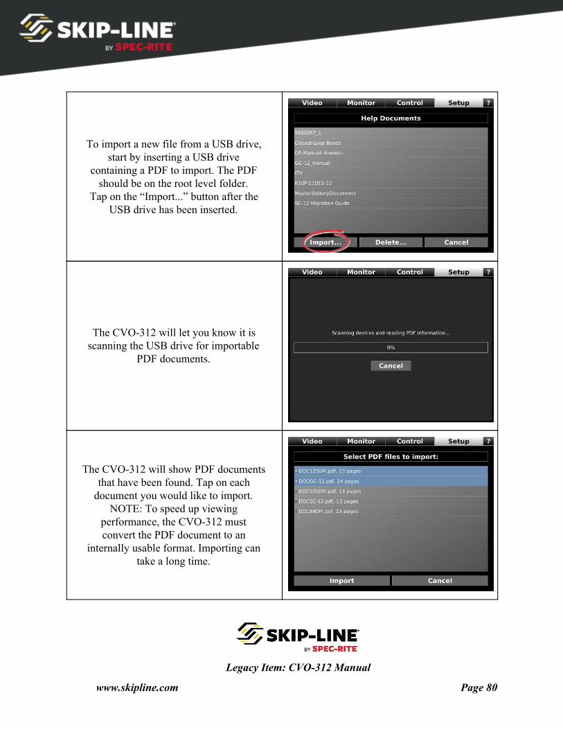
To import a new file from a USB drive, start by inserting a USB drive
containing a PDF to import. The PDF should be on the root level folder.
Tap on the “Import...” button after the USB drive has been inserted.
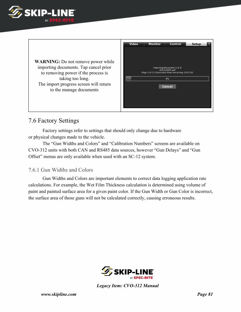
The CVO-312 will let you know it is scanning the USB drive for importable
PDF documents.
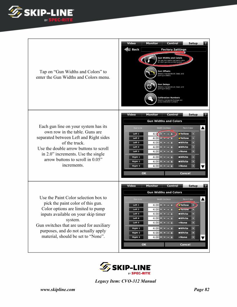
The CVO-312 will show PDF documents that have been found. Tap on each
document you would like to import. NOTE: To speed up viewing
performance, the CVO-312 must convert the PDF document to an
internally usable format. Importing can take a long time.
Legacy Item: CVO-312 Manual
www.skipline.com Page 80
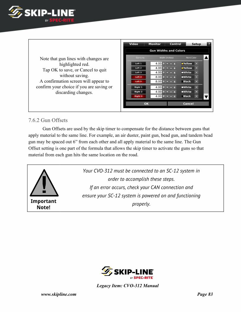
WARNING: Do not remove power while importing documents. Tap cancel prior
to removing power if the process is taking too long.
The import progress screen will return to the manage documents
7.6 Factory Settings Factory settings refer to settings that should only change due to hardware
or physical changes made to the vehicle. The “Gun Widths and Colors” and “Calibration Numbers” screens are available on
CVO-312 units with both CAN and RS485 data sources, however “Gun Delays” and “Gun Offset” menus are only available when used with an SC-12 system.
7.6.1 Gun Widths and Colors Gun Widths and Colors are important elements to correct data logging application rate
calculations. For example, the Wet Film Thickness calculation is determined using volume of paint and painted surface area for a given paint color. If the Gun Width or Gun Color is incorrect, the surface area of those guns will not be calculated correctly, causing erroneous results.
Legacy Item: CVO-312 Manual
www.skipline.com Page 81
Tap on “Gun Widths and Colors” to enter the Gun Widths and Colors menu.
Each gun line on your system has its own row in the table. Guns are
separated between Left and Right sides of the truck.
Use the double arrow buttons to scroll in 2.0” increments. Use the single
arrow buttons to scroll in 0.05” increments.
Use the Paint Color selection box to pick the paint color of this gun.
Color options are limited to pump inputs available on your skip timer
system. Gun switches that are used for auxiliary
purposes, and do not actually apply material, should be set to “None”.
Legacy Item: CVO-312 Manual
www.skipline.com Page 82
Note that gun lines with changes are highlighted red.
Tap OK to save, or Cancel to quit without saving.
A confirmation screen will appear to confirm your choice if you are saving or
discarding changes.
7.6.2 Gun Offsets Gun Offsets are used by the skip timer to compensate for the distance between guns that
apply material to the same line. For example, an air duster, paint gun, bead gun, and tandem bead gun may be spaced out 6” from each other and all apply material to the same line. The Gun Offset setting is one part of the formula that allows the skip timer to activate the guns so that material from each gun hits the same location on the road.
Important Note!
Your CVO-312 must be connected to an SC-12 system in
order to accomplish these steps.
If an error occurs, check your CAN connection and
ensure your SC-12 system is powered on and functioning
properly.
Legacy Item: CVO-312 Manual
www.skipline.com Page 83
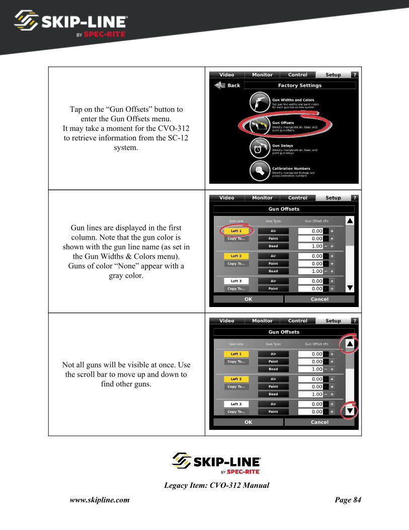
Tap on the “Gun Offsets” button to enter the Gun Offsets menu.
It may take a moment for the CVO-312 to retrieve information from the SC-12
system.
Gun lines are displayed in the first column. Note that the gun color is
shown with the gun line name (as set in the Gun Widths & Colors menu).
Guns of color “None” appear with a gray color.
Not all guns will be visible at once. Use the scroll bar to move up and down to
find other guns.
Legacy Item: CVO-312 Manual
www.skipline.com Page 84
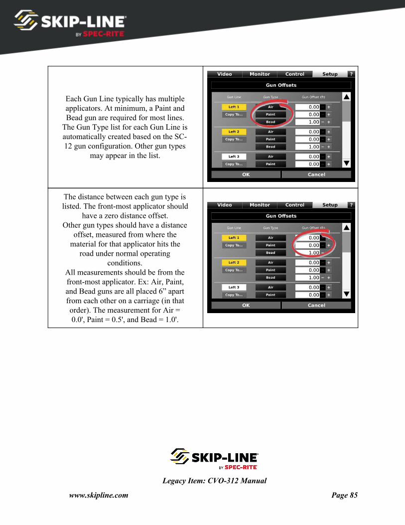
Each Gun Line typically has multiple applicators. At minimum, a Paint and Bead gun are required for most lines.
The Gun Type list for each Gun Line is automatically created based on the SC- 12 gun configuration. Other gun types
may appear in the list.
The distance between each gun type is listed. The front-most applicator should
have a zero distance offset. Other gun types should have a distance
offset, measured from where the material for that applicator hits the
road under normal operating conditions.
All measurements should be from the front-most applicator. Ex: Air, Paint, and Bead guns are all placed 6” apart from each other on a carriage (in that order). The measurement for Air = 0.0', Paint = 0.5', and Bead = 1.0'.
Legacy Item: CVO-312 Manual
www.skipline.com Page 85
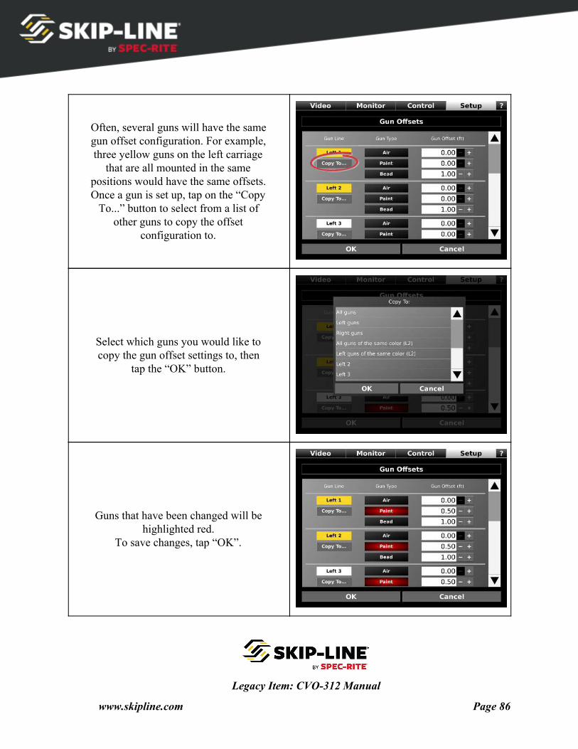
Often, several guns will have the same gun offset configuration. For example, three yellow guns on the left carriage
that are all mounted in the same positions would have the same offsets. Once a gun is set up, tap on the “Copy
To...” button to select from a list of other guns to copy the offset
configuration to.
Select which guns you would like to copy the gun offset settings to, then
tap the “OK” button.
Guns that have been changed will be highlighted red.
To save changes, tap “OK”.
Legacy Item: CVO-312 Manual
www.skipline.com Page 86
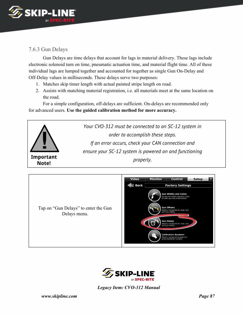
7.6.3 Gun Delays Gun Delays are time delays that account for lags in material delivery. These lags include
electronic solenoid turn on time, pneumatic actuation time, and material flight time. All of these individual lags are lumped together and accounted for together as single Gun On-Delay and Off-Delay values in milliseconds. These delays serve two purposes:
1. Matches skip timer length with actual painted stripe length on road. 2. Assists with matching material registration, i.e. all materials meet at the same location on
the road. For a simple configuration, off-delays are sufficient. On-delays are recommended only
for advanced users. Use the guided calibration method for more accuracy.
Important Note!
Your CVO-312 must be connected to an SC-12 system in
order to accomplish these steps.
If an error occurs, check your CAN connection and
ensure your SC-12 system is powered on and functioning
properly.
Tap on “Gun Delays” to enter the Gun Delays menu.
Legacy Item: CVO-312 Manual
www.skipline.com Page 87

Gun lines are displayed in the first column. Note that the gun color is
shown with the gun line name (as set in the Gun Widths & Colors menu).
Guns of color “None” appear with a gray color.
Not all guns will be visible at once. Use the scroll bar to move up and down to
find other guns.
Each Gun Line typically has multiple applicators. Each applicator will have
different delays associated. The Gun Type list for each Gun Line is automatically created based on the SC-
12 gun configuration.
Legacy Item: CVO-312 Manual
www.skipline.com Page 88
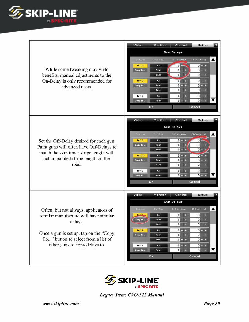
While some tweaking may yield benefits, manual adjustments to the On-Delay is only recommended for
advanced users.
Set the Off-Delay desired for each gun. Paint guns will often have Off-Delays to match the skip timer stripe length with
actual painted stripe length on the road.
Often, but not always, applicators of similar manufacture will have similar
delays.
Once a gun is set up, tap on the “Copy To...” button to select from a list of
other guns to copy delays to.
Legacy Item: CVO-312 Manual
www.skipline.com Page 89
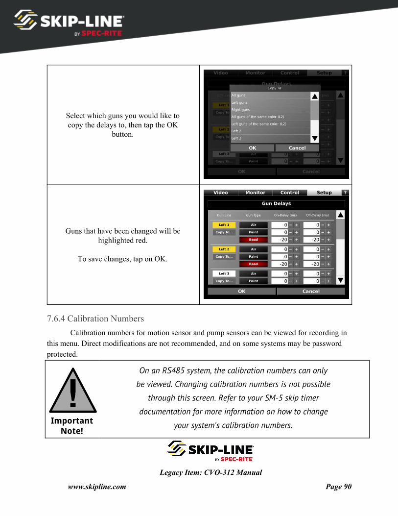
Select which guns you would like to copy the delays to, then tap the OK
button.
Guns that have been changed will be highlighted red.
To save changes, tap on OK.
7.6.4 Calibration Numbers Calibration numbers for motion sensor and pump sensors can be viewed for recording in
this menu. Direct modifications are not recommended, and on some systems may be password protected.
Important Note!
On an RS485 system, the calibration numbers can only
be viewed. Changing calibration numbers is not possible
through this screen. Refer to your SM-5 skip timer
documentation for more information on how to change
your system's calibration numbers.
Legacy Item: CVO-312 Manual
www.skipline.com Page 90
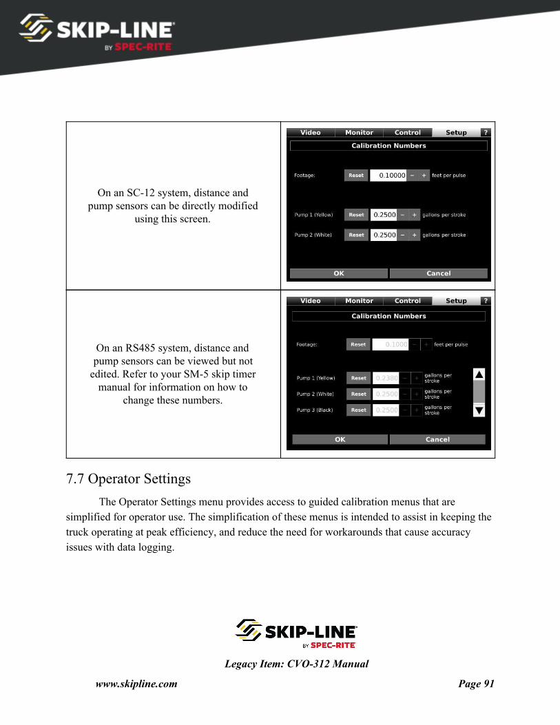
On an SC-12 system, distance and pump sensors can be directly modified
using this screen.
On an RS485 system, distance and pump sensors can be viewed but not
edited. Refer to your SM-5 skip timer manual for information on how to
change these numbers.
7.7 Operator Settings The Operator Settings menu provides access to guided calibration menus that are
simplified for operator use. The simplification of these menus is intended to assist in keeping the truck operating at peak efficiency, and reduce the need for workarounds that cause accuracy issues with data logging.
Legacy Item: CVO-312 Manual
www.skipline.com Page 91
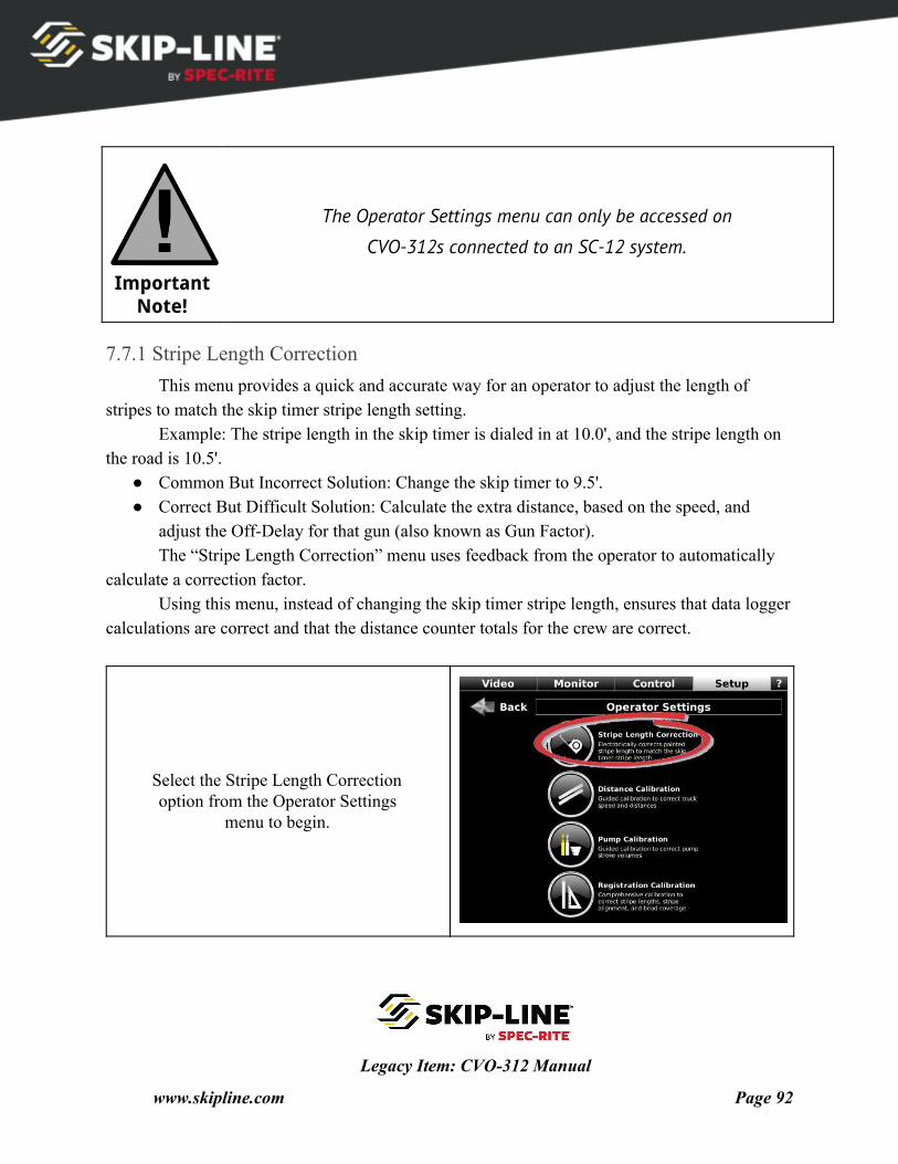
Important Note!
The Operator Settings menu can only be accessed on
CVO-312s connected to an SC-12 system.
7.7.1 Stripe Length Correction This menu provides a quick and accurate way for an operator to adjust the length of
stripes to match the skip timer stripe length setting. Example: The stripe length in the skip timer is dialed in at 10.0', and the stripe length on
the road is 10.5'. ● Common But Incorrect Solution: Change the skip timer to 9.5'. ● Correct But Difficult Solution: Calculate the extra distance, based on the speed, and
adjust the Off-Delay for that gun (also known as Gun Factor). The “Stripe Length Correction” menu uses feedback from the operator to automatically
calculate a correction factor. Using this menu, instead of changing the skip timer stripe length, ensures that data logger
calculations are correct and that the distance counter totals for the crew are correct.
Select the Stripe Length Correction option from the Operator Settings
menu to begin.
Legacy Item: CVO-312 Manual
www.skipline.com Page 92
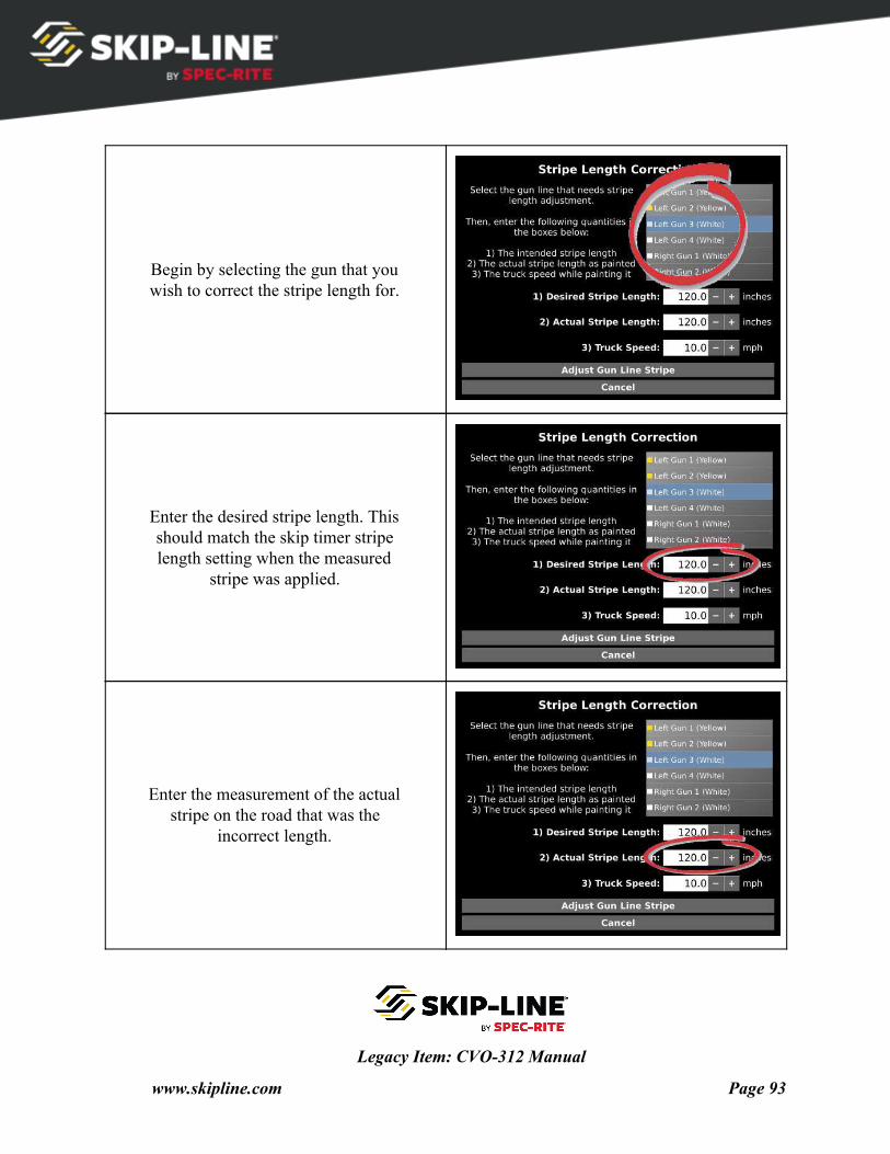
Begin by selecting the gun that you wish to correct the stripe length for.
Enter the desired stripe length. This should match the skip timer stripe length setting when the measured
stripe was applied.
Enter the measurement of the actual stripe on the road that was the
incorrect length.
Legacy Item: CVO-312 Manual
www.skipline.com Page 93
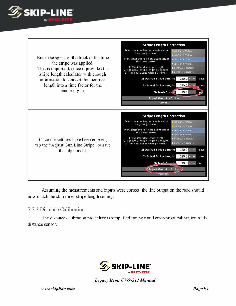
Enter the speed of the truck at the time the stripe was applied.
This is important, since it provides the stripe length calculator with enough information to convert the incorrect
length into a time factor for the material gun.
Once the settings have been entered, tap the “Adjust Gun Line Stripe” to save
the adjustment.
Assuming the measurements and inputs were correct, the line output on the road should
now match the skip timer stripe length setting.
7.7.2 Distance Calibration The distance calibration procedure is simplified for easy and error-proof calibration of the
distance sensor.
Legacy Item: CVO-312 Manual
www.skipline.com Page 94
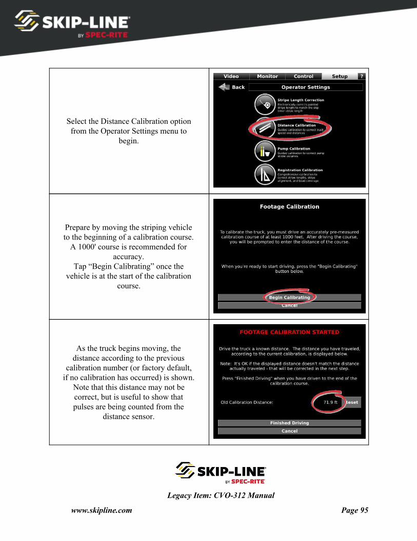
Select the Distance Calibration option from the Operator Settings menu to
begin.
Prepare by moving the striping vehicle to the beginning of a calibration course.
A 1000' course is recommended for accuracy.
Tap “Begin Calibrating” once the vehicle is at the start of the calibration
course.
As the truck begins moving, the distance according to the previous
calibration number (or factory default, if no calibration has occurred) is shown.
Note that this distance may not be correct, but is useful to show that pulses are being counted from the
distance sensor.
Legacy Item: CVO-312 Manual
www.skipline.com Page 95
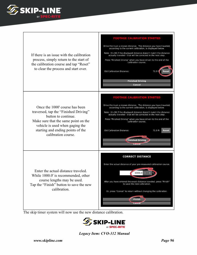
If there is an issue with the calibration process, simply return to the start of
the calibration course and tap “Reset” to clear the process and start over.
Once the 1000' course has been traversed, tap the “Finished Driving”
button to continue. Make sure that the same point on the
vehicle is used when gaging the starting and ending points of the
calibration course.
Enter the actual distance traveled. While 1000.0' is recommended, other
course lengths may be used. Tap the “Finish” button to save the new
calibration.
The skip timer system will now use the new distance calibration.
Legacy Item: CVO-312 Manual
www.skipline.com Page 96
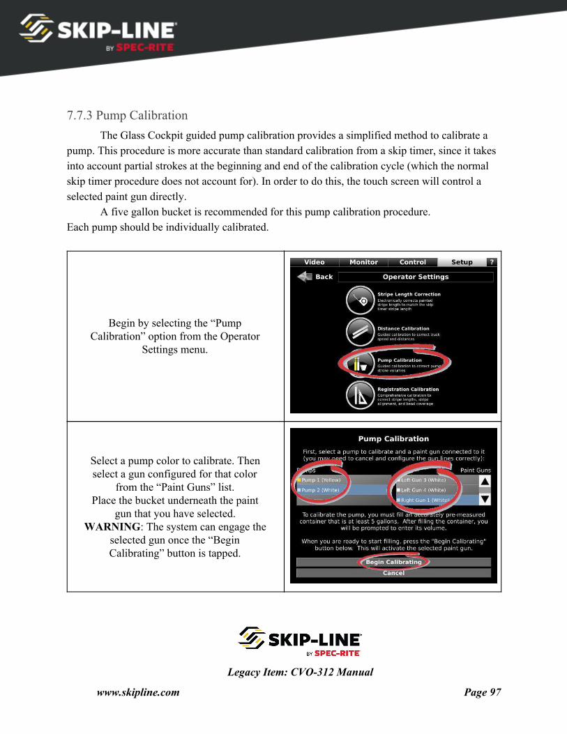
7.7.3 Pump Calibration The Glass Cockpit guided pump calibration provides a simplified method to calibrate a
pump. This procedure is more accurate than standard calibration from a skip timer, since it takes into account partial strokes at the beginning and end of the calibration cycle (which the normal skip timer procedure does not account for). In order to do this, the touch screen will control a selected paint gun directly.
A five gallon bucket is recommended for this pump calibration procedure. Each pump should be individually calibrated.
Begin by selecting the “Pump Calibration” option from the Operator
Settings menu.
Select a pump color to calibrate. Then select a gun configured for that color
from the “Paint Guns” list. Place the bucket underneath the paint
gun that you have selected. WARNING: The system can engage the
selected gun once the “Begin Calibrating” button is tapped.
Legacy Item: CVO-312 Manual
www.skipline.com Page 97
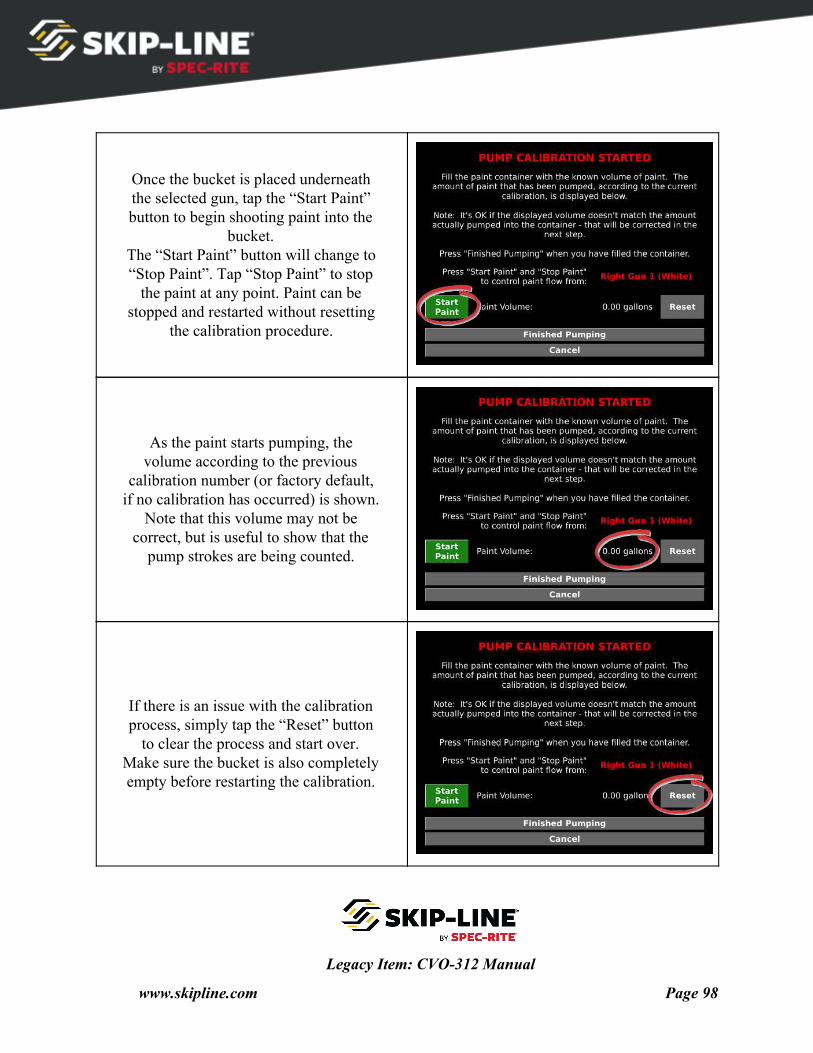
Once the bucket is placed underneath the selected gun, tap the “Start Paint” button to begin shooting paint into the
bucket. The “Start Paint” button will change to “Stop Paint”. Tap “Stop Paint” to stop
the paint at any point. Paint can be stopped and restarted without resetting
the calibration procedure.
As the paint starts pumping, the volume according to the previous
calibration number (or factory default, if no calibration has occurred) is shown.
Note that this volume may not be correct, but is useful to show that the
pump strokes are being counted.
If there is an issue with the calibration process, simply tap the “Reset” button
to clear the process and start over. Make sure the bucket is also completely empty before restarting the calibration.
Legacy Item: CVO-312 Manual
www.skipline.com Page 98
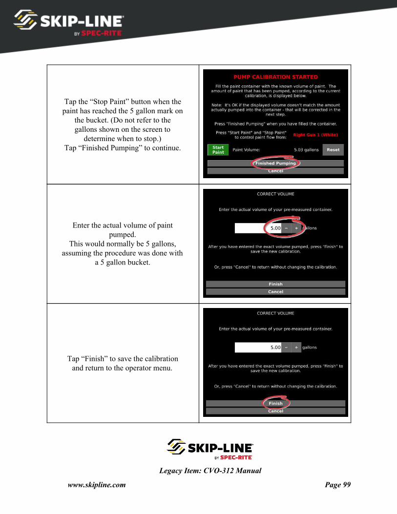
Tap the “Stop Paint” button when the paint has reached the 5 gallon mark on
the bucket. (Do not refer to the gallons shown on the screen to
determine when to stop.) Tap “Finished Pumping” to continue.
Enter the actual volume of paint pumped.
This would normally be 5 gallons, assuming the procedure was done with
a 5 gallon bucket.
Tap “Finish” to save the calibration and return to the operator menu.
Legacy Item: CVO-312 Manual
www.skipline.com Page 99
7.7.4 Registration Calibration With regards to road marking, “registration” refers to matching up material from different
applicators to the same point on the road. For example, good registration means that beads and paint should start and end together on the road. There are many obstacles to proper registration, not all of which will be covered here.
To simplify attaining accurate registration, the “Registration Calibration” menu was created. With a simple test run of the truck, followed with measurements, the CVO-312 can calculate delays for all guns, which accomplishes the following:
● Line lengths correct for each gun ● All lines start together ● Beads land precisely at the start of the paint stripe, and stops at precisely the end of paint
stripe ● These precision improvements are beneficial for more accurate data logging, reduced
material waste, and for better precision with contrast patterns (such as black patterns with black beads). This procedure will calculate On-Delays and Off-Delays for every applicator on the
vehicle. Before starting, make sure gun offsets have been set accurately (see Section 7.6.2, “Gun Offsets”).
Important Note!
The calculations made by this calibration process will be
incorrect if the gun offsets are not accurate.
Make sure gun offsets have already been correctly set
for the current gun configuration.
This procedure will walk you through the following steps:
● Ask for a set of guns to calibrate ● Put down a set of skips from all guns at normal striping speed ● Request measurements for each line
Legacy Item: CVO-312 Manual
www.skipline.com Page 100
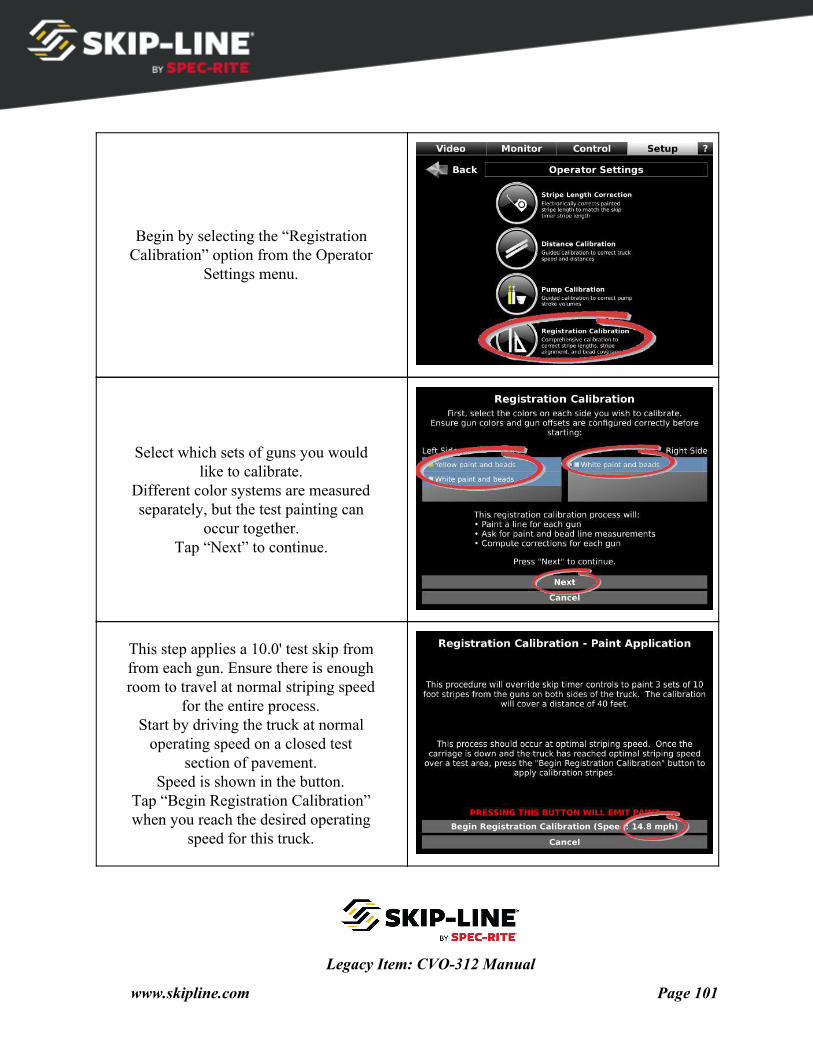
Begin by selecting the “Registration Calibration” option from the Operator
Settings menu.
Select which sets of guns you would like to calibrate.
Different color systems are measured separately, but the test painting can
occur together. Tap “Next” to continue.
This step applies a 10.0' test skip from from each gun. Ensure there is enough room to travel at normal striping speed
for the entire process. Start by driving the truck at normal
operating speed on a closed test section of pavement.
Speed is shown in the button. Tap “Begin Registration Calibration” when you reach the desired operating
speed for this truck.
Legacy Item: CVO-312 Manual
www.skipline.com Page 101
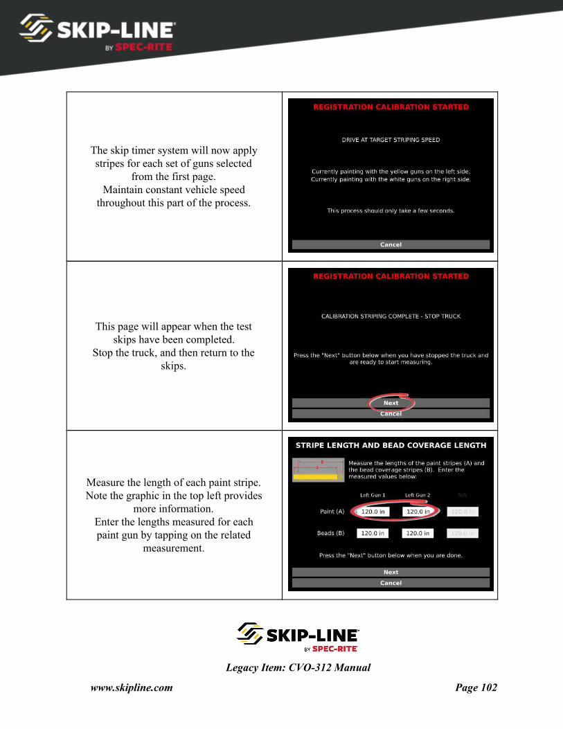
The skip timer system will now apply stripes for each set of guns selected
from the first page. Maintain constant vehicle speed
throughout this part of the process.
This page will appear when the test skips have been completed.
Stop the truck, and then return to the skips.
Measure the length of each paint stripe. Note the graphic in the top left provides
more information. Enter the lengths measured for each paint gun by tapping on the related
measurement.
Legacy Item: CVO-312 Manual
www.skipline.com Page 102
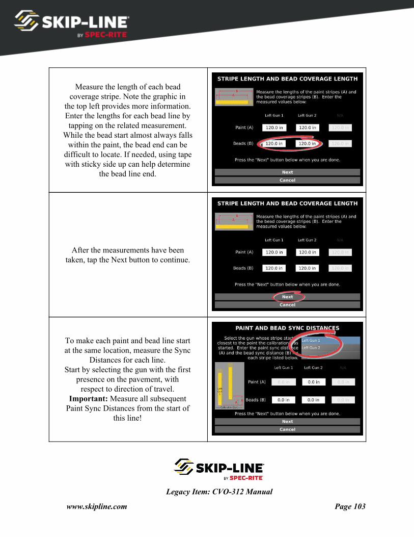
Measure the length of each bead coverage stripe. Note the graphic in
the top left provides more information. Enter the lengths for each bead line by tapping on the related measurement.
While the bead start almost always falls within the paint, the bead end can be
difficult to locate. If needed, using tape with sticky side up can help determine
the bead line end.
After the measurements have been taken, tap the Next button to continue.
To make each paint and bead line start at the same location, measure the Sync
Distances for each line. Start by selecting the gun with the first
presence on the pavement, with respect to direction of travel.
Important: Measure all subsequent Paint Sync Distances from the start of
this line!
Legacy Item: CVO-312 Manual
www.skipline.com Page 103
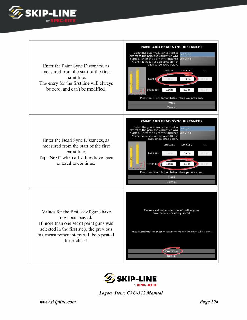
Enter the Paint Sync Distances, as measured from the start of the first
paint line. The entry for the first line will always
be zero, and can't be modified.
Enter the Bead Sync Distances, as measured from the start of the first
paint line. Tap “Next” when all values have been
entered to continue.
Values for the first set of guns have now been saved.
If more than one set of paint guns was selected in the first step, the previous
six measurement steps will be repeated for each set.
Legacy Item: CVO-312 Manual
www.skipline.com Page 104
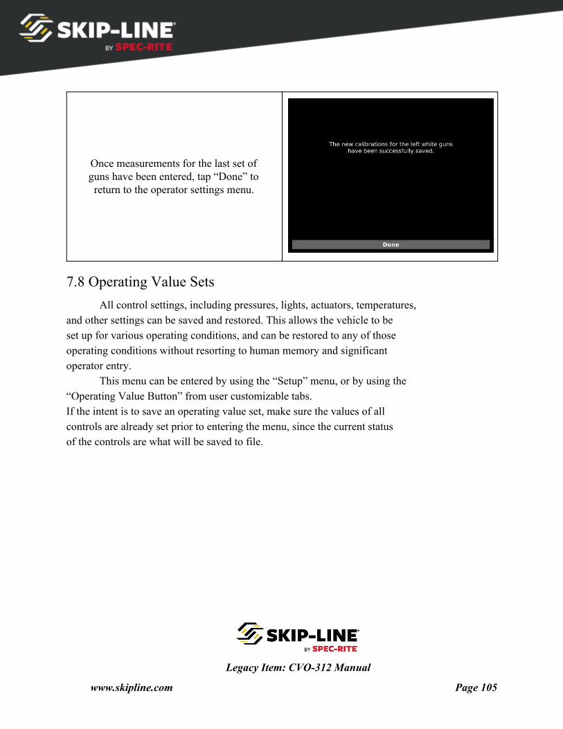
Once measurements for the last set of guns have been entered, tap “Done” to return to the operator settings menu.
7.8 Operating Value Sets All control settings, including pressures, lights, actuators, temperatures,
and other settings can be saved and restored. This allows the vehicle to be set up for various operating conditions, and can be restored to any of those operating conditions without resorting to human memory and significant operator entry.
This menu can be entered by using the “Setup” menu, or by using the “Operating Value Button” from user customizable tabs. If the intent is to save an operating value set, make sure the values of all controls are already set prior to entering the menu, since the current status of the controls are what will be saved to file.
Legacy Item: CVO-312 Manual
www.skipline.com Page 105
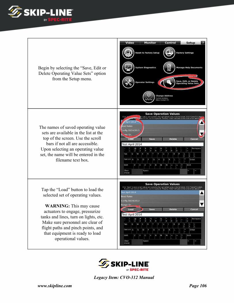
Begin by selecting the “Save, Edit or Delete Operating Value Sets” option
from the Setup menu.
The names of saved operating value sets are available in the list at the top of the screen. Use the scroll
bars if not all are accessible. Upon selecting an operating value set, the name will be entered in the
filename text box.
Tap the “Load” button to load the selected set of operating values.
WARNING: This may cause actuators to engage, pressurize
tanks and lines, turn on lights, etc. Make sure personnel are clear of flight paths and pinch points, and that equipment is ready to load
operational values.
Legacy Item: CVO-312 Manual
www.skipline.com Page 106
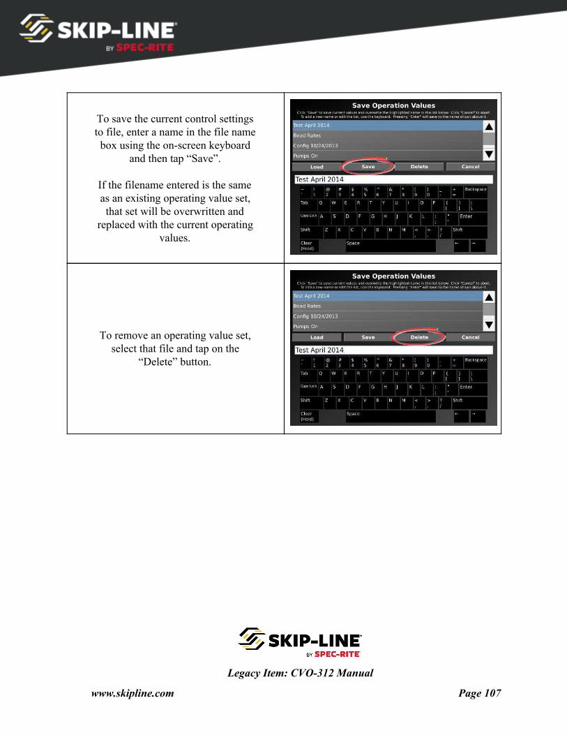
To save the current control settings to file, enter a name in the file name box using the on-screen keyboard
and then tap “Save”.
If the filename entered is the same as an existing operating value set, that set will be overwritten and
replaced with the current operating values.
To remove an operating value set, select that file and tap on the
“Delete” button.
Legacy Item: CVO-312 Manual
www.skipline.com Page 107
8. System Updates The CVO-312 can receive system updates through a USB flash drive. The
update file can provide feature updates, unlock newly purchased features, correct software bugs, and more.
The update file can be delivered via web or email.
Important Note!
Most CVO-312 update files only work on a single vehicle,
and cannot be used on other systems.
Check with your OEM or Skip-Line for more information.
To install a CVO-312 system update:
1. Save the file "update.bin" to a USB flash drive. Make sure the file is named update.bin and it is not inside any folders on the flash drive.
2. Safely eject the USB flash drive from your computer. 3. Plug the flash drive into the Glass Cockpit's unused USB port while the Glass Cockpit is
already powered on. 4. You should see a screen appear within a few seconds that says "Installing update". Once
it has finished, it will ask you to remove the USB drive, remove power for 60 seconds, and power the system back on.
5. Repeat on each Glass Cockpit device on the vehicle.
Legacy Item: CVO-312 Manual
www.skipline.com Page 108
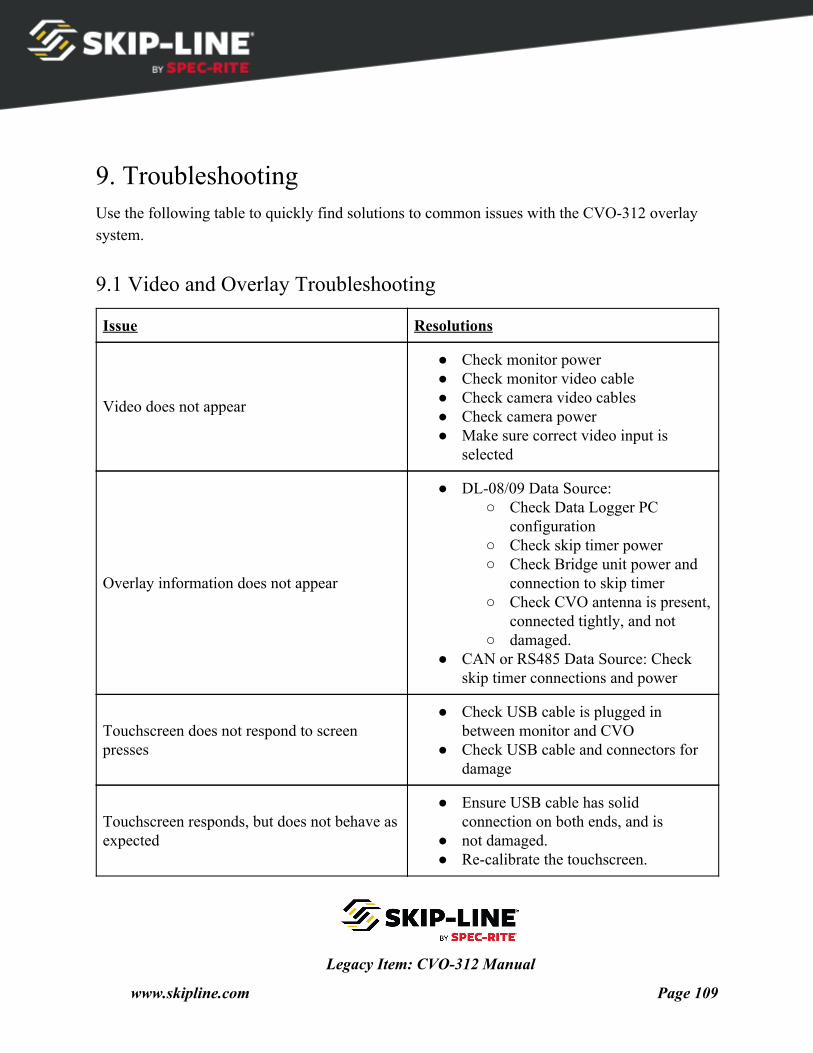
9. Troubleshooting Use the following table to quickly find solutions to common issues with the CVO-312 overlay system.
9.1 Video and Overlay Troubleshooting
Issue Resolutions
Video does not appear
● Check monitor power ● Check monitor video cable ● Check camera video cables ● Check camera power ● Make sure correct video input is
selected
Overlay information does not appear
● DL-08/09 Data Source: ○ Check Data Logger PC
configuration ○ Check skip timer power ○ Check Bridge unit power and
connection to skip timer ○ Check CVO antenna is present,
connected tightly, and not ○ damaged.
● CAN or RS485 Data Source: Check skip timer connections and power
Touchscreen does not respond to screen presses
● Check USB cable is plugged in between monitor and CVO
● Check USB cable and connectors for damage
Touchscreen responds, but does not behave as expected
● Ensure USB cable has solid connection on both ends, and is
● not damaged. ● Re-calibrate the touchscreen.
Legacy Item: CVO-312 Manual
www.skipline.com Page 109
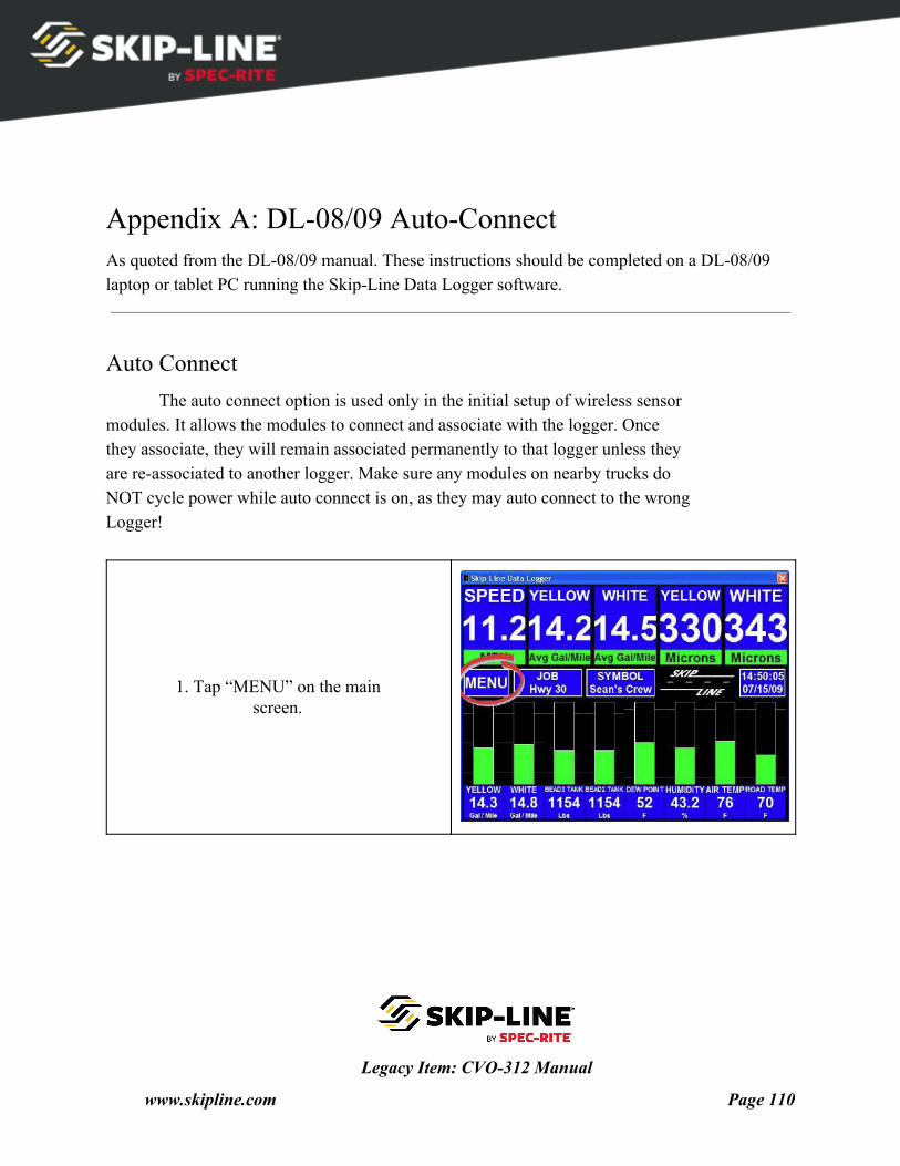
Appendix A: DL-08/09 Auto-Connect As quoted from the DL-08/09 manual. These instructions should be completed on a DL-08/09 laptop or tablet PC running the Skip-Line Data Logger software.
Auto Connect The auto connect option is used only in the initial setup of wireless sensor
modules. It allows the modules to connect and associate with the logger. Once they associate, they will remain associated permanently to that logger unless they are re-associated to another logger. Make sure any modules on nearby trucks do NOT cycle power while auto connect is on, as they may auto connect to the wrong Logger!
1. Tap “MENU” on the main screen.
Legacy Item: CVO-312 Manual
www.skipline.com Page 110
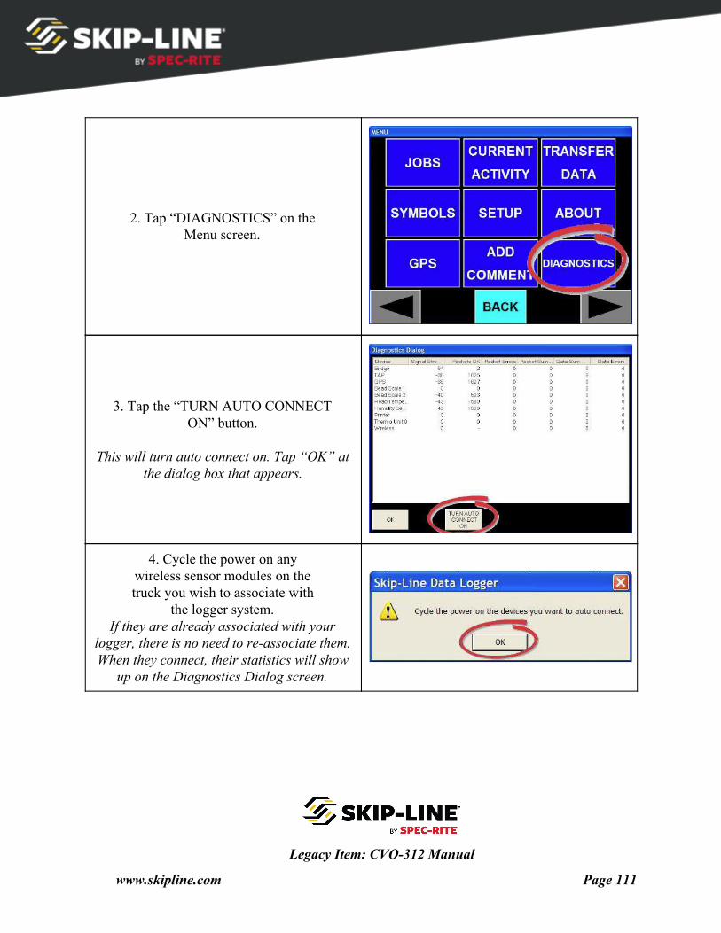
2. Tap “DIAGNOSTICS” on the Menu screen.
3. Tap the “TURN AUTO CONNECT ON” button.
This will turn auto connect on. Tap “OK” at
the dialog box that appears.
4. Cycle the power on any wireless sensor modules on the truck you wish to associate with
the logger system. If they are already associated with your
logger, there is no need to re-associate them. When they connect, their statistics will show
up on the Diagnostics Dialog screen.
Legacy Item: CVO-312 Manual
www.skipline.com Page 111
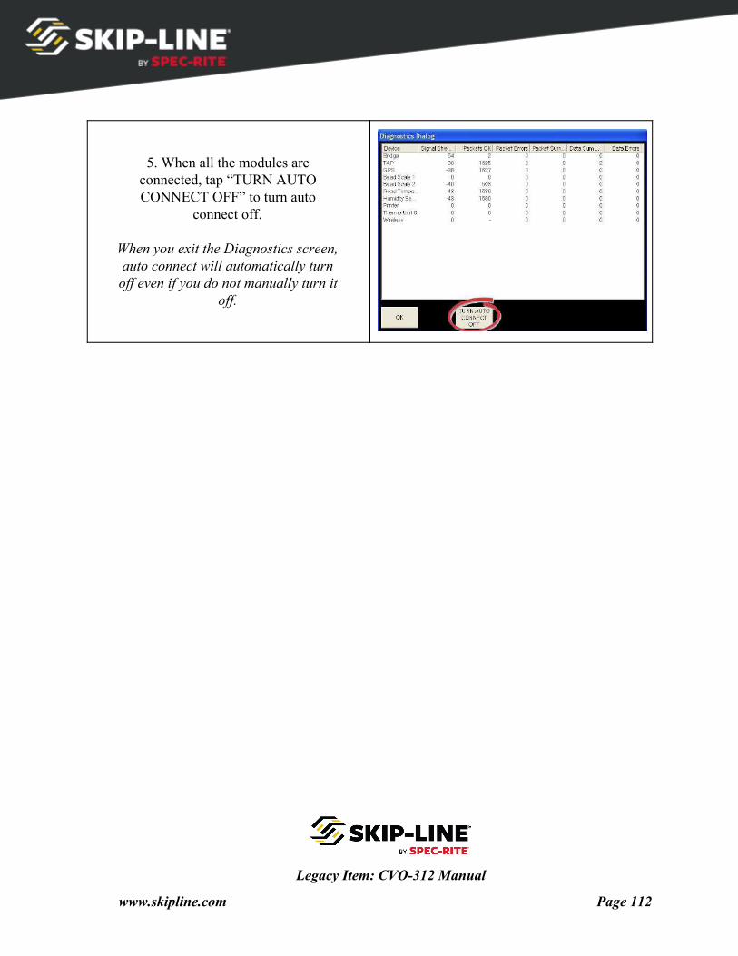
5. When all the modules are connected, tap “TURN AUTO CONNECT OFF” to turn auto
connect off.
When you exit the Diagnostics screen, auto connect will automatically turn off even if you do not manually turn it
off.
Legacy Item: CVO-312 Manual
www.skipline.com Page 112
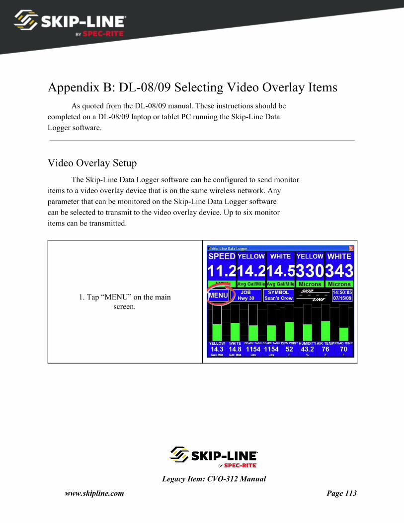
Appendix B: DL-08/09 Selecting Video Overlay Items As quoted from the DL-08/09 manual. These instructions should be
completed on a DL-08/09 laptop or tablet PC running the Skip-Line Data Logger software.
Video Overlay Setup The Skip-Line Data Logger software can be configured to send monitor
items to a video overlay device that is on the same wireless network. Any parameter that can be monitored on the Skip-Line Data Logger software can be selected to transmit to the video overlay device. Up to six monitor items can be transmitted.
1. Tap “MENU” on the main screen.
Legacy Item: CVO-312 Manual
www.skipline.com Page 113
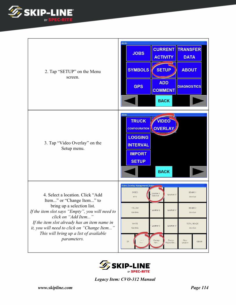
2. Tap “SETUP” on the Menu screen.
3. Tap “Video Overlay” on the Setup menu.
4. Select a location. Click “Add Item...” or “Change Item...” to
bring up a selection list. If the item slot says “Empty”, you will need to
click on “Add Item...” If the item slot already has an item name in
it, you will need to click on “Change Item...” This will bring up a list of available
parameters.
Legacy Item: CVO-312 Manual
www.skipline.com Page 114
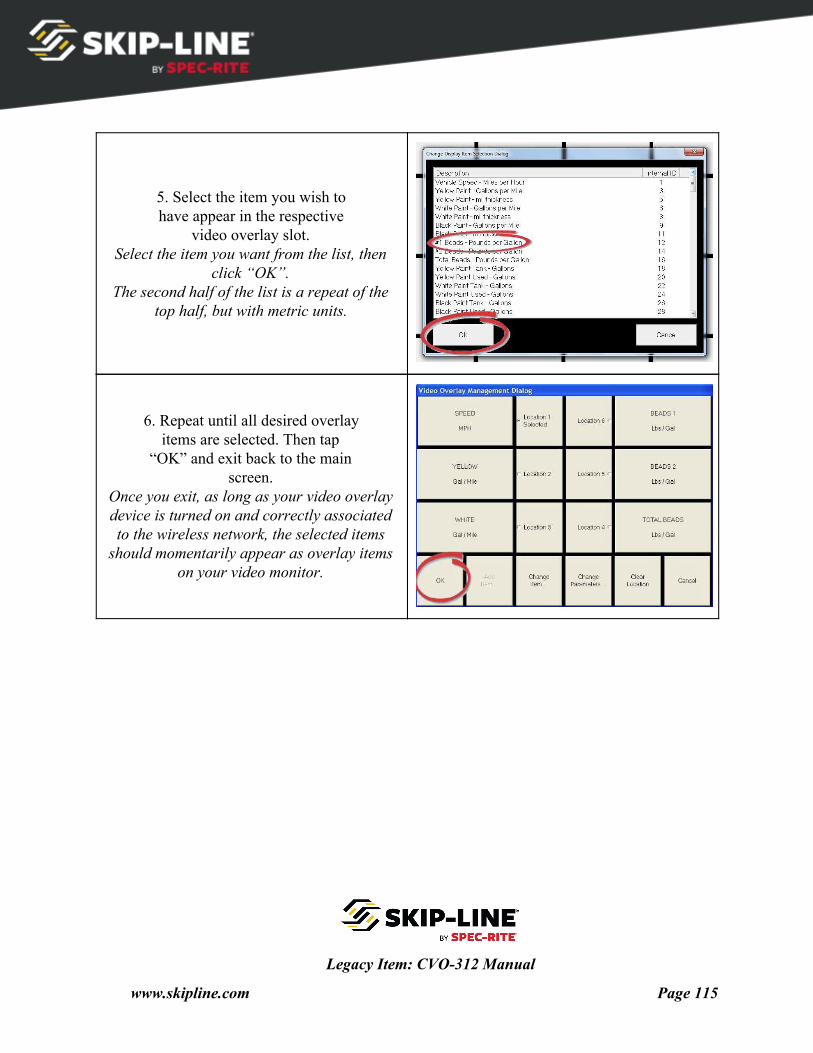
5. Select the item you wish to have appear in the respective
video overlay slot. Select the item you want from the list, then
click “OK”. The second half of the list is a repeat of the
top half, but with metric units.
6. Repeat until all desired overlay items are selected. Then tap
“OK” and exit back to the main screen.
Once you exit, as long as your video overlay device is turned on and correctly associated to the wireless network, the selected items
should momentarily appear as overlay items on your video monitor.
Legacy Item: CVO-312 Manual
www.skipline.com Page 115