Embed Size (px)
Citation preview
X39641318004
SSAAFFEETTYY WWAARRNNIINNGGOnly qualified personnel should install and service the equipment. The installation, starting up, and servicing of heating, ventilating, andair-conditioning equipment can be hazardous and requires specific knowledge and training. Improperly installed, adjusted or alteredequipment by an unqualified person could result in death or serious injury. When working on the equipment, observe all precautions in theliterature and on the tags, stickers, and labels that are attached to the equipment.
October 2019 CCVVHHMM--SSVVXX000011DD--EENN
CVHMWater-Cooled CenTraVac™™ ChillersWith Tracer® AdaptiView™ Control and AdaptiSpeed™Technology
CVHM
Installation, Operation,and Maintenance
©2019 Ingersoll Rand CVHM-SVX001D-EN
IntroductionRead this manual thoroughly before operating orservicing this unit.
Warnings, Cautions, and NoticesSafety advisories appear throughout this manual asrequired. Your personal safety and the properoperation of this machine depend upon the strictobservance of these precautions.
The three types of advisories are defined as follows:
WARNINGIndicates a potentially hazardous situationwhich, if not avoided, could result in death orserious injury.
CAUTIONIndicates a potentially hazardous situationwhich, if not avoided, could result in minor ormoderate injury. It could also be used to alertagainst unsafe practices.
NOTICEIndicates a situation that could result inequipment or property-damage onlyaccidents.
Important Environmental ConcernsScientific research has shown that certain man-madechemicals can affect the earth’s naturally occurringstratospheric ozone layer when released to theatmosphere. In particular, several of the identifiedchemicals that may affect the ozone layer arerefrigerants that contain Chlorine, Fluorine and Carbon(CFCs) and those containing Hydrogen, Chlorine,Fluorine and Carbon (HCFCs). Not all refrigerantscontaining these compounds have the same potentialimpact to the environment. Trane advocates theresponsible handling of all refrigerants-includingindustry replacements for CFCs and HCFCs such assaturated or unsaturated HFCs and HCFCs.
Important Responsible RefrigerantPracticesTrane believes that responsible refrigerant practicesare important to the environment, our customers, andthe air conditioning industry. All technicians whohandle refrigerants must be certified according to localrules. For the USA, the Federal Clean Air Act (Section608) sets forth the requirements for handling,reclaiming, recovering and recycling of certainrefrigerants and the equipment that is used in theseservice procedures. In addition, some states ormunicipalities may have additional requirements thatmust also be adhered to for responsible managementof refrigerants. Know the applicable laws and followthem.
WWAARRNNIINNGGPPrrooppeerr FFiieelldd WWiirriinngg aanndd GGrroouunnddiinnggRReeqquuiirreedd!!FFaaiilluurree ttoo ffoollllooww ccooddee ccoouulldd rreessuulltt iinn ddeeaatthh oorrsseerriioouuss iinnjjuurryy..AAllll ffiieelldd wwiirriinngg MMUUSSTT bbee ppeerrffoorrmmeedd bbyy qquuaalliiffiieeddppeerrssoonnnneell.. IImmpprrooppeerrllyy iinnssttaalllleedd aanndd ggrroouunnddeeddffiieelldd wwiirriinngg ppoosseess FFIIRREE aanndd EELLEECCTTRROOCCUUTTIIOONNhhaazzaarrddss.. TToo aavvooiidd tthheessee hhaazzaarrddss,, yyoouu MMUUSSTT ffoolllloowwrreeqquuiirreemmeennttss ffoorr ffiieelldd wwiirriinngg iinnssttaallllaattiioonn aannddggrroouunnddiinngg aass ddeessccrriibbeedd iinn NNEECC aanndd yyoouurr llooccaall//ssttaattee//nnaattiioonnaall eelleeccttrriiccaall ccooddeess..
WWAARRNNIINNGGPPeerrssoonnaall PPrrootteeccttiivvee EEqquuiippmmeenntt ((PPPPEE))RReeqquuiirreedd!!FFaaiilluurree ttoo wweeaarr pprrooppeerr PPPPEE ffoorr tthhee jjoobb bbeeiinngguunnddeerrttaakkeenn ccoouulldd rreessuulltt iinn ddeeaatthh oorr sseerriioouuss iinnjjuurryy..TTeecchhnniicciiaannss,, iinn oorrddeerr ttoo pprrootteecctt tthheemmsseellvveess ffrroommppootteennttiiaall eelleeccttrriiccaall,, mmeecchhaanniiccaall,, aanndd cchheemmiiccaallhhaazzaarrddss,, MMUUSSTT ffoollllooww pprreeccaauuttiioonnss iinn tthhiiss mmaannuuaallaanndd oonn tthhee ttaaggss,, ssttiicckkeerrss,, aanndd llaabbeellss,, aass wweellll aass tthheeiinnssttrruuccttiioonnss bbeellooww::
•• BBeeffoorree iinnssttaalllliinngg//sseerrvviicciinngg tthhiiss uunniitt,,tteecchhnniicciiaannss MMUUSSTT ppuutt oonn aallll PPPPEE rreeqquuiirreedd ffoorrtthhee wwoorrkk bbeeiinngg uunnddeerrttaakkeenn ((EExxaammpplleess;; ccuuttrreessiissttaanntt gglloovveess//sslleeeevveess,, bbuuttyyll gglloovveess,, ssaaffeettyyggllaasssseess,, hhaarrdd hhaatt//bbuummpp ccaapp,, ffaallll pprrootteeccttiioonn,,eelleeccttrriiccaall PPPPEE aanndd aarrcc ffllaasshh ccllootthhiinngg))..AALLWWAAYYSS rreeffeerr ttoo aapppprroopprriiaattee MMaatteerriiaall SSaaffeettyyDDaattaa SShheeeettss ((MMSSDDSS))//SSaaffeettyy DDaattaa SShheeeettss((SSDDSS)) aanndd OOSSHHAA gguuiiddeelliinneess ffoorr pprrooppeerr PPPPEE..
•• WWhheenn wwoorrkkiinngg wwiitthh oorr aarroouunndd hhaazzaarrddoouusscchheemmiiccaallss,, AALLWWAAYYSS rreeffeerr ttoo tthhee aapppprroopprriiaatteeMMSSDDSS//SSDDSS aanndd OOSSHHAA//GGHHSS ((GGlloobbaallHHaarrmmoonniizzeedd SSyysstteemm ooff CCllaassssiiffiiccaattiioonn aannddLLaabbeelllliinngg ooff CChheemmiiccaallss)) gguuiiddeelliinneess ffoorriinnffoorrmmaattiioonn oonn aalllloowwaabbllee ppeerrssoonnaall eexxppoossuurreelleevveellss,, pprrooppeerr rreessppiirraattoorryy pprrootteeccttiioonn aannddhhaannddlliinngg iinnssttrruuccttiioonnss..
•• IIff tthheerree iiss aa rriisskk ooff eenneerrggiizzeedd eelleeccttrriiccaallccoonnttaacctt,, aarrcc,, oorr ffllaasshh,, tteecchhnniicciiaannss MMUUSSTT ppuuttoonn aallll PPPPEE iinn aaccccoorrddaannccee wwiitthh OOSSHHAA,, NNFFPPAA7700EE,, oorr ootthheerr ccoouunnttrryy--ssppeecciiffiicc rreeqquuiirreemmeennttssffoorr aarrcc ffllaasshh pprrootteeccttiioonn,, PPRRIIOORR ttoo sseerrvviicciinnggtthhee uunniitt.. NNEEVVEERR PPEERRFFOORRMM AANNYY SSWWIITTCCHHIINNGG,,DDIISSCCOONNNNEECCTTIINNGG,, OORR VVOOLLTTAAGGEE TTEESSTTIINNGGWWIITTHHOOUUTT PPRROOPPEERR EELLEECCTTRRIICCAALL PPPPEE AANNDDAARRCC FFLLAASSHH CCLLOOTTHHIINNGG.. EENNSSUURREEEELLEECCTTRRIICCAALL MMEETTEERRSS AANNDD EEQQUUIIPPMMEENNTT AARREEPPRROOPPEERRLLYY RRAATTEEDD FFOORR IINNTTEENNDDEEDDVVOOLLTTAAGGEE..
CVHM-SVX001D-EN 3
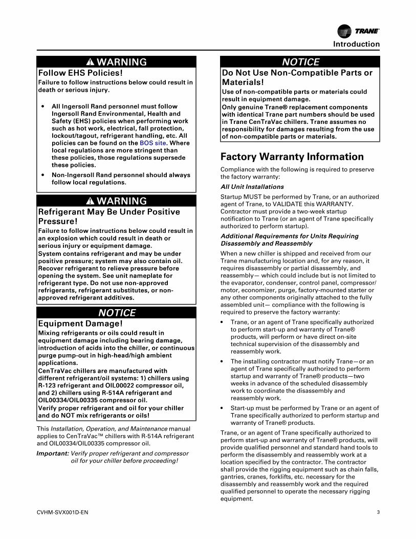
WWAARRNNIINNGGFFoollllooww EEHHSS PPoolliicciieess!!FFaaiilluurree ttoo ffoollllooww iinnssttrruuccttiioonnss bbeellooww ccoouulldd rreessuulltt iinnddeeaatthh oorr sseerriioouuss iinnjjuurryy..
•• AAllll IInnggeerrssoollll RRaanndd ppeerrssoonnnneell mmuusstt ffoolllloowwIInnggeerrssoollll RRaanndd EEnnvviirroonnmmeennttaall,, HHeeaalltthh aannddSSaaffeettyy ((EEHHSS)) ppoolliicciieess wwhheenn ppeerrffoorrmmiinngg wwoorrkkssuucchh aass hhoott wwoorrkk,, eelleeccttrriiccaall,, ffaallll pprrootteeccttiioonn,,lloocckkoouutt//ttaaggoouutt,, rreeffrriiggeerraanntt hhaannddlliinngg,, eettcc.. AAllllppoolliicciieess ccaann bbee ffoouunndd oonn tthhee BBOOSS ssiittee.. WWhheerreellooccaall rreegguullaattiioonnss aarree mmoorree ssttrriinnggeenntt tthhaanntthheessee ppoolliicciieess,, tthhoossee rreegguullaattiioonnss ssuuppeerrsseeddeetthheessee ppoolliicciieess..
•• NNoonn--IInnggeerrssoollll RRaanndd ppeerrssoonnnneell sshhoouulldd aallwwaayyssffoollllooww llooccaall rreegguullaattiioonnss..
WWAARRNNIINNGGRReeffrriiggeerraanntt MMaayy BBee UUnnddeerr PPoossiittiivveePPrreessssuurree!!FFaaiilluurree ttoo ffoollllooww iinnssttrruuccttiioonnss bbeellooww ccoouulldd rreessuulltt iinnaann eexxpplloossiioonn wwhhiicchh ccoouulldd rreessuulltt iinn ddeeaatthh oorrsseerriioouuss iinnjjuurryy oorr eeqquuiippmmeenntt ddaammaaggee..SSyysstteemm ccoonnttaaiinnss rreeffrriiggeerraanntt aanndd mmaayy bbee uunnddeerrppoossiittiivvee pprreessssuurree;; ssyysstteemm mmaayy aallssoo ccoonnttaaiinn ooiill..RReeccoovveerr rreeffrriiggeerraanntt ttoo rreelliieevvee pprreessssuurree bbeeffoorreeooppeenniinngg tthhee ssyysstteemm.. SSeeee uunniitt nnaammeeppllaattee ffoorrrreeffrriiggeerraanntt ttyyppee.. DDoo nnoott uussee nnoonn--aapppprroovveeddrreeffrriiggeerraannttss,, rreeffrriiggeerraanntt ssuubbssttiittuutteess,, oorr nnoonn--aapppprroovveedd rreeffrriiggeerraanntt aaddddiittiivveess..
NNOOTTIICCEEEEqquuiippmmeenntt DDaammaaggee!!MMiixxiinngg rreeffrriiggeerraannttss oorr ooiillss ccoouulldd rreessuulltt iinneeqquuiippmmeenntt ddaammaaggee iinncclluuddiinngg bbeeaarriinngg ddaammaaggee,,iinnttrroodduuccttiioonn ooff aacciiddss iinnttoo tthhee cchhiilllleerr,, oorr ccoonnttiinnuuoouussppuurrggee ppuummpp--oouutt iinn hhiigghh--hheeaadd//hhiigghh aammbbiieennttaapppplliiccaattiioonnss..CCeennTTrraaVVaacc cchhiilllleerrss aarree mmaannuuffaaccttuurreedd wwiitthhddiiffffeerreenntt rreeffrriiggeerraanntt//ooiill ssyysstteemmss:: 11)) cchhiilllleerrss uussiinnggRR--112233 rreeffrriiggeerraanntt aanndd OOIILL0000002222 ccoommpprreessssoorr ooiill,,aanndd 22)) cchhiilllleerrss uussiinngg RR--551144AA rreeffrriiggeerraanntt aannddOOIILL0000333344//OOIILL0000333355 ccoommpprreessssoorr ooiill..VVeerriiffyy pprrooppeerr rreeffrriiggeerraanntt aanndd ooiill ffoorr yyoouurr cchhiilllleerraanndd ddoo NNOOTT mmiixx rreeffrriiggeerraannttss oorr ooiillss!!
This Installation, Operation, and Maintenancemanualapplies to CenTraVac™ chillers with R-514A refrigerantand OIL00334/OIL00335 compressor oil.
IImmppoorrttaanntt:: Verify proper refrigerant and compressoroil for your chiller before proceeding!
NNOOTTIICCEEDDoo NNoott UUssee NNoonn--CCoommppaattiibbllee PPaarrttss oorrMMaatteerriiaallss!!UUssee ooff nnoonn--ccoommppaattiibbllee ppaarrttss oorr mmaatteerriiaallss ccoouullddrreessuulltt iinn eeqquuiippmmeenntt ddaammaaggee..OOnnllyy ggeennuuiinnee TTrraannee®® rreeppllaacceemmeenntt ccoommppoonneennttsswwiitthh iiddeennttiiccaall TTrraannee ppaarrtt nnuummbbeerrss sshhoouulldd bbee uusseeddiinn TTrraannee CCeennTTrraaVVaacc cchhiilllleerrss.. TTrraannee aassssuummeess nnoorreessppoonnssiibbiilliittyy ffoorr ddaammaaggeess rreessuullttiinngg ffrroomm tthhee uusseeooff nnoonn--ccoommppaattiibbllee ppaarrttss oorr mmaatteerriiaallss..
Factory Warranty InformationCompliance with the following is required to preservethe factory warranty:
AAllll UUnniitt IInnssttaallllaattiioonnss
Startup MUST be performed by Trane, or an authorizedagent of Trane, to VALIDATE this WARRANTY.Contractor must provide a two-week startupnotification to Trane (or an agent of Trane specificallyauthorized to perform startup).
AAddddiittiioonnaall RReeqquuiirreemmeennttss ffoorr UUnniittss RReeqquuiirriinnggDDiissaasssseemmbbllyy aanndd RReeaasssseemmbbllyy
When a new chiller is shipped and received from ourTrane manufacturing location and, for any reason, itrequires disassembly or partial disassembly, andreassembly— which could include but is not limited tothe evaporator, condenser, control panel, compressor/motor, economizer, purge, factory-mounted starter orany other components originally attached to the fullyassembled unit— compliance with the following isrequired to preserve the factory warranty:
• Trane, or an agent of Trane specifically authorizedto perform start-up and warranty of Trane®products, will perform or have direct on-sitetechnical supervision of the disassembly andreassembly work.
• The installing contractor must notify Trane—or anagent of Trane specifically authorized to performstartup and warranty of Trane® products—twoweeks in advance of the scheduled disassemblywork to coordinate the disassembly andreassembly work.
• Start-up must be performed by Trane or an agent ofTrane specifically authorized to perform startup andwarranty of Trane® products.
Trane, or an agent of Trane specifically authorized toperform start-up and warranty of Trane® products, willprovide qualified personnel and standard hand tools toperform the disassembly and reassembly work at alocation specified by the contractor. The contractorshall provide the rigging equipment such as chain falls,gantries, cranes, forklifts, etc. necessary for thedisassembly and reassembly work and the requiredqualified personnel to operate the necessary riggingequipment.
IInnttrroodduuccttiioonn
4 CVHM-SVX001D-EN
CopyrightThis document and the information in it are theproperty of Trane, and may not be used or reproducedin whole or in part without written permission. Tranereserves the right to revise this publication at any time,and to make changes to its content without obligationto notify any person of such revision or change.
TrademarksAll trademarks referenced in this document are thetrademarks of their respective owners.
Factory TrainingFactory training is available through Trane University™to help you learn more about the operation andmaintenance of your equipment. To learn aboutavailable training opportunities contact TraneUniversity™.
Online: www.trane.com/traneuniversity
Phone: 855-803-3563
Email: [email protected]
Revision History• Updated Installation Requirements section in
Electrical Requirements chapter.
• Added Determining Supply Ground Type section inPower Supply Wiring chapter.
• Updated the Chiller start-up tasks list to beperformed by Trane.
• Added Equipment Damage notice in Long TermUnit Storage, Operating Environment, StorageRequirements sections.
• Running edits.
IInnttrroodduuccttiioonn
CVHM-SVX001D-EN 5
Unit Nameplate. . . . . . . . . . . . . . . . . . . . . . . . . . . . . 8
Model Number Descriptions. . . . . . . . . . . . . . . 10
Pre-Installation . . . . . . . . . . . . . . . . . . . . . . . . . . . . 12ASHRAE Standard 15 Compliance . . . . . . . . 12
Unit Shipment. . . . . . . . . . . . . . . . . . . . . . . . . . . 12
Installation Requirements andContractor Responsibilities . . . . . . . . . . . . . . . 12
Storage Requirements . . . . . . . . . . . . . . . . . . . 14
Unit Components. . . . . . . . . . . . . . . . . . . . . . . . 15
Unit Clearances and Weights . . . . . . . . . . . . . . 17Recommended Unit Clearances. . . . . . . . . . . 17
General Weights. . . . . . . . . . . . . . . . . . . . . . . . . 18Weights (lb) . . . . . . . . . . . . . . . . . . . . . . . . . 18Weights (kg) . . . . . . . . . . . . . . . . . . . . . . . . . 18
Installation: Mechanical . . . . . . . . . . . . . . . . . . . 19Operating Environment . . . . . . . . . . . . . . . . . . 19
Foundation Requirements . . . . . . . . . . . . . . . . 19
Rigging . . . . . . . . . . . . . . . . . . . . . . . . . . . . . . . . . 19Standard Chiller Lift . . . . . . . . . . . . . . . . . . 19Special Lift Requirements. . . . . . . . . . . . . 20
Unit Isolation. . . . . . . . . . . . . . . . . . . . . . . . . . . . 21
Isolation Pads . . . . . . . . . . . . . . . . . . . . . . . . . . . 21
Spring Isolators . . . . . . . . . . . . . . . . . . . . . . . . . 21
Leveling the Unit . . . . . . . . . . . . . . . . . . . . . . . . 22
Installation: Water Piping . . . . . . . . . . . . . . . . . . 24Overview . . . . . . . . . . . . . . . . . . . . . . . . . . . . . . . 24
Water Treatment . . . . . . . . . . . . . . . . . . . . . . . . 24
Water Pressure Gauges . . . . . . . . . . . . . . . . . . 24
Valves—Drains and Vents . . . . . . . . . . . . . . . . 24
Strainers . . . . . . . . . . . . . . . . . . . . . . . . . . . . . . . . 25
Required Flow-Sensing Devices. . . . . . . . . . . 25Water Flow Detection Controller andSensor . . . . . . . . . . . . . . . . . . . . . . . . . . . . . . 25
Evaporator and Condenser WaterPiping . . . . . . . . . . . . . . . . . . . . . . . . . . . . . . . . . . 26
Water Piping Connections . . . . . . . . . . . . . . . . 28
Waterbox Locations . . . . . . . . . . . . . . . . . . . . . 28
Grooved Pipe Coupling . . . . . . . . . . . . . . . . . . 28
Flange-connection Adapters . . . . . . . . . . . . . . 29
Victaulic Gasket Installation . . . . . . . . . . . . . . 29
Screw-Tightening Sequence for WaterPiping Connections . . . . . . . . . . . . . . . . . . . . . . 30
Flanges with 8 or 12 Screws. . . . . . . . . . . 30Flanges with 16 Screws. . . . . . . . . . . . . . . 30
Pressure Testing Waterside Piping . . . . . . . . 31
Eddy Current Testing . . . . . . . . . . . . . . . . . . . . 31
Vent Piping . . . . . . . . . . . . . . . . . . . . . . . . . . . . . . . . 32Refrigerant Vent Line . . . . . . . . . . . . . . . . . . . . 32
General Requirements. . . . . . . . . . . . . . . . 32Purge Discharge . . . . . . . . . . . . . . . . . . . . . 32Vent Line Materials. . . . . . . . . . . . . . . . . . . 32Vent Line Sizing. . . . . . . . . . . . . . . . . . . . . . 32
Vent Line Installation. . . . . . . . . . . . . . . . . . . . . 33
Vent Line Sizing Reference . . . . . . . . . . . . . . . 36
Insulation. . . . . . . . . . . . . . . . . . . . . . . . . . . . . . . . . . 38Unit Insulation Requirements . . . . . . . . . . . . . 38
Insulation Thickness Requirements . . . . . . . 38Factory-applied Insulation . . . . . . . . . . . . 38
Installation: Controls . . . . . . . . . . . . . . . . . . . . . . 40UC800 Specifications . . . . . . . . . . . . . . . . . . . . 40
Power Supply. . . . . . . . . . . . . . . . . . . . . . . . 40Wiring and Port Descriptions. . . . . . . . . . 40Communication Interfaces . . . . . . . . . . . . 41Rotary Switches . . . . . . . . . . . . . . . . . . . . . 41LED Description and Operation. . . . . . . . 41
Installing the Tracer AdaptiViewDisplay . . . . . . . . . . . . . . . . . . . . . . . . . . . . . . . . . 44
Installing the Tracer AdaptiView Display—Alternate Location . . . . . . . . . . . . . . . . . . . . . 45
Adjusting the Tracer AdaptiView DisplayArm . . . . . . . . . . . . . . . . . . . . . . . . . . . . . . . . . . . . 45
Electrical Requirements . . . . . . . . . . . . . . . . . . . 46Installation Requirements . . . . . . . . . . . . . . . . 46
Electrical Requirements . . . . . . . . . . . . . . . . . . 46
Power Supply Wiring . . . . . . . . . . . . . . . . . . . . . . 48Three-Phase Power . . . . . . . . . . . . . . . . . . . . . . 48
Table of Contents
6 CVHM-SVX001D-EN
Circuit Breakers and FusedDisconnects . . . . . . . . . . . . . . . . . . . . . . . . . . . . . 48
Installing AFD Input Power WiringStandard Cabinet . . . . . . . . . . . . . . . . . . . . . . . . 48
Torquing Electrical PowerConnections . . . . . . . . . . . . . . . . . . . . . . . . . 49Cabinet Wire Routing. . . . . . . . . . . . . . . . . 49Grounding the Cabinet . . . . . . . . . . . . . . . 49Determining Supply GroundType . . . . . . . . . . . . . . . . . . . . . . . . . . . . . . . . 50
System Control Circuit Wiring (FieldWiring) . . . . . . . . . . . . . . . . . . . . . . . . . . . . . . . . . . . . 51
Sensor Circuits . . . . . . . . . . . . . . . . . . . . . . . . . . 54CWR—Outdoor Option . . . . . . . . . . . . . . . 56Optional Control and OutputCircuits. . . . . . . . . . . . . . . . . . . . . . . . . . . . . . 56Optional Tracer CommunicationInterface . . . . . . . . . . . . . . . . . . . . . . . . . . . . 56
Controls System. . . . . . . . . . . . . . . . . . . . . . . . . 57
Schematic Wiring Drawings . . . . . . . . . . . . . . 57
Operating Principles . . . . . . . . . . . . . . . . . . . . . . . 58General Requirements . . . . . . . . . . . . . . . . . . . 58
Cooling Cycle . . . . . . . . . . . . . . . . . . . . . . . . . . . 58CVHM Compressor. . . . . . . . . . . . . . . . . . . 58
Oil and Refrigerant Pump . . . . . . . . . . . . . . . . 58Compressor LubricationSystem. . . . . . . . . . . . . . . . . . . . . . . . . . . . . . 58
Tracer AdaptiView Display . . . . . . . . . . . . . . . 60
Adaptive Frequency Drive . . . . . . . . . . . . . . . . 60Introduction . . . . . . . . . . . . . . . . . . . . . . . . . 60UC800 Adaptive Frequency DriveControl. . . . . . . . . . . . . . . . . . . . . . . . . . . . . . 60AFD Cooling Circuit . . . . . . . . . . . . . . . . . . 63
Start-up and Shut-down . . . . . . . . . . . . . . . . . . . 65Sequence of Operation. . . . . . . . . . . . . . . . . . . 65
Software Operation OverviewDiagram. . . . . . . . . . . . . . . . . . . . . . . . . . . . . 65Start-up Sequence of Operation . . . . . . . 66Power Up . . . . . . . . . . . . . . . . . . . . . . . . . . . 69
Hot Water Control . . . . . . . . . . . . . . . . . . . . . . . 69
Control Panel Devices and Unit-MountedDevices . . . . . . . . . . . . . . . . . . . . . . . . . . . . . . . . . 70
Unit Control Panel . . . . . . . . . . . . . . . . . . . 70User-defined Language Support . . . . . . 70
Unit Start-up and Shut-downProcedures. . . . . . . . . . . . . . . . . . . . . . . . . . . . . . 70
Daily Unit Start-up . . . . . . . . . . . . . . . . . . . 71Seasonal Unit Start-up . . . . . . . . . . . . . . . 71Daily Unit Shut-down . . . . . . . . . . . . . . . . 72Seasonal Unit Shut-down. . . . . . . . . . . . . 72
Recommended Maintenance . . . . . . . . . . . . . . 73Record Keeping Forms . . . . . . . . . . . . . . . . . . . 73
Normal Operation . . . . . . . . . . . . . . . . . . . . . . . 73
Recommended Compressor OilChange . . . . . . . . . . . . . . . . . . . . . . . . . . . . . . . . . 75
Purge System . . . . . . . . . . . . . . . . . . . . . . . . . . . 75Leak Checking Based on Purge PumpOut Time . . . . . . . . . . . . . . . . . . . . . . . . . . . . 76
Long Term Unit Storage. . . . . . . . . . . . . . . . . . 76
Refrigerant Charge . . . . . . . . . . . . . . . . . . . . . . 76
Leak Testing . . . . . . . . . . . . . . . . . . . . . . . . . . . . 77
Recommended SystemMaintenance . . . . . . . . . . . . . . . . . . . . . . . . . . . . 77
Condenser . . . . . . . . . . . . . . . . . . . . . . . . . . 77Evaporator . . . . . . . . . . . . . . . . . . . . . . . . . . 78Waterbox and Tubesheet ProtectiveCoatings . . . . . . . . . . . . . . . . . . . . . . . . . . . . 78Sacrificial Anodes. . . . . . . . . . . . . . . . . . . . 78
Adaptive Frequency Drive . . . . . . . . . . . . . . . . 78Visual Inspection—PowerRemoved. . . . . . . . . . . . . . . . . . . . . . . . . . . . 78Drive Cooling Fluid ServiceIntervals. . . . . . . . . . . . . . . . . . . . . . . . . . . . . 79Operational Inspection—PowerApplied . . . . . . . . . . . . . . . . . . . . . . . . . . . . . 79
Waterbox Removal and Installation . . . . . . . 81Discussion . . . . . . . . . . . . . . . . . . . . . . . . . . . . . . 81
Procedure. . . . . . . . . . . . . . . . . . . . . . . . . . . . . . . 81Reassembly . . . . . . . . . . . . . . . . . . . . . . . . . 82Torque Requirements and WaterboxWeights . . . . . . . . . . . . . . . . . . . . . . . . . . . . . 82
Connection Devices Information . . . . . . . . . . 83
Screw-Tightening Sequence forWaterboxes . . . . . . . . . . . . . . . . . . . . . . . . . . . . . 83
TTaabbllee ooff CCoonntteennttss
CVHM-SVX001D-EN 7
Evaporator Waterbox Covers . . . . . . . . . 83Condenser Waterbox Covers. . . . . . . . . . 83
Adaptive Frequency Drive Removal andInstallation . . . . . . . . . . . . . . . . . . . . . . . . . . . . . . . . 84
Factory Warranty Information . . . . . . . . . . . . 84
Cabinet Dimensions . . . . . . . . . . . . . . . . . . . . . 85
Cabinet Removal . . . . . . . . . . . . . . . . . . . . . . . . 85
Appendix A: Forms and CheckSheets . . . . . . . . . . . . . . . . . . . . . . . . . . . . . . . . . . . . . 88
Unit Start-up/Commissioning. . . . . . . . . . . . . 88
Appendix B: CenTraVac™ Chiller InstallationCompletion and Request for TraneService . . . . . . . . . . . . . . . . . . . . . . . . . . . . . . . . . . . . 89
Appendix C: CVHM CenTraVac™ ChillerStart-up Tasks to be Performed byTrane . . . . . . . . . . . . . . . . . . . . . . . . . . . . . . . . . . . . . . 91
Appendix D: CVHM CenTraVac™ ChillerAnnual Inspection List . . . . . . . . . . . . . . . . . . . . . 93
Appendix E: CVHM CenTraVac™ ChillerOperator Log . . . . . . . . . . . . . . . . . . . . . . . . . . . . . . 94
TTaabbllee ooff CCoonntteennttss
8 CVHM-SVX001D-EN
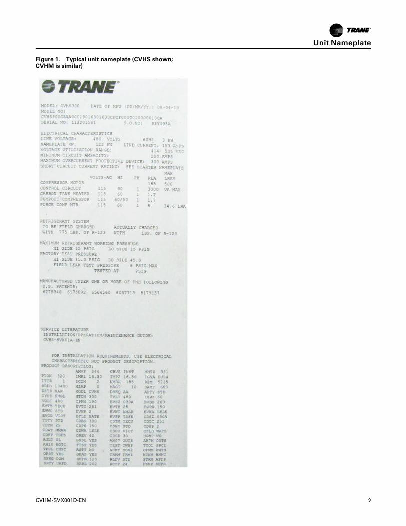
Unit Nameplate
The unit nameplate is located on the right side of thecontrol panel. A typical unit nameplate is illustrated inthe following figure and contains the followinginformation:
• Unit model and size descriptor
• Unit electrical requirements
• Correct operating charge and refrigerant type
• Unit test pressures and maximum operatingpressures
• Unit literature
SSeerriiaall NNuummbbeerr.. The unit serial number provides thespecific chiller identity. Always provide this serialnumber when calling for service or during partsidentification.
SSeerrvviiccee MMooddeell NNuummbbeerr.. The service model representsthe unit as built for service purposes. It identifies theselections of variable unit features required whenordering replacements parts or requesting service.
NNoottee:: Unit-mounted Adaptive Frequency™ Drives(AFDs) are identified by a separate numberfound on the AFD.
PPrroodduucctt DDeessccrriippttiioonn BBlloocckk.. The CenTraVac™ chillermodels are defined and built using the ProductDefinition and Selection (PDS) system. This systemdescribes the product offerings using a product codingblock which is made up of feature categories and codesthat identify all characteristics of a unit.
CVHM-SVX001D-EN 9
Figure 1. Typical unit nameplate (CVHS shown;CVHM is similar)
UUnniitt NNaammeeppllaattee
10 CVHM-SVX001D-EN
Model Number Descriptions
Digit 1, 2 — Unit Function
CV = CenTraVac™ Hermetic Chiller
Digit 3 — Drive
H = Direct Drive
Digit 4 — Development Sequence
M
Digit 5, 6, 7 — Nominal CompressorTonnage300 = 300 Nominal TonsSSS = Special
Digit 8 — Unit Motor Voltage
D = 380V-60HzE = 440V-60HzF = 460V-60HzG = 480V-60HzR = 380V-50HzT = 400V-50HzU = 415V-50HzS = Special
Digit 9 — Unit Type
A = Cooling CondenserS = Special
Digit 10, 11— Design Sequence
AA = Original Design
Digit 12— Hot Gas Bypass
0 =Without HGBS = Special
Digit 13— Control Enclosure
C = Standard Control EnclosureD = Standard Control Enclosure with Tracer®SCS = Special
Digit 14, 15, 16, 17— CompressorMotor Power (kW) (See Note 1)0210 = 210 CPKW
Digit 18, 19, 20, 21— CompressorImpeller Cutback Stage 1 (See Note2)1540 = 15.40-in. DiameterSSSS = Special
Digit 22, 23, 24, 25— CompressorImpeller Cutback Stage 2 (See Note3)1620 = 16.20-in. DiameterSSSS = Special
Digit 26 — Evaporator Shell Size
C= 300-Ton Short Evaporator Shell (030A)D = 300-Ton Long Evaporator Shell (030B)S = Special
Digit 27 — EvaporatorWaterbox
A = 150 psi Marine, 1-Pass StdB = 150 psi Marine, 2-Pass StdC= 300 psi Marine, 1-Pass StdD = 300 psi Marine, 2-Pass StdE= 150 psi Non-Marine, 1-Pass StdF= 150 psi Non-Marine, 2-Pass StdG = 300 psi Non-Marine, 1-Pass StdH= 300 psi Non-Marine, 2-Pass StdS = Special
Digit 28 — Condenser Shell Size
C= 300-Ton Short Condenser Shell (030A)D = 300-Ton Long Condenser Shell (030B)S = Special
Digit 29 — CondenserWaterbox
A = 150 psi Marine, 1-Pass StdB = 150 psi Marine, 2-Pass StdC= 300 psi Marine, 1-Pass StdD = 300 psi Marine, 2-Pass StdE= 150 psi Non-Marine, 1-Pass StdF= 150 psi Non-Marine, 2-Pass StdG = 300 psi Non-Marine, 1-Pass StdH= 300 psi Non-Marine, 2-Pass StdS = Special
Digit 30 —Heat Recovery CondenserWaterbox0 = NoneS = Special
Digit 31 — Auxiliary Condenser SizeandWaterbox0 = NoneS = Special
Digit 32 —Unit Option
0 = NoneA = Insulation Package OnlyB = Insulation Package and 3-in.RuptureGuard™C= Insulation Package and 4-in.RuptureGuardD = 3-in. RuptureGuard™ OnlyE= 4-in. RuptureGuard™ OnlyF= Extra-thick Insulation and 3-in.RuptureGuard™G = Extra-thick Insulation and 4-in.RuptureGuard™H= Extra-thick Insulation Only
Digit 33— Control: Generic BAS
0 = NoneG = Generic BAS
Digit 34— Control: ExtendedOperation0 = None1 = Extended Operation
Digit 35— Tracer®® CommunicationInterface0 = None1 = Tracer® Comm 42 = Tracer® Comm 53 = Tracer®MODBUS®4 = Tracer® BACnet®
Digit 36— Control: CondenserRefrigerant Pressure0 = NoneC = Condenser Refrigerant Pressure
Digit 37— Special Options
0 = NoneS = Special Option
Digit 38— Control: Water FlowControl0 = NoneW =Water Flow Control
Digit 39— Control: ChilledWaterReset0 = None1 = Chilled Water Reset
Digit 40— Control: Heat RecoveryTemperature Sensors0 = None
Digit 41— Control: Operating Status
0 = None1 = Operating Status
Digit 42— Industrial Chiller Package(INDP)0 =Without INDP
Digit 43— Control Power Transformer(CPTR)0 =Without CPTRS = Special
CVHM-SVX001D-EN 11
Digit 44— Thermal DispersionWaterFlow Proving0 = None, Customer to Provide Device forCondenser and EvaporatorA = Thermal Dispersion Water Flow ProvingSelected for Condenser and EvaporatorB = Thermal Dispersion Water Flow ProvingSelected for Condenser OnlyC = Thermal Dispersion Water Flow ProvingSelected for Evaporator Only
Digit 45—Manufacturing Location
L = La Crosse, WisconsinT = Taicang, China
Model Number NotesNotes:
1. Digits 14–17 represents the actual CPKW value; if the CPKW is only three digits, digit 14 is “0.”2. Cutbacks are done in 0.40-in. dimensions; i.e., if digits 18–21 = 1540, the cutback diameter is 15.40.3. Cutbacks are done in 0.40-in. dimensions; i.e., if digits 22–25 = 1620, the cutback diameter is 16.20.
MMooddeell NNuummbbeerr DDeessccrriippttiioonnss
12 CVHM-SVX001D-EN
Pre-InstallationASHRAE Standard 15ComplianceTrane recommends that indoor CenTraVac™ chillerinstallations fully meet or exceed the guidelines of thecurrent version of ASHRAE Standard 15, in addition toany applicable national, state, or local requirements.This typically includes:
• A refrigerant monitor or detector that is capable ofmonitoring and alarming within the acceptableexposure level of the refrigerant, and that canactuate mechanical ventilation.
• Audible and visual alarms, activated by therefrigerant monitor, inside the equipment room andoutside of every entrance.
• The equipment room should be properly vented tothe outdoors, using mechanical ventilation that canbe activated by the refrigerant monitor.
• The purge discharge and the rupture disk must beproperly piped to the outdoors.
• If required by local or other codes, a self-containedbreathing apparatus should be available in closeproximity to the equipment room.
Refer to the latest copy of ASHRAE Standard 15 forspecific guidelines. Trane assumes no responsibility forany economic, health, or environmental issues thatmay result from an equipment room’s design orfunction.
Unit ShipmentInspect unit while it is still on the truck for any shippingdamage. The chiller ships shrink-wrapped in a 0.010-in.(0.254 mm) recyclable film protective covering. Do NOTremove shrink-wrap for inspection! Inspect for damageto the shrink-wrap and determine if physical damagehas occurred.
Each chiller ships from the factory as a hermeticallyassembled package; it is factory-assembled, -wired,and -tested. All openings except for the waterbox ventand drain holes are covered or plugged to preventcontamination during shipment and handling.“UnitComponents,” p. 15 shows an illustration of a typicalunit and its components. As soon as the unit arrives atthe job site, inspect it thoroughly for damage andmaterial shortages. In addition:
1. Verify the hermetic integrity of the unit by checkingthe chiller pressure for an indication of holdingcharge pressure.
2. To prevent damaging moisture from entering theunit and causing corrosion, each chiller ispressurized with 3 to 5 psig (20.7 to 34.5 kPaG) ofdry nitrogen before shipment.
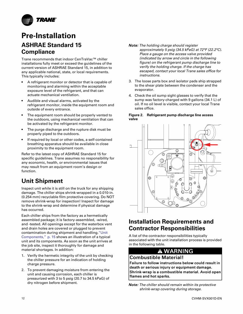
NNoottee:: The holding charge should registerapproximately 5 psig (34.5 kPaG) at 72°F (22.2°C).Place a gauge on the access valve provided(indicated by arrow and circle in the followingfigure) on the refrigerant pump discharge line toverify the holding charge. If the charge hasescaped, contact your local Trane sales office forinstructions.
3. The loose parts box and isolator pads ship strappedto the shear plate between the condenser and theevaporator.
4. Check the oil sump sight glasses to verify that thesump was factory-charged with 9 gallons (34.1 L) ofoil. If no oil level is visible, contact your local Tranesales office.
Figure 2. Refrigerant pump discharge line accessvalve
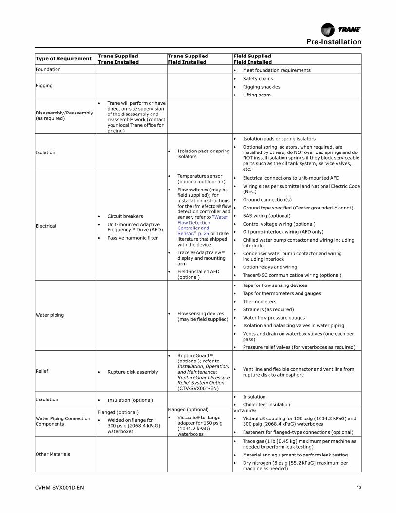
Installation Requirements andContractor ResponsibilitiesA list of the contractor responsibilities typicallyassociated with the unit installation process is providedin the following table.
WWAARRNNIINNGGCCoommbbuussttiibbllee MMaatteerriiaall!!FFaaiilluurree ttoo ffoollllooww iinnssttrruuccttiioonnss bbeellooww ccoouulldd rreessuulltt iinnddeeaatthh oorr sseerriioouuss iinnjjuurryy oorr eeqquuiippmmeenntt ddaammaaggee..SShhrriinnkk--wwrraapp iiss aa ccoommbbuussttiibbllee mmaatteerriiaall.. AAvvooiidd ooppeennffllaammeess aanndd hhoott ssppaarrkkss..
NNoottee:: The chiller should remain within its protectiveshrink-wrap covering during storage.
CVHM-SVX001D-EN 13
Type of Requirement Trane SuppliedTrane Installed
Trane SuppliedField Installed
Field SuppliedField Installed
Foundation • Meet foundation requirements
Rigging• Safety chains
• Rigging shackles
• Lifting beam
Disassembly/Reassembly(as required)
• Trane will perform or havedirect on-site supervisionof the disassembly andreassembly work (contactyour local Trane office forpricing)
Isolation • Isolation pads or springisolators
• Isolation pads or spring isolators
• Optional spring isolators, when required, areinstalled by others; do NOToverload springs and doNOT install isolation springs if they block serviceableparts such as the oil tank system, service valves,etc.
Electrical
• Circuit breakers
• Unit-mounted AdaptiveFrequency™ Drive (AFD)
• Passive harmonic filter
• Temperature sensor(optional outdoor air)
• Flow switches (may befield supplied); forinstallation instructionsfor the ifm efector® flowdetection controller andsensor, refer to “WaterFlow DetectionController andSensor,” p. 25 or Traneliterature that shippedwith the device
• Tracer® AdaptiView™display and mountingarm
• Field-installed AFD(optional)
• Electrical connections to unit-mounted AFD
• Wiring sizes per submittal and National Electric Code(NEC)
• Ground connection(s)
• Ground type specified (Center grounded-Y or not)
• BAS wiring (optional)
• Control voltage wiring (optional)
• Oil pump interlock wiring (AFD only)
• Chilled water pump contactor and wiring includinginterlock
• Condenser water pump contactor and wiringincluding interlock
• Option relays and wiring
• Tracer® SC communication wiring (optional)
Water piping • Flow sensing devices(may be field supplied)
• Taps for flow sensing devices
• Taps for thermometers and gauges
• Thermometers
• Strainers (as required)
• Water flow pressure gauges
• Isolation and balancing valves in water piping
• Vents and drain on waterbox valves (one each perpass)
• Pressure relief valves (for waterboxes as required)
Relief • Rupture disk assembly
• RuptureGuard™(optional); refer toInstallation, Operation,and Maintenance:RuptureGuard PressureRelief System Option(CTV-SVX06*-EN)
• Vent line and flexible connector and vent line fromrupture disk to atmosphere
Insulation • Insulation (optional)• Insulation
• Chiller feet insulation
Water Piping ConnectionComponents
Flanged (optional)
• Welded on flange for300 psig (2068.4 kPaG)waterboxes
Flanged (optional)
• Victaulic® to flangeadapter for 150 psig(1034.2 kPaG)waterboxes
Victaulic®
• Victaulic® coupling for 150 psig (1034.2 kPaG) and300 psig (2068.4 kPaG) waterboxes
• Fasteners for flanged-type connections (optional)
Other Materials
• Trace gas (1 lb [0.45 kg] maximum per machine asneeded to perform leak testing)
• Material and equipment to perform leak testing
• Dry nitrogen (8 psig [55.2 kPaG] maximum permachine as needed)
PPrree--IInnssttaallllaattiioonn
14 CVHM-SVX001D-EN
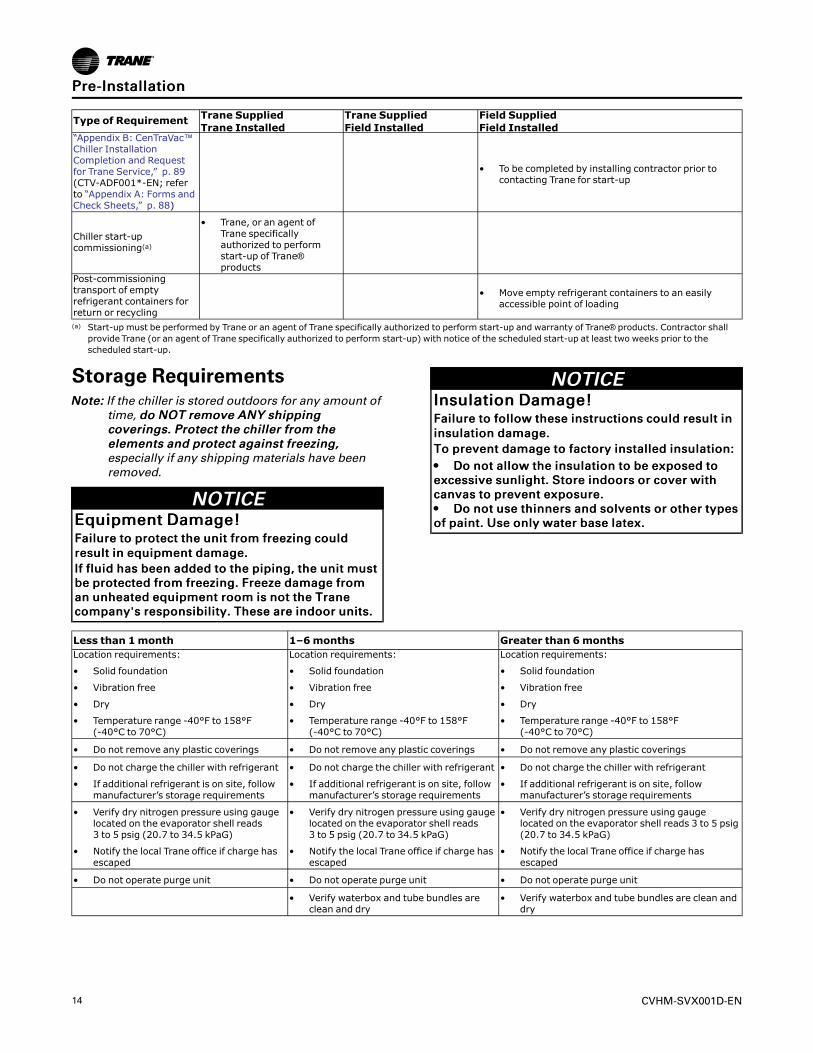
Type of Requirement Trane SuppliedTrane Installed
Trane SuppliedField Installed
Field SuppliedField Installed
“Appendix B: CenTraVac™Chiller InstallationCompletion and Requestfor Trane Service,” p. 89(CTV-ADF001*-EN; referto “Appendix A: Forms andCheck Sheets,” p. 88)
• To be completed by installing contractor prior tocontacting Trane for start-up
Chiller start-upcommissioning(a)
• Trane, or an agent ofTrane specificallyauthorized to performstart-up of Trane®products
Post-commissioningtransport of emptyrefrigerant containers forreturn or recycling
• Move empty refrigerant containers to an easilyaccessible point of loading
(a) Start-up must be performed by Trane or an agent of Trane specifically authorized to perform start-up and warranty of Trane® products. Contractor shallprovide Trane (or an agent of Trane specifically authorized to perform start-up) with notice of the scheduled start-up at least two weeks prior to thescheduled start-up.
Storage RequirementsNNoottee:: If the chiller is stored outdoors for any amount of
time, ddoo NNOOTT rreemmoovvee AANNYY sshhiippppiinnggccoovveerriinnggss.. PPrrootteecctt tthhee cchhiilllleerr ffrroomm tthheeeelleemmeennttss aanndd pprrootteecctt aaggaaiinnsstt ffrreeeezziinngg,,especially if any shipping materials have beenremoved.
NNOOTTIICCEEEEqquuiippmmeenntt DDaammaaggee!!FFaaiilluurree ttoo pprrootteecctt tthhee uunniitt ffrroomm ffrreeeezziinngg ccoouullddrreessuulltt iinn eeqquuiippmmeenntt ddaammaaggee..IIff fflluuiidd hhaass bbeeeenn aaddddeedd ttoo tthhee ppiippiinngg,, tthhee uunniitt mmuussttbbee pprrootteecctteedd ffrroomm ffrreeeezziinngg.. FFrreeeezzee ddaammaaggee ffrroommaann uunnhheeaatteedd eeqquuiippmmeenntt rroooomm iiss nnoott tthhee TTrraanneeccoommppaannyy''ss rreessppoonnssiibbiilliittyy.. TThheessee aarree iinnddoooorr uunniittss..
NNOOTTIICCEEIInnssuullaattiioonn DDaammaaggee!!FFaaiilluurree ttoo ffoollllooww tthheessee iinnssttrruuccttiioonnss ccoouulldd rreessuulltt iinniinnssuullaattiioonn ddaammaaggee..TToo pprreevveenntt ddaammaaggee ttoo ffaaccttoorryy iinnssttaalllleedd iinnssuullaattiioonn::•• DDoo nnoott aallllooww tthhee iinnssuullaattiioonn ttoo bbee eexxppoosseedd ttooeexxcceessssiivvee ssuunnlliigghhtt.. SSttoorree iinnddoooorrss oorr ccoovveerr wwiitthhccaannvvaass ttoo pprreevveenntt eexxppoossuurree..•• DDoo nnoott uussee tthhiinnnneerrss aanndd ssoollvveennttss oorr ootthheerr ttyyppeessooff ppaaiinntt.. UUssee oonnllyy wwaatteerr bbaassee llaatteexx..
Less than 1month 1–6months Greater than 6monthsLocation requirements:
• Solid foundation
• Vibration free
• Dry
• Temperature range -40°F to 158°F(-40°C to 70°C)
Location requirements:
• Solid foundation
• Vibration free
• Dry
• Temperature range -40°F to 158°F(-40°C to 70°C)
Location requirements:
• Solid foundation
• Vibration free
• Dry
• Temperature range -40°F to 158°F(-40°C to 70°C)
• Do not remove any plastic coverings • Do not remove any plastic coverings • Do not remove any plastic coverings
• Do not charge the chiller with refrigerant
• If additional refrigerant is on site, followmanufacturer’s storage requirements
• Do not charge the chiller with refrigerant
• If additional refrigerant is on site, followmanufacturer’s storage requirements
• Do not charge the chiller with refrigerant
• If additional refrigerant is on site, followmanufacturer’s storage requirements
• Verify dry nitrogen pressure using gaugelocated on the evaporator shell reads3 to 5 psig (20.7 to 34.5 kPaG)
• Notify the local Trane office if charge hasescaped
• Verify dry nitrogen pressure using gaugelocated on the evaporator shell reads3 to 5 psig (20.7 to 34.5 kPaG)
• Notify the local Trane office if charge hasescaped
• Verify dry nitrogen pressure using gaugelocated on the evaporator shell reads 3 to 5 psig(20.7 to 34.5 kPaG)
• Notify the local Trane office if charge hasescaped
• Do not operate purge unit • Do not operate purge unit • Do not operate purge unit
• Verify waterbox and tube bundles areclean and dry
• Verify waterbox and tube bundles are clean anddry
PPrree--IInnssttaallllaattiioonn
CVHM-SVX001D-EN 15
Less than 1month 1–6months Greater than 6months
• Conduct an oil analysis and verify no oilbreakdown(a)
• Repeat yearly
• Replace oil if breakdown has occurred
• If no oil analysis program has been followed,replace oil prior to start-up
• Every six months, check unit pressure orvacuum and take note of changes that couldindicate a leak; contact your local Trane office ifany leaks occur
• If the chiller will be stored for more thansix months after production, contact your localTrane Service Agency for required extendedstorage actions to minimize impact to the chillerand preserve the warranty.
• Chillers stored five years or longer should beinspected for leaks every five years by aqualified service organization
(a) If the chiller will be stored for more than six months after production, contact your local Trane Service Agency for required extended storage actions tominimize impact to the chiller and preserve the warranty.
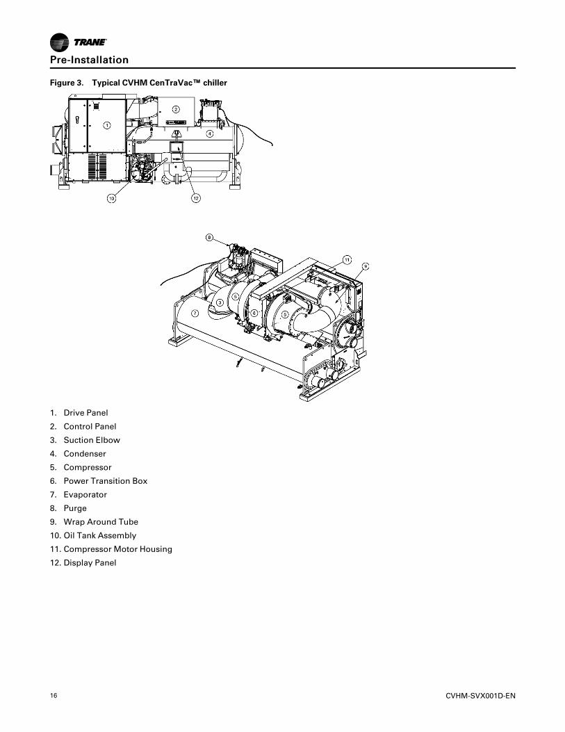
Unit ComponentsNNoottee:: The control panel side of the unit is always
designated as the front side of the unit.
PPrree--IInnssttaallllaattiioonn
16 CVHM-SVX001D-EN
Figure 3. Typical CVHM CenTraVac™™ chiller
1. Drive Panel
2. Control Panel
3. Suction Elbow
4. Condenser
5. Compressor
6. Power Transition Box
7. Evaporator
8. Purge
9. Wrap Around Tube
10. Oil Tank Assembly
11. Compressor Motor Housing
12. Display Panel
PPrree--IInnssttaallllaattiioonn
CVHM-SVX001D-EN 17
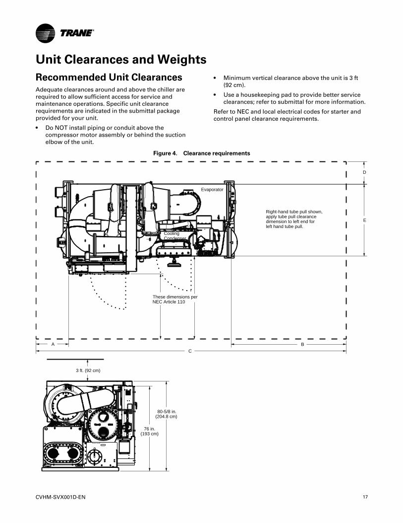
Unit Clearances and WeightsRecommended Unit ClearancesAdequate clearances around and above the chiller arerequired to allow sufficient access for service andmaintenance operations. Specific unit clearancerequirements are indicated in the submittal packageprovided for your unit.
• Do NOT install piping or conduit above thecompressor motor assembly or behind the suctionelbow of the unit.
• Minimum vertical clearance above the unit is 3 ft(92 cm).
• Use a housekeeping pad to provide better serviceclearances; refer to submittal for more information.
Refer to NEC and local electrical codes for starter andcontrol panel clearance requirements.
Figure 4. Clearance requirements
76 in. (193 cm)
80-5/8 in.(204.8 cm)
3 ft. (92 cm)
B
D
E
These dimensions per NEC Article 110
A C
Evaporator
CoolingCondenser
Right-hand tube pull shown,apply tube pull clearance dimension to left end for left hand tube pull.
18 CVHM-SVX001D-EN
Table 1. Clearance requirements
EVSZ CDSZA B C D(a) E
in. cm in. cm in. cm in. cm in. cm
030A 030A 46.26 117.50 156 396.24 353.75 898.53 20 50.8 70 177.8
030B 030B 46.26 117.50 186 472.44 413.75 1050.93 20 50.8 70 177.8Notes:
1. All dimensions are approximate; refer to the unit submittal package for exact dimensions for your unit.2. Determine bundle size by looking at unit nameplate. EVSZ is evaporator size and CVSZ is condenser size; A is short and B is long.
(a) 20-in. clearance is required for routine maintenance and housekeeping. Compressor service will require additional space either at the back of the chiller oroverhead.
General WeightsWeights (lb)IImmppoorrttaanntt:: The weight information provided here
should be used for general informationonly. For specific weights for your chiller,refer to your submittal package.
Table 2. Representative weights, 60 Hz chillers (lb)
ModelComp Size
CPKWEvap Size Cond Size Weights without Starters Weights with Starters
NTON EVSZ CDSZ Operating Shipping Operating Shipping
CVHM300 210 030A 030A — — 22430 19870
300 210 030B 030B — — 23822 20931
Notes:1. TECU tubes, 0.028 in. tube wall thickness.2. 300 psig marine waterboxes.3. Heaviest possible bundle and motor combination.4. Operating weights assume the largest possible refrigerant charge.5. Weights with starters assume the heaviest possible starter (AFD when it’s an allowed option).6. Industrial Control Panel (INDP) option, add 50 lb.7. Control Power Transformer (CPTR) option, add 130 lb.8. Supplemental Motor Protection (SMP) option, add 500 lb.
Weights (kg)IImmppoorrttaanntt:: The weight information provided here
should be used for general informationonly. For specific weights for your chiller,refer to your submittal package.
Table 3. Representative weights, 60 Hz chillers (kg)
ModelComp Size
CPKWEvap Size Cond Size Weights without Starters Weights with Starters
NTON EVSZ CDSZ Operating Shipping Operating Shipping
CVHM300 210 030A 030A — — 10111 8950
300 210 030B 030B — — 10742 9431
Notes:1. TECU tubes, 0.71 mm tube wall thickness.2. 2068.4 kPaG non-marine waterboxes.3. Heaviest possible bundle and motor combination.4. Operating weights assume the largest possible refrigerant charge.5. Weights with starters assume the heaviest possible starter (AFD when it’s an allowed option).6. Industrial Control Panel (INDP) option, add 23 kg.7. Control Power Transformer (CPTR) option, add 59 kg.8. Supplemental Motor Protection (SMP) option, add 227 kg.
UUnniitt CClleeaarraanncceess aanndd WWeeiigghhttss
CVHM-SVX001D-EN 19
Installation: MechanicalOperating EnvironmentIImmppoorrttaanntt::
• The standard chiller is designed forINDOOR USE ONLY and as such hasNEMA Type 1 enclosures.
• For chillers in unheated equipmentrooms, contact your local Trane ServiceAgency for methods to ensure that theoil temperature is maintained suitablefor proper operation of the chiller.
NNOOTTIICCEEEEqquuiippmmeenntt DDaammaaggee!!FFaaiilluurree ttoo pprrootteecctt tthhee uunniitt ffrroomm ffrreeeezziinngg ccoouullddrreessuulltt iinn eeqquuiippmmeenntt ddaammaaggee..IIff fflluuiidd hhaass bbeeeenn aaddddeedd ttoo tthhee ppiippiinngg,, tthhee uunniitt mmuussttbbee pprrootteecctteedd ffrroomm ffrreeeezziinngg.. FFrreeeezzee ddaammaaggee ffrroommaann uunnhheeaatteedd eeqquuiippmmeenntt rroooomm iiss nnoott tthhee TTrraanneeccoommppaannyy''ss rreessppoonnssiibbiilliittyy.. TThheessee aarree iinnddoooorr uunniittss..
NNOOTTIICCEEEEqquuiippmmeenntt FFaaiilluurree!!UUnniitt ooppeerraattiinngg aatt aammbbiieenntt tteemmppeerraattuurreess eexxcceeeeddiinngg110044°°FF ((4400°°CC)) ccoouulldd rreessuulltt iinn AAFFDD//ssttaarrtteerrccoommppoonneenntt ddaammaaggee dduuee ttoo tthhee ppaanneell’’ss iinnaabbiilliittyy ttooddiissssiippaattee hheeaatt aaddeeqquuaatteellyy.. FFoorr CCDDHHFF,, CCDDHHGG,, CCVVHHEE,,CCVVHHFF,, CCVVHHGG,, CCVVHHLL,, CCVVHHMM,, aanndd CCVVHHSS CCeennTTrraaVVaacccchhiilllleerrss,, uunniittss ooppeerraattiinngg aatt tthheessee tteemmppeerraattuurreessccoouulldd aallssoo ffaattiigguuee tthhee uunniitt’’ss rruuppttuurree ddiisskk,, ccaauussiinnggiitt ttoo bbrreeaakk aatt aa rreedduucceedd rreeffrriiggeerraanntt pprreessssuurree ((<<1155ppssiigg [[<<110033..44 kkPPaaGG]]))..IIff aannyy ooff tthheessee aaddvveerrssee ooppeerraattiinngg ccoonnddiittiioonnss aarreepprreesseenntt,, ttaakkee nneecceessssaarryy aaccttiioonn ttoo iimmpprroovvee tthheeeeqquuiippmmeenntt rroooomm eennvviirroonnmmeenntt..
To ensure that electrical components operate properly,do NOT locate the chiller in an area exposed to dust,dirt, corrosive fumes, or excessive heat and humidity.The ambient temperature range for chiller operation is34°F to 104°F (1.1°C to 40°C).
Foundation RequirementsChiller mounting surface must be:
• rigid non-warping mounting pads or a concretefoundation, and
• able to support the chiller at its full operatingweight (including completed piping and fulloperating charges of refrigerant, oil, and water).
For proper unit operation, the chiller must be levelwithin 1/16 in. (1.6 mm) over its length and width whenset into place on the mounting surface. Refer to“Leveling the Unit,” p. 22 for more information. Forapproximate weights for various chiller sizes and
options in pounds and kilograms, refer to “Weights(lb),” p. 18 and “Weights (kg),” p. 18, respectively.
NNoottee:: For specific weight information, refer to the unitsubmittal package.
IImmppoorrttaanntt:: Trane will not assume responsibility forequipment problems resulting from animproperly designed or constructedfoundation.
RiggingLifting is the recommended method for movingchillers. Suggested lifting arrangements for standardunits are described in “Standard Chiller Lift,” p. 19.
NNoottee:: The lifting beam used for CVHM CenTraVac™chillers must be at least 12.5 ft (3.8 m) long.
WWAARRNNIINNGGHHeeaavvyy OObbjjeecctt!!FFaaiilluurree ttoo ffoollllooww iinnssttrruuccttiioonnss bbeellooww ccoouulldd rreessuulltt iinnuunniitt ddrrooppppiinngg wwhhiicchh ccoouulldd rreessuulltt iinn ddeeaatthh oorrsseerriioouuss iinnjjuurryy,, aanndd eeqquuiippmmeenntt oorr pprrooppeerrttyy--oonnllyyddaammaaggee..EEnnssuurree tthhaatt aallll tthhee lliiffttiinngg eeqquuiippmmeenntt uusseedd iisspprrooppeerrllyy rraatteedd ffoorr tthhee wweeiigghhtt ooff tthhee uunniitt bbeeiinngglliifftteedd.. EEaacchh ooff tthhee ccaabblleess ((cchhaaiinnss oorr sslliinnggss)),, hhooookkss,,aanndd sshhaacckklleess uusseedd ttoo lliifftt tthhee uunniitt mmuusstt bbee ccaappaabblleeooff ssuuppppoorrttiinngg tthhee eennttiirree wweeiigghhtt ooff tthhee uunniitt.. LLiiffttiinnggccaabblleess ((cchhaaiinnss oorr sslliinnggss)) mmaayy nnoott bbee ooff tthhee ssaammeelleennggtthh.. AAddjjuusstt aass nneecceessssaarryy ffoorr eevveenn uunniitt lliifftt..
WWAARRNNIINNGGIImmpprrooppeerr UUnniitt LLiifftt!!FFaaiilluurree ttoo pprrooppeerrllyy lliifftt uunniitt iinn aa LLEEVVEELL ppoossiittiioonnccoouulldd rreessuulltt iinn uunniitt ddrrooppppiinngg aanndd ppoossssiibbllyyccrruusshhiinngg ooppeerraattoorr//tteecchhnniicciiaann wwhhiicchh ccoouulldd rreessuulltt iinnddeeaatthh oorr sseerriioouuss iinnjjuurryy,, aanndd eeqquuiippmmeenntt oorrpprrooppeerrttyy--oonnllyy ddaammaaggee..TTeesstt lliifftt uunniitt aapppprrooxxiimmaatteellyy 2244 iinncchheess ((6611 ccmm)) ttoovveerriiffyy pprrooppeerr cceenntteerr ooff ggrraavviittyy lliifftt ppooiinntt.. TToo aavvooiiddddrrooppppiinngg ooff uunniitt,, rreeppoossiittiioonn lliiffttiinngg ppooiinntt iiff uunniitt iissnnoott lleevveell..
NNOOTTIICCEEWWiirriinngg DDaammaaggee!!DDaammaaggee ttoo uunniitt wwiirriinngg ccoouulldd rreessuulltt iinn eeqquuiippmmeennttffaaiilluurree..CCaarree mmuusstt bbee ttaakkeenn dduurriinngg rriiggggiinngg,, aasssseemmbbllyy aannddddiissaasssseemmbbllyy ttoo aavvooiidd ddaammaaggiinngg uunniitt wwiirriinngg..
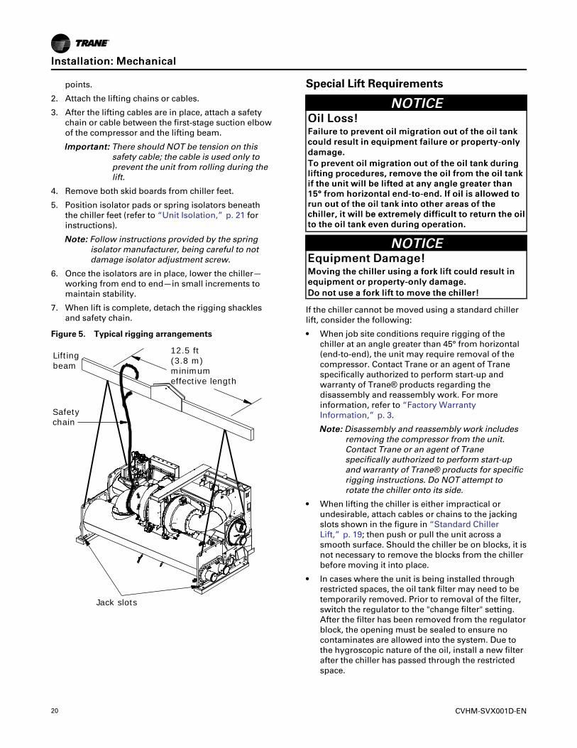
Standard Chiller Lift1. Insert rigging shackles at the points indicated in the
following figure. A 2 in. (50.8 mm)1.25 in. (31.8 mm)diameter lifting hole is provided at each of these
20 CVHM-SVX001D-EN
points.
2. Attach the lifting chains or cables.
3. After the lifting cables are in place, attach a safetychain or cable between the first-stage suction elbowof the compressor and the lifting beam.
IImmppoorrttaanntt:: There should NOT be tension on thissafety cable; the cable is used only toprevent the unit from rolling during thelift.
4. Remove both skid boards from chiller feet.
5. Position isolator pads or spring isolators beneaththe chiller feet (refer to “Unit Isolation,” p. 21 forinstructions).
NNoottee:: Follow instructions provided by the springisolator manufacturer, being careful to notdamage isolator adjustment screw.
6. Once the isolators are in place, lower the chiller—working from end to end—in small increments tomaintain stability.
7. When lift is complete, detach the rigging shacklesand safety chain.
Figure 5. Typical rigging arrangements
Jack slots
12.5 ft (3.8 m)minimum effective length
Safety chain
Lifting beam
Special Lift Requirements
NNOOTTIICCEEOOiill LLoossss!!FFaaiilluurree ttoo pprreevveenntt ooiill mmiiggrraattiioonn oouutt ooff tthhee ooiill ttaannkkccoouulldd rreessuulltt iinn eeqquuiippmmeenntt ffaaiilluurree oorr pprrooppeerrttyy--oonnllyyddaammaaggee..TToo pprreevveenntt ooiill mmiiggrraattiioonn oouutt ooff tthhee ooiill ttaannkk dduurriinngglliiffttiinngg pprroocceedduurreess,, rreemmoovvee tthhee ooiill ffrroomm tthhee ooiill ttaannkkiiff tthhee uunniitt wwiillll bbee lliifftteedd aatt aannyy aannggllee ggrreeaatteerr tthhaann1155°° ffrroomm hhoorriizzoonnttaall eenndd--ttoo--eenndd.. IIff ooiill iiss aalllloowweedd ttoorruunn oouutt ooff tthhee ooiill ttaannkk iinnttoo ootthheerr aarreeaass ooff tthheecchhiilllleerr,, iitt wwiillll bbee eexxttrreemmeellyy ddiiffffiiccuulltt ttoo rreettuurrnn tthhee ooiillttoo tthhee ooiill ttaannkk eevveenn dduurriinngg ooppeerraattiioonn..
NNOOTTIICCEEEEqquuiippmmeenntt DDaammaaggee!!MMoovviinngg tthhee cchhiilllleerr uussiinngg aa ffoorrkk lliifftt ccoouulldd rreessuulltt iinneeqquuiippmmeenntt oorr pprrooppeerrttyy--oonnllyy ddaammaaggee..DDoo nnoott uussee aa ffoorrkk lliifftt ttoo mmoovvee tthhee cchhiilllleerr!!
If the chiller cannot be moved using a standard chillerlift, consider the following:
• When job site conditions require rigging of thechiller at an angle greater than 45° from horizontal(end-to-end), the unit may require removal of thecompressor. Contact Trane or an agent of Tranespecifically authorized to perform start-up andwarranty of Trane® products regarding thedisassembly and reassembly work. For moreinformation, refer to “Factory WarrantyInformation,” p. 3.
NNoottee:: Disassembly and reassembly work includesremoving the compressor from the unit.Contact Trane or an agent of Tranespecifically authorized to perform start-upand warranty of Trane® products for specificrigging instructions. Do NOT attempt torotate the chiller onto its side.
• When lifting the chiller is either impractical orundesirable, attach cables or chains to the jackingslots shown in the figure in “Standard ChillerLift,” p. 19; then push or pull the unit across asmooth surface. Should the chiller be on blocks, it isnot necessary to remove the blocks from the chillerbefore moving it into place.
• In cases where the unit is being installed throughrestricted spaces, the oil tank filter may need to betemporarily removed. Prior to removal of the filter,switch the regulator to the "change filter" setting.After the filter has been removed from the regulatorblock, the opening must be sealed to ensure nocontaminates are allowed into the system. Due tothe hygroscopic nature of the oil, install a new filterafter the chiller has passed through the restrictedspace.
IInnssttaallllaattiioonn:: MMeecchhaanniiccaall
CVHM-SVX001D-EN 21
• If removal of the Adaptive Frequency™ drive (AFD)is necessary to move the chiller to the operatinglocation, refer to “Adaptive Frequency DriveRemoval and Installation,” p. 84. Also refer to“Factory Warranty Information,” p. 3.
Unit IsolationTo minimize sound and vibration transmission throughthe building structure and to ensure proper weightdistribution over the mounting surface, always installisolation pads or spring isolators under the chiller feet.
NNoottee:: Isolation pads (refer to the figure in “IsolationPads,” p. 21) are provided with each chillerunless spring isolators are specified on the salesorder.
Specific isolator loading data is provided in the unitsubmittal package. If necessary, contact your localTrane sales office for further information.
IImmppoorrttaanntt:: When determining placement of isolationpads or spring isolators, remember that thecontrol panel side of the unit is alwaysdesignated as the front side of the unit.
Isolation PadsWhen the unit is ready for final placement, positionisolation pads (18-in. [457.2-mm] sides) end for endunder the full length of the chiller leg. The padsmeasure 9 in. × 18 in. (228.6 mm x 457.2 mm) and onsome units there may be small gaps between pads.Pads are provided to cover entire foot. Place pad flushwith the outside edge of the chiller foot and leaveexcess material under the chiller.
Figure 6. Isolation pad and dimensions
A
B
C
A = 3/8 in. (9.5 mm)
B = 18 in. (457.2 mm)
C = 9 in. (228.6 mm)
Remember that the chiller must be level within 1/16 in.(1.6 mm) over its length and width after it is loweredonto the isolation pads. In addition, all pipingconnected to the chiller must be properly isolated andsupported so that it does not place any stress on theunit.
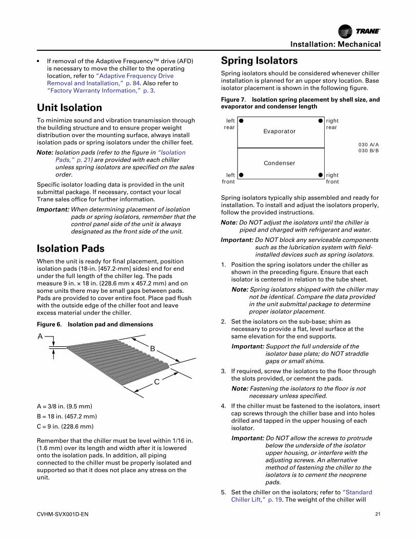
Spring IsolatorsSpring isolators should be considered whenever chillerinstallation is planned for an upper story location. Baseisolator placement is shown in the following figure.
Figure 7. Isolation spring placement by shell size, andevaporator and condenser length
Evaporator
Condenser
leftrear
leftfront
rightrear
rightfront
030 A/A030 B/B
Spring isolators typically ship assembled and ready forinstallation. To install and adjust the isolators properly,follow the provided instructions.
NNoottee:: Do NOT adjust the isolators until the chiller ispiped and charged with refrigerant and water.
IImmppoorrttaanntt:: Do NOT block any serviceable componentssuch as the lubrication system with field-installed devices such as spring isolators.
1. Position the spring isolators under the chiller asshown in the preceding figure. Ensure that eachisolator is centered in relation to the tube sheet.
NNoottee:: Spring isolators shipped with the chiller maynot be identical. Compare the data providedin the unit submittal package to determineproper isolator placement.
2. Set the isolators on the sub-base; shim asnecessary to provide a flat, level surface at thesame elevation for the end supports.
IImmppoorrttaanntt:: Support the full underside of theisolator base plate; do NOT straddlegaps or small shims.
3. If required, screw the isolators to the floor throughthe slots provided, or cement the pads.
NNoottee:: Fastening the isolators to the floor is notnecessary unless specified.
4. If the chiller must be fastened to the isolators, insertcap screws through the chiller base and into holesdrilled and tapped in the upper housing of eachisolator.
IImmppoorrttaanntt:: Do NOT allow the screws to protrudebelow the underside of the isolatorupper housing, or interfere with theadjusting screws. An alternativemethod of fastening the chiller to theisolators is to cement the neoprenepads.
5. Set the chiller on the isolators; refer to “StandardChiller Lift,” p. 19. The weight of the chiller will
IInnssttaallllaattiioonn:: MMeecchhaanniiccaall
22 CVHM-SVX001D-EN
force down the upper housing of each isolator, andcould cause it to rest on the isolator’s lowerhousing (refer to the following figure).
6. Check the clearance on each isolator. If thisdimension is less than 1/4 in. (6.35 mm) on anyisolator, use a wrench to turn the adjusting screwone complete revolution upward.
NNoottee:: When the load is applied to the isolators(refer to Step 5), the top plate of each isolatormoves down to compress the springs untileither the springs support the load or the topplate rests on the bottom housing of theisolator. If the springs are supporting the load,screwing down on the adjusting screw (referto Step 7) will raise the chiller.
7. Turn the adjusting screw on each of the remainingisolators to obtain the required minimum clearanceof 1/4 in. (6.35 mm).
8. Once the minimum required clearance is obtainedon each of the isolators, level the chiller by turningthe adjusting screw on each of the isolators on thelow side of the unit. Work from one isolator to thenext.
IImmppoorrttaanntt:: The chiller must be level to within 1/16 in. (1.6 mm) over its length andwidth, and the clearance of eachisolator must be at least 1/4 in.(6.35 mm).
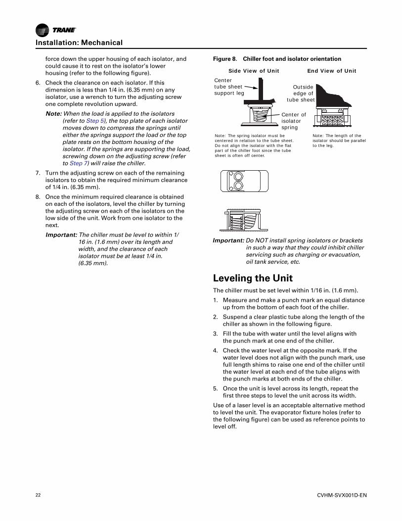
Figure 8. Chiller foot and isolator orientation
Side View of Unit End View of Unit
Center tube sheetsupport leg
Outside edge of
tube sheet
Center of isolator spring
Note: The spring isolator must be centered in relation to the tube sheet. Do not align the isolator with the flat part of the chiller foot since the tube sheet is often off center.
Note: The length of the isolator should be parallel to the leg.
IImmppoorrttaanntt:: Do NOT install spring isolators or bracketsin such a way that they could inhibit chillerservicing such as charging or evacuation,oil tank service, etc.
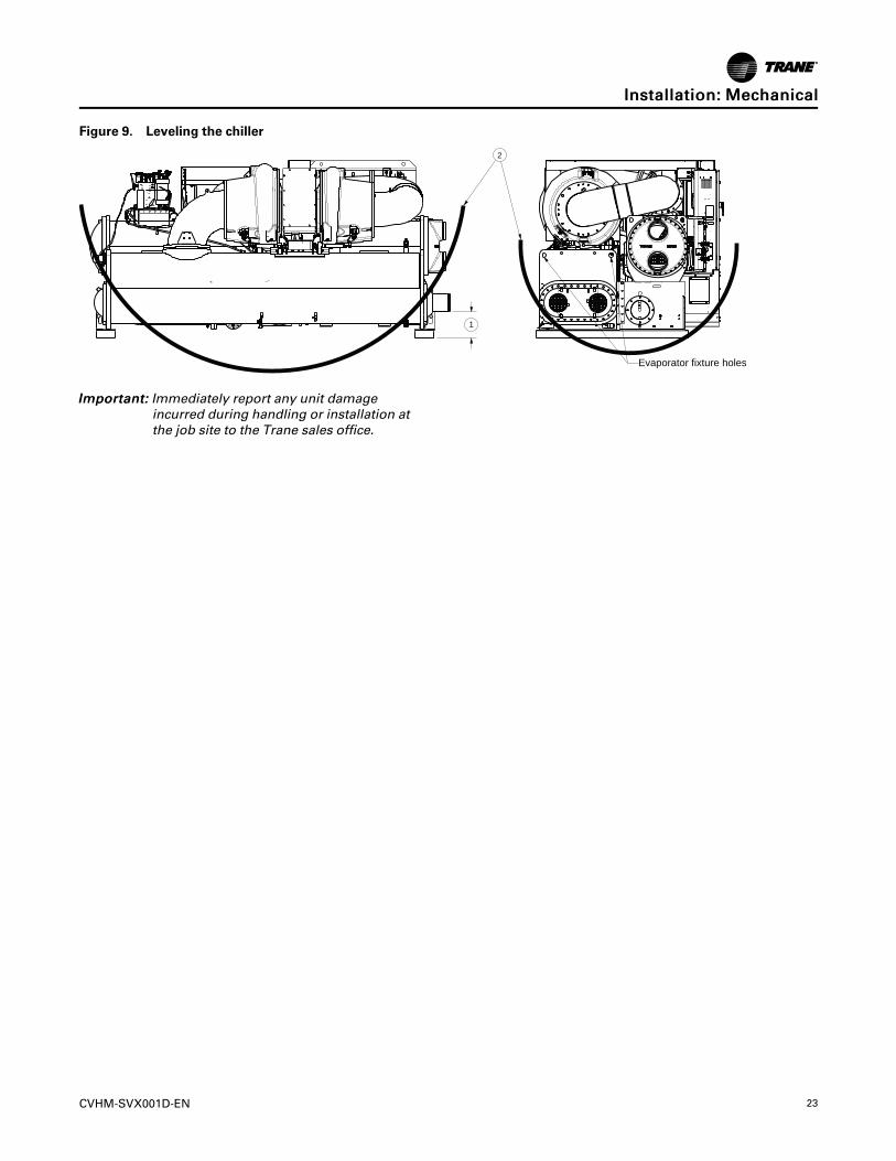
Leveling the UnitThe chiller must be set level within 1/16 in. (1.6 mm).
1. Measure and make a punch mark an equal distanceup from the bottom of each foot of the chiller.
2. Suspend a clear plastic tube along the length of thechiller as shown in the following figure.
3. Fill the tube with water until the level aligns withthe punch mark at one end of the chiller.
4. Check the water level at the opposite mark. If thewater level does not align with the punch mark, usefull length shims to raise one end of the chiller untilthe water level at each end of the tube aligns withthe punch marks at both ends of the chiller.
5. Once the unit is level across its length, repeat thefirst three steps to level the unit across its width.
Use of a laser level is an acceptable alternative methodto level the unit. The evaporator fixture holes (refer tothe following figure) can be used as reference points tolevel off.
IInnssttaallllaattiioonn:: MMeecchhaanniiccaall
CVHM-SVX001D-EN 23
Figure 9. Leveling the chiller
2
1
Evaporator fixture holes
IImmppoorrttaanntt:: Immediately report any unit damageincurred during handling or installation atthe job site to the Trane sales office.
IInnssttaallllaattiioonn:: MMeecchhaanniiccaall
24 CVHM-SVX001D-EN
Installation: Water PipingOverviewThe following water piping circuits must be installedand connected to the chiller:
• Pipe the evaporator into the chilled water circuit.
• Pipe the condenser into the cooling tower watercircuit.
NNoottee:: Piping must be arranged and supported to avoidstress on the equipment. It is stronglyrecommended that the piping contractor doesnot run pipe closer than 3 ft (0.9 m) minimum tothe equipment. This will allow for proper fit uponarrival of the unit at the job site. Any adjustmentthat is necessary can be made to the piping atthat time. Expenses that result from a failure tofollow this recommendation will NOT be paid byTrane.
Piping suggestions for each of the water circuits listedabove are outlined in “Evaporator and CondenserWater Piping,” p. 26. General recommendations for theinstallation of field-supplied piping components (e.g.,valves, flow switches, etc.) common to most chillerwater circuits are listed in the following sections.
Water TreatmentThe use of untreated or improperly treated water in aCenTraVac™ chiller may result in inefficient operationand possible tube damage.
IImmppoorrttaanntt:: Trane strongly recommends using theservices of a qualified water treatmentspecialist to determine necessary watertreatment. A label with a customerdisclaimer note is affixed to each unit.
NNOOTTIICCEEPPrrooppeerr WWaatteerr TTrreeaattmmeenntt RReeqquuiirreedd!!TThhee uussee ooff uunnttrreeaatteedd oorr iimmpprrooppeerrllyy ttrreeaatteedd wwaatteerrccoouulldd rreessuulltt iinn ssccaalliinngg,, eerroossiioonn,, ccoorrrroossiioonn,, aallggaaee oorrsslliimmee..UUssee tthhee sseerrvviicceess ooff aa qquuaalliiffiieedd wwaatteerr ttrreeaattmmeennttssppeecciiaalliisstt ttoo ddeetteerrmmiinnee wwhhaatt wwaatteerr ttrreeaattmmeenntt,, iiffaannyy,, iiss rreeqquuiirreedd.. TTrraannee aassssuummeess nnoo rreessppoonnssiibbiilliittyyffoorr eeqquuiippmmeenntt ffaaiilluurreess wwhhiicchh rreessuulltt ffrroomm uunnttrreeaatteeddoorr iimmpprrooppeerrllyy ttrreeaatteedd wwaatteerr,, oorr ssaalliinnee oorr bbrraacckkiisshhwwaatteerr..
Water Pressure GaugesLocate pressure gauge taps in a straight length of pipe.Place each tap a minimum of one pipe diameterdownstream of any elbow, orifice, etc. For example, fora 6 in. (16 cm) pipe, the tap would be at least 6 in. (16cm) from any elbow, orifice, etc.
Valves—Drains and VentsNNOOTTIICCEE
WWaatteerrbbooxx DDaammaaggee!!FFaaiilluurree ttoo ffoollllooww iinnssttrruuccttiioonnss ccoouulldd rreessuulltt iinnddaammaaggee ttoo tthhee wwaatteerrbbooxx..DDoo nnoott oovveerr--ttiigghhtteenn oorr uussee eexxcceessssiivvee TTeefflloonn®® ppiippeettaappee wwhheenn iinnssttaalllliinngg vvaallvveess,, ddrraaiinnss,, pplluuggss aannddvveennttss oonn wwaatteerrbbooxxeess..
1. Install field-supplied air vents and drain valves onthe waterboxes. Each waterbox is provided with aNational Pipe Thread Female (NPTF) vent and drainconnection; depending on the waterbox typesordered, the openings may be 1/4 in. (6.35 mm), 1/2 in. (12.7 mm), or 3/4 in. (19.05 mm).
NNOOTTIICCEEWWaatteerrbbooxx DDaammaaggee!!FFaaiilluurree ttoo ffoollllooww iinnssttrruuccttiioonnss ccoouulldd rreessuulltt iinnddaammaaggee ttoo tthhee wwaatteerrbbooxx dduuee ttoo hhyyddrroossttaattiicceexxppaannssiioonn..IInnssttaallll pprreessssuurree--rreelliieeff vvaallvveess iinn tthhee ccoonnddeennsseerraanndd eevvaappoorraattoorr wwaatteerr cciirrccuuiittss..
NNOOTTIICCEEEEqquuiippmmeenntt DDaammaaggee!!FFaaiilluurree ttoo ffoollllooww iinnssttrruuccttiioonnss ccoouulldd rreessuulltt iinneeqquuiippmmeenntt ddaammaaggee..DDoo NNOOTT aallllooww cchhiilllleerr ttoo ffrreeeezzee!! BBuunnddlleess mmuussttbbee ddrraaiinneedd aanndd aaiirr--bblloowwnn ddrryy iiff cchhiilllleerr iiss ssttoorreeddiinn aann uunnhheeaatteedd eeqquuiippmmeenntt rroooomm..
2. If necessary for the application, install pressure-relief valves at the drain connections on theevaporator and condenser waterboxes. To do so,add a tee with the relief valve attached to the drainvalve.
To determine whether or not pressure relief valvesare needed for a specific application, keep in mindthat:
a. Vessels with close-coupled shutoff valves maycause high potentially damaging hydrostaticpressures as fluid temperature rises.
b. Relief valves are required by American Societyof Mechanical Engineers (ASME) codes whenthe shell waterside is ASME. Follow ASMEguidelines or other applicable codes to ensureproper relief valve installation.
CVHM-SVX001D-EN 25
StrainersNNOOTTIICCEE
WWaatteerr BBoorrnn DDeebbrriiss!!TToo pprreevveenntt ccoommppoonneennttss ddaammaaggee,, ppiippee ssttrraaiinneerrssmmuusstt bbee iinnssttaalllleedd iinn tthhee wwaatteerr ssuupppplliieess ttoo pprrootteeccttccoommppoonneennttss ffrroomm wwaatteerr bboorrnn ddeebbrriiss.. TTrraannee iiss nnoottrreessppoonnssiibbllee ffoorr eeqquuiippmmeenntt--oonnllyy--ddaammaaggee ccaauusseeddbbyy wwaatteerr bboorrnn ddeebbrriiss..
Install a strainer in the entering side of each pipingcircuit to avoid possible tube plugging in the chillerwith debris.
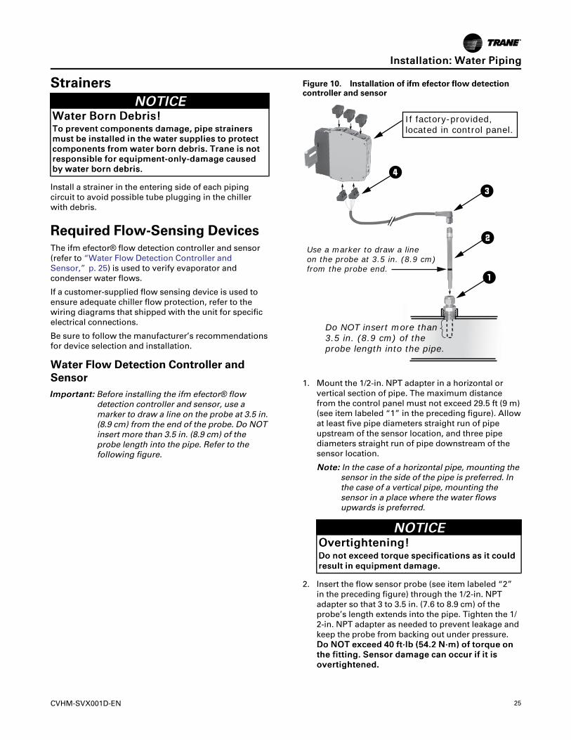
Required Flow-Sensing DevicesThe ifm efector® flow detection controller and sensor(refer to “Water Flow Detection Controller andSensor,” p. 25) is used to verify evaporator andcondenser water flows.
If a customer-supplied flow sensing device is used toensure adequate chiller flow protection, refer to thewiring diagrams that shipped with the unit for specificelectrical connections.
Be sure to follow the manufacturer’s recommendationsfor device selection and installation.
Water Flow Detection Controller andSensorIImmppoorrttaanntt:: Before installing the ifm efector® flow
detection controller and sensor, use amarker to draw a line on the probe at 3.5 in.(8.9 cm) from the end of the probe. Do NOTinsert more than 3.5 in. (8.9 cm) of theprobe length into the pipe. Refer to thefollowing figure.
Figure 10. Installation of ifm efector flow detectioncontroller and sensor
Components:A . E40174 – 1/2" NPT adapter (for �ow probe)B . SF6200 – Flow probeC . SN0150 – Flow control monitorD . E70231 – Combicon connectors (quantity 5)E . E10965 – Micro DC cable, 10m length, PUR jacketF. F53003 – Din rail, 40mm length
Output tocontrol cabinet
Jumper N
LAC
JumperFlow monitoringWire break monitoringTemperature monitoringPower-on delay timeSelection liquid / gas
Temperature monitoring canalso be incorporated usingterminals 10, 11, and 12.
To wire the �ow monitoringand wire-break monitoringrelay outputs in series, usethe wiring diagram at right.
Installation1. Install adapter (A) into pipe.
2. Mount �ow probe (B) into adapter (A).
3. Install DIN rail (F) into control cabinet.
4. Install control monitor (C) onto DIN rail (F).
5. Connect cable (E) to �ow probe (B), (hand tighten only).
6. Wire cable in combicon connectors (D) according towiring diagram.
7. Wire relay outputs for �ow, wire-break, and/ortemperature monitoring, according to wiring diagram.
If factory-provided, located in control panel.
Do NOT insert more than 3.5 in. (8.9 cm) of the probe length into the pipe.
43
2
1
Use a marker to draw a line on the probe at 3.5 in. (8.9 cm) from the probe end.
1. Mount the 1/2-in. NPT adapter in a horizontal orvertical section of pipe. The maximum distancefrom the control panel must not exceed 29.5 ft (9 m)(see item labeled “1” in the preceding figure). Allowat least five pipe diameters straight run of pipeupstream of the sensor location, and three pipediameters straight run of pipe downstream of thesensor location.
NNoottee:: In the case of a horizontal pipe, mounting thesensor in the side of the pipe is preferred. Inthe case of a vertical pipe, mounting thesensor in a place where the water flowsupwards is preferred.
NNOOTTIICCEEOOvveerrttiigghhtteenniinngg!!DDoo nnoott eexxcceeeedd ttoorrqquuee ssppeecciiffiiccaattiioonnss aass iitt ccoouullddrreessuulltt iinn eeqquuiippmmeenntt ddaammaaggee..
2. Insert the flow sensor probe (see item labeled “2”in the preceding figure) through the 1/2-in. NPTadapter so that 3 to 3.5 in. (7.6 to 8.9 cm) of theprobe’s length extends into the pipe. Tighten the 1/2-in. NPT adapter as needed to prevent leakage andkeep the probe from backing out under pressure.DDoo NNOOTT eexxcceeeedd 4400 fftt··llbb ((5544..22 NN··mm)) ooff ttoorrqquuee oonntthhee ffiittttiinngg.. SSeennssoorr ddaammaaggee ccaann ooccccuurr iiff iitt iissoovveerrttiigghhtteenneedd..
IInnssttaallllaattiioonn:: WWaatteerr PPiippiinngg
26 CVHM-SVX001D-EN
NNoottee:: When installed, the tip of the ifm efector®sensor probe must be at least 1 in. (2.54 cm)away from any pipe wall. Do NOT insert morethan 3.5 in. (8.9 cm) of the probe length intothe pipe.
3. Install the Micro DC Cable by inserting it throughthe wire openings on the back side of the controlpanel (see item labeled “3” in the preceding figure).Install the supplied Micro DC Cable (29.5 ft [9 m] inlength) to the Flow Probe and hand-tighten theconnector nut.
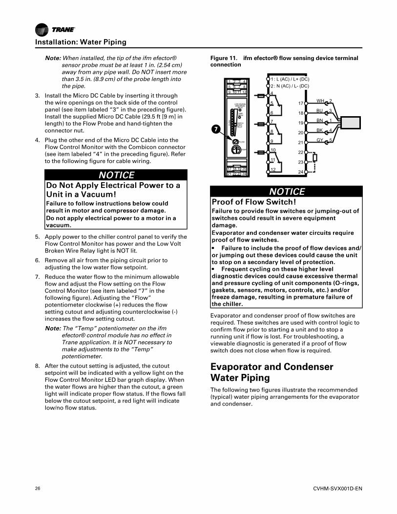
4. Plug the other end of the Micro DC Cable into theFlow Control Monitor with the Combicon connector(see item labeled “4” in the preceding figure). Referto the following figure for cable wiring.
NNOOTTIICCEEDDoo NNoott AAppppllyy EElleeccttrriiccaall PPoowweerr ttoo aaUUnniitt iinn aa VVaaccuuuumm!!FFaaiilluurree ttoo ffoollllooww iinnssttrruuccttiioonnss bbeellooww ccoouullddrreessuulltt iinn mmoottoorr aanndd ccoommpprreessssoorr ddaammaaggee..DDoo nnoott aappppllyy eelleeccttrriiccaall ppoowweerr ttoo aa mmoottoorr iinn aavvaaccuuuumm..
5. Apply power to the chiller control panel to verify theFlow Control Monitor has power and the Low VoltBroken Wire Relay light is NOT lit.
6. Remove all air from the piping circuit prior toadjusting the low water flow setpoint.
7. Reduce the water flow to the minimum allowableflow and adjust the Flow setting on the FlowControl Monitor (see item labeled “7” in thefollowing figure). Adjusting the “Flow”potentiometer clockwise (+) reduces the flowsetting cutout and adjusting counterclockwise (-)increases the flow setting cutout.
NNoottee:: The “Temp” potentiometer on the ifmefector® control module has no effect inTrane application. It is NOT necessary tomake adjustments to the “Temp”potentiometer.
8. After the cutout setting is adjusted, the cutoutsetpoint will be indicated with a yellow light on theFlow Control Monitor LED bar graph display. Whenthe water flows are higher than the cutout, a greenlight will indicate proper flow status. If the flows fallbelow the cutout setpoint, a red light will indicatelow/no flow status.
Figure 11. ifm efector®® flow sensing device terminalconnection
7
NNOOTTIICCEEPPrrooooff ooff FFllooww SSwwiittcchh!!FFaaiilluurree ttoo pprroovviiddee ffllooww sswwiittcchheess oorr jjuummppiinngg--oouutt ooffsswwiittcchheess ccoouulldd rreessuulltt iinn sseevveerree eeqquuiippmmeennttddaammaaggee..EEvvaappoorraattoorr aanndd ccoonnddeennsseerr wwaatteerr cciirrccuuiittss rreeqquuiirreepprrooooff ooff ffllooww sswwiittcchheess..•• FFaaiilluurree ttoo iinncclluuddee tthhee pprrooooff ooff ffllooww ddeevviicceess aanndd//oorr jjuummppiinngg oouutt tthheessee ddeevviicceess ccoouulldd ccaauussee tthhee uunniittttoo ssttoopp oonn aa sseeccoonnddaarryy lleevveell ooff pprrootteeccttiioonn..•• FFrreeqquueenntt ccyycclliinngg oonn tthheessee hhiigghheerr lleevveellddiiaaggnnoossttiicc ddeevviicceess ccoouulldd ccaauussee eexxcceessssiivvee tthheerrmmaallaanndd pprreessssuurree ccyycclliinngg ooff uunniitt ccoommppoonneennttss ((OO--rriinnggss,,ggaasskkeettss,, sseennssoorrss,, mmoottoorrss,, ccoonnttrroollss,, eettcc..)) aanndd//oorrffrreeeezzee ddaammaaggee,, rreessuullttiinngg iinn pprreemmaattuurree ffaaiilluurree oofftthhee cchhiilllleerr..
Evaporator and condenser proof of flow switches arerequired. These switches are used with control logic toconfirm flow prior to starting a unit and to stop arunning unit if flow is lost. For troubleshooting, aviewable diagnostic is generated if a proof of flowswitch does not close when flow is required.
Evaporator and CondenserWater PipingThe following two figures illustrate the recommended(typical) water piping arrangements for the evaporatorand condenser.
IInnssttaallllaattiioonn:: WWaatteerr PPiippiinngg
CVHM-SVX001D-EN 27
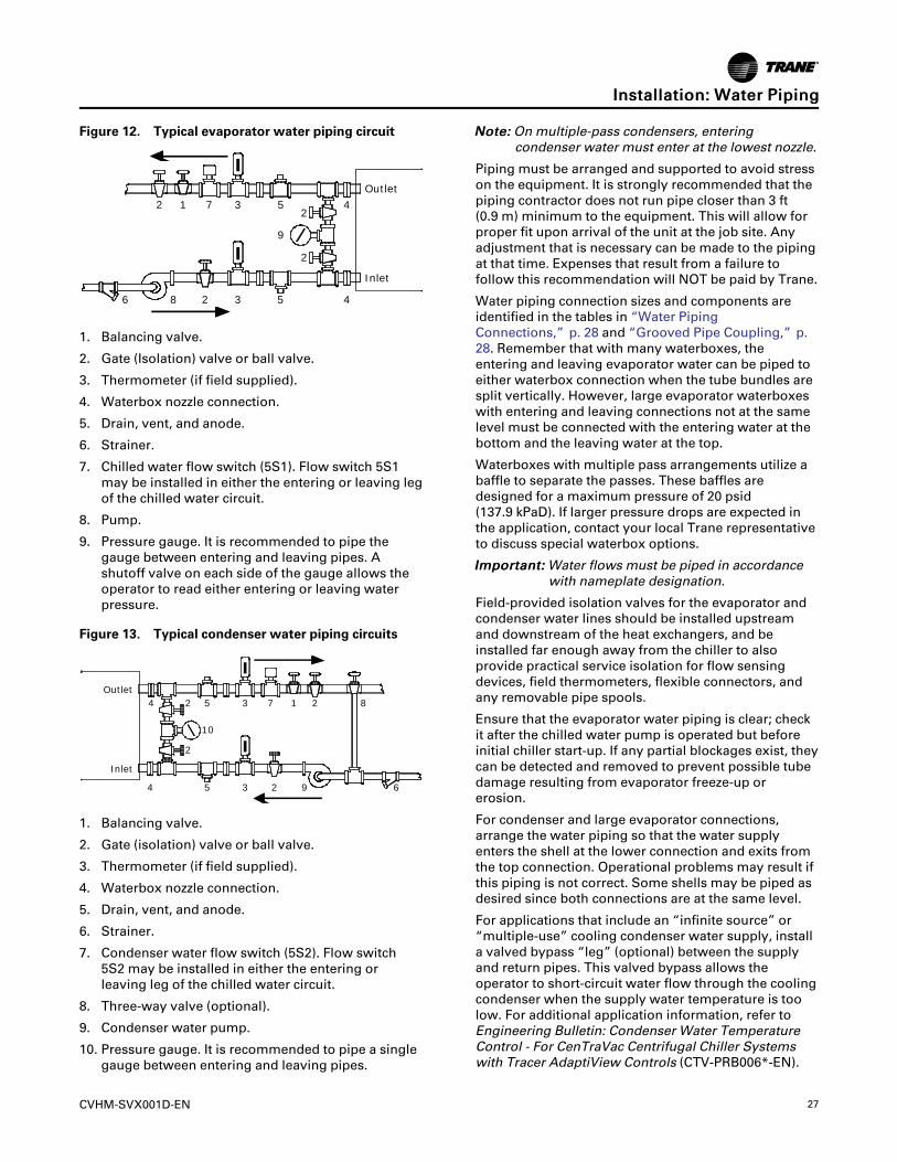
Figure 12. Typical evaporator water piping circuit
4
45
53
3
7
2
2 1
9
6
2
2
8
Outlet
Inlet
1. Balancing valve.
2. Gate (Isolation) valve or ball valve.
3. Thermometer (if field supplied).
4. Waterbox nozzle connection.
5. Drain, vent, and anode.
6. Strainer.
7. Chilled water flow switch (5S1). Flow switch 5S1may be installed in either the entering or leaving legof the chilled water circuit.
8. Pump.
9. Pressure gauge. It is recommended to pipe thegauge between entering and leaving pipes. Ashutoff valve on each side of the gauge allows theoperator to read either entering or leaving waterpressure.
Figure 13. Typical condenser water piping circuits
1 2
3
4 5
6
7 8
92
3
4 5
2
2
10
Outlet
Inlet
1. Balancing valve.
2. Gate (isolation) valve or ball valve.
3. Thermometer (if field supplied).
4. Waterbox nozzle connection.
5. Drain, vent, and anode.
6. Strainer.
7. Condenser water flow switch (5S2). Flow switch5S2 may be installed in either the entering orleaving leg of the chilled water circuit.
8. Three-way valve (optional).
9. Condenser water pump.
10. Pressure gauge. It is recommended to pipe a singlegauge between entering and leaving pipes.
NNoottee:: On multiple-pass condensers, enteringcondenser water must enter at the lowest nozzle.
Piping must be arranged and supported to avoid stresson the equipment. It is strongly recommended that thepiping contractor does not run pipe closer than 3 ft(0.9 m) minimum to the equipment. This will allow forproper fit upon arrival of the unit at the job site. Anyadjustment that is necessary can be made to the pipingat that time. Expenses that result from a failure tofollow this recommendation will NOT be paid by Trane.
Water piping connection sizes and components areidentified in the tables in “Water PipingConnections,” p. 28 and “Grooved Pipe Coupling,” p.28. Remember that with many waterboxes, theentering and leaving evaporator water can be piped toeither waterbox connection when the tube bundles aresplit vertically. However, large evaporator waterboxeswith entering and leaving connections not at the samelevel must be connected with the entering water at thebottom and the leaving water at the top.
Waterboxes with multiple pass arrangements utilize abaffle to separate the passes. These baffles aredesigned for a maximum pressure of 20 psid(137.9 kPaD). If larger pressure drops are expected inthe application, contact your local Trane representativeto discuss special waterbox options.
IImmppoorrttaanntt:: Water flows must be piped in accordancewith nameplate designation.
Field-provided isolation valves for the evaporator andcondenser water lines should be installed upstreamand downstream of the heat exchangers, and beinstalled far enough away from the chiller to alsoprovide practical service isolation for flow sensingdevices, field thermometers, flexible connectors, andany removable pipe spools.
Ensure that the evaporator water piping is clear; checkit after the chilled water pump is operated but beforeinitial chiller start-up. If any partial blockages exist, theycan be detected and removed to prevent possible tubedamage resulting from evaporator freeze-up orerosion.
For condenser and large evaporator connections,arrange the water piping so that the water supplyenters the shell at the lower connection and exits fromthe top connection. Operational problems may result ifthis piping is not correct. Some shells may be piped asdesired since both connections are at the same level.
For applications that include an “infinite source” or“multiple-use” cooling condenser water supply, installa valved bypass “leg” (optional) between the supplyand return pipes. This valved bypass allows theoperator to short-circuit water flow through the coolingcondenser when the supply water temperature is toolow. For additional application information, refer toEngineering Bulletin: Condenser Water TemperatureControl - For CenTraVac Centrifugal Chiller Systemswith Tracer AdaptiView Controls (CTV-PRB006*-EN).
IInnssttaallllaattiioonn:: WWaatteerr PPiippiinngg
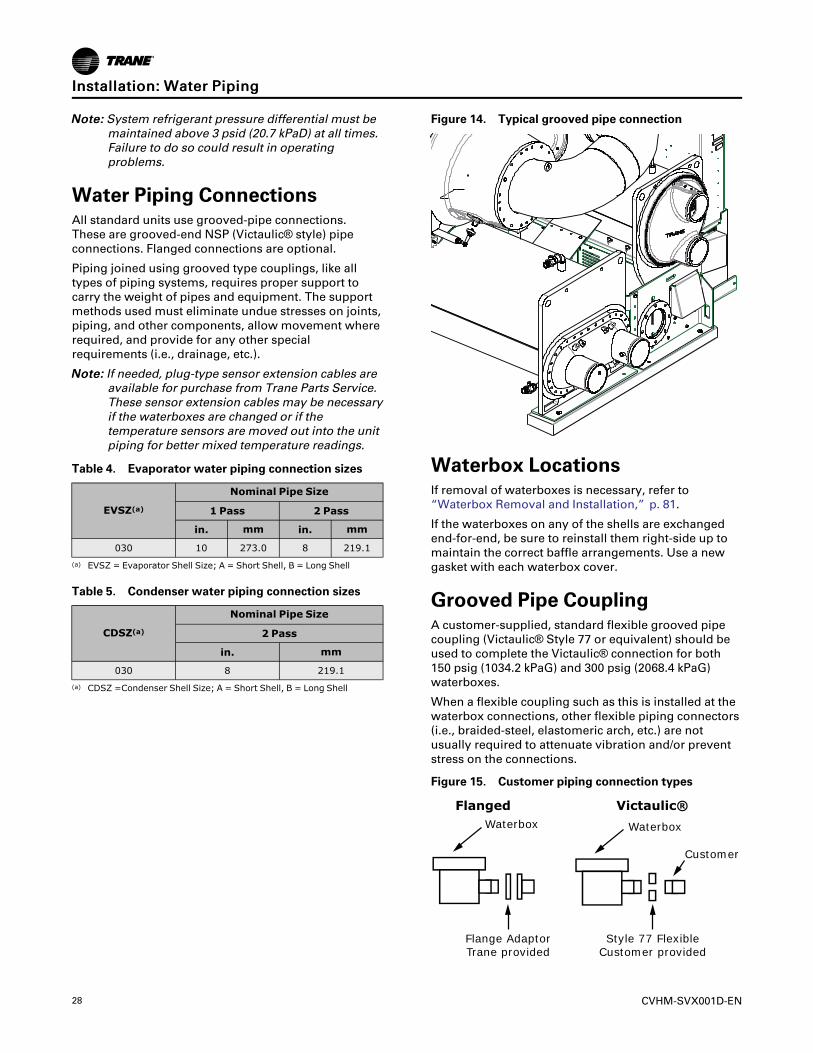
28 CVHM-SVX001D-EN
NNoottee:: System refrigerant pressure differential must bemaintained above 3 psid (20.7 kPaD) at all times.Failure to do so could result in operatingproblems.
Water Piping ConnectionsAll standard units use grooved-pipe connections.These are grooved-end NSP (Victaulic® style) pipeconnections. Flanged connections are optional.
Piping joined using grooved type couplings, like alltypes of piping systems, requires proper support tocarry the weight of pipes and equipment. The supportmethods used must eliminate undue stresses on joints,piping, and other components, allow movement whererequired, and provide for any other specialrequirements (i.e., drainage, etc.).
NNoottee:: If needed, plug-type sensor extension cables areavailable for purchase from Trane Parts Service.These sensor extension cables may be necessaryif the waterboxes are changed or if thetemperature sensors are moved out into the unitpiping for better mixed temperature readings.
Table 4. Evaporator water piping connection sizes
EVSZ(a)Nominal Pipe Size
1 Pass 2 Pass
in. mm in. mm
030 10 273.0 8 219.1(a) EVSZ = Evaporator Shell Size; A = Short Shell, B = Long Shell
Table 5. Condenser water piping connection sizes
CDSZ(a)Nominal Pipe Size
2 Pass
in. mm
030 8 219.1(a) CDSZ =Condenser Shell Size; A = Short Shell, B = Long Shell
Figure 14. Typical grooved pipe connection
Waterbox LocationsIf removal of waterboxes is necessary, refer to“Waterbox Removal and Installation,” p. 81.
If the waterboxes on any of the shells are exchangedend-for-end, be sure to reinstall them right-side up tomaintain the correct baffle arrangements. Use a newgasket with each waterbox cover.
Grooved Pipe CouplingA customer-supplied, standard flexible grooved pipecoupling (Victaulic® Style 77 or equivalent) should beused to complete the Victaulic® connection for both150 psig (1034.2 kPaG) and 300 psig (2068.4 kPaG)waterboxes.
When a flexible coupling such as this is installed at thewaterbox connections, other flexible piping connectors(i.e., braided-steel, elastomeric arch, etc.) are notusually required to attenuate vibration and/or preventstress on the connections.
Figure 15. Customer piping connection types
Flanged Victaulic®Waterbox Waterbox
Customer
Flange AdaptorTrane provided
Style 77 FlexibleCustomer provided
IInnssttaallllaattiioonn:: WWaatteerr PPiippiinngg
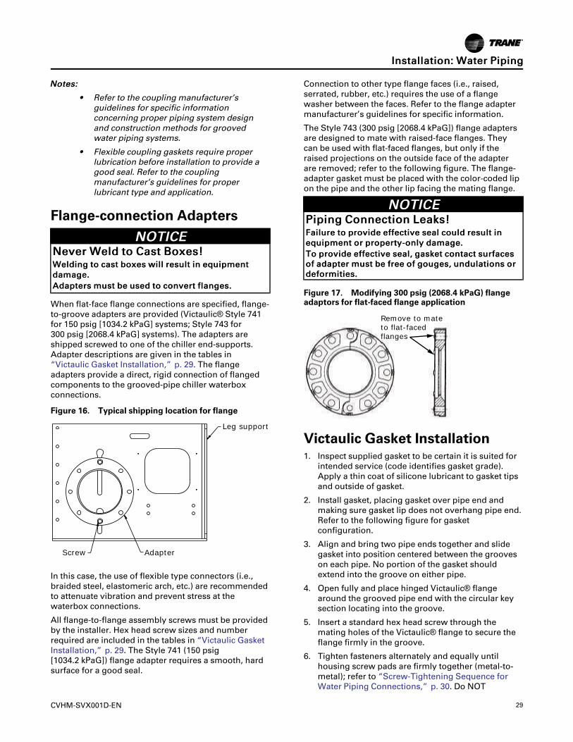
CVHM-SVX001D-EN 29
NNootteess::
• Refer to the coupling manufacturer’sguidelines for specific informationconcerning proper piping system designand construction methods for groovedwater piping systems.
• Flexible coupling gaskets require properlubrication before installation to provide agood seal. Refer to the couplingmanufacturer’s guidelines for properlubricant type and application.
Flange-connection AdaptersNNOOTTIICCEE
NNeevveerr WWeelldd ttoo CCaasstt BBooxxeess!!WWeellddiinngg ttoo ccaasstt bbooxxeess wwiillll rreessuulltt iinn eeqquuiippmmeennttddaammaaggee..AAddaapptteerrss mmuusstt bbee uusseedd ttoo ccoonnvveerrtt ffllaannggeess..
When flat-face flange connections are specified, flange-to-groove adapters are provided (Victaulic® Style 741for 150 psig [1034.2 kPaG] systems; Style 743 for300 psig [2068.4 kPaG] systems). The adapters areshipped screwed to one of the chiller end-supports.Adapter descriptions are given in the tables in“Victaulic Gasket Installation,” p. 29. The flangeadapters provide a direct, rigid connection of flangedcomponents to the grooved-pipe chiller waterboxconnections.
Figure 16. Typical shipping location for flange
Leg support
Screw Adapter
In this case, the use of flexible type connectors (i.e.,braided steel, elastomeric arch, etc.) are recommendedto attenuate vibration and prevent stress at thewaterbox connections.
All flange-to-flange assembly screws must be providedby the installer. Hex head screw sizes and numberrequired are included in the tables in “Victaulic GasketInstallation,” p. 29. The Style 741 (150 psig[1034.2 kPaG]) flange adapter requires a smooth, hardsurface for a good seal.
Connection to other type flange faces (i.e., raised,serrated, rubber, etc.) requires the use of a flangewasher between the faces. Refer to the flange adaptermanufacturer’s guidelines for specific information.
The Style 743 (300 psig [2068.4 kPaG]) flange adaptersare designed to mate with raised-face flanges. Theycan be used with flat-faced flanges, but only if theraised projections on the outside face of the adapterare removed; refer to the following figure. The flange-adapter gasket must be placed with the color-coded lipon the pipe and the other lip facing the mating flange.
NNOOTTIICCEEPPiippiinngg CCoonnnneeccttiioonn LLeeaakkss!!FFaaiilluurree ttoo pprroovviiddee eeffffeeccttiivvee sseeaall ccoouulldd rreessuulltt iinneeqquuiippmmeenntt oorr pprrooppeerrttyy--oonnllyy ddaammaaggee..TToo pprroovviiddee eeffffeeccttiivvee sseeaall,, ggaasskkeett ccoonnttaacctt ssuurrffaacceessooff aaddaapptteerr mmuusstt bbee ffrreeee ooff ggoouuggeess,, uunndduullaattiioonnss oorrddeeffoorrmmiittiieess..
Figure 17. Modifying 300 psig (2068.4 kPaG) flangeadaptors for flat-faced flange application
Remove to mateto flat-faced flanges
Victaulic Gasket Installation1. Inspect supplied gasket to be certain it is suited for
intended service (code identifies gasket grade).Apply a thin coat of silicone lubricant to gasket tipsand outside of gasket.
2. Install gasket, placing gasket over pipe end andmaking sure gasket lip does not overhang pipe end.Refer to the following figure for gasketconfiguration.
3. Align and bring two pipe ends together and slidegasket into position centered between the grooveson each pipe. No portion of the gasket shouldextend into the groove on either pipe.
4. Open fully and place hinged Victaulic® flangearound the grooved pipe end with the circular keysection locating into the groove.
5. Insert a standard hex head screw through themating holes of the Victaulic® flange to secure theflange firmly in the groove.
6. Tighten fasteners alternately and equally untilhousing screw pads are firmly together (metal-to-metal); refer to “Screw-Tightening Sequence forWater Piping Connections,” p. 30. Do NOT
IInnssttaallllaattiioonn:: WWaatteerr PPiippiinngg
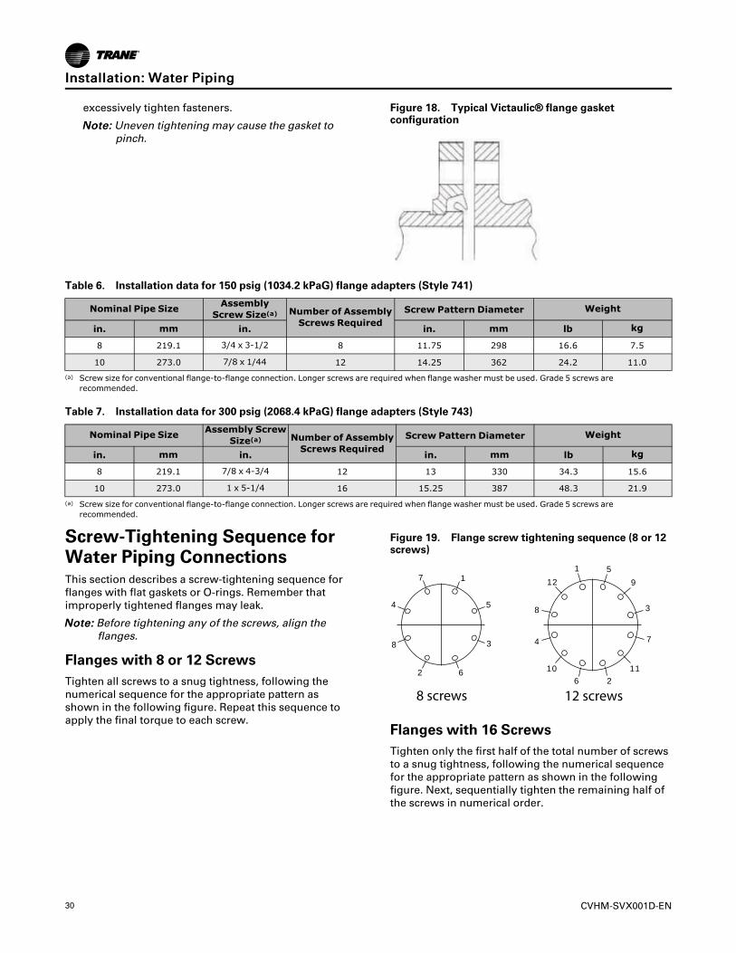
30 CVHM-SVX001D-EN
excessively tighten fasteners.
NNoottee:: Uneven tightening may cause the gasket topinch.
Figure 18. Typical Victaulic®® flange gasketconfiguration
Table 6. Installation data for 150 psig (1034.2 kPaG) flange adapters (Style 741)
Nominal Pipe Size AssemblyScrew Size(a) Number of Assembly
Screws RequiredScrew Pattern Diameter Weight
in. mm in. in. mm lb kg
8 219.1 3/4 x 3-1/2 8 11.75 298 16.6 7.5
10 273.0 7/8 x 1/44 12 14.25 362 24.2 11.0(a) Screw size for conventional flange-to-flange connection. Longer screws are required when flange washer must be used. Grade 5 screws are
recommended.
Table 7. Installation data for 300 psig (2068.4 kPaG) flange adapters (Style 743)
Nominal Pipe Size Assembly ScrewSize(a) Number of Assembly
Screws RequiredScrew Pattern Diameter Weight
in. mm in. in. mm lb kg
8 219.1 7/8 x 4-3/4 12 13 330 34.3 15.6
10 273.0 1 x 5-1/4 16 15.25 387 48.3 21.9(a) Screw size for conventional flange-to-flange connection. Longer screws are required when flange washer must be used. Grade 5 screws are
recommended.
Screw-Tightening Sequence forWater Piping ConnectionsThis section describes a screw-tightening sequence forflanges with flat gaskets or O-rings. Remember thatimproperly tightened flanges may leak.
NNoottee:: Before tightening any of the screws, align theflanges.
Flanges with 8 or 12 ScrewsTighten all screws to a snug tightness, following thenumerical sequence for the appropriate pattern asshown in the following figure. Repeat this sequence toapply the final torque to each screw.
Figure 19. Flange screw tightening sequence (8 or 12screws)
1
3
4 5
7
8
2 6
8 screws
1
3
4
10 11
9
5
7
8
12
26
12 screws
Flanges with 16 ScrewsTighten only the first half of the total number of screwsto a snug tightness, following the numerical sequencefor the appropriate pattern as shown in the followingfigure. Next, sequentially tighten the remaining half ofthe screws in numerical order.
IInnssttaallllaattiioonn:: WWaatteerr PPiippiinngg
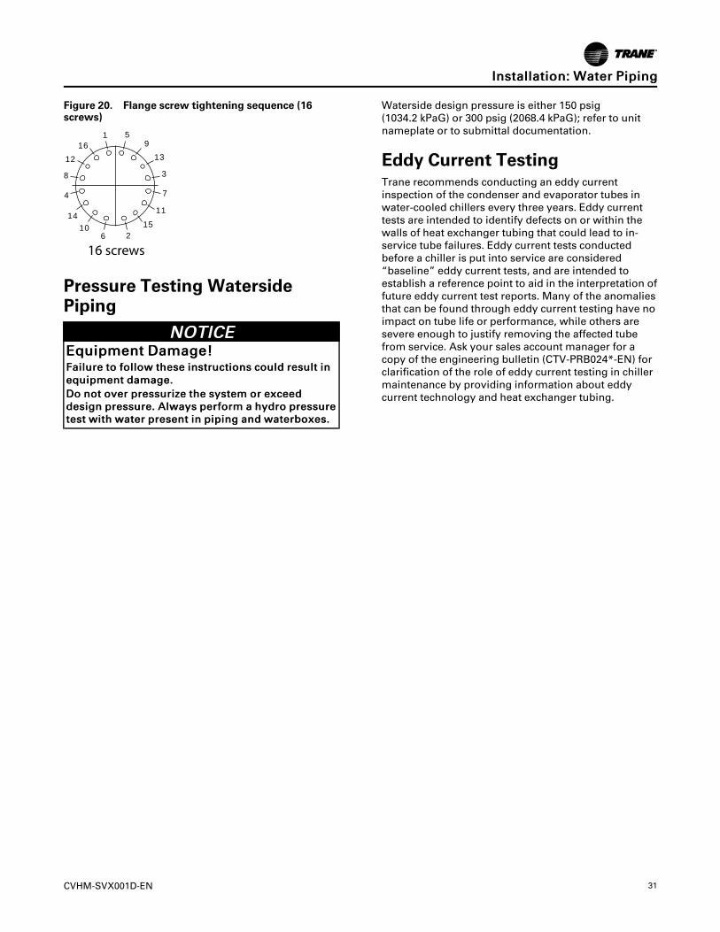
CVHM-SVX001D-EN 31
Figure 20. Flange screw tightening sequence (16screws)
16 screws
1 59
2
3
4
6
7
8
10
16
1514
1312
11
Pressure Testing WatersidePiping
NNOOTTIICCEEEEqquuiippmmeenntt DDaammaaggee!!FFaaiilluurree ttoo ffoollllooww tthheessee iinnssttrruuccttiioonnss ccoouulldd rreessuulltt iinneeqquuiippmmeenntt ddaammaaggee..DDoo nnoott oovveerr pprreessssuurriizzee tthhee ssyysstteemm oorr eexxcceeeeddddeessiiggnn pprreessssuurree.. AAllwwaayyss ppeerrffoorrmm aa hhyyddrroo pprreessssuurreetteesstt wwiitthh wwaatteerr pprreesseenntt iinn ppiippiinngg aanndd wwaatteerrbbooxxeess..
Waterside design pressure is either 150 psig(1034.2 kPaG) or 300 psig (2068.4 kPaG); refer to unitnameplate or to submittal documentation.
Eddy Current TestingTrane recommends conducting an eddy currentinspection of the condenser and evaporator tubes inwater-cooled chillers every three years. Eddy currenttests are intended to identify defects on or within thewalls of heat exchanger tubing that could lead to in-service tube failures. Eddy current tests conductedbefore a chiller is put into service are considered“baseline” eddy current tests, and are intended toestablish a reference point to aid in the interpretation offuture eddy current test reports. Many of the anomaliesthat can be found through eddy current testing have noimpact on tube life or performance, while others aresevere enough to justify removing the affected tubefrom service. Ask your sales account manager for acopy of the engineering bulletin (CTV-PRB024*-EN) forclarification of the role of eddy current testing in chillermaintenance by providing information about eddycurrent technology and heat exchanger tubing.
IInnssttaallllaattiioonn:: WWaatteerr PPiippiinngg
32 CVHM-SVX001D-EN
Vent PipingRefrigerant Vent LineGeneral RequirementsState and local codes, and ASHRAE Standard 15contain requirements for venting the relief device onthe chiller to the atmosphere outside of the building.These requirements include, but are not limited to,permitted materials, sizing, and proper termination.
NNoottee:: The following information is a general outline ofvent-line installation requirements based onASHRAE Standard 15. Most codes containsimilar requirements but may vary in somesignificant areas. The installer must check stateand local codes and follow the specificrequirements applicable to the location.
Purge DischargeTo comply with ASHRAE Standard 15, the dischargepiping from purge units that remove non-condensablegas from refrigerating systems must conform to theASHRAE Standard 15 requirements for relief piping. Tohelp meet this requirement, the purge discharge isfactory-piped to the relief device assembly.
Vent Line MaterialsAll materials in the relief device vent system must becompatible with the refrigerant in use. Commonly usedand accepted piping materials include steel and drain/waste/vent (DWV) copper. Consult local codes forrestrictions on materials. Consult with themanufacturers of any field-provided components ormaterials for acceptable material compatibility.
NNoottee:: PVC piping is compatible with the refrigerant butthe glue that joins the sections of plastic pipemay not be. When considering a vent systemconstructed of plastic piping such as PVC, ensurethat both the pipe material and the adhesivehave been tested for refrigerant compatibility. Inaddition, verify that the local codes permit PVCfor refrigerant vent lines; even though ASHRAEStandard 15 doesn’t prohibit its use, some localcodes do.
Testing conducted in Trane laboratories has qualifiedthe following materials for PVC pipe construction asbeing compatible with the refrigerant:
Primer/Cleaner:
• Hercules—PVC Primer #60-465
• RECTORSEAL® PVC Cleaner—Sam™ CL-3L
Adhesives:
• Hercules—Clear PVC, Medium Body/Medium Set,#60-020
• RECTORSEAL®—PVC Cement, Gene™ 404L
Flexible connection devices for vibration isolation mustalso be compatible with the vented refrigerant. Aflexible stainless-steel pump connector (such as thestainless-steel type MFP, style HNE, flexible pumpconnector from Vibration Mounting and Control, Inc.)or equivalent is recommended.
Vent Line SizingVent line size must conform to local codes andrequirements. In most cases, local codes are based onASHRAE Standard 15. ASHRAE Standard 15 providesspecific requirements for the discharge piping thatallows pressure-relief devices to safely vent refrigerantto the atmosphere if over-pressurization occurs. In part,the standard mandates that:
• The minimum pipe size of the vent line must equalthe size of the discharge connection on thepressure-relief device. A larger vent line size maybe necessary, depending on the length of the run.
• Two or more relief devices can be piped togetheronly if the vent line is sized to handle all devicesthat could relieve at the same time.
• When two or more relief devices share a commonvent line, the shared line must equal or exceed thesum of the outlet areas of all upstream reliefdevices, depending on the resulting back pressure.
ASHRAE Standard 15 provides guidance fordetermining the maximum vent line length. It alsoprovides the equation and data necessary to properlysize the vent line at the outlet of a pressure-relief deviceor fusible plug (for more information, refer to “VentLine Sizing Reference,” p. 36).
The equation accounts for the relationship betweenpipe diameter, equivalent pipe length, and the pressuredifference between the vent line inlet and outlet to helpensure that the vent line system provides sufficientflow capacity.
The table in “Vent Line Sizing Reference,” p. 36provides additional information based on ASHRAEStandard 15, including:
• Capacities of various vent line sizes and lengths.However, this data applies only to conventionalpressure-relief valves and NOT to balanced reliefvalves, rupture members (as used on Trane®centrifugal chillers), fusible plugs, or pilot-operatedvalves.
• A simplified method to determine the appropriatevent-line size, using the figure in “Vent Line SizingReference,” p. 36. Enter the figure with the total CCvalue, read across to a pipe curve and down to findthe maximum allowable length for that size pipe.
CVHM-SVX001D-EN 33
NNoottee:: To determine the total CC value for a specificunit, add the appropriate CC values for theevaporator, standard condenser, andeconomizer. If the unit is equipped with anyoptions (e.g., heat recovery, free cooling, oran auxiliary condenser), add the applicable CCvalue(s) for those options to the total as well.
NNoottee:: The table and figure in “Vent Line SizingReference,” p. 36 are applicable only for non-manifolded vent-line runs connected to a 15 psig(103.4 kPaG) rupture disk relief device. The pipelength provided by the table is in “equivalentfeet.” The vent-line length in equivalent feet isthe sum of the linear pipe length plus theequivalent length of the fittings (e.g., elbows).
Vent Line InstallationIImmppoorrttaanntt:: Before constructing the rupture disk vent
line, consult local codes for applicableguidelines and constraints.
All CenTraVac™ centrifugal chillers are equipped withrupture disks. If refrigerant pressure within theevaporator exceeds 15 psig (103.4 kPaG), the rupturedisk breaks and shell pressure is relieved as refrigerantescapes from the chiller.
A cross-section of the rupture disk assembly appearsinthe following figure (rupture disk location and crosssection), along with an illustration indicating thelocation of the rupture disk on the suction elbow.
IImmppoorrttaanntt:: If a RuptureGuard™ is to be installed,remove and discard the factory-installedrupture disk; for more information, refer toInstallation, Operation, and Maintenance:RuptureGuard Pressure Relief SystemOption (CTV-SVX06*-EN).
Several general recommendations for rupture disk ventline installation are outlined as follows.
NNoottee:: If the rupture disk was removed for service orvent-line piping installation, the rupture diskmust be reinstalled (as shown in the followingfigure [rupture disk location and cross section]).Refer to the following procedure and contactCenTraVac™ Chiller Technical Service whenreinstalling the rupture disk.
• Verify that the vacuum support side of the rupturedisk is positioned as shown in the cross-sectionview that appears in the following figure (rupturedisk location and cross section).
– Install the two bottom hex head screws thoughthe pipe flanges.
– Install the rupture disk with a gasket on eachside between the pipe flanges. Orient the diskwith the reference arrow or vacuum support barfacing the chiller side as shown in the followingfigure (rupture disk location and cross section).
– Install the two top hex head screws.
– Center the disk and gaskets to the flange bore.
– Hand-tighten all screws, assuring equalpressure.
– Use a torque wrench set to 240 in·lb (27.1 N·m)with a 9/16-in. socket.
– Tighten screws in a star pattern, one half turneach, to maintain even pressure on the disk.
– Final torque on all screws should be 240 in·lb(27.1 N·m).
• When attaching the vent line to the chiller, do NOTapply threading torque to the outside pipe of therupture disk assembly.
NNOOTTIICCEERRuuppttuurree DDiisskk DDaammaaggee!!FFaaiilluurree ttoo ffoollllooww iinnssttrruuccttiioonn ccoouulldd rreessuulltt iinnddaammaaggee ttoo tthhee rruuppttuurree ddiisskk aasssseemmbbllyy..DDoo nnoott aappppllyy tthhrreeaaddiinngg ttoorrqquuee ttoo tthhee oouuttssiiddee ppiippee..
• Provide support as needed for the vent line. DoNOT use the rupture disk assembly to support thevent-line piping.
• Use a flexible connection between the vent line andthe rupture disk assembly to avoid placing stress onthe rupture disk. (Stress can alter rupture pressureand cause the disk to break prematurely.) Theflexible connector used to isolate the rupture diskfrom excessive vent line vibration must becompatible with the refrigerant in use. Use aflexible, steel connector (such as the stainless-steeltype MFP, style HNE, flexible pump connector fromVibration Mounting and Control, Inc.), orequivalent. Refer to the following figure(arrangement for rupture disk relief piping) for arecommended relief piping arrangement.
• An individual vent line is normally installed for eachrelief device. It is permissible to manifold therupture disks of several machines into a commonvent line provided that the appropriate ASHRAEStandards and local code requirements formanifolded relief devices are followed.
NNoottee:: The following figure (arrangement forrupture disk relief piping) does NOT apply formanifolded vent lines.
WWAARRNNIINNGGPPrreessssuurree--RReelliieeff DDeevviiccee DDiisscchhaarrggeeHHaazzaarrdd!!AAnn iimmpprrooppeerr vveenntt--lliinnee tteerrmmiinnaattiioonn ccoouulldd rreessuulltt iinnddeeaatthh oorr sseerriioouuss iinnjjuurryy oorr eeqquuiippmmeenntt ddaammaaggee..WWhheenn aa pprreessssuurree--rreelliieeff ddeevviiccee ooppeerraatteess,, iitt ccoouullddddiisscchhaarrggee aa llaarrggee aammoouunntt ooff fflluuiidd aanndd//oorr vvaappoorr..UUnniittss MMUUSSTT bbee eeqquuiippppeedd wwiitthh aa vveenntt--lliinneetteerrmmiinnaattiioonn tthhaatt ddiisscchhaarrggeess oouuttddoooorrss iinn aann aarreeaatthhaatt wwiillll nnoott sspprraayy rreeffrriiggeerraanntt oonn aannyyoonnee..
VVeenntt PPiippiinngg
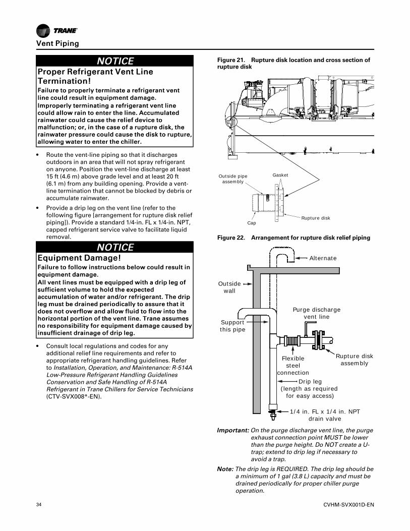
34 CVHM-SVX001D-EN
NNOOTTIICCEEPPrrooppeerr RReeffrriiggeerraanntt VVeenntt LLiinneeTTeerrmmiinnaattiioonn!!FFaaiilluurree ttoo pprrooppeerrllyy tteerrmmiinnaattee aa rreeffrriiggeerraanntt vveennttlliinnee ccoouulldd rreessuulltt iinn eeqquuiippmmeenntt ddaammaaggee..IImmpprrooppeerrllyy tteerrmmiinnaattiinngg aa rreeffrriiggeerraanntt vveenntt lliinneeccoouulldd aallllooww rraaiinn ttoo eenntteerr tthhee lliinnee.. AAccccuummuullaatteeddrraaiinnwwaatteerr ccoouulldd ccaauussee tthhee rreelliieeff ddeevviiccee ttoommaallffuunnccttiioonn;; oorr,, iinn tthhee ccaassee ooff aa rruuppttuurree ddiisskk,, tthheerraaiinnwwaatteerr pprreessssuurree ccoouulldd ccaauussee tthhee ddiisskk ttoo rruuppttuurree,,aalllloowwiinngg wwaatteerr ttoo eenntteerr tthhee cchhiilllleerr..
• Route the vent-line piping so that it dischargesoutdoors in an area that will not spray refrigeranton anyone. Position the vent-line discharge at least15 ft (4.6 m) above grade level and at least 20 ft(6.1 m) from any building opening. Provide a vent-line termination that cannot be blocked by debris oraccumulate rainwater.
• Provide a drip leg on the vent line (refer to thefollowing figure [arrangement for rupture disk reliefpiping]). Provide a standard 1/4-in. FL x 1/4-in. NPT,capped refrigerant service valve to facilitate liquidremoval.
NNOOTTIICCEEEEqquuiippmmeenntt DDaammaaggee!!FFaaiilluurree ttoo ffoollllooww iinnssttrruuccttiioonnss bbeellooww ccoouulldd rreessuulltt iinneeqquuiippmmeenntt ddaammaaggee..AAllll vveenntt lliinneess mmuusstt bbee eeqquuiippppeedd wwiitthh aa ddrriipp lleegg ooffssuuffffiicciieenntt vvoolluummee ttoo hhoolldd tthhee eexxppeecctteeddaaccccuummuullaattiioonn ooff wwaatteerr aanndd//oorr rreeffrriiggeerraanntt.. TThhee ddrriipplleegg mmuusstt bbee ddrraaiinneedd ppeerriiooddiiccaallllyy ttoo aassssuurree tthhaatt iittddooeess nnoott oovveerrffllooww aanndd aallllooww fflluuiidd ttoo ffllooww iinnttoo tthheehhoorriizzoonnttaall ppoorrttiioonn ooff tthhee vveenntt lliinnee.. TTrraannee aassssuummeessnnoo rreessppoonnssiibbiilliittyy ffoorr eeqquuiippmmeenntt ddaammaaggee ccaauusseedd bbyyiinnssuuffffiicciieenntt ddrraaiinnaaggee ooff ddrriipp lleegg..
• Consult local regulations and codes for anyadditional relief line requirements and refer toappropriate refrigerant handling guidelines. Referto Installation, Operation, and Maintenance: R-514ALow-Pressure Refrigerant Handling GuidelinesConservation and Safe Handling of R-514ARefrigerant in Trane Chillers for Service Technicians(CTV-SVX008*-EN).
Figure 21. Rupture disk location and cross section ofrupture disk
Outside pipeassembly
Gasket
CapRupture disk
Figure 22. Arrangement for rupture disk relief piping
Alternate
Outsidewall
Supportthis pipe
Purge dischargevent line
Rupture diskassembly
Flexiblesteel
connection
1/4 in. FL x 1/4 in. NPTdrain valve
Drip leg(length as required
for easy access)
IImmppoorrttaanntt:: On the purge discharge vent line, the purgeexhaust connection point MUST be lowerthan the purge height. Do NOT create a U-trap; extend to drip leg if necessary toavoid a trap.
NNoottee:: The drip leg is REQUIRED. The drip leg should bea minimum of 1 gal (3.8 L) capacity and must bedrained periodically for proper chiller purgeoperation.
VVeenntt PPiippiinngg
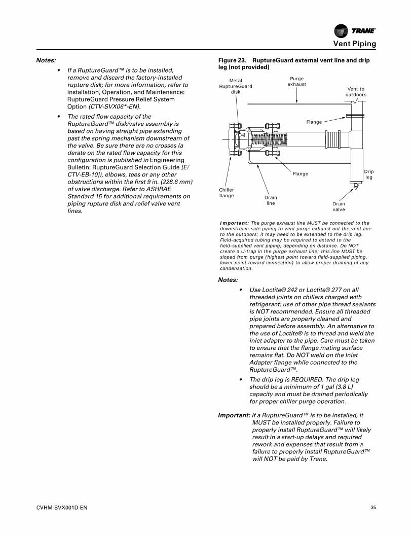
CVHM-SVX001D-EN 35
NNootteess::
• If a RuptureGuard™ is to be installed,remove and discard the factory-installedrupture disk; for more information, refer toInstallation, Operation, and Maintenance:RuptureGuard Pressure Relief SystemOption (CTV-SVX06*-EN).
• The rated flow capacity of theRuptureGuard™ disk/valve assembly isbased on having straight pipe extendingpast the spring mechanism downstream ofthe valve. Be sure there are no crosses (aderate on the rated flow capacity for thisconfiguration is published in EngineeringBulletin: RuptureGuard Selection Guide [E/CTV-EB-10]), elbows, tees or any otherobstructions within the first 9 in. (228.6 mm)of valve discharge. Refer to ASHRAEStandard 15 for additional requirements onpiping rupture disk and relief valve ventlines.
Figure 23. RuptureGuard external vent line and dripleg (not provided)
MetalRuptureGuard
disk
Purgeexhaust
Flange
Vent tooutdoors
Flange
Drainline
Chillerflange
Drainvalve
Dripleg
Important: The purge exhaust line MUST be connected to the downstream side piping to vent purge exhaust out the vent line to the outdoors; it may need to be extended to the drip leg. Field-acquired tubing may be required to extend to the field-supplied vent piping, depending on distance. Do NOT create a U-trap in the purge exhaust line; this line MUST be sloped from purge (highest point toward field-supplied piping, lower point toward connection) to allow proper draining of any condensation.
NNootteess::
• Use Loctite® 242 or Loctite® 277 on allthreaded joints on chillers charged withrefrigerant; use of other pipe thread sealantsis NOT recommended. Ensure all threadedpipe joints are properly cleaned andprepared before assembly. An alternative tothe use of Loctite® is to thread and weld theinlet adapter to the pipe. Care must be takento ensure that the flange mating surfaceremains flat. Do NOT weld on the InletAdapter flange while connected to theRuptureGuard™.
• The drip leg is REQUIRED. The drip legshould be a minimum of 1 gal (3.8 L)capacity and must be drained periodicallyfor proper chiller purge operation.
IImmppoorrttaanntt:: If a RuptureGuard™ is to be installed, itMUST be installed properly. Failure toproperly install RuptureGuard™ will likelyresult in a start-up delays and requiredrework and expenses that result from afailure to properly install RuptureGuard™will NOT be paid by Trane.
VVeenntt PPiippiinngg
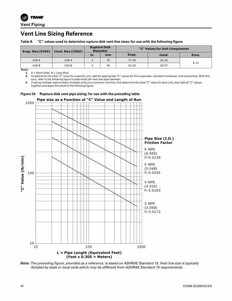
36 CVHM-SVX001D-EN
Vent Line Sizing ReferenceTable 8. “C” values used to determine rupture disk vent line sizes; for use with the following figure
Evap. Size (EVSZ) Cond. Size (CDSZ)Rupture DiskDiameter
“C” Values for Unit Components
in. mm Evap. Cond. Econ.
030 A 030 A 3 76 37.50 26.255.12
030 B 030 B 3 76 42.25 29.57Notes:
1. A = Short Shell; B = Long Shell2. To determine the total “C” value for a specific unit, add the appropriate “C” values for the evaporator, standard condenser, and economizer. With this
sum, refer to the following figure to determine the vent-line pipe diameter.3. If piping multiple rupture disks (multiple units) to a common vent line, first determine the total “C” value for each unit, then add all “C” values
together and apply the result to the following figure.
Figure 24. Rupture disk vent pipe sizing; for use with the preceding table
Pipe size as a Function of “C” Value and Length of Run1000
100
1010 100 1000
6 NPS(6.065)f=0.0149
5 NPS(5.048)f=0.0155
4 NPS(4.026)f=0.0163
3 NPS(3.068)f=0.0173
Pipe Size (I.D.)Friction Factor
“C”
Valu
e (
lb/
min
)
L = Pipe Length (Equivalent Feet)(Feet x 0.305 = Meters)
NNoottee:: The preceding figure, provided as a reference, is based on ASHRAE Standard 15. Vent line size is typicallydictated by state or local code which may be different from ASHRAE Standard 15 requirements.
VVeenntt PPiippiinngg
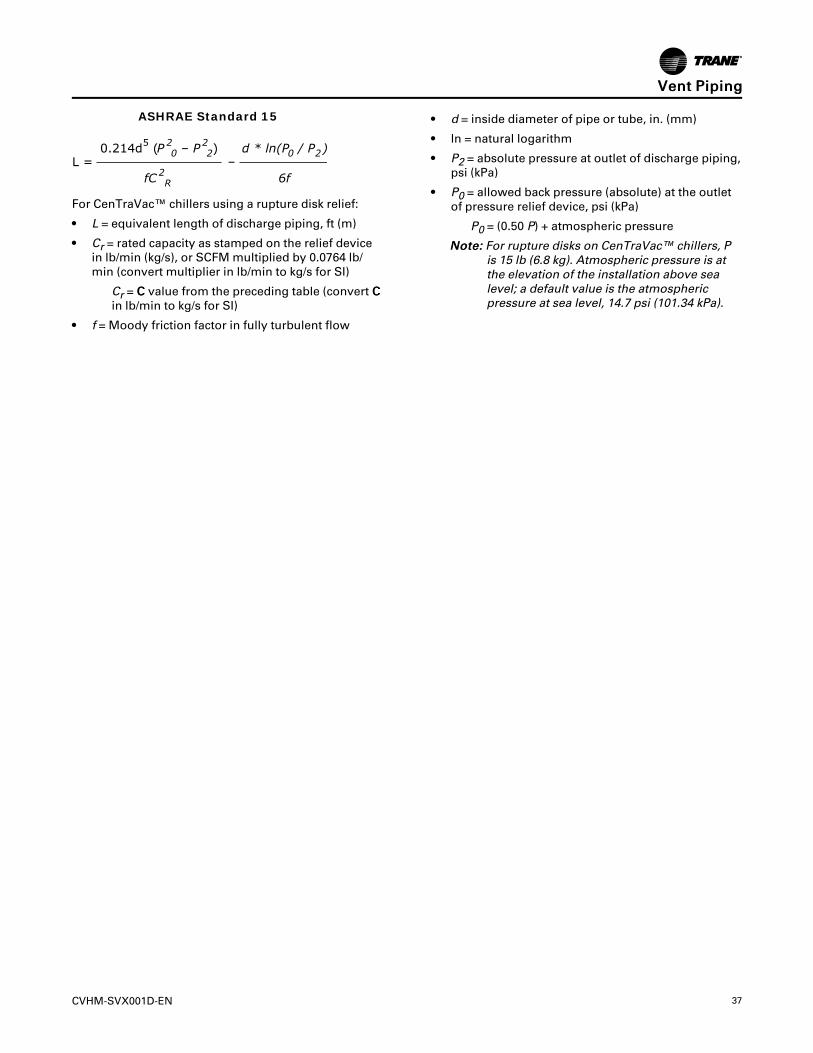
CVHM-SVX001D-EN 37
L =0.214d5 (P 2
0 – P 22)
–d * ln(P0 / P2)
fC 2R 6f
ASHRAE Standard 15
For CenTraVac™ chillers using a rupture disk relief:
• L = equivalent length of discharge piping, ft (m)
• Cr = rated capacity as stamped on the relief devicein lb/min (kg/s), or SCFM multiplied by 0.0764 lb/min (convert multiplier in lb/min to kg/s for SI)
Cr = CC value from the preceding table (convert CCin lb/min to kg/s for SI)
• f = Moody friction factor in fully turbulent flow
• d = inside diameter of pipe or tube, in. (mm)
• ln = natural logarithm
• P2 = absolute pressure at outlet of discharge piping,psi (kPa)
• P0 = allowed back pressure (absolute) at the outletof pressure relief device, psi (kPa)
P0 = (0.50 P) + atmospheric pressure
NNoottee:: For rupture disks on CenTraVac™ chillers, Pis 15 lb (6.8 kg). Atmospheric pressure is atthe elevation of the installation above sealevel; a default value is the atmosphericpressure at sea level, 14.7 psi (101.34 kPa).
VVeenntt PPiippiinngg
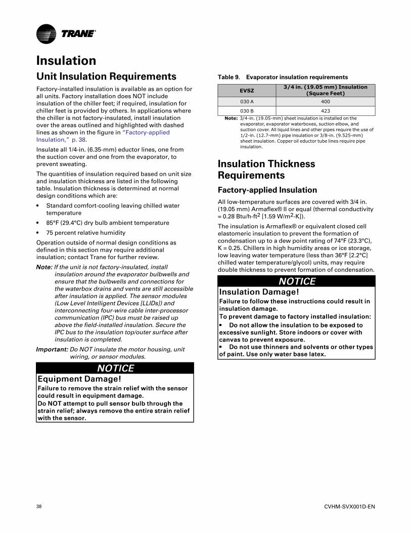
38 CVHM-SVX001D-EN
InsulationUnit Insulation RequirementsFactory-installed insulation is available as an option forall units. Factory installation does NOT includeinsulation of the chiller feet; if required, insulation forchiller feet is provided by others. In applications wherethe chiller is not factory-insulated, install insulationover the areas outlined and highlighted with dashedlines as shown in the figure in “Factory-appliedInsulation,” p. 38.
Insulate all 1/4-in. (6.35-mm) eductor lines, one fromthe suction cover and one from the evaporator, toprevent sweating.
The quantities of insulation required based on unit sizeand insulation thickness are listed in the followingtable. Insulation thickness is determined at normaldesign conditions which are:
• Standard comfort-cooling leaving chilled watertemperature
• 85°F (29.4°C) dry bulb ambient temperature
• 75 percent relative humidity
Operation outside of normal design conditions asdefined in this section may require additionalinsulation; contact Trane for further review.
NNoottee:: If the unit is not factory-insulated, installinsulation around the evaporator bulbwells andensure that the bulbwells and connections forthe waterbox drains and vents are still accessibleafter insulation is applied. The sensor modules(Low Level Intelligent Devices [LLIDs]) andinterconnecting four-wire cable inter-processorcommunication (IPC) bus must be raised upabove the field-installed insulation. Secure theIPC bus to the insulation top/outer surface afterinsulation is completed.
IImmppoorrttaanntt:: Do NOT insulate the motor housing, unitwiring, or sensor modules.
NNOOTTIICCEEEEqquuiippmmeenntt DDaammaaggee!!FFaaiilluurree ttoo rreemmoovvee tthhee ssttrraaiinn rreelliieeff wwiitthh tthhee sseennssoorrccoouulldd rreessuulltt iinn eeqquuiippmmeenntt ddaammaaggee..DDoo NNOOTT aatttteemmpptt ttoo ppuullll sseennssoorr bbuullbb tthhrroouugghh tthheessttrraaiinn rreelliieeff;; aallwwaayyss rreemmoovvee tthhee eennttiirree ssttrraaiinn rreelliieeffwwiitthh tthhee sseennssoorr..
Table 9. Evaporator insulation requirements
EVSZ3/4 in. (19.05mm) Insulation
(Square Feet)030 A 400
030 B 423Note: 3/4-in. (19.05-mm) sheet insulation is installed on the
evaporator, evaporator waterboxes, suction elbow, andsuction cover. All liquid lines and other pipes require the use of1/2-in. (12.7-mm) pipe insulation or 3/8-in. (9.525-mm)sheet insulation. Copper oil eductor tube lines require pipeinsulation.
Insulation ThicknessRequirementsFactory-applied InsulationAll low-temperature surfaces are covered with 3/4 in.(19.05 mm) Armaflex® II or equal (thermal conductivity= 0.28 Btu/h-ft2 [1.59 W/m2-K]).
The insulation is Armaflex® or equivalent closed cellelastomeric insulation to prevent the formation ofcondensation up to a dew point rating of 74°F (23.3°C),K = 0.25. Chillers in high humidity areas or ice storage,low leaving water temperature (less than 36°F [2.2°C]chilled water temperature/glycol) units, may requiredouble thickness to prevent formation of condensation.
NNOOTTIICCEEIInnssuullaattiioonn DDaammaaggee!!FFaaiilluurree ttoo ffoollllooww tthheessee iinnssttrruuccttiioonnss ccoouulldd rreessuulltt iinniinnssuullaattiioonn ddaammaaggee..TToo pprreevveenntt ddaammaaggee ttoo ffaaccttoorryy iinnssttaalllleedd iinnssuullaattiioonn::•• DDoo nnoott aallllooww tthhee iinnssuullaattiioonn ttoo bbee eexxppoosseedd ttooeexxcceessssiivvee ssuunnlliigghhtt.. SSttoorree iinnddoooorrss oorr ccoovveerr wwiitthhccaannvvaass ttoo pprreevveenntt eexxppoossuurree..•• DDoo nnoott uussee tthhiinnnneerrss aanndd ssoollvveennttss oorr ootthheerr ttyyppeessooff ppaaiinntt.. UUssee oonnllyy wwaatteerr bbaassee llaatteexx..
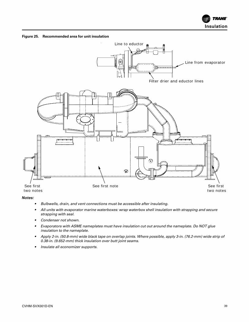
CVHM-SVX001D-EN 39
Figure 25. Recommended area for unit insulation
See first two notes
See first two notes
See first note
Line from evaporator
Line to eductor
Filter drier and eductor lines
NNootteess::
• Bulbwells, drain, and vent connections must be accessible after insulating.
• All units with evaporator marine waterboxes: wrap waterbox shell insulation with strapping and securestrapping with seal.
• Condenser not shown.
• Evaporators with ASME nameplates must have insulation cut out around the nameplate. Do NOT glueinsulation to the nameplate.
• Apply 2-in. (50.8-mm) wide black tape on overlap joints. Where possible, apply 3-in. (76.2-mm) wide strip of0.38-in. (9.652-mm) thick insulation over butt joint seams.
• Insulate all economizer supports.
IInnssuullaattiioonn

40 CVHM-SVX001D-EN
Installation: ControlsThis section covers information pertaining to theUC800 controller hardware. For information about theTracer® AdaptiView™ display, which is used tointerface with the internal chiller data and functionsprovided by the UC800, refer to Tracer AdaptiViewDisplay for Water-cooled CenTraVac ChillersOperations Guide (CTV-SVU01*-EN).
UC800 SpecificationsPower SupplyThe UC800 (1A22) receives 24 Vac (210 mA) powerfrom the 1A2 power supply located in the chiller controlpanel.
Wiring and Port DescriptionsThe following figure illustrates the UC800 controllerports, LEDs, rotary switches, and wiring terminals. Thenumbered list following the figure corresponds to thenumbered callouts in the illustration.
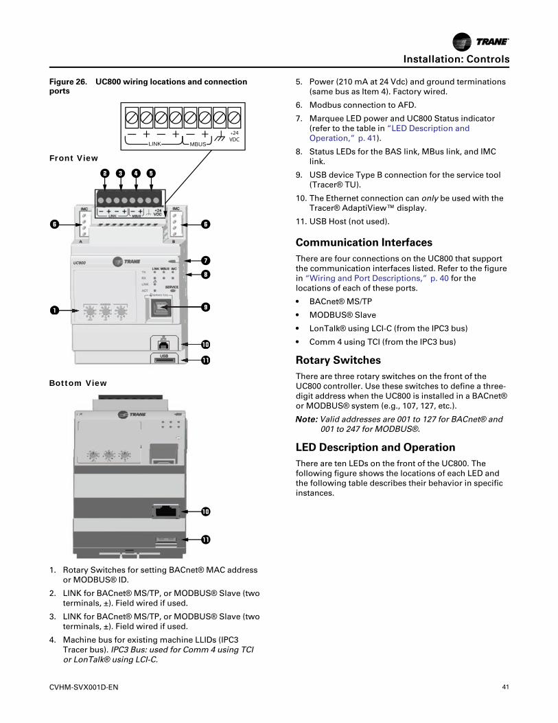
CVHM-SVX001D-EN 41
Figure 26. UC800 wiring locations and connectionports
LINK
+ + +24VDC
+MBUS
1
2 3 4 5
6
78
9
0-
6
11 99
00--
0
-
Front View
Bottom View
1. Rotary Switches for setting BACnet® MAC addressor MODBUS® ID.
2. LINK for BACnet® MS/TP, or MODBUS® Slave (twoterminals, ±). Field wired if used.
3. LINK for BACnet® MS/TP, or MODBUS® Slave (twoterminals, ±). Field wired if used.
4. Machine bus for existing machine LLIDs (IPC3Tracer bus). IPC3 Bus: used for Comm 4 using TCIor LonTalk® using LCI-C.
5. Power (210 mA at 24 Vdc) and ground terminations(same bus as Item 4). Factory wired.
6. Modbus connection to AFD.
7. Marquee LED power and UC800 Status indicator(refer to the table in “LED Description andOperation,” p. 41).
8. Status LEDs for the BAS link, MBus link, and IMClink.
9. USB device Type B connection for the service tool(Tracer® TU).
10. The Ethernet connection can only be used with theTracer® AdaptiView™ display.
11. USB Host (not used).
Communication InterfacesThere are four connections on the UC800 that supportthe communication interfaces listed. Refer to the figurein “Wiring and Port Descriptions,” p. 40 for thelocations of each of these ports.
• BACnet® MS/TP
• MODBUS® Slave
• LonTalk® using LCI-C (from the IPC3 bus)
• Comm 4 using TCI (from the IPC3 bus)
Rotary SwitchesThere are three rotary switches on the front of theUC800 controller. Use these switches to define a three-digit address when the UC800 is installed in a BACnet®or MODBUS® system (e.g., 107, 127, etc.).
NNoottee:: Valid addresses are 001 to 127 for BACnet® and001 to 247 for MODBUS®.
LED Description and OperationThere are ten LEDs on the front of the UC800. Thefollowing figure shows the locations of each LED andthe following table describes their behavior in specificinstances.
IInnssttaallllaattiioonn:: CCoonnttrroollss
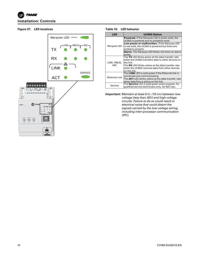
42 CVHM-SVX001D-EN
Figure 27. LED locations
LINK
LINK MBUS IMC
TX
RX
ACTSERVICE
Marquee LED
Table 10. LED behavior
LED UC800 Status
Marquee LED
Powered. If the Marquee LED is green solid, theUC800 is powered and no problems exist.Low power or malfunction. If the Marquee LEDis red solid, the UC800 is powered but there areproblems present.Alarm. The Marquee LED blinks red when an alarmexists.
LINK, MBUS,IMC
The TX LED blinks green at the data transfer ratewhen the UC800 transfers data to other devices onthe link.The RX LED blinks yellow at the data transfer ratewhen the UC800 receives data from other deviceson the link.
Ethernet Link
The LINK LED is solid green if the Ethernet link isconnected and communicating.The ACT LED blinks yellow at the data transfer ratewhen data flow is active on the link.
ServiceThe Service LED is solid green when pressed. Forqualified service technicians only. Do NOTuse.
IImmppoorrttaanntt:: Maintain at least 6 in. (16 cm) between low-voltage (less than 30V) and high voltagecircuits. Failure to do so could result inelectrical noise that could distort thesignals carried by the low-voltage wiring,including inter-processor communication(IPC).
IInnssttaallllaattiioonn:: CCoonnttrroollss
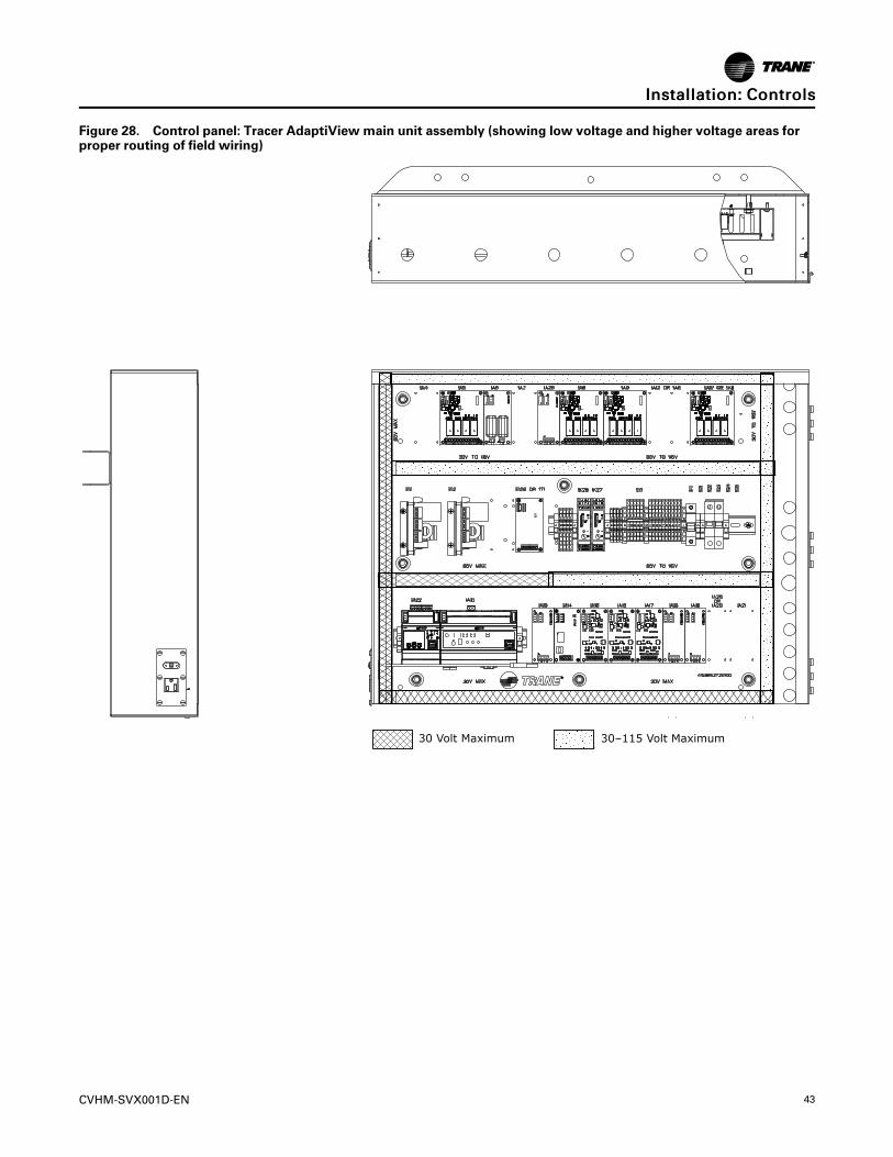
CVHM-SVX001D-EN 43
Figure 28. Control panel: Tracer AdaptiView main unit assembly (showing low voltage and higher voltage areas forproper routing of field wiring)
30 Volt Maximum 30–115 Volt Maximum
IInnssttaallllaattiioonn:: CCoonnttrroollss
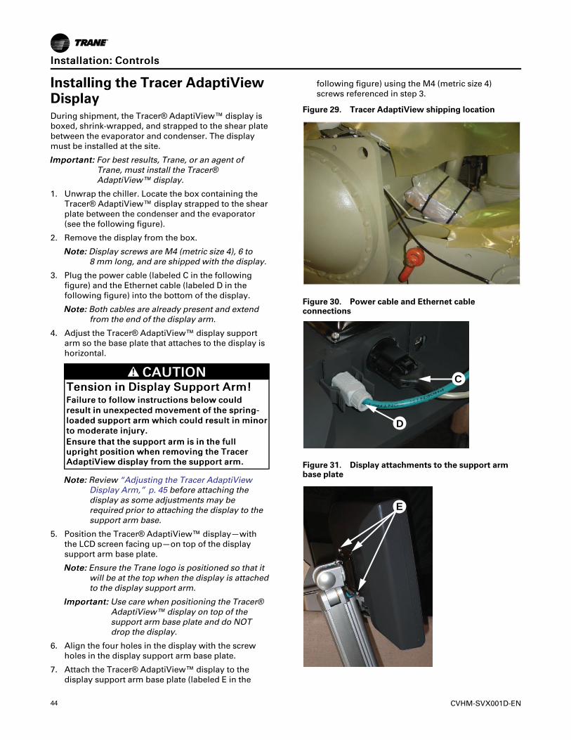
44 CVHM-SVX001D-EN
Installing the Tracer AdaptiViewDisplayDuring shipment, the Tracer® AdaptiView™ display isboxed, shrink-wrapped, and strapped to the shear platebetween the evaporator and condenser. The displaymust be installed at the site.
IImmppoorrttaanntt:: For best results, Trane, or an agent ofTrane, must install the Tracer®AdaptiView™ display.
1. Unwrap the chiller. Locate the box containing theTracer® AdaptiView™ display strapped to the shearplate between the condenser and the evaporator(see the following figure).
2. Remove the display from the box.
NNoottee:: Display screws are M4 (metric size 4), 6 to8 mm long, and are shipped with the display.
3. Plug the power cable (labeled C in the followingfigure) and the Ethernet cable (labeled D in thefollowing figure) into the bottom of the display.
NNoottee:: Both cables are already present and extendfrom the end of the display arm.
4. Adjust the Tracer® AdaptiView™ display supportarm so the base plate that attaches to the display ishorizontal.
CCAAUUTTIIOONNTTeennssiioonn iinn DDiissppllaayy SSuuppppoorrtt AArrmm!!FFaaiilluurree ttoo ffoollllooww iinnssttrruuccttiioonnss bbeellooww ccoouullddrreessuulltt iinn uunneexxppeecctteedd mmoovveemmeenntt ooff tthhee sspprriinngg--llooaaddeedd ssuuppppoorrtt aarrmm wwhhiicchh ccoouulldd rreessuulltt iinn mmiinnoorrttoo mmooddeerraattee iinnjjuurryy..EEnnssuurree tthhaatt tthhee ssuuppppoorrtt aarrmm iiss iinn tthhee ffuulllluupprriigghhtt ppoossiittiioonn wwhheenn rreemmoovviinngg tthhee TTrraacceerrAAddaappttiiVViieeww ddiissppllaayy ffrroomm tthhee ssuuppppoorrtt aarrmm..
NNoottee:: Review “Adjusting the Tracer AdaptiViewDisplay Arm,” p. 45 before attaching thedisplay as some adjustments may berequired prior to attaching the display to thesupport arm base.
5. Position the Tracer® AdaptiView™ display—withthe LCD screen facing up—on top of the displaysupport arm base plate.
NNoottee:: Ensure the Trane logo is positioned so that itwill be at the top when the display is attachedto the display support arm.
IImmppoorrttaanntt:: Use care when positioning the Tracer®AdaptiView™ display on top of thesupport arm base plate and do NOTdrop the display.
6. Align the four holes in the display with the screwholes in the display support arm base plate.
7. Attach the Tracer® AdaptiView™ display to thedisplay support arm base plate (labeled E in the
following figure) using the M4 (metric size 4)screws referenced in step 3.
Figure 29. Tracer AdaptiView shipping location
Figure 30. Power cable and Ethernet cableconnections
D
C
Figure 31. Display attachments to the support armbase plate
E
IInnssttaallllaattiioonn:: CCoonnttrroollss
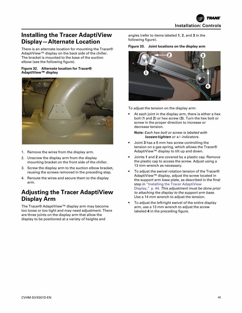
CVHM-SVX001D-EN 45
Installing the Tracer AdaptiViewDisplay—Alternate LocationThere is an alternate location for mounting the Tracer®AdaptiView™ display on the back side of the chiller.The bracket is mounted to the base of the suctionelbow (see the following figure).
Figure 32. Alternate location for Tracer®®AdaptiView™™ display
1. Remove the wires from the display arm.
2. Unscrew the display arm from the displaymounting bracket on the front side of the chiller.
3. Screw the display arm to the suction elbow bracket,reusing the screws removed in the preceding step.
4. Reroute the wires and secure them to the displayarm.
Adjusting the Tracer AdaptiViewDisplay ArmThe Tracer® AdaptiView™ display arm may becometoo loose or too tight and may need adjustment. Thereare three joints on the display arm that allow thedisplay to be positioned at a variety of heights and
angles (refer to items labeled 11, 22, and 33 in thefollowing figure).
Figure 33. Joint locations on the display arm
1
2 3
4
To adjust the tension on the display arm:
• At each joint in the display arm, there is either a hexbolt (11 and 22) or hex screw (33). Turn the hex bolt orscrew in the proper direction to increase ordecrease tension.
NNoottee:: Each hex bolt or screw is labeled withlloooosseenn/ttiigghhtteenn or ++/-- indicators.
• Joint 33 has a 6 mm hex screw controlling thetension on a gas spring, which allows the Tracer®AdaptiView™ display to tilt up and down.
• Joints 11 and 22 are covered by a plastic cap. Removethe plastic cap to access the screw. Adjust using a13 mm wrench as necessary.
• To adjust the swivel rotation tension of the Tracer®AdaptiView™ display, adjust the screw located inthe support arm base plate, as described in the finalstep in “Installing the Tracer AdaptiViewDisplay,” p. 44. This adjustment must be done priorto attaching the display to the support arm base.Use a 14 mm wrench to adjust the tension.
• To adjust the left/right swivel of the entire displayarm, use a 13 mm wrench to adjust the screwlabeled 44 in the preceding figure.
IInnssttaallllaattiioonn:: CCoonnttrroollss
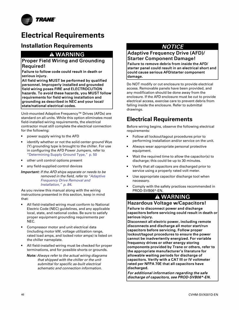
46 CVHM-SVX001D-EN
Electrical RequirementsInstallation Requirements
WWAARRNNIINNGGPPrrooppeerr FFiieelldd WWiirriinngg aanndd GGrroouunnddiinnggRReeqquuiirreedd!!FFaaiilluurree ttoo ffoollllooww ccooddee ccoouulldd rreessuulltt iinn ddeeaatthh oorrsseerriioouuss iinnjjuurryy..AAllll ffiieelldd wwiirriinngg MMUUSSTT bbee ppeerrffoorrmmeedd bbyy qquuaalliiffiieeddppeerrssoonnnneell.. IImmpprrooppeerrllyy iinnssttaalllleedd aanndd ggrroouunnddeeddffiieelldd wwiirriinngg ppoosseess FFIIRREE aanndd EELLEECCTTRROOCCUUTTIIOONNhhaazzaarrddss.. TToo aavvooiidd tthheessee hhaazzaarrddss,, yyoouu MMUUSSTT ffoolllloowwrreeqquuiirreemmeennttss ffoorr ffiieelldd wwiirriinngg iinnssttaallllaattiioonn aannddggrroouunnddiinngg aass ddeessccrriibbeedd iinn NNEECC aanndd yyoouurr llooccaall//ssttaattee//nnaattiioonnaall eelleeccttrriiccaall ccooddeess..
Unit-mounted Adaptive Frequency™ Drives (AFDs) arestandard on all units. While this option eliminates mostfield-installed wiring requirements, the electricalcontractor must still complete the electrical connectionfor the following:
• power supply wiring to the AFD
• identify whether or not the solid center ground Wye(Y) grounding type is brought to the chiller. For usein configuring the AFD Power Jumpers, refer to“Determining Supply Ground Type,” p. 50
• other unit control options present
• any field-supplied control devices
IImmppoorrttaanntt:: If the AFD ships separate or needs to beremoved in the field, refer to “AdaptiveFrequency Drive Removal andInstallation,” p. 84.
As you review this manual along with the wiringinstructions presented in this section, keep in mindthat:
• All field-installed wiring must conform to NationalElectric Code (NEC) guidelines, and any applicablelocal, state, and national codes. Be sure to satisfyproper equipment grounding requirements perNEC.
• Compressor motor and unit electrical data(including motor kW, voltage utilization range,rated load amps, and locked rotor amps) is listed onthe chiller nameplate.
• All field-installed wiring must be checked for properterminations, and for possible shorts or grounds.
NNoottee:: Always refer to the actual wiring diagramsthat shipped with the chiller or the unitsubmittal for specific as-built electricalschematic and connection information.
NNOOTTIICCEEAAddaappttiivvee FFrreeqquueennccyy DDrriivvee ((AAFFDD))//SSttaarrtteerr CCoommppoonneenntt DDaammaaggee!!FFaaiilluurree ttoo rreemmoovvee ddeebbrriiss ffrroomm iinnssiiddee tthhee AAFFDD//ssttaarrtteerr ppaanneell ccoouulldd rreessuulltt iinn aann eelleeccttrriiccaall sshhoorrtt aannddccoouulldd ccaauussee sseerriioouuss AAFFDD//ssttaarrtteerr ccoommppoonneennttddaammaaggee..
Do NOT modify or cut enclosure to provide electricalaccess. Removable panels have been provided, andany modification should be done away from theenclosure. If the AFD enclosure must be cut to provideelectrical access, exercise care to prevent debris fromfalling inside the enclosure. Refer to submittaldrawings.
Electrical RequirementsBefore wiring begins, observe the following electricalrequirements:
• Follow all lockout/tagout procedures prior toperforming installation and/or service on the unit.
• Always wear appropriate personal protectiveequipment.
• Wait the required time to allow the capacitor(s) todischarge; this could be up to 30 minutes.
• Verify that all capacitors are discharged prior toservice using a properly rated volt meter.
• Use appropriate capacitor discharge tool whennecessary.
• Comply with the safety practices recommended inPROD-SVB06*-EN.
WWAARRNNIINNGGHHaazzaarrddoouuss VVoollttaaggee ww//CCaappaacciittoorrss!!FFaaiilluurree ttoo ddiissccoonnnneecctt ppoowweerr aanndd ddiisscchhaarrggeeccaappaacciittoorrss bbeeffoorree sseerrvviicciinngg ccoouulldd rreessuulltt iinn ddeeaatthh oorrsseerriioouuss iinnjjuurryy..DDiissccoonnnneecctt aallll eelleeccttrriicc ppoowweerr,, iinncclluuddiinngg rreemmootteeddiissccoonnnneeccttss aanndd ddiisscchhaarrggee aallll mmoottoorr ssttaarrtt//rruunnccaappaacciittoorrss bbeeffoorree sseerrvviicciinngg.. FFoollllooww pprrooppeerrlloocckkoouutt//ttaaggoouutt pprroocceedduurreess ttoo eennssuurree tthhee ppoowweerrccaannnnoott bbee iinnaaddvveerrtteennttllyy eenneerrggiizzeedd.. FFoorr vvaarriiaabblleeffrreeqquueennccyy ddrriivveess oorr ootthheerr eenneerrggyy ssttoorriinnggccoommppoonneennttss pprroovviiddeedd bbyy TTrraannee oorr ootthheerrss,, rreeffeerr ttootthhee aapppprroopprriiaattee mmaannuuffaaccttuurreerr’’ss lliitteerraattuurree ffoorraalllloowwaabbllee wwaaiittiinngg ppeerriiooddss ffoorr ddiisscchhaarrggee ooffccaappaacciittoorrss.. VVeerriiffyy wwiitthh aa CCAATT IIIIII oorr IIVV vvoollttmmeetteerrrraatteedd ppeerr NNFFPPAA 7700EE tthhaatt aallll ccaappaacciittoorrss hhaavveeddiisscchhaarrggeedd..FFoorr aaddddiittiioonnaall iinnffoorrmmaattiioonn rreeggaarrddiinngg tthhee ssaaffeeddiisscchhaarrggee ooff ccaappaacciittoorrss,, sseeee PPRROODD--SSVVBB0066**--EENN..
CVHM-SVX001D-EN 47
WWAARRNNIINNGGPPeerrssoonnaall PPrrootteeccttiivvee EEqquuiippmmeenntt ((PPPPEE))RReeqquuiirreedd!!FFaaiilluurree ttoo wweeaarr PPPPEE aanndd ffoollllooww pprrooppeerr hhaannddlliinngggguuiiddeelliinneess ccoouulldd rreessuulltt iinn ddeeaatthh oorr sseerriioouuss iinnjjuurryy..AAllwwaayyss wweeaarr aapppprroopprriiaattee ppeerrssoonnaall pprrootteeccttiivveeeeqquuiippmmeenntt iinn aaccccoorrddaannccee wwiitthh aapppplliiccaabblleerreegguullaattiioonnss aanndd//oorr ssttaannddaarrddss ttoo gguuaarrdd aaggaaiinnssttppootteennttiiaall eelleeccttrriiccaall sshhoocckk aanndd ffllaasshh hhaazzaarrddss..
WWAARRNNIINNGGLLiivvee EElleeccttrriiccaall CCoommppoonneennttss!!FFaaiilluurree ttoo ffoollllooww aallll eelleeccttrriiccaall ssaaffeettyy pprreeccaauuttiioonnsswwhheenn eexxppoosseedd ttoo lliivvee eelleeccttrriiccaall ccoommppoonneennttss ccoouullddrreessuulltt iinn ddeeaatthh oorr sseerriioouuss iinnjjuurryy..WWhheenn iitt iiss nneecceessssaarryy ttoo wwoorrkk wwiitthh lliivvee eelleeccttrriiccaallccoommppoonneennttss,, hhaavvee aa qquuaalliiffiieedd lliicceennsseedd eelleeccttrriicciiaannoorr ootthheerr iinnddiivviidduuaall wwhhoo hhaass bbeeeenn pprrooppeerrllyy ttrraaiinneeddiinn hhaannddlliinngg lliivvee eelleeccttrriiccaall ccoommppoonneennttss ppeerrffoorrmmtthheessee ttaasskkss..
EElleeccttrriiccaall RReeqquuiirreemmeennttss
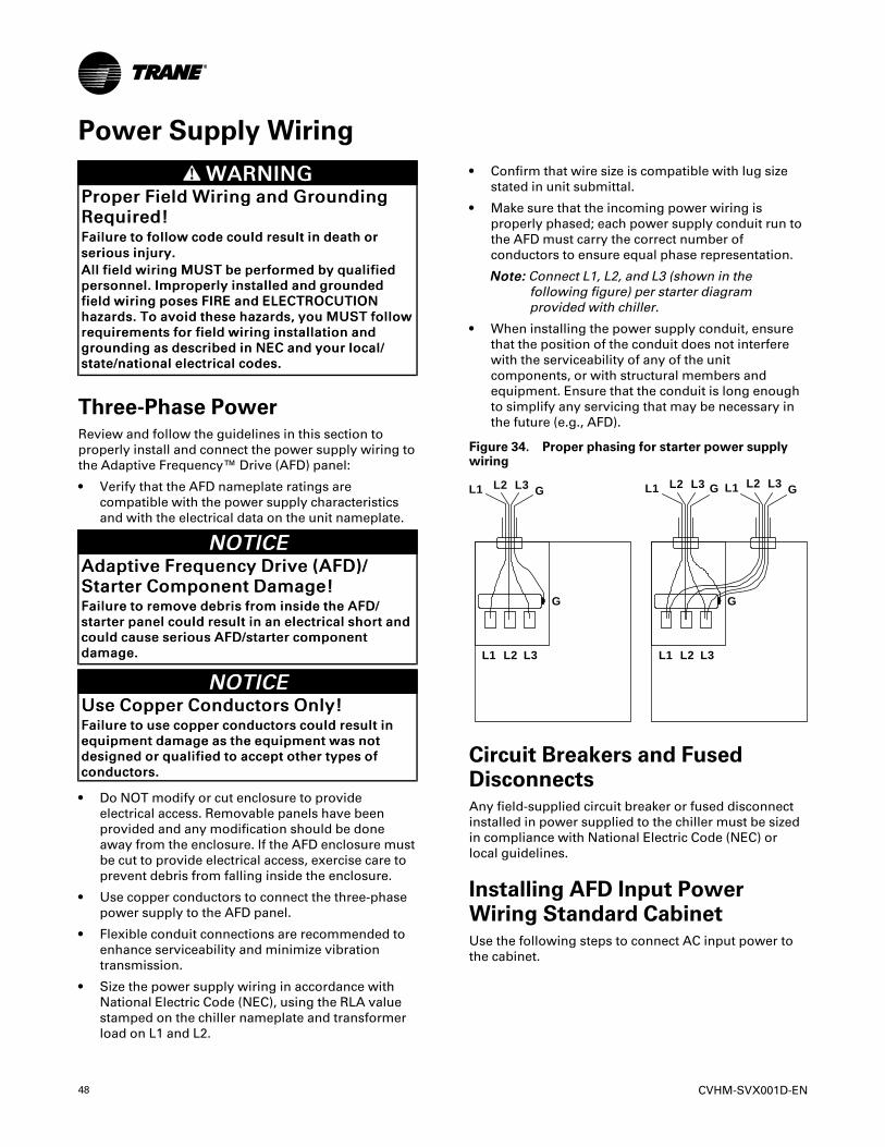
48 CVHM-SVX001D-EN
Power Supply WiringWWAARRNNIINNGG
PPrrooppeerr FFiieelldd WWiirriinngg aanndd GGrroouunnddiinnggRReeqquuiirreedd!!FFaaiilluurree ttoo ffoollllooww ccooddee ccoouulldd rreessuulltt iinn ddeeaatthh oorrsseerriioouuss iinnjjuurryy..AAllll ffiieelldd wwiirriinngg MMUUSSTT bbee ppeerrffoorrmmeedd bbyy qquuaalliiffiieeddppeerrssoonnnneell.. IImmpprrooppeerrllyy iinnssttaalllleedd aanndd ggrroouunnddeeddffiieelldd wwiirriinngg ppoosseess FFIIRREE aanndd EELLEECCTTRROOCCUUTTIIOONNhhaazzaarrddss.. TToo aavvooiidd tthheessee hhaazzaarrddss,, yyoouu MMUUSSTT ffoolllloowwrreeqquuiirreemmeennttss ffoorr ffiieelldd wwiirriinngg iinnssttaallllaattiioonn aannddggrroouunnddiinngg aass ddeessccrriibbeedd iinn NNEECC aanndd yyoouurr llooccaall//ssttaattee//nnaattiioonnaall eelleeccttrriiccaall ccooddeess..
Three-Phase PowerReview and follow the guidelines in this section toproperly install and connect the power supply wiring tothe Adaptive Frequency™ Drive (AFD) panel:
• Verify that the AFD nameplate ratings arecompatible with the power supply characteristicsand with the electrical data on the unit nameplate.
NNOOTTIICCEEAAddaappttiivvee FFrreeqquueennccyy DDrriivvee ((AAFFDD))//SSttaarrtteerr CCoommppoonneenntt DDaammaaggee!!FFaaiilluurree ttoo rreemmoovvee ddeebbrriiss ffrroomm iinnssiiddee tthhee AAFFDD//ssttaarrtteerr ppaanneell ccoouulldd rreessuulltt iinn aann eelleeccttrriiccaall sshhoorrtt aannddccoouulldd ccaauussee sseerriioouuss AAFFDD//ssttaarrtteerr ccoommppoonneennttddaammaaggee..
NNOOTTIICCEEUUssee CCooppppeerr CCoonndduuccttoorrss OOnnllyy!!FFaaiilluurree ttoo uussee ccooppppeerr ccoonndduuccttoorrss ccoouulldd rreessuulltt iinneeqquuiippmmeenntt ddaammaaggee aass tthhee eeqquuiippmmeenntt wwaass nnoottddeessiiggnneedd oorr qquuaalliiffiieedd ttoo aacccceepptt ootthheerr ttyyppeess ooffccoonndduuccttoorrss..
• Do NOT modify or cut enclosure to provideelectrical access. Removable panels have beenprovided and any modification should be doneaway from the enclosure. If the AFD enclosure mustbe cut to provide electrical access, exercise care toprevent debris from falling inside the enclosure.
• Use copper conductors to connect the three-phasepower supply to the AFD panel.
• Flexible conduit connections are recommended toenhance serviceability and minimize vibrationtransmission.
• Size the power supply wiring in accordance withNational Electric Code (NEC), using the RLA valuestamped on the chiller nameplate and transformerload on L1 and L2.
• Confirm that wire size is compatible with lug sizestated in unit submittal.
• Make sure that the incoming power wiring isproperly phased; each power supply conduit run tothe AFD must carry the correct number ofconductors to ensure equal phase representation.
NNoottee:: Connect L1, L2, and L3 (shown in thefollowing figure) per starter diagramprovided with chiller.
• When installing the power supply conduit, ensurethat the position of the conduit does not interferewith the serviceability of any of the unitcomponents, or with structural members andequipment. Ensure that the conduit is long enoughto simplify any servicing that may be necessary inthe future (e.g., AFD).
Figure 34. Proper phasing for starter power supplywiring
L1 L2 L3 G L1 L2 L3 G L1 L2 L3 G
G G
L1 L2 L3 L1 L2 L3
Circuit Breakers and FusedDisconnectsAny field-supplied circuit breaker or fused disconnectinstalled in power supplied to the chiller must be sizedin compliance with National Electric Code (NEC) orlocal guidelines.
Installing AFD Input PowerWiring Standard CabinetUse the following steps to connect AC input power tothe cabinet.
CVHM-SVX001D-EN 49
WWAARRNNIINNGGHHaazzaarrddoouuss VVoollttaaggee ww//CCaappaacciittoorrss!!FFaaiilluurree ttoo ddiissccoonnnneecctt ppoowweerr aanndd ddiisscchhaarrggeeccaappaacciittoorrss bbeeffoorree sseerrvviicciinngg ccoouulldd rreessuulltt iinn ddeeaatthh oorrsseerriioouuss iinnjjuurryy..DDiissccoonnnneecctt aallll eelleeccttrriicc ppoowweerr,, iinncclluuddiinngg rreemmootteeddiissccoonnnneeccttss aanndd ddiisscchhaarrggee aallll mmoottoorr ssttaarrtt//rruunnccaappaacciittoorrss bbeeffoorree sseerrvviicciinngg.. FFoollllooww pprrooppeerrlloocckkoouutt//ttaaggoouutt pprroocceedduurreess ttoo eennssuurree tthhee ppoowweerrccaannnnoott bbee iinnaaddvveerrtteennttllyy eenneerrggiizzeedd.. FFoorr vvaarriiaabblleeffrreeqquueennccyy ddrriivveess oorr ootthheerr eenneerrggyy ssttoorriinnggccoommppoonneennttss pprroovviiddeedd bbyy TTrraannee oorr ootthheerrss,, rreeffeerr ttootthhee aapppprroopprriiaattee mmaannuuffaaccttuurreerr’’ss lliitteerraattuurree ffoorraalllloowwaabbllee wwaaiittiinngg ppeerriiooddss ffoorr ddiisscchhaarrggee ooffccaappaacciittoorrss.. VVeerriiffyy wwiitthh aa CCAATT IIIIII oorr IIVV vvoollttmmeetteerrrraatteedd ppeerr NNFFPPAA 7700EE tthhaatt aallll ccaappaacciittoorrss hhaavveeddiisscchhaarrggeedd..FFoorr aaddddiittiioonnaall iinnffoorrmmaattiioonn rreeggaarrddiinngg tthhee ssaaffeeddiisscchhaarrggee ooff ccaappaacciittoorrss,, sseeee PPRROODD--SSVVBB0066**--EENN..
1. Turn off, lock out, and tag the input power to thedrive.
2. Remove the panel from the top left of the driveenclosure.
NNOOTTIICCEEEEqquuiippmmeenntt FFaaiilluurree!!DDeebbrriiss ffaalllliinngg iinnssiiddee ooff aaddaappttiivvee ffrreeqquueennccyyddrriivvee ccoouulldd ccaauussee ffaaiilluurree ooff eelleeccttrroonniiccccoommppoonneennttss..DDoo nnoott ccuutt hhoolleess iinn aaddaappttiivvee ffrreeqquueennccyy ddrriivveeeenncclloossuurree..
3. After removing the panel, drill the wire routingholes in the panel. These wire routing holes are theonly entry points for input power wiring into thecabinet.
4. Install the appropriate conduit hubs.
5. Reinstall the cabinet’s top panel.
6. Connect the three-phase input power leads tocircuit breaker terminals L1, L2, and L3. Tightenthese connections to 275 in·lb (31.1 N·m). Use onlycopper-conductors for the input power leads.
Input power wiring should be copper and should besized according to applicable codes to handle thedrive’s continuous rated input current.
Refer to submittals for power lug sizes and locationalong with control wiring specifics for the controller.
IImmppoorrttaanntt:: Power connections should be re-torquedafter the first three to six months ofoperation and on an annual basisthereafter.
Torquing Electrical Power ConnectionsUse a torque wrench to tighten power connections. Atorque wrench eliminates the human element andprovides proper hardware tightening.
Proper torque for connections depends on both thescrew materials and the metals being connected.Strand migration will occur when the copper is underprolonged pressure.
Electrical power terminations should be rechecked fortightness when the apparatus is first installed andperiodically afterwards. The conductor could flowunder prolonged pressure. Thermal cycling will begreater during the first few months in operation.
Most hardware used for making a screwed electricaljoint will be low carbon steel. The hardware does notcarry electrical current but holds the two conductingsurfaces together under pressure. When properlytorqued, the slight elongation of the screw acts tomaintain pressure on the electrical joint. The thermalexpansion of steel is less than that of the conductingmetals, which is usually copper.
The pressure at the electrical joint will vary slightlyduring thermal cycling and reduces somewhat whenthere is cold flow in the conducting metals. Re-torquingwill re-establish the surface pressure, which is essentialto keeping a low resistance drop between the twoconducting surfaces and avoiding eventual failure.
NNoottee:: Connection from the Adaptive Frequency™ Drive(AFD) output to the motor is made with flexiblecable. PROPER TORQUE IS CRITICAL. Refer tothe label inside the AFD cabinet for propertorque values.
NNOOTTIICCEEEEqquuiippmmeenntt DDaammaaggee!!FFaaiilluurree ttoo ffoollllooww iinnssttrruuccttiioonnss bbeellooww ccoouulldd rreessuulltt iinneeqquuiippmmeenntt ddaammaaggee..TThhee IIGGBBTTss aarree ccoonnnneecctteedd ttoo tthhee ootthheerr eenndd ooff tthheetteerrmmiinnaall bbaarr.. WWhheenn ttiigghhtteenniinngg ccoonnnneeccttiioonnss aatt tthheeddrriivvee tteerrmmiinnaallss,, ttaakkee ccaarree ttoo aavvooiidd ssttrreessssiinngg tthheeIIGGBBTTss..
Cabinet Wire RoutingAll wiring should be installed in conformance with theapplicable local, state, national, and international codes(for example, NEC/CEC). Control wiring enters thecabinet through the right side and terminates at thedrive panel’s terminal block. Tighten the control wireconnections to 7.1 to 8.9 in·lb (0.8 to 1.0 N·m).
Grounding the CabinetNNoottee:: Follow applicable codes! The user is responsible
for conforming to all applicable local, national,and international codes. Failure to observe thisprecaution could result in damage to, ordestruction of, the equipment.
PPoowweerr SSuuppppllyy WWiirriinngg
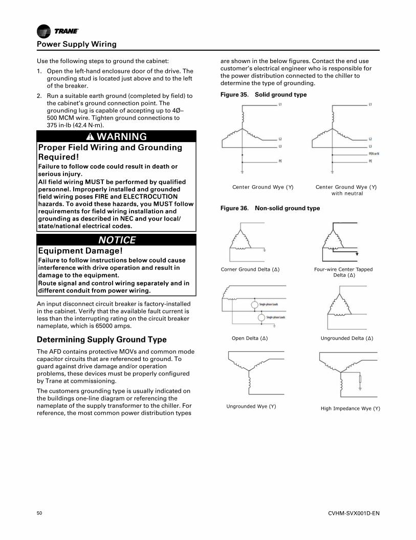
50 CVHM-SVX001D-EN
Use the following steps to ground the cabinet:
1. Open the left-hand enclosure door of the drive. Thegrounding stud is located just above and to the leftof the breaker.
2. Run a suitable earth ground (completed by field) tothe cabinet’s ground connection point. Thegrounding lug is capable of accepting up to 4Ø–500 MCM wire. Tighten ground connections to375 in·lb (42.4 N·m).
WWAARRNNIINNGGPPrrooppeerr FFiieelldd WWiirriinngg aanndd GGrroouunnddiinnggRReeqquuiirreedd!!FFaaiilluurree ttoo ffoollllooww ccooddee ccoouulldd rreessuulltt iinn ddeeaatthh oorrsseerriioouuss iinnjjuurryy..AAllll ffiieelldd wwiirriinngg MMUUSSTT bbee ppeerrffoorrmmeedd bbyy qquuaalliiffiieeddppeerrssoonnnneell.. IImmpprrooppeerrllyy iinnssttaalllleedd aanndd ggrroouunnddeeddffiieelldd wwiirriinngg ppoosseess FFIIRREE aanndd EELLEECCTTRROOCCUUTTIIOONNhhaazzaarrddss.. TToo aavvooiidd tthheessee hhaazzaarrddss,, yyoouu MMUUSSTT ffoolllloowwrreeqquuiirreemmeennttss ffoorr ffiieelldd wwiirriinngg iinnssttaallllaattiioonn aannddggrroouunnddiinngg aass ddeessccrriibbeedd iinn NNEECC aanndd yyoouurr llooccaall//ssttaattee//nnaattiioonnaall eelleeccttrriiccaall ccooddeess..
NNOOTTIICCEEEEqquuiippmmeenntt DDaammaaggee!!FFaaiilluurree ttoo ffoollllooww iinnssttrruuccttiioonnss bbeellooww ccoouulldd ccaauusseeiinntteerrffeerreennccee wwiitthh ddrriivvee ooppeerraattiioonn aanndd rreessuulltt iinnddaammaaggee ttoo tthhee eeqquuiippmmeenntt..RRoouuttee ssiiggnnaall aanndd ccoonnttrrooll wwiirriinngg sseeppaarraatteellyy aanndd iinnddiiffffeerreenntt ccoonndduuiitt ffrroomm ppoowweerr wwiirriinngg..
An input disconnect circuit breaker is factory-installedin the cabinet. Verify that the available fault current isless than the interrupting rating on the circuit breakernameplate, which is 65000 amps.
Determining Supply Ground TypeThe AFD contains protective MOVs and common modecapacitor circuits that are referenced to ground. Toguard against drive damage and/or operationproblems, these devices must be properly configuredby Trane at commissioning.
The customers grounding type is usually indicated onthe buildings one-line diagram or referencing thenameplate of the supply transformer to the chiller. Forreference, the most common power distribution types
are shown in the below figures. Contact the end usecustomer’s electrical engineer who is responsible forthe power distribution connected to the chiller todetermine the type of grounding.
Figure 35. Solid ground type
Center Ground Wye (Y) Center Ground Wye (Y) with neutral
Figure 36. Non-solid ground type
Corner Ground Delta (∆) Four-wire Center Tapped Delta (∆)
Open Delta (∆) Ungrounded Delta (∆)
Ungrounded Wye (Y) High Impedance Wye (Y)
PPoowweerr SSuuppppllyy WWiirriinngg
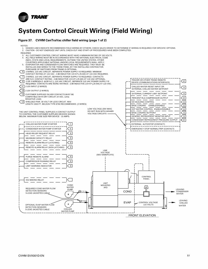
CVHM-SVX001D-EN 51
System Control Circuit Wiring (Field Wiring)Figure 37. CVHM CenTraVac chiller field wiring (page 1 of 2)
CONDENSER REFRIGERENT PRESSURE OUTPUT
10
10
9
8
10
8 PANELCONTROL
CHILLED WATER PUMP STARTER
CONDENSER WATER PUMP STARTER
CHILLEDWATER PUMP
PUMPWATERCOND
COND
6
7
115 VOLTSCONTROL VOLTAGEEVAP
ICE MAKING RELAY
8
8
8
8
8
8
8
PURGE REMOTE ALARM
MAXIMUM CAPACITY RELAY
REMOTE ALARM RELAY (LATCHING)
HEAD RELIEF REQUEST RELAY
LIMIT WARNING INDICATOR
COMPRESSOR RUNNING RELAY
REMOTE ALARM RELAY (NON-LATCHING)
5-LEAD JACKETED CABLEDETECTION SENSORSREQUIRED COND WATER FLOW
5-LEAD JACKETED CABLEDETECTION SENSORSOPTIONAL EVAP WATER FLOW
AFDMOUNTED
UNIT
FRONT ELEVATION
LEAVINGCONDENSERWATER
LEAVINGCHILLED
WATER
11
EMERGENCY STOP NORMAL/TRIP (CONTACT)
EXTERNAL AUTO/STOP (CONTACT)
BASE LOADING SETPOINT
GENERIC REFRIGERENT MONITOR INPUT
BASE LOADING ENABLE/DISABLE
HOT WATER CONTROL ENABLE/DISABLE
ICE BUILDING CONTROL
CONDENSER REFRIGERENT PRESSURE OUTPUT
PERCENT RLA COMPRESSOR OUTPUT
EXTERNAL CURRENT LIMIT SETPOINT
EXTERNAL CHILLED WATER SETPOINTCHILLED WATER RESET INPUT OR
TRACER OR OTHER TRANE REMOTEDEVICE (COMMUNICATIONS INTERFACE)
9
9
11
11
10
10
9
9
12
6
7
11
9
10
8
12
(SEE NAMEPLATE)VOLTAGE
LINE
ARE N.O. CONTACT RATING - 2.88 INDUCTIVE 1/3 H.P.(.25 kW) AT 115 VAC OPTIONAL.
2 WIRES, 115 VAC CIRCUIT, SEPARATE POWER SUPPLY IS REQUIRED. MINIMUMCONTACT RATING AT 115 VAC - 2.88 INDUCTIVE 1/3 H.P.(.25 kW) AT 115 VAC REQUIRED.2 WIRES, 115 VAC CIRCUIT, SEPARATE POWER SUPPLY IS REQUIRED. CONTACTS
2-10V OUTPUT
REQUIRED. CONTACTS ARE NO/NC RATINGS - 2.88 INDUCTIVE 1/3 H.P.(.25 kW) AT 115 VAC.2 OR 3 WIRES(N.O. &/OR N.C.), 115 VAC CIRCUIT, SEPARATE 115 VAC POWER SUPPLY IS
COMPATIBLE WITH DRY CIRCUIT 24 VDC, 12maCUSTOMER SUPPLIED SILVER CONTACTS MUST BE
2-10V INPUT
RESISTIVE LOAD.
2-10V OUTPUT (2 WIRES)
2-10V INPUT (2 WIRES)REQUIRED. CONTACTS ARE NO/NC RATINGS - 2.88 INDUCTIVE 1/3 H.P.(.25 kW) AT 115 VAC.2 OR 3 WIRES(N.O. &/OR N.C.), 115 VAC CIRCUIT, SEPARATE 115 VAC POWER SUPPLY IS
SHIELDED PAIR. 30 VOLT OR LESS CIRCUIT. MAXLENGTH 1500 FT. BELDON TYPE 8760 RECOMMENDED. (2 WIRES)
LOW VOLTAGE (30V MAX)DO NOT RUN WITH HIGHERVOLTAGE CIRCUITS
THE UNIT CONTROL PANEL SUPPLIES A CONTACT OUTPUT
BELOW. MAXIMUM FUSE SIZE PER DEVICE - 15 AMPS.TO CONTROL THE CUSTOMER SUPPLIED DEVICES SHOWN
ALL CUSTOMER CONTROL CIRCUIT WIRING MUST HAVE A MINIMUM RATING OF 150 VOLTS.
EVAPORATOR AND CONDENSER FLOW SWITCHES ARE REQUIRED. THEY MUST BEINSTALLED AND WIRED TO THE TRANE PANEL BY THE INSTALLING CONTRACTOR.
CAUTION - DO NOT ENERGIZE UNIT UNTIL CHECK-OUT AND START-UP PROCEDURES HAVE BEEN COMPLETED.DASHED LINES INDICATE RECOMMENDED FIELD WIRING BY OTHERS. CHECK SALES ORDER TO DETERMINE IF WIRING IS REQUIRED FOR SPECIFIC OPTIONS.
PURCHASE OF SWITCHES FROM TRANE IS OPTIONAL.
1.2.
REQUIRED
5.
3.
NOTES:
COUNTRIES APPLICABLE NATIONAL AND/OR LOCAL REQUIREMENTS SHALL APPLY.(NEC), STATE AND LOCAL REQUIREMENTS. OUTSIDE THE UNITED STATES, OTHERALL FIELD WIRING MUST BE IN ACCORDANCE WITH THE NATIONAL ELECTRICAL CODE4.
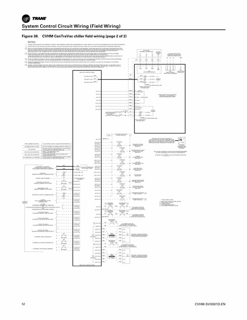
52 CVHM-SVX001D-EN
Figure 38. CVHM CenTraVac chiller field wiring (page 2 of 2)
1A6 J2-2
1A19 J2-2
1A19 J2-1
1A18 J2-4
1A18 J2-3
1A18 J2-2
1A18 J2-1
5S7
12
5S6
12
5S5
12
DEVICE PREFIX CODE
1 = MAIN UNIT CONTROL PANEL DEVICE2 = DRIVE PANEL DEVICE3 = PURGE DEVICE4 = UNIT MOUNTED DEVICE5 = CUSTOMER PROVIDED DEVICE
EXTERNAL ICE BUILDING COMMAND
EXTERNAL BASE LOADING E/D
1A17 J2-2
EXTERNAL HOT WATER CONTROL E/D
1A17 J2-3
1A17 J2-5
1A17 J2-6
2-10VDC OR 4-20mAEXTERNAL BASE LOADING SETPOINT
1A16 J2-2
1A16 J2-3
1A16 J2-5
2-10VDC OR 4-20mAGENERIC REFRIGERANT MONITOR INPUT
1A16 J2-6
2-10VDC OR 4-20mAEXTERNAL CURRENT LIMIT SETPOINT
1A15 J2-1
1A15 J2-3
1A15 J2-4
2-10VDC OR 4-20mAEXTERNAL CHILLED WATER SETPOINT
1A15 J2-6
2-10VDC
1A22 LINK + (5)
1A22 LINK - (6)
CONDENSER REFRIGERANT PRESSUREOR
EVAPORATOR/CONDENSER DIFFERENTIAL PRESSURE OUTPUTOR
CONDENSER HEAD PRESSURE CONTROL
CUSTOMER TO CONNECTETHERNET AND POWER CABLES
TO 4A2 ADAPTIVIEW DISPLAY MONITOR
OPTIONALMODBUS OR BACNET COMMUNICATION
BACNET OVER ETHERNET
EXTERNAL AUTO-STOP(REMOVE JUMPER 1W2 IF USED)
EMERGENCY STOP(REMOVE JUMPER 1W3 IF USED)
TRACER OR LONTALK COMMUNICATION
2-10VDC% RLA COMPRESSOR OUTPUT
(GENERIC BAS)
1A14 J2-1
1A14 J2-2
1A13 J2-4
1A13 J2-3
1A13 J2-2
1A13 J2-11W2
1W3
1A22ETHERNET
1A2-J3POWER
FACTORY CONNECTED
EN1
WB5 IN CONTROL PANEL
1X1-6
1A6 J3-2
1X1-5
1K27-21
1K27-20
1K27-19
1K26-21
1K26-20
1K26-19
1X1-5
1K26-4
1K26-17
1K26-18
1A5 J2-6
1A5 J2-4
1A5 J2-3
1A5 J2-1
5K1
1 2
5K2
1 2
REQUIRED
REQUIRED
EVAPORATOR WATERPUMP CONTROL
CONDENSER WATERPUMP CONTROL
1K27-18
1K27-17
1K27-4
1X1-6
WHT
BLU
BRN
BLK
GRY
WHT
BLU
BRN
BLK
GRY
WB11
2
3
CABLE1
4
5
4R17
WHT
BLU
OPTIONAL TRANE PROVIDEDPRIMARY EVAPORATOR WATER
FLOW DETECTION SENSOR
BRN
BLK
GRY
WHT
BLU
BRN
BLK
GRY
WB12
2
3
CABLE1
4
5
4R18
5S17
1 2
1
5S18
2
OPTIONAL TRANE PROVIDEDPRIMARY CONDENSER WATER
FLOW DETECTION SENSOR
SECONDARYOPTIONAL
SECONDARYOPTIONAL
CUSTOMER SUPPLIEDSECONDARY EVAPORATOR
WATER PROOF OF FLOW DEVICE
4
4
5S17
1 2
1
5S18
2
PRIMARY
CUSTOMER SUPPLIEDSECONDARY CONDENSER
WATER PROOF OF FLOW DEVICE
REQUIRED
PRIMARYREQUIRED
SECONDARYOPTIONAL
SECONDARYOPTIONAL
CUSTOMER SUPPLIEDEVAPORATOR WATER
PROOF OF FLOW DEVICES
5H4
1 2
5H10
1 2
1
5H11
2
CUSTOMER SUPPLIEDCONDENSER WATER
PROOF OF FLOW DEVICES
5H6
1 2
5H1
1 2
5H7
1 2
5H2
1 2
5H8
1 2
1A9 J2-9
1A9 J2-7PURGE
ALARM INDICATOR(DEFAULT)
1A9 J2-3
1A9 J2-1CHILLER MAXIMUM
CAPACITY INDICATOR(DEFAULT)
1A8 J2-9
1A8 J2-7CHILLER LATCHINGALARM INDICATOR
(DEFAULT)
1A8 J2-3
1A8 J2-1
1A5 J2-12
1A5 J2-10
CHILLER NON-LATCHINGALARM INDICATOR
(DEFAULT)
ICE BUILDINGINDICATOR
1A8 J2-12
1A8 J2-10CHILLER
RUNNING INDICATOR(DEFAULT)
1A8 J2-6
1A8 J2-4CHILLER LIMIT
MODE INDICATOR(DEFAULT)
1X1-G
1A9 J2-6
1A9 J2-4CHILLER HEAD RELIEFREQUEST INDICATOR
(DEFAULT)
GRN/YEL
NGND HCUSTOMER PROVIDED
120VAC 60HZ 15A
MAIN UNIT CONTROL PANEL
1OPTIONAL 5H15 CHILLER LIMIT MODE INDICATOR
2
ANY 1A8 OR 1A9 DEFAULT OUTPUT MAY BE REPROGRAMMEDTO THE ALTERNATE STATUS OUTPUT SHOWN BELOW
OPTIONALOUTDOOR AIRTEMPERATURE
SENSOR
4R13
2X1
MAIN UNIT CONTROL PANELDRIVE PANELGND BLOCK
2Q1LINE POTENTIAL
MAIN CIRCUIT BREAKER
SHIPPED WITH THE UNIT FOR FIELDINSTALLATION TO THE WB2 COMMUNICATION
LINK CABLE IN THE MAIN UNIT CONTROL PANEL.REFER TO THE UNIT INSTALLATION LITERATUREFOR INSTALLATION OPTIONS AT THE JOB SITE.
L1 L2 L3 GND
L1(1)
L2(3)
L3(5)
T3T2T1 CUSTOMER PROVIDEDINCOMING LINE VOLTAGE(SEE UNIT NAMEPLATE)
T1/U T2/V T3/W
WHT
4M1 MOTORTERMINAL CONNECTIONS
BLK
GRN
SHIELD
WB22
GRN
BLK
WHT
1A22 IMC-A (2)
1A22 IMC-A (3)
1A22 IMC-A (4)
SHIELD GROUNDEDTHIS END ONLY
1X1-G
1X1-2
5V
1X1-3
5U
60A OR 61A
60A
62A OR 63A
62A
5W
58A
5T
59A
PROVIDEDBY TRANE
PROVIDED
3
BY TRANE
3
OPTIONAL
OPTIONAL
OPTIONAL
OPTIONAL
OPTIONAL
OPTIONAL
OPTIONAL
61A
OPTIONAL
63A
4
4
3
3
5
5
OPTIONAL
OPTIONAL
OPTIONAL
OPTIONAL
OPTIONAL
OPTIONAL
3
4
5
6
OPTIONAL
6
6
OPTIONAL
MOTOR
GNDHOUSING
WIRE NUMBER OR DEVICE FIELD WIRING CIRCUIT SELECTION INFORMATION
INCOMING SUPPLY LEADS SEE UNIT NAMEPLATE MINIMUM CIRCUIT AMPACITY.
ALL REMAINING LLID TERMINALS
5S3, 5S4, 5S5, 5S6 AND 5S7
CONTACT RATING; 2.88A INDUCTIVE, 1/3 HP, 0.25kWAT 110-120VAC. 14 AWG MAX WIRE SIZE.
24VDC, 12mA RESISTIVE LOAD.14 AWG MAX WIRE SIZE.
5S11, 5S12, 5S17 AND 5S18 CIRCUIT PROTECTED AT 20A, 110-120VAC 1PH.14 AWG MAX WIRE SIZE.
5K1 AND 5K2
CLASS 2WIRING
1
5S11
2
5S12
1 2
5S3
12
CONTACT RATING; 2.88A INDUCTIVE, 1/3 HP, 0.25kWAT 110-120VAC. 14 AWG MAX WIRE SIZE.
5S4
12
OPTIONAL
OPTIONAL
OPTIONAL
OPTIONAL
OPTIONAL
OPTIONAL
OPTIONAL
OPTIONAL
OPTIONAL
1A10 ETHERNET 1OPTIONAL
OPTIONAL
OPTIONAL
OPTIONAL
OPTIONAL
OPTIONAL
OPTIONAL
OPTIONAL
OPTIONAL
PEGND
260U209A208A207A
DRIVEPANEL GND
2F29-2
2X6-1
2X6-2
2X5-1
2X5-2
2X5-3
DRIVE PANEL GND
1X1-1
260AU
250A
251J
254C
1X1-12 2X6-3260C
1X1-18 2T4-X1266A
1X1-19 2T4-X2267A
2A1AFD POWER MODULE
120VAC 60HZ
27VAC 60HZ
2X6-4
2X6-5
HIGH PRESSURECUTOUT SWITCH
IN PURGECONTROL PANEL
SHIELD
SHIELD GROUNDED
3D
4C
THIS END ONLY
DRIVE PANEL GND
CLASS 2WIRING
CLASS 2WIRING
3S1-1
3S1-2
3A SPLICED
4A
7
1.
2.
7
7
TRANE SUPPLIED UNIT MOUNTEDROCKWELL 755 POWERFLEX
ADAPTIVE FREQUENCY DRIVE
NOTES:DASHED LINES INDICATE FIELD WIRING BY OTHERS. WIRE NUMBERS SHOWN ARE RECOMMENDED BY TRANE. REFER TO THE UNIT TO DETERMINE WHICH OPTIONS ARE PRESENT.
DO NOT ROUTE LOW VOLTAGE (30V) WITH CONTROL VOLTAGE (120V) AND DO NOT POWER UNIT UNTIL CHECK OUT AND START UP PROCEDURES HAVE BEEN COMPLETED.
INSTALLATION OF PRIMARY EVAPORATOR AND CONDENSER WATER PROOF OF FLOW DEVICES ARE REQUIRED. THESE ARE INDICATED AS OPTIONAL TRANE INSTALLED 1K26 AND 1K27 WATER FLOW DETECTION CONTROLLERS WITH 4B4 AND 4B5 SENSORS PROVIDED FOR CUSTOMER INSTALLATION OR AS CUSTOMER SUPPLIED AND INSTALLED 5S11 AND 5S12 WATER PROOF OF FLOW DEVICES. A WATER PROOF OF FLOW DEVICE MAY BE A FLOW SWITCH, WATER FLOW DETECTION CONTROLLER OR DIFFERENTIAL PRESSURE SWITCH. ANY COMBINATION OF FLOW DETECTION CIRCUITS SHOWN MAY BE USED BETWEEN THE EVAPORATOR AND CONDENSER.
INSTALLATION OF CUSTOMER SUPPLIED SECONDARY EVAPORATOR AND CONDENSER WATER PROOF OF FLOW DEVICES ARE AT THE DISCRETION OF THE CUSTOMER.THESE ARE INDICATED AS 5S17 AND 5S18 AND MAY BE A WATER PUMP INTERLOCK, VALVE END SWITCH OR ANY OTHER PROOF OF FLOW DEVICE.TRANE RECOMMENDS INSTALLATION OF THE 5S17 SECONDARY EVAPORATOR WATER PROOF OF FLOW DEVICE WHEN THE LEAVING WATER TEMPERATURE IS EXPECTED TOBE 38F OR LESS AND THAT THE METHOD USED IS INDEPENDENT OF THE PRIMARY WATER PROOF OF FLOW DEVICE TO PROVIDE REDUNDANCY.
IF THE CUSTOMER CHOOSES TO INSTALL EITHER SECONDARY WATER PROOF OF FLOW DEVICE THEN THE CUSTOMER MUST REMOVE TRANE FACTORY WIRE 5W BETWEEN1X1-5 AND 1K26-4 AND INSTALL 5S17 AS SHOWN AND/OR WIRE 5T BETWEEN 1X1-6 AND 1K27-4 AND INSTALL 5S18 AS SHOWN.
TRANE RECOMMENDS WIRING THE 5K42 EVAPORATOR AND 5K43 CONDENSER WATER PUMP CONTROL RELAYS AS SHOWN TO ALLOW THE 1K15 MODULE TO CONTROLPROPER SEQUENCING.
NORMAL FACTORY WIRING THAT WILL NEED TO BE CONNECTED IN THE FIELD BY OTHERS WHEN THE DRIVE IS SHIPPED SEPARATE FROM THE UNIT. IN THE EVENT THAT A FACTORY MOUNTED DRIVE NEEDS TO BE REMOVED IN THE FIELD TO AID UNIT INSTALLATION, LABEL AND REMOVE INDICATED WIRING. DISCONNECT CONDUITS FROM THE DRIVE PANEL AND ROUTE THEM UP ON THE UNIT TO ALLOW CLEARANCE. REMOVE DRIVE PANEL ENCLOSURE AND ASSOCIATED BRACKETS.
SSyysstteemm CCoonnttrrooll CCiirrccuuiitt WWiirriinngg ((FFiieelldd WWiirriinngg))
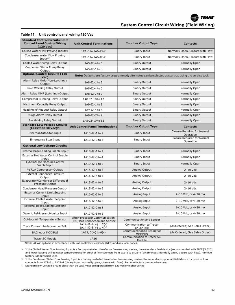
CVHM-SVX001D-EN 53
Table 11. Unit control panel wiring 120 Vac
Standard Control Circuits: UnitControl Panel Control Wiring
(120 Vac)Unit Control Terminations Input or Output Type Contacts
Chilled Water Flow Proving Input(a) 1X1-5 to 1A6-J3-2 Binary Input Normally Open, Closure with FlowCondenser Water Flow Proving
Input(b) 1X1-6 to 1A6-J2-2 Binary Input Normally Open, Closure with Flow
Chilled Water Pump Relay Output 1A5-J2-4 to 6 Binary Output Normally OpenCondenser Water Pump Relay
Output 1A5-J2-1 to 3 Binary Output Normally Open
Optional Control Circuits (120Vac) Note: Defaults are factory programmed; alternates can be selected at start-up using the service tool.
Alarm Relay MAR (Non-Latching)Output 1A8-J2-1 to 3 Binary Output Normally Open
Limit Warning Relay Output 1A8-J2-4 to 6 Binary Output Normally Open
Alarm Relay MMR (Latching) Output 1A8-J2-7 to 9 Binary Output Normally Open
Compressor Running Relay Output 1A8-J2-10 to 12 Binary Output Normally Open
Maximum Capacity Relay Output 1A9-J2-1 to 3 Binary Output Normally Open
Head Relief Request Relay Output 1A9-J2-4 to 6 Binary Output Normally Open
Purge Alarm Relay Output 1A9-J2-7 to 9 Binary Output Normally Open
Ice Making Relay Output 1A5-J2-10 to 12 Binary Output Normally OpenStandard Low Voltage Circuits
(Less than 30 Vac)(c) Unit Control Panel Terminations Input or Output Type Contacts
External Auto Stop Input 1A13-J2-1 to 2 Binary Input Closure Required for NormalOperation
Emergency Stop Input 1A13-J2-3 to 4 Binary Input Closure Required for NormalOperation
Optional Low Voltage Circuits
External Base Loading Enable Input 1A18-J2-1 to 2 Binary Input Normally OpenExternal Hot Water Control Enable
Input 1A18-J2-3 to 4 Binary Input Normally Open
External Ice Machine ControlEnable Input 1A19-J2-1 to 2 Binary Input Normally Open
% RLA Compressor Output 1A15-J2-1 to 3 Analog Output 2–10 VdcExternal Condenser Pressure
Output 1A15-J2-4 to 6 Analog Output 2–10 Vdc
Evaporator/Condenser DifferentialPressure Output 1A15-J2-4 to 6 Analog Output 2–10 Vdc
Condenser Head Pressure Control 1A15-J2-4 to 6 Analog Output 2–10 VdcExternal Current Limit Setpoint
Input 1A16-J2-2 to 3 Analog Input 2–10 Vdc, or 4–20 mA
External Chilled Water SetpointInput 1A16-J2-5 to 6 Analog Input 2–10 Vdc, or 4–20 mA
External Base Loading SetpointInput 1A17-J2-2 to 3 Analog Input 2–10 Vdc, or 4–20 mA
Generic Refrigerant Monitor Input 1A17-J2-5 to 6 Analog Input 2–10 Vdc, or 4–20 mA
Outdoor Air Temperature Sensor Inter-processor Communication(IPC) Bus Connection and Sensor Communication and Sensor
Trace Comm Interface or LonTalk1A14-J2-1(+) to 2(-)1A14-J2-3(+) to 4(-)
Communication to Traceror LonTalk
(As Ordered; See Sales Order)
BACnet or MODBUS 1A22, 5(+) to 6(-) Communication to BACnet orMODBUS
(As Ordered; See Sales Order)
Tracer SC Module 1A10 Communication to Tracer SCModule
Note: All wiring to be in accordance with National Electrical Code (NEC) and any local codes.
(a) If the Chilled Water Flow Proving Input is a factory-installed ifm efector flow-sensing device, the secondary field device (recommended with 38°F [3.3°C]and lower leaving chilled water temperatures) for proof of flow connects from 1X1-5 to 1K26-4 (binary input; normally open, closure with flow). Removefactory jumper when used.
(b) If the Condenser Water Flow Proving Input is a factory-installed ifm efector flow-sensing device, the secondary (optional) field device for proof of flowconnects from 1X1-6 to 1K27-4 (binary input; normally open, closure with flow). Remove factory jumper when used.
(c) Standard low-voltage circuits (less than 30 Vac) must be separated from 120 Vac or higher wiring.
SSyysstteemm CCoonnttrrooll CCiirrccuuiitt WWiirriinngg ((FFiieelldd WWiirriinngg))
54 CVHM-SVX001D-EN
Sensor CircuitsAll sensors are factory-installed except the optionaloutdoor air temperature sensor (refer to the followingfigure for sensor locations). This sensor is required forthe outdoor air temperature type of chilled water reset.
Use the following guidelines to locate and mount theoutdoor air temperature sensor. Mount the sensorprobe where needed; however, mount the sensormodule in the control panel.
SSyysstteemm CCoonnttrrooll CCiirrccuuiitt WWiirriinngg ((FFiieelldd WWiirriinngg))
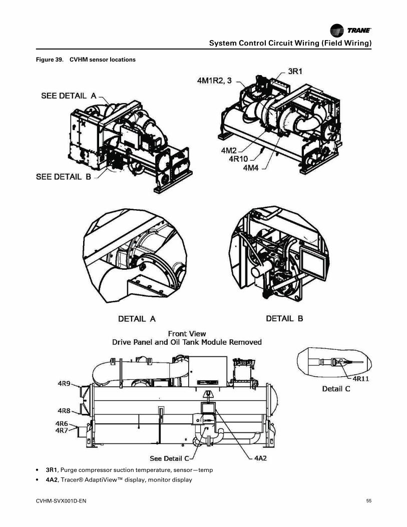
CVHM-SVX001D-EN 55
Figure 39. CVHM sensor locations
• 33RR11, Purge compressor suction temperature, sensor—temp
• 44AA22, Tracer® AdaptiView™ display, monitor display
SSyysstteemm CCoonnttrrooll CCiirrccuuiitt WWiirriinngg ((FFiieelldd WWiirriinngg))
56 CVHM-SVX001D-EN
• 44MM22, Inlet guide vane first-stage actuator, actuator
• 44MM44, Inlet guide vane second-stage actuator, actuator
• 44MM11RR22,,33, Motor winding temperature 1, 2, sensor—temp
• 44RR22, Outboard bearing temperature, sensor—temp
• 44RR33, Oil pump discharge pressure transducer, sensor—press transducer
• 44RR44, Oil pump tank pressure transducer, sensor—press transducer
• 44RR55, Oil pump temperature sensor, sensor—temp
• 44RR66, Evaporator, entering water temperature, sensor—temp
• 44RR77, Evaporator leaving water temperature, sensor—temp
• 44RR88, Condenser entering water temperature, sensor—temp
• 44RR99, Condenser leaving water temperature, sensor—temp
• 44RR1100, Evaporator saturated refrigerant temperature, sensor—temp
• 44RR1111, Condenser saturated refrigerant temperature, sensor—temp
CWR—Outdoor OptionThe outdoor temperature sensor is similar to the unit-mounted temperature sensors in that it consists of thesensor probe and the module. A four-wire inter-processor communication (IPC) bus is connected to themodule for 24 Vdc power and the communications link.Trane recommends mounting the sensor modulewithin the control panel and the sensor two wire leadsbe extended and routed to the outdoor temperaturesensor probe sensing location. This ensures the four-wire inter-processor control (IPC) bus protection andprovides access to the module for configuration atstart-up.
The sensor probe lead wire between the sensor probeand the module can be separated by cutting the two-wire probe lead leaving equal lengths of wire on eachdevice: the sensor probe and the sensor module.
NNoottee:: This sensor and module are matched and mustremain together or inaccuracy may occur.
These wires can then be spliced with two 14 to 18 AWG600V wires of sufficient length to reach the desiredoutdoor location with a maximum length 1000 ft(304.8 m). The module four-wire bus must beconnected to the control panel four-wire bus using theTrane-approved connectors provided.
The sensor will be configured (given its identity andbecome functional) at start-up when the Trane servicetechnician performs the start-up configuration. It willNOT be operational until that time.
NNoottee:: If shielded cable is used to extend the sensorleads, be sure to cover the shield wire with tapeat the junction box and ground it at the controlpanel. If the added length is run in conduit, doNOT run them in the same conduit with othercircuits carrying 30 or more volts.
IImmppoorrttaanntt:: Maintain at least 6 in. (15.24 cm) betweenlow-voltage (less than 30V) and highvoltage circuits. Failure to do so couldresult in electrical noise that may distort thesignals carried by the low-voltage wiring,including the IPC.
Optional Control and Output CircuitsInstall various optional wiring as required by theowner’s specifications (refer to “System Control CircuitWiring (Field Wiring),” p. 51).
Optional Tracer CommunicationInterfaceThis control option allows the control panel toexchange information—such as chiller status andoperating set points—with a Tracer® system.
NNoottee:: The circuit must be run in separate conduit toprevent electrical noise interference.
Additional information about the Tracer®communication interface option is published in theInstallation and Operationmanual that ships with theTracer® communication interface.
SSyysstteemm CCoonnttrrooll CCiirrccuuiitt WWiirriinngg ((FFiieelldd WWiirriinngg))
CVHM-SVX001D-EN 57
Controls SystemFigure 40. Controls system configuration diagram
Motor(PM)4M1
Evaporator(Shell and Tube)
Economizer
CompressorSuction
Oil
Separato
r
OiltoBearings
Condenser(Shell & Tube)
ExpansionOrifices
CondenserEnteringWaterTemp4R8
EvaporatorEnteringWater
Temperature4R6
EvaporatorLeavingWater
Temperature4R7
SaturatedCond RfgtTemperature
4R11
CondenserLeavingWaterTemp4R9
Sat EvapRfgt Temp
4R10
Outboard BearingTemp Sensor
(Optional)4R2
EvapDiff WaterPress(Optional)
CondDiff WaterPress(Optional)
CondenserRfgt
Pressure3R4
FirstStage IGV
4M2
Motor Winding Temps4M1R3 & 4M1R2
OilHeater4E1
OilTankPress4R4
Oil Temperature4R5
Wrap Around Pipe
Oil to Bearings
CprsrDischargeTemp
(Optional) 4R16
EvapWaterFlowSwitch4R17
CondWaterFlowSwitch4R18
HPCSwitch3S1
Vent to Evap PurgePurge CprsrSuction Temp
3R1
LiquidDrainLine
Vapor PickupLine
Control Panel (Standard):Power Supply 1 - 1A1Power Supply 2 - 1A2Motor Winding Temperatures 1 and 2 – 1A26 (TWT)External Auto/Stop and Emergency Stop – 1A13 (DB)Cond and Evap Water Pumps, Oil Tank Heater, and Ice Building Relays – 1A5 (QR)Cond and Evap Water Flow Switch - 1A6 (DHVB)Oil Pump Motor Relay - 1A7 (HPR)UC800 – 1A22TD12 – 4A2
Control Panel (Optional):External Current Limit and Chilled Water Setpoints – 1A16 (DA)External Ice Building Command – 1A19 (DB)Programmable Relays Module 1 – 1A8 (QR)Programmable Relays Module 2 – 1A9 (QR)% RLA and Cond Refrigerant Pressure Outputs – 1A15 (DA)Evaporator and Condenser Differential Water Pressure Inputs (DA)External Base Loading and Hot Water Control - 1A18 (DB) External Base Loading Setpoint and Refrigerant Monitor Input – 1A17 (DA)Vibration Input – 1A29 (DA)Comm 4 – 1A14Comm 5 LCI-C – 1A14Tracer SC Module – 1A10
Purge Liquid Level Switch - 3A4 (DB)Purge Pumpout, and Alarm Relay - 3A3 (QR)Purge Pumpout and Exhaust Solenoids - 3A1 (DT)Purge Condensing Unit Relay – 3A2 (HPR)
Control Panel
Purge Panel
Oil Eductor Line
Oil Return Line
Motor Cooling Refrigerant
CoolingRefrigerant
RfgtPumpSupply
UC800 IPC3+
-
MotorCoolingDrain
Outdoor Air TempSensor(Optional)
4R13
OilTankVent
L1 L3L2
U
AFD32A2
V W
OilS
eperato
rDrain
Regulator
Filter
Dryer
OilDischargePressure
4R3
Revision: DDate: 7/12/2016Author: Ryan Doud
OilTank
WW
Dryer
Oil/Rfgt Pump4M3
Eductor
Eductor
Filte
rAFDCoolingRfgt
SecondStage IGV
4M4
T1 T2 T3
OilR
eturn
Line
ToEvap
Oil Return Line
Oil ReturnLine
AFD CoolingOrifice
DriveCoolingBPHX
Glycol Pump
Schematic Wiring DrawingsPlease refer to the submittals and drawings thatshipped with the unit. Additional wiring drawings for
CenTraVac™ chillers are available from your localTrane office.
SSyysstteemm CCoonnttrrooll CCiirrccuuiitt WWiirriinngg ((FFiieelldd WWiirriinngg))
58 CVHM-SVX001D-EN
Operating PrinciplesGeneral RequirementsOperation and maintenance information for CVHMCenTraVac™ chillers are covered in this section. Bycarefully reviewing this information and following theinstructions given, the owner or operator cansuccessfully operate and maintain a CenTraVac™chiller. If mechanical problems do occur, however,contact a Trane service technician to ensure properdiagnosis and repair of the unit.
IImmppoorrttaanntt:: Although CenTraVac™ chillers can operatethrough surge, it is NOT recommended tooperate them through repeated surges overlong durations. If repeated surges of longdurations occur, contact your Trane ServiceAgency to resolve the issue.
Cooling CycleWhen in the cooling mode, liquid refrigerant isdistributed along the length of the evaporator andsprayed through small holes in a distributor (i.e.,running the entire length of the shell) to uniformly coateach evaporator tube. Here, the liquid refrigerantabsorbs enough heat from the system water circulatingthrough the evaporator tubes to vaporize. The gaseousrefrigerant is then drawn through the eliminators(which remove droplets of liquid refrigerant from thegas) and the first-stage variable inlet guide vanes, andinto the impeller.
CVHM CompressorCompressed gas from the first-stage impeller isdischarged through the wrap-around pipe to thesecond-stage variable guide vanes and into the second-stage impeller. Here, the refrigerant gas is againcompressed, and then discharged into the condenser.Baffles within the condenser shell distribute thecompressed refrigerant gas evenly across thecondenser tube bundle. Cooling tower water circulatedthrough the condenser tubes absorbs heat from therefrigerant, causing it to condense. The liquidrefrigerant then flows out of the bottom of thecondenser, passing through an orifice plate and intothe economizer.
The economizer reduces the energy requirements ofthe refrigerant cycle by eliminating the need to pass allgaseous refrigerant through both stages ofcompression (refer to the following figure). Notice thatsome of the liquid refrigerant flashes to a gas becauseof the pressure drop created by the orifice plate, thusfurther cooling the liquid refrigerant. This flash gas isthen drawn directly from the economizer into the
second-stage impellers of the compressor. Allremaining liquid refrigerant flows out of theeconomizer, passing through another orifice plate andinto the evaporator.
Figure 41. Pressure enthalpy curve
Condenser
Economizer
Evaporator
CompressorSecond Stage
CompressorFirst Stage
6
5 4
3
1 2
Pre
ssure
Enthalpy
P3
P1
P2
Figure 42. Refrigerant flow
Oil and Refrigerant PumpCompressor Lubrication SystemA schematic diagram of the compressor lubricationsystem is illustrated in the following figure. Oil ispumped from the oil tank (by a pump and motorlocated within the tank) through an oil pressureregulating valve designed to maintain a net oilpressure of 22 to 26 psid (151.7 to 179.3 kPaD). It is thenfiltered and sent to the compressor motor bearings.From the bearings, the oil drains back to the manifoldand separator under the motor and then on to the oiltank.
CVHM-SVX001D-EN 59
Figure 43. Oil refrigerant pumpFile
r
32
1
9
6
Compressor lubrication system
Motor cooling system
Oil reclaim system
Compressor
Oil
Sep
ara
tor
Condenser
Evaporator
Oil Tank
FirstStage
SecondStage
Oil
R
etu
rnLin
e
Mo
tor C
oo
ling
Dra
in
Motor Cooling Refrigerant
Oil to Bearings
Vent toEvaporator
Oil Return Line
Oil R
etu
rnLin
e t
oEvap
ora
tor
Mo
tor
Co
oli
ng
Refr
igera
nt
Oil t
o B
eari
ng
s
Oil
Tan
k V
en
t
Oil
Sep
ara
tor
Dra
in
Eductor
Oil Return Line
Oil Eductor Line
Fil
ter
Filter
Regulator
Oil/RefrigerantPump
Dryer
Refr
igera
nt
Pu
mp
Su
pp
ly
1
-
234
5
67
89
=
e
q
r
t
w
0
1. Motor coolant return to condenser
2. Oil tank vent to evaporator
3. Oil separator and tank vent manifold
4. Tank vent line
5. Condenser
6. High pressure condenser gas to drive oil reclaim eductors
7. Oil return to tank
8. Oil tank
9. Oil reclaim from evaporator (second eductor)
10. Liquid refrigerant to pump
11. Oil supply to bearings
12. Compressor
13. Liquid refrigerant motor coolant supply
14. Evaporator
15. Oil reclaim from first stage suction cover (first eductor)
16. Oil reclaim from second stage suction cover to evaporator
17. Motor coolant filter
OOppeerraattiinngg PPrriinncciipplleess
60 CVHM-SVX001D-EN
CCAAUUTTIIOONNHHoott SSuurrffaaccee!!FFaaiilluurree ttoo ffoollllooww iinnssttrruuccttiioonnss bbeellooww ccoouulldd rreessuulltt iinnmmooddeerraattee iinnjjuurryy..SSuurrffaaccee tteemmppeerraattuurreess ccaann rreeaacchh 115500°°FF ((6666°°CC)).. TTooaavvooiidd ppoossssiibbllee sskkiinn bbuurrnnss,, ssttaayy cclleeaarr ooff tthheesseessuurrffaacceess.. IIff ppoossssiibbllee,, aallllooww ssuurrffaacceess ttoo ccooooll bbeeffoorreesseerrvviicciinngg.. IIff sseerrvviicciinngg iiss nneecceessssaarryy wwhhiillee ssuurrffaacceetteemmppeerraattuurreess aarree ssttiillll eelleevvaatteedd,, yyoouu MMUUSSTT ppuutt oonnaallll PPeerrssoonnaall PPrrootteeccttiivvee EEqquuiippmmeenntt ((PPPPEE))..
To ensure proper lubrication and prevent refrigerantfrom condensing in the oil tank, a 750-watt heater is ina well in the oil tank. The heater is used to warm the oilwhile the unit is off. With the default settings, RunningOil Temperature Control is enabled, and the RunningOil Temperature Setpoint is factory-programmed at110°F (43.3°C). The heater energizes as needed tomaintain 140°F to 145°F (60.0°C to 62.8°C) when thechiller is not running.
When the chiller is operating, the temperature of the oiltank is typically 100°F to 160°F (37.8°C to 71.1°C). Theoil return lines from the bearings transport oil andsome seal leakage refrigerant. The oil return lines arerouted into a manifold and separator under the motor.Gas flow exits the top of the manifold and is vented tothe evaporator. Oil exits the bottom of the manifoldand returns to the tank. Separation of the seal leakagegas in the separator keeps this gas out of the tank.
An eductor system is used to reclaim oil from bothsuction covers and the evaporator, and deposit it backinto the oil tank. The first stage suction cover andevaporator eductor return to the oil tank; the secondstage suction cover eductor drains to the evaporator.The evaporator eductor line has a shut-off valvemounted by the evaporator. The shut-off valve will beset during commissioning, but may be adjusted laterby a qualified technician as necessary for oil return. Anormal operating setting for the valve may range fromfull closed to one turn open.
NNoottee:: Depending on operating conditions, the oilsump’s normal operating oil level may vary fromjust below the bottom sight glass to near the topof the upper sight glass.
Tracer AdaptiView DisplayInformation is tailored to operators, servicetechnicians, and owners.
When operating a chiller, there is specific informationyou need on a day-to-day basis—setpoints, limits,diagnostic information, and reports.
Day-to-day operational information is presented at thedisplay. Logically organized groups of information—chiller modes of operation, active diagnostics, settings,graphs, and reports put information conveniently atyour fingertips. For more information, refer to Tracer
AdaptiView Display for Water-cooled CenTraVacChillers Operations Guide (CTV-SVU01*-EN).
Adaptive Frequency DriveIntroductionThe refrigerant-cooled Adaptive Frequency™ drive(AFD) used with the CVHM CenTraVac™ chiller is apulse width modulated (PWM) design incorporating anInsulated Gate Bipolar Transistor (IGBT) inverter. Thisdrive converts AC power to DC power and back to ACpower. The incoming line volts are converted to about700 Vdc and are stored in a section of capacitors. TheDC output feeds the inverter IGBTs that switch atpredetermined time to change the DC input voltage to asymmetrical AC output voltage of desired magnitudeand frequency. The output frequency range is 0 to500 hertz.
A typical bus voltage for the AFD is 700 Vdc, which canrun in a dynamic range of 350 to 900 Vdc with a steadystate range of 480 to 780 Vdc.
A combination of two distinct operating modes makeup the AFD control within the chiller’s UC800 control:first, by controlling the inlet vanes, and second, bymodulating impeller speed. The IGBTs control thespeed in response to the UC800 compressor controlsignal. Circuit breakers, surge protectors, and groundfaults are standard on all AFD units.
Some of the basic principles of the drive are:
• Optional: Passive harmonic filtering to meet IEEE-519 recommended limits.
• Unit displacement power factor of 0.98 or better atfull load and a value of 0.96 at part load with totalharmonic distortion (THD) filter.
• Low inrush current.
• The current never exceeds the full load amps.
• The AFD varies the motor speed in response to thespeed command from the UC800 control.
The CenTraVac™ chiller control panel has full controlof the unit operation, including the start/stop functions.If you encounter a fault condition or an alarm on thedrive, the Tracer® AdaptiView™ display will indicate“alarm” and an “alarm message.”
UC800 Adaptive Frequency Drive Control
Achieving EfficiencyAdjustable speed impeller control is used to improveCenTraVac™ chiller efficiency at part-load while towerrelief is available. This occurs because the addition ofthe variable frequency drive gives the chiller control anextra degree of control freedom. The combination ofinlet guide vane position and variable speed createsthe possibility to control both chiller capacity andcompressor efficiency. By manipulating speed and inletguide vane position, it is possible to adjust the
OOppeerraattiinngg PPrriinncciipplleess
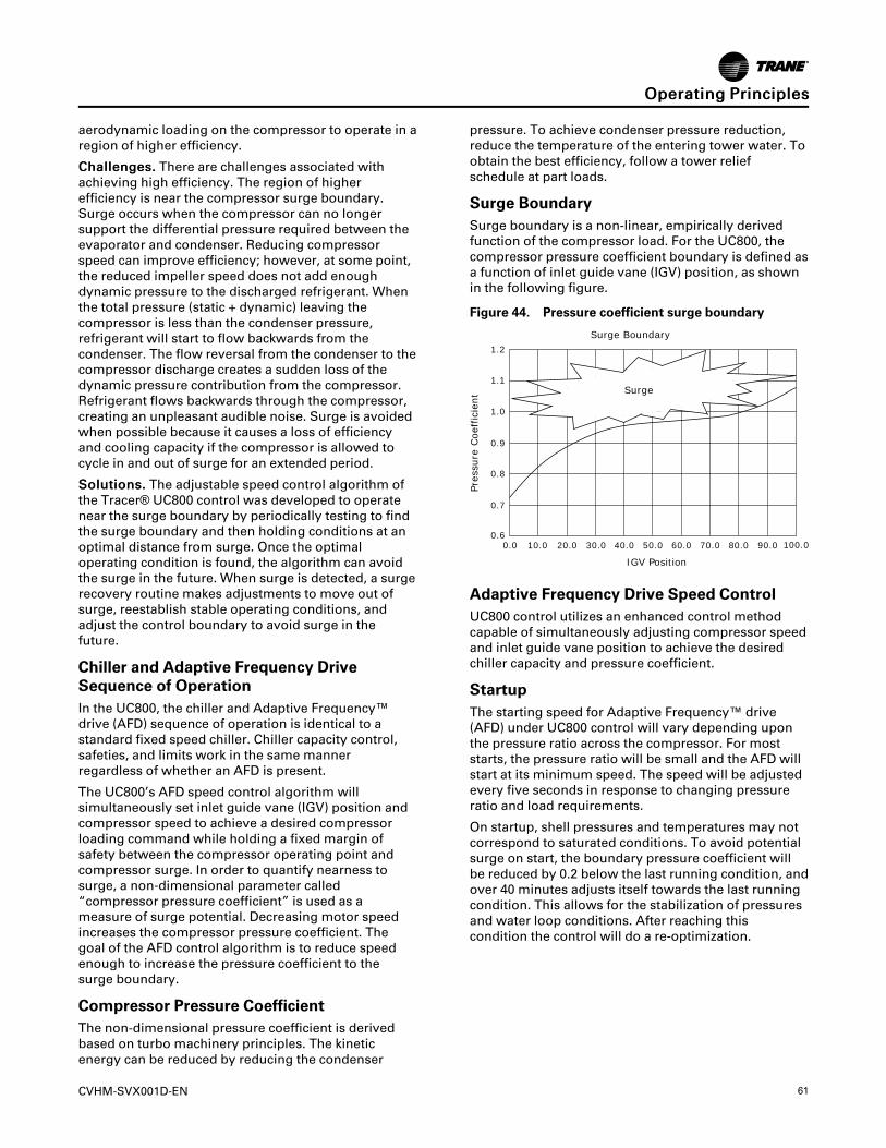
CVHM-SVX001D-EN 61
aerodynamic loading on the compressor to operate in aregion of higher efficiency.
CChhaalllleennggeess.. There are challenges associated withachieving high efficiency. The region of higherefficiency is near the compressor surge boundary.Surge occurs when the compressor can no longersupport the differential pressure required between theevaporator and condenser. Reducing compressorspeed can improve efficiency; however, at some point,the reduced impeller speed does not add enoughdynamic pressure to the discharged refrigerant. Whenthe total pressure (static + dynamic) leaving thecompressor is less than the condenser pressure,refrigerant will start to flow backwards from thecondenser. The flow reversal from the condenser to thecompressor discharge creates a sudden loss of thedynamic pressure contribution from the compressor.Refrigerant flows backwards through the compressor,creating an unpleasant audible noise. Surge is avoidedwhen possible because it causes a loss of efficiencyand cooling capacity if the compressor is allowed tocycle in and out of surge for an extended period.
SSoolluuttiioonnss.. The adjustable speed control algorithm ofthe Tracer® UC800 control was developed to operatenear the surge boundary by periodically testing to findthe surge boundary and then holding conditions at anoptimal distance from surge. Once the optimaloperating condition is found, the algorithm can avoidthe surge in the future. When surge is detected, a surgerecovery routine makes adjustments to move out ofsurge, reestablish stable operating conditions, andadjust the control boundary to avoid surge in thefuture.
Chiller and Adaptive Frequency DriveSequence of OperationIn the UC800, the chiller and Adaptive Frequency™drive (AFD) sequence of operation is identical to astandard fixed speed chiller. Chiller capacity control,safeties, and limits work in the same mannerregardless of whether an AFD is present.
The UC800’s AFD speed control algorithm willsimultaneously set inlet guide vane (IGV) position andcompressor speed to achieve a desired compressorloading command while holding a fixed margin ofsafety between the compressor operating point andcompressor surge. In order to quantify nearness tosurge, a non-dimensional parameter called“compressor pressure coefficient” is used as ameasure of surge potential. Decreasing motor speedincreases the compressor pressure coefficient. Thegoal of the AFD control algorithm is to reduce speedenough to increase the pressure coefficient to thesurge boundary.
Compressor Pressure CoefficientThe non-dimensional pressure coefficient is derivedbased on turbo machinery principles. The kineticenergy can be reduced by reducing the condenser
pressure. To achieve condenser pressure reduction,reduce the temperature of the entering tower water. Toobtain the best efficiency, follow a tower reliefschedule at part loads.
Surge BoundarySurge boundary is a non-linear, empirically derivedfunction of the compressor load. For the UC800, thecompressor pressure coefficient boundary is defined asa function of inlet guide vane (IGV) position, as shownin the following figure.
Figure 44. Pressure coefficient surge boundary
0.00.6
0.7
0.8
0.9
1.0
1.1
1.2
10.0 20.0 30.0 40.0 50.0 60.0 70.0 80.0 90.0 100.0
Surge
IGV Position
Surge Boundary
Pre
ssure
Coef
fici
ent
Adaptive Frequency Drive Speed ControlUC800 control utilizes an enhanced control methodcapable of simultaneously adjusting compressor speedand inlet guide vane position to achieve the desiredchiller capacity and pressure coefficient.
StartupThe starting speed for Adaptive Frequency™ drive(AFD) under UC800 control will vary depending uponthe pressure ratio across the compressor. For moststarts, the pressure ratio will be small and the AFD willstart at its minimum speed. The speed will be adjustedevery five seconds in response to changing pressureratio and load requirements.
On startup, shell pressures and temperatures may notcorrespond to saturated conditions. To avoid potentialsurge on start, the boundary pressure coefficient willbe reduced by 0.2 below the last running condition, andover 40 minutes adjusts itself towards the last runningcondition. This allows for the stabilization of pressuresand water loop conditions. After reaching thiscondition the control will do a re-optimization.
OOppeerraattiinngg PPrriinncciipplleess
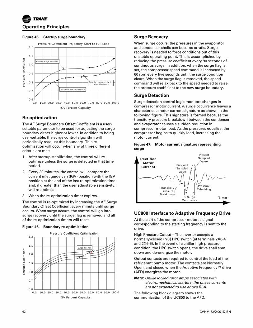
62 CVHM-SVX001D-EN
Figure 45. Startup surge boundary
0.00.6
0.7
0.8
0.9
1.0
1.1
1.2
10.0 20.0 30.0 40.0 50.0 60.0 70.0 80.0 90.0 100.0
IGV Percent Capacity
Pressure Coefficient Trajectory Start to Full Load
Pre
ssure
Coef
fici
ent
Full load
Running surge boundary
Surge boundary for startup
Boundary increases by 0.1 after 30 minutes
Re-optimizationThe AF Surge Boundary Offset Coefficient is a user-settable parameter to be used for adjusting the surgeboundary either higher or lower. In addition to beinguser-settable, the surge control algorithm willperiodically readjust this boundary. This re-optimization will occur when any of three differentcriteria are met:
1. After startup stabilization, the control will re-optimize unless the surge is detected in that timeperiod.
2. Every 30 minutes, the control will compare thecurrent inlet guide van (IGV) position with the IGVposition at the end of the last re-optimization timeand, if greater than the user adjustable sensitivity,will re-optimize.
3. When the re-optimization timer expires.
The control is re-optimized by increasing the AF SurgeBoundary Offset Coefficient every minute until surgeoccurs. When surge occurs, the control will go intosurge recovery until the surge flag is removed and allof the re-optimization timers will reset.
Figure 46. Boundary re-optimization
0.00.6
0.7
0.8
0.9
1.0
1.1
1.2
10.0 20.0 30.0 40.0 50.0 60.0 70.0 80.0 90.0 100.0
IGV Percent Capacity
Pressure Coefficient Optimization
Pre
ssure
Coef
fici
ent Surge detector
Surge RecoveryWhen surge occurs, the pressures in the evaporatorand condenser shells can become erratic. Surgerecovery is needed to force conditions out of thisunstable operating point. This is accomplished byreducing the pressure coefficient every 90 seconds ofcontinuous surge. In addition, when the surge flag isset, the compressor speed command is increased by60 rpm every five seconds until the surge conditionclears. When the surge flag is removed, the speedcommand will relax back to the speed needed to raisethe pressure coefficient to the new surge boundary.
Surge DetectionSurge detection control logic monitors changes incompressor motor current. A surge occurrence leaves acharacteristic motor current signature as shown in thefollowing figure. This signature is formed because thetransitory pressure breakdown between the condenserand evaporator causes a sudden reduction incompressor motor load. As the pressures equalize, thecompressor begins to quickly load, increasing themotor current.
Figure 47. Motor current signature representingsurge
Rectified Motor
Current
Time
Previous Sampled
Value
Present Sampled
Value
Transitory Pressure
Breakdown1 Surge
Occurrence
Pressure Rebuilding
UC800 Interface to Adaptive Frequency DriveAt the start of the compressor motor, a signalcorresponding to the starting frequency is sent to thedrive.
High Pressure Cutout—The inverter accepts anormally-closed (NC) HPC switch (at terminals 2X6-4and 2X6-5). In the event of a chiller high pressurecondition, the HPC switch opens, the drive shall shutdown and de-energize the motor.
Output contacts are required to control the load of therefrigerant pump motor. The contacts are NormallyOpen, and closed when the Adaptive Frequency™ drive(AFD) energizes the motor.
NNoottee:: Unlike locked rotor amps associated withelectromechanical starters, the phase currentsare not expected to rise above RLA.
The following block diagram shows thecommunication of the UC800 to the AFD.
OOppeerraattiinngg PPrriinncciipplleess
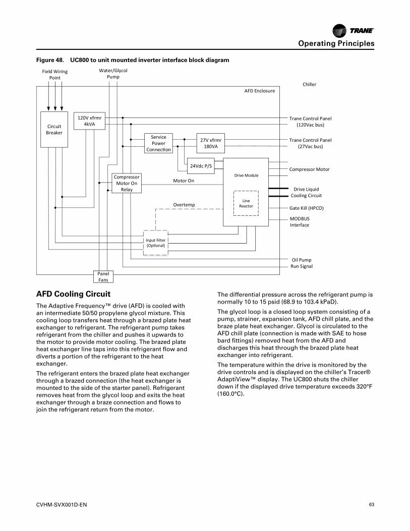
CVHM-SVX001D-EN 63
Figure 48. UC800 to unit mounted inverter interface block diagram
Drive Module
Line Reactor
Input Filter(Op!onal)
CircuitBreaker
120V xfrmr4kVA
Overtemp
ServicePower
Connec!on180VA
27V xfrmr
24Vdc P/S
Compressor Motor On
Relay
Panel Fans
Motor On
Oil Pump Run Signal
PointField Wiring Water/Glycol
Pump
Trane Control Panel(120Vac bus)
Trane Control Panel(27Vac bus)
Compressor Motor
Drive Liquid Cooling Circuit
Gate Kill (HPCO)
MODBUSInterface
AFD EnclosureChiller
AFD Cooling CircuitThe Adaptive Frequency™ drive (AFD) is cooled withan intermediate 50/50 propylene glycol mixture. Thiscooling loop transfers heat through a brazed plate heatexchanger to refrigerant. The refrigerant pump takesrefrigerant from the chiller and pushes it upwards tothe motor to provide motor cooling. The brazed plateheat exchanger line taps into this refrigerant flow anddiverts a portion of the refrigerant to the heatexchanger.
The refrigerant enters the brazed plate heat exchangerthrough a brazed connection (the heat exchanger ismounted to the side of the starter panel). Refrigerantremoves heat from the glycol loop and exits the heatexchanger through a braze connection and flows tojoin the refrigerant return from the motor.
The differential pressure across the refrigerant pump isnormally 10 to 15 psid (68.9 to 103.4 kPaD).
The glycol loop is a closed loop system consisting of apump, strainer, expansion tank, AFD chill plate, and thebraze plate heat exchanger. Glycol is circulated to theAFD chill plate (connection is made with SAE to hosebard fittings) removed heat from the AFD anddischarges this heat through the brazed plate heatexchanger into refrigerant.
The temperature within the drive is monitored by thedrive controls and is displayed on the chiller’s Tracer®AdaptiView™ display. The UC800 shuts the chillerdown if the displayed drive temperature exceeds 320°F(160.0°C).
OOppeerraattiinngg PPrriinncciipplleess
64 CVHM-SVX001D-EN
Figure 49. Schematic of the cooling circuit
Isolation Valve
Refrigerant Suction Line
Refrigerant Supply Line
Refrigerant Return Line
Compressor
Drive
PS
Pump Discharge Pressure
Condenser
Evaporator
Condenser Sump
Filter
PSPump
Pump Suction Pressure
Isolation ValvePress Relief
Oil Tank
OOppeerraattiinngg PPrriinncciipplleess
CVHM-SVX001D-EN 65
Start-up and Shut-downThis section provides basic information on chilleroperation for common events.
Sequence of OperationAdaptive control algorithms are used on CenTraVac™chillers. This section illustrates common controlsequences.
Software Operation Overview DiagramThe following figure is a diagram of the five possiblesoftware states. This diagram can be thought of as astate chart, with the arrows and arrow text, depictingthe transitions between states:
• The text in the circles is the internal softwaredesignations for each state.
• The first line of text in the circles is the visible toplevel operating modes that can be displayed inTracer® AdaptiView™.
• The shading of each software state circlecorresponds to the shading on the time lines thatshow the chiller’s state.
There are five generic states that the software can bein:
• Power Up
• Stopped
• Starting
• Running
• Stopping
Figure 50. Software operation overview
Confirm
ed
Shutdown
StoppedStopped
Run Inhibit
StoppingPreparing to Shut Down
Shutting Down
RunningRunning
Running—Limit
StartingAuto
Waiting to StartStarting Compressor
PowerUp
StartCommandDiagnostic
Reset
Fast Restart or Satisfied Setpoint
Stop Command or Diagnostic
Stop CommandDiagnosticStar
tCon
firmed
In the following diagrams:
• The time line indicates the upper level operatingmode, as it would be viewed in the Tracer®AdaptiView™.
• The shading color of the cylinder indicates thesoftware state.
• Text in parentheses indicates sub-mode text asviewed in the Tracer® AdaptiView™.
• Text above the time line cylinder is used to illustrateinputs to the UC800. This may include user input tothe Tracer® AdaptiView™ touch screen, controlinputs from sensors, or control inputs from ageneric BAS.
66 CVHM-SVX001D-EN
• Boxes indicate control actions such as turning onrelays, or moving the inlet guide vanes.
• Smaller cylinders under the main cylinder indicatediagnostic checks.
• Text outside a box or cylinder indicates time-basedfunctions.
• Solid double arrows indicate fixed timers.
• Dashed double arrows indicate variable timers.
Start-up Sequence of OperationLogic circuits within the various modules willdetermine the starting, running, and stoppingoperation of the chiller. When operation of the chiller isrequired, the chiller mode is set at “Auto.” Using
customer-supplied power, the chilled water pump relayis energized and chilled water flow must be verifiedwithin 4 minutes and 15 seconds. The UC800 decides tostart the chiller based on the differential to startsetpoint. With the differential to start criteria met, theUC800 then energizes condenser water pump relaywith customer-supplied power (refer to the followingfigure).
Based on the Restart Inhibit function and theDifferential to Start setpoint, the oil pump is energized.The oil pressure must be at least 12 psid (82.7 kPaD) for60 continuous seconds and condenser water flowverified within 4 minutes and 15 seconds for thecompressor start sequence to be initiated.
Figure 51. Sequence of operation: power up to starting
Last Chiller ModeWas Auto
Call for Cooling
PowerApplied
toControls
Auto Waiting to Start Waiting to Start StartingCompressor
UC800Boot Time(30 to 50 seconds)
Enforce Power UpStart Delay Timer(0 to 30 minutes)
Wait for Highest Motor WindingTemp to Fall Below 165°F (73.9°C)
Wait for Oil Temp to Rise AboveSat Evap + 30°F (16.7°C)
and 100°F (37.8°C)
Prelube (60 seconds)
Enforce Stop to Start Timer Using Values fromReal Time Clock (5 to 200 seconds; 30 is default)
Energize EvaporatorWater Pump Relay
Confirm Evaporator WaterFlow Within 4 min 15 sec(6 second Filter)
Overdrive IGV Closed
Energize CondenserWater Pump Relay
Energize Oil Pump Relay
Confirm Condenser Water FlowWithin 4 min 15 sec(6 second Filter)
Confirm 12 psid (82.7 kPaD)Oil PressureWithin 3 minutes
Check for High Vacuum Lockout
Now that the compressor motor is running, the inletguide vanes and Adaptive Frequency™ Drive (AFD) willmodulate to the chiller load variation to satisfy chilledwater setpoint. The chiller continues to run in itsappropriate mode of operation: Normal, Softload, LimitMode, and so on (refer to the following figure[running]).
If the chilled water temperature drops below the chilledwater setpoint by an amount set as the differential tostop setpoint, a normal chiller stop sequence isinitiated as follows:
1. The inlet guide vanes are driven closed (up to
50 seconds).
2. After the inlet guide vanes are closed, the stop relayand the condenser water pump relays open to turnoff. The oil pump motor will continue to run for30 seconds post-lube while the compressor coaststo a stop. The chilled water pump will continue torun while the UC800 monitors leaving chilled watertemperature, preparing for the next compressormotor start based on the differential to startsetpoint.
The following figure (satisfied setpoint) illustrates thissequence.
SSttaarrtt--uupp aanndd SShhuutt--ddoowwnn
CVHM-SVX001D-EN 67
Figure 52. Sequence of operation: running
StartingCompressor
ChillerIs
Running
StarterStatus Is“Running”
Limit Mode ExitLimit Mode
Chiller Is Running Chiller Is RunningChiller Is Running—Limit
Modulate IGV/AFD*for LWT Control
Modulate IGV/AFD*for LWT Control
Modulate IGV/AFD*for LWT Control
Enforce All Running Mode Diagnostics
*Note: AFD applies to CVH only.
Figure 53. Sequence of operation: satisfied setpoint
Satisfied Setpoint
Preparing Shutdown Shutting Down Shutting DownRunning Auto
Close IGV (0 to 50 seconds) Postlube(CVH: 3 minutes)(CVG: 1 minute)
De-Energize Oil Pump
Confirm No Oil Pressure*5 minutes After Oil Pump is De-EnergizedDe-Energize
Compressor
Confirm No Compressor CurrentsWithin 0 to 30 seconds
De-Energize CondenserWater Pump Relay
Command IGV Closed
Enforce All Running Mode Diagnostics
*Note: CVH: No oil pressure is less than 3 psid (20.7 kPaD) CVG: No oil pressure is opened Oil Differential Pressure Switch
If the STOP key is pressed on the operator interface, thechiller will follow the same stop sequence as describedearlier except the chilled water pump relay will alsoopen and stop the chilled water pump after the chilledwater pump delay timer has timed out aftercompressor shut down (refer to the following figure[normal shut-down to stopped and run inhibit]).
If the immediate stop is initiated, a panic stop occurswhich follows the same stop sequence as pressing theSTOP key once, except the inlet guide vanes are notsequence-closed and the compressor motor isimmediately turned off.
SSttaarrtt--uupp aanndd SShhuutt--ddoowwnn
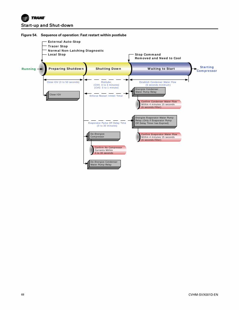
68 CVHM-SVX001D-EN
Figure 54. Sequence of operation: Fast restart within postlube
External Auto-Stop
Tracer StopNormal Non-Latching DiagnosticLocal Stop
Preparing Shutdown Shutting Down Waiting to Start
Stop CommandRemoved and Need to Cool
RunningStarting
Compressor
Close IGV (0 to 50 seconds) Postlube:(CVH: 0 to 3 minutes)(CVG: 0 to 1 minute)
Establish Condenser Water Flow (6 seconds minimum)
Enforce Restart Inhibit Timer
Evaporator Pump Off Delay Time(0 to 30 minutes)
Close IGV
Energize CondenserWater Pump Relay
Confirm Condenser Water FlowWithin 4 minutes 15 seconds(6 seconds Filter)
Energize Evaporator Water PumpRelay (Only if Evaporator Pump Off Delay Timer has Expired)
De-EnergizeCompressor
Confirm Evaporator Water FlowWithin 4 minutes 15 seconds(6 seconds Filter)
Confirm No CompressorCurrents Within0 to 30 seconds
De-Energize CondenserWater Pump Relay
SSttaarrtt--uupp aanndd SShhuutt--ddoowwnn
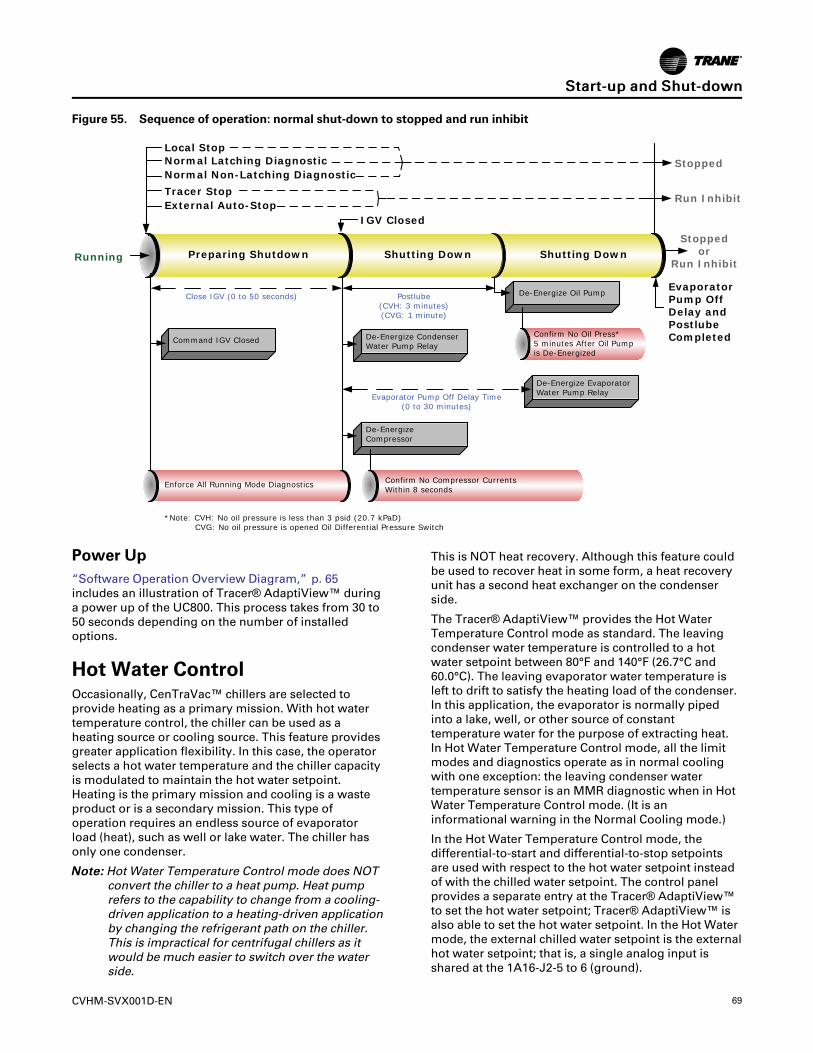
CVHM-SVX001D-EN 69
Figure 55. Sequence of operation: normal shut-down to stopped and run inhibit
Local StopNormal Latching DiagnosticNormal Non-Latching Diagnostic
Tracer StopExternal Auto-Stop
Preparing Shutdown Shutting Down Shutting Down
IGV Closed
Evaporator Pump Off Delay and PostlubeCompleted
Stopped
Run Inhibit
Stoppedor
Run InhibitRunning
Close IGV (0 to 50 seconds) Postlube(CVH: 3 minutes)(CVG: 1 minute)
Command IGV Closed
Enforce All Running Mode Diagnostics
De-Energize CondenserWater Pump Relay
De-EnergizeCompressor
De-Energize Oil Pump
De-Energize EvaporatorWater Pump RelayEvaporator Pump Off Delay Time
(0 to 30 minutes)
Confirm No Compressor CurrentsWithin 8 seconds
Confirm No Oil Press*5 minutes After Oil Pumpis De-Energized
*Note: CVH: No oil pressure is less than 3 psid (20.7 kPaD) CVG: No oil pressure is opened Oil Differential Pressure Switch
Power Up“Software Operation Overview Diagram,” p. 65includes an illustration of Tracer® AdaptiView™ duringa power up of the UC800. This process takes from 30 to50 seconds depending on the number of installedoptions.
Hot Water ControlOccasionally, CenTraVac™ chillers are selected toprovide heating as a primary mission. With hot watertemperature control, the chiller can be used as aheating source or cooling source. This feature providesgreater application flexibility. In this case, the operatorselects a hot water temperature and the chiller capacityis modulated to maintain the hot water setpoint.Heating is the primary mission and cooling is a wasteproduct or is a secondary mission. This type ofoperation requires an endless source of evaporatorload (heat), such as well or lake water. The chiller hasonly one condenser.
NNoottee:: Hot Water Temperature Control mode does NOTconvert the chiller to a heat pump. Heat pumprefers to the capability to change from a cooling-driven application to a heating-driven applicationby changing the refrigerant path on the chiller.This is impractical for centrifugal chillers as itwould be much easier to switch over the waterside.
This is NOT heat recovery. Although this feature couldbe used to recover heat in some form, a heat recoveryunit has a second heat exchanger on the condenserside.
The Tracer® AdaptiView™ provides the Hot WaterTemperature Control mode as standard. The leavingcondenser water temperature is controlled to a hotwater setpoint between 80°F and 140°F (26.7°C and60.0°C). The leaving evaporator water temperature isleft to drift to satisfy the heating load of the condenser.In this application, the evaporator is normally pipedinto a lake, well, or other source of constanttemperature water for the purpose of extracting heat.In Hot Water Temperature Control mode, all the limitmodes and diagnostics operate as in normal coolingwith one exception: the leaving condenser watertemperature sensor is an MMR diagnostic when in HotWater Temperature Control mode. (It is aninformational warning in the Normal Cooling mode.)
In the Hot Water Temperature Control mode, thedifferential-to-start and differential-to-stop setpointsare used with respect to the hot water setpoint insteadof with the chilled water setpoint. The control panelprovides a separate entry at the Tracer® AdaptiView™to set the hot water setpoint; Tracer® AdaptiView™ isalso able to set the hot water setpoint. In the Hot Watermode, the external chilled water setpoint is the externalhot water setpoint; that is, a single analog input isshared at the 1A16-J2-5 to 6 (ground).
SSttaarrtt--uupp aanndd SShhuutt--ddoowwnn
70 CVHM-SVX001D-EN
An external binary input to select external Hot WaterControl mode is on the EXOP OPTIONAL module 1A18terminals J2-3 to J2-4 (ground). Tracer® AdaptiView™also has a binary input to select chilled water control orhot water temperature control. There is no additionalleaving hot water temperature cutout; the HPC andcondenser limit provide for high temperature andpressure protection.
In Hot Water Temperature Control, the softloadingpulldown rate limit operates as a softloading pulluprate limit. The setpoint for setting the temperature ratelimit is the same setpoint for normal cooling as it is forhot water temperature control. The hot watertemperature control feature is not designed to run withice-making.
The factory set PID tuning values for the leaving watertemperature control are the same settings for bothnormal cooling and hot water temperature control.
Control Panel Devices and Unit-Mounted DevicesUnit Control PanelSafety and operating controls are housed in the unitcontrol panel, the starter panel, and the purge controlpanel. The control panel operator interface is calledTracer® AdaptiView™ and is located on an adjustablearm connected to the base of the control panel oralternate location. For more information aboutoperating Tracer® AdaptiView™, refer to TracerAdaptiView Display for Water-cooled CenTraVacChillers Operations Guide (CTV-SVU01*-EN).
The control panel houses several other controlsmodules called panel-mounted Low Level IntelligentDevices (LLIDs), power supply, terminal block, fuse,circuit breakers, and transformer. The inter-processorcommunication (IPC) bus allows the communicationsbetween LLIDs and the UC800. Unit-mounted devicesare called frame-mounted LLIDs and can betemperature sensors or pressure transducers. Theseand other functional switches provide analog andbinary inputs to the control system.
User-defined Language SupportTracer® AdaptiView™ is capable of displaying Englishtext or any of 26 other languages (27 total languages).Switching languages is simply accomplished from aLanguage Settings menu. The following languages areavailable:
• Arabic (Gulf Regions)
• Chinese—China
• Chinese—Taiwan
• Czech
• Dutch
• English
• French
• French (Canada)
• German
• Greek
• Hebrew
• Hungarian
• Indonesian
• Italian
• Japanese
• Korean
• Norwegian
• Polish
• Portuguese (Portugal)
• Portuguese (Brazil)
• Russian
• Romanian
• Spanish (Europe)
• Spanish (Latin America)
• Swedish
• Thai
• Turkish
Unit Start-up and Shut-downProcedures
WWAARRNNIINNGGLLiivvee EElleeccttrriiccaall CCoommppoonneennttss!!FFaaiilluurree ttoo ffoollllooww aallll eelleeccttrriiccaall ssaaffeettyy pprreeccaauuttiioonnsswwhheenn eexxppoosseedd ttoo lliivvee eelleeccttrriiccaall ccoommppoonneennttss ccoouullddrreessuulltt iinn ddeeaatthh oorr sseerriioouuss iinnjjuurryy..WWhheenn iitt iiss nneecceessssaarryy ttoo wwoorrkk wwiitthh lliivvee eelleeccttrriiccaallccoommppoonneennttss,, hhaavvee aa qquuaalliiffiieedd lliicceennsseedd eelleeccttrriicciiaannoorr ootthheerr iinnddiivviidduuaall wwhhoo hhaass bbeeeenn pprrooppeerrllyy ttrraaiinneeddiinn hhaannddlliinngg lliivvee eelleeccttrriiccaall ccoommppoonneennttss ppeerrffoorrmmtthheessee ttaasskkss..
SSttaarrtt--uupp aanndd SShhuutt--ddoowwnn
CVHM-SVX001D-EN 71
WWAARRNNIINNGGTTooxxiicc HHaazzaarrddss!!AA ssiiggnniiffiiccaanntt rreelleeaassee ooff rreeffrriiggeerraanntt iinnttoo aa ccoonnffiinneeddssppaaccee dduuee ttoo aa rruuppttuurree ddiisskk ffaaiilluurree ccoouulldd ddiissppllaacceeaavvaaiillaabbllee ooxxyyggeenn ttoo bbrreeaatthhee aanndd ccaauussee ppoossssiibblleeaasspphhyyxxiiaattiioonn.. FFaaiilluurree ttoo ffoollllooww iinnssttrruuccttiioonnss bbeelloowwccoouulldd rreessuulltt iinn ddeeaatthh oorr sseerriioouuss iinnjjuurryy..SShhoouulldd aa rruuppttuurree ddiisskk ffaaiill,, eevvaaccuuaattee tthhee aarreeaaiimmmmeeddiiaatteellyy aanndd ccoonnttaacctt tthhee aapppprroopprriiaattee rreessccuuee oorrrreessppoonnssee aauutthhoorriittyy..WWhhiillee tthhee uunniitt iiss ooffff,, ddoo nnoott aallllooww tthhee cchhiilllleerr ttooeexxcceeeedd 111100°°FF ((4433..33°°CC)) ffoorr mmooddeellss CCDDHHFF,, CCDDHHGG,,CCVVHHEE,, CCVVHHFF,, CCVVHHGG,, CCVVHHLL,, CCVVHHMM,, aanndd CCVVHHSS oorraabboovvee 113300°°FF ((5544..44°°CC)) ffoorr mmooddeellss CCDDHHHH aanndd CCVVHHHH..FFaaiilluurree ttoo pprreevveenntt hhiigghh cchhiilllleerr tteemmppeerraattuurree wwiillllccaauussee tthhee iinnssiiddee pprreessssuurree ttoo rriissee::•• DDoo nnoott rruunn eevvaappoorraattoorr wwaatteerr ppuummpp lloonnggeerr tthhaann3300 mmiinnuutteess aafftteerr tthhee cchhiilllleerr iiss sshhuutt ddoowwnn..•• EEnnssuurree tthhaatt tthhee eevvaappoorraattoorr iiss iissoollaatteedd ffrroomm tthheehhoott wwaatteerr lloooopp bbeeffoorree cchhaannggeeoovveerr ttoo hheeaattiinnggmmooddee..TThhee rruuppttuurree ddiisskk iiss ddeessiiggnneedd ttoo rreelliieevvee aannddddiisscchhaarrggee tthhee rreeffrriiggeerraanntt ffrroomm tthhee uunniitt iiff tthheepprreessssuurree iinn tthhee eevvaappoorraattoorr eexxcceeeeddss 1155 ppssiigg ((110033..44kkPPaaGG)) ffoorr mmooddeellss CCDDHHFF,, CCDDHHGG,, CCVVHHEE,, CCVVHHFF,,CCVVHHGG,, CCVVHHLL,, CCVVHHMM,, aanndd CCVVHHSS oorr 5500 ppssiigg ((334444..77kkPPaaGG)) ffoorr mmooddeellss CCDDHHHH aanndd CCVVHHHH..
Daily Unit Start-up1. Verify the chilled water pump and condenser water
pump starter are in ON or AUTO.
2. Verify the cooling tower is in ON or AUTO.
3. Check the oil tank oil level; the level must be visiblein or above the lower sight glass. Also, check the oiltank temperature; normal oil tank temperaturebefore start-up is 140°F to 145°F (60.0°C to 62.8°C).
NNoottee:: The oil heater is energized during thecompressor off cycle. During unit operation,the oil tank heater may be de-energized.
4. Check the chilled water setpoint and readjust it, ifnecessary, in the Chiller Settings menu.
5. If necessary, readjust the current limit setpoint inthe Chiller Setpoints menu.
6. Press AUTO.
The control panel also checks compressor motorwinding temperature and a start is initiated after aminimum restart inhibit time if the windingtemperature is less than 265°F (129.4°C). The chilledwater pump relay is energized and evaporator waterflow is proven. Next, the control panel checks theleaving evaporator water temperature and compares itto the chilled water setpoint. If the difference betweenthese values is less than the start differential setpoint,cooling is not needed.
If the control panel determines that the difference
between the evaporator leaving water temperature andchilled water setpoint exceeds the start differentialsetpoint, the unit enters the initiate Start Mode and theoil pump and the condenser water pump are started. Ifflow is not initially established within 4 minutes15 seconds of the condenser pump relay energization,an automatically resetting diagnostic “CondenserWater Flow Overdue” shall be generated, whichterminates the prestart mode and de-energizes thecondenser water pump relay. This diagnostic isautomatically reset if flow is established at any latertime.
NNoottee:: This diagnostic does NOT automatically reset ifTracer® AdaptiView™ is in control of thecondenser pump through its condenser pumprelay, since it is commanded off at the time ofthe diagnostic. It may reset and allow normalchiller operation if the pump was controlled fromsome external source.
When less than 5 seconds remain on the restart inhibit,the pre-start starter test is conducted on wye-deltastarters. If the compressor motor starts and acceleratessuccessfully, Running appears on the display. If thepurge is set to AUTO, the purge will start running andwill run as long as the chiller is running.
NNoottee:: If a manual reset diagnostic condition is detectedduring start-up, unit operation will be locked outand a manual reset is required before the start-up sequence can begin again. If the faultcondition has not cleared, the control panel willnot permit restart.
When the cooling requirement is satisfied, the controlpanel originates a Shutting down signal. The inletguide vanes are driven closed for 50 seconds, thecompressor stops, and the unit enters a 180-secondpost-lube period. The evaporator pump may continueto run for the amount of time set using Tracer®AdaptiView™.
After the post-lube cycle is done, the unit returns toauto mode.
Seasonal Unit Start-up1. Close all drain valves and reinstall the drain plugs in
the evaporator and condenser headers.
2. Service the auxiliary equipment according to thestart-up and maintenance instructions provided bythe respective equipment manufacturers.
3. Fill and vent the cooling tower, if used, as well asthe condenser and piping. At this point, all air mustbe removed from the system (including each pass).Then, close the vents in the condenser waterboxes.
4. Open all of the valves in the evaporator chilledwater circuit.
5. If the evaporator was previously drained, fill andvent the evaporator and chilled water circuit. Afterall air is removed from the system (including each
SSttaarrtt--uupp aanndd SShhuutt--ddoowwnn
72 CVHM-SVX001D-EN
pass), close the vent valves in the evaporatorwaterboxes.
6. Lubricate the external vane control linkage asneeded.
7. Check the adjustment and operation of each safetyand operating control.
8. Close all disconnect switches.
9. Perform instructions listed in “Daily Unit Start-up,” p. 71.
Daily Unit Shut-downNNoottee:: Also refer to the figure (satisfied setpoint) in
“Start-up Sequence of Operation,” p. 66.
1. Press STOP.
2. After compressor and water pumps shut down, theoperator may turn Pump Contactors to OFF or openpump disconnects.
Seasonal Unit Shut-downIImmppoorrttaanntt:: Control power disconnect switch must
remain closed to allow oil sump heateroperation. Failure to do this will allowrefrigerant to condense in the oil pump.
1. Open all disconnect switches except the controlpower disconnect switch.
2. Drain the condenser piping and cooling tower, ifused. Rinse with clean water.
3. Remove the drain and vent plugs from thecondenser headers to drain the condenser. Air-drybundle of residual water.
4. Once the unit is secured for the season, themaintenance procedures described in “NormalOperation,” p. 73 (tables for recommendedmaintenance of standard and optional features)should be performed by qualified Trane servicetechnicians.
NNoottee:: During extended shut-down periods, be sure tooperate the purge unit for a two-hour periodevery two weeks. This will prevent theaccumulation of air and non-condensables in themachine. To start the purge, change the purgemode to ON in the unit control “Settings Purge”menu. Remember to turn the purge mode to“Adaptive” after the two-hour run time.
SSttaarrtt--uupp aanndd SShhuutt--ddoowwnn
CVHM-SVX001D-EN 73
Recommended MaintenanceWWAARRNNIINNGG
HHaazzaarrddoouuss VVoollttaaggee ww//CCaappaacciittoorrss!!FFaaiilluurree ttoo ddiissccoonnnneecctt ppoowweerr aanndd ddiisscchhaarrggeeccaappaacciittoorrss bbeeffoorree sseerrvviicciinngg ccoouulldd rreessuulltt iinn ddeeaatthh oorrsseerriioouuss iinnjjuurryy..DDiissccoonnnneecctt aallll eelleeccttrriicc ppoowweerr,, iinncclluuddiinngg rreemmootteeddiissccoonnnneeccttss aanndd ddiisscchhaarrggee aallll mmoottoorr ssttaarrtt//rruunnccaappaacciittoorrss bbeeffoorree sseerrvviicciinngg.. FFoollllooww pprrooppeerrlloocckkoouutt//ttaaggoouutt pprroocceedduurreess ttoo eennssuurree tthhee ppoowweerrccaannnnoott bbee iinnaaddvveerrtteennttllyy eenneerrggiizzeedd.. FFoorr vvaarriiaabblleeffrreeqquueennccyy ddrriivveess oorr ootthheerr eenneerrggyy ssttoorriinnggccoommppoonneennttss pprroovviiddeedd bbyy TTrraannee oorr ootthheerrss,, rreeffeerr ttootthhee aapppprroopprriiaattee mmaannuuffaaccttuurreerr’’ss lliitteerraattuurree ffoorraalllloowwaabbllee wwaaiittiinngg ppeerriiooddss ffoorr ddiisscchhaarrggee ooffccaappaacciittoorrss.. VVeerriiffyy wwiitthh aa CCAATT IIIIII oorr IIVV vvoollttmmeetteerrrraatteedd ppeerr NNFFPPAA 7700EE tthhaatt aallll ccaappaacciittoorrss hhaavveeddiisscchhaarrggeedd..FFoorr aaddddiittiioonnaall iinnffoorrmmaattiioonn rreeggaarrddiinngg tthhee ssaaffeeddiisscchhaarrggee ooff ccaappaacciittoorrss,, sseeee PPRROODD--SSVVBB0066**--EENN..
NNOOTTIICCEECChheecckk PPuurrggee RRuunn--TTiimmee ffoorr UUnniittHHeerrmmeettiicc IInntteeggrriittyy!!FFaaiilluurree ttoo ffoollllooww iinnssttrruuccttiioonnss bbeellooww ccoouulldd rreessuulltt iinncchhiilllleerr ddaammaaggee..IIff ffrreeqquueenntt ppuurrggiinngg iiss rreeqquuiirreedd,, mmoonniittoorr ppuurrggeeppuummppoouutt rraattee,, aanndd iiddeennttiiffyy aanndd ccoorrrreecctt ssoouurrccee ooffaaiirr oorr wwaatteerr lleeaakk aass ssoooonn aass ppoossssiibbllee ttoo pprreevveennttmmooiissttuurree ccoonnttaammiinnaattiioonn ccaauusseedd bbyy lleeaakkaaggee..
NNOOTTIICCEEDDoo NNoott UUssee NNoonn--CCoommppaattiibbllee PPaarrttss oorrMMaatteerriiaallss!!UUssee ooff nnoonn--ccoommppaattiibbllee ppaarrttss oorr mmaatteerriiaallss ccoouullddrreessuulltt iinn eeqquuiippmmeenntt ddaammaaggee..OOnnllyy ggeennuuiinnee TTrraannee®® rreeppllaacceemmeenntt ccoommppoonneennttsswwiitthh iiddeennttiiccaall TTrraannee ppaarrtt nnuummbbeerrss sshhoouulldd bbee uusseeddiinn TTrraannee CCeennTTrraaVVaacc cchhiilllleerrss.. TTrraannee aassssuummeess nnoorreessppoonnssiibbiilliittyy ffoorr ddaammaaggeess rreessuullttiinngg ffrroomm tthhee uusseeooff nnoonn--ccoommppaattiibbllee ppaarrttss oorr mmaatteerriiaallss..
This section describes the basic chiller preventivemaintenance procedures, and recommends theintervals at which these procedures should beperformed. Use of a periodic maintenance program isimportant to ensure the best possible performance andefficiency from a CenTraVac™ chiller.
Recommended purge maintenance procedures aredetailed in Operation and Maintenance Guide: PurgeSystem with Tracer AdaptiView Control for Water-Cooled CenTraVac Chillers with R-514A Refrigerant(PRGG-SVX001*-EN).
Record Keeping FormsAn important aspect of the chiller maintenanceprogram is the regular completion of records. Refer to“Appendix A: Forms and Check Sheets,” p. 88 forcopies of the recommended forms. When filled outaccurately by the machine operator, the completedlogs can be reviewed to identify any developing trendsin the chiller’s operating conditions. For example, if themachine operator notices a gradual increase incondensing pressure during a month’s time, she cansystematically check and then correct the possiblecause of this condition.
Normal OperationTable 12. Normal operation
Operating Characteristic Normal ReadingApproximate EvaporatorPressure
6 to 9 psia (41.4 to 62.1 kPaA) /-9 to -6 psig (-62.1 to -41.4 kPaG)
Approximate CondenserPressure(a) , (b)
17 to 27 psia (117.2 to 182.2 kPaA) /2 to 12 psig (13.8 to 82.7 kPaG)(standard condenser)
Oil Sump TemperatureUnit not running 140°F to 176°F (60.0°C to 80.0°C)
Oil Sump TemperatureUnit running 95°F to 162°F (35.0°C to 72.2°C)
Oil Sump DifferentialOil Pressure(c) 22 to 26 psid (151.7 to 179.3 kPaD)
(a) Condenser pressure is dependent on condenser water temperature,and should equal the saturation pressure of the refrigerant at atemperature above that of leaving condenser water at full load.
(b) Normal pressure readings for ASME condenser exceed 12 psig(82.7 kPaG).
Table 12. Normal operation (continued)(c) Oil tank pressure: -9 to -6 psig (-62.1 to -41.4 kPaG). Discharge oil
pressure: 7 to 15 psig (48.3 to 103.4 kPaG).
NNOOTTIICCEEEEqquuiippmmeenntt DDaammaaggee!!FFaaiilluurree ttoo rreemmoovvee tthhee ssttrraaiinn rreelliieeff wwiitthh tthhee sseennssoorrccoouulldd rreessuulltt iinn eeqquuiippmmeenntt ddaammaaggee..DDoo NNOOTT aatttteemmpptt ttoo ppuullll sseennssoorr bbuullbb tthhrroouugghh tthheessttrraaiinn rreelliieeff;; aallwwaayyss rreemmoovvee tthhee eennttiirree ssttrraaiinn rreelliieeffwwiitthh tthhee sseennssoorr..
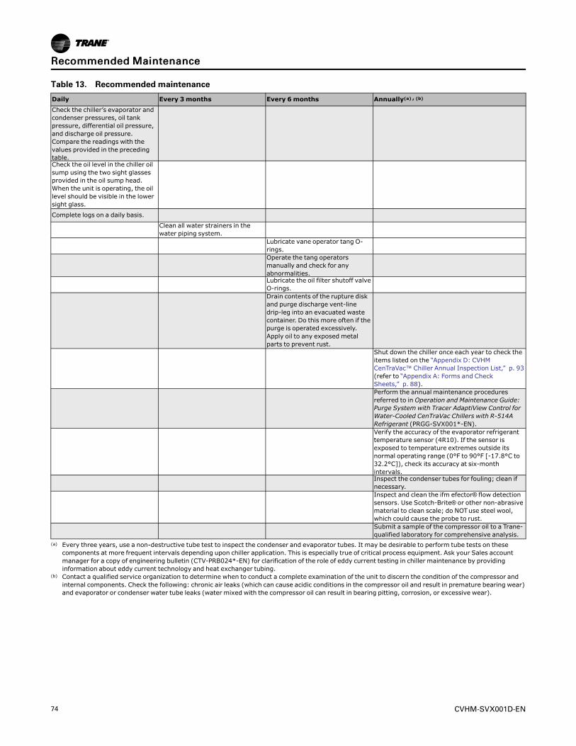
74 CVHM-SVX001D-EN
Table 13. Recommended maintenance
Daily Every 3months Every 6months Annually(a) , (b)
Check the chiller’s evaporator andcondenser pressures, oil tankpressure, differential oil pressure,and discharge oil pressure.Compare the readings with thevalues provided in the precedingtable.Check the oil level in the chiller oilsump using the two sight glassesprovided in the oil sump head.When the unit is operating, the oillevel should be visible in the lowersight glass.
Complete logs on a daily basis.
Clean all water strainers in thewater piping system.
Lubricate vane operator tang O-rings.Operate the tang operatorsmanually and check for anyabnormalities.Lubricate the oil filter shutoff valveO-rings.Drain contents of the rupture diskand purge discharge vent-linedrip-leg into an evacuated wastecontainer. Do this more often if thepurge is operated excessively.Apply oil to any exposed metalparts to prevent rust.
Shut down the chiller once each year to check theitems listed on the “Appendix D: CVHMCenTraVac™ Chiller Annual Inspection List,” p. 93(refer to “Appendix A: Forms and CheckSheets,” p. 88).Perform the annual maintenance proceduresreferred to in Operation and Maintenance Guide:Purge System with Tracer AdaptiView Control forWater-Cooled CenTraVac Chillers with R-514ARefrigerant (PRGG-SVX001*-EN).Verify the accuracy of the evaporator refrigeranttemperature sensor (4R10). If the sensor isexposed to temperature extremes outside itsnormal operating range (0°F to 90°F [-17.8°C to32.2°C]), check its accuracy at six-monthintervals.Inspect the condenser tubes for fouling; clean ifnecessary.Inspect and clean the ifm efector® flow detectionsensors. Use Scotch-Brite® or other non-abrasivematerial to clean scale; do NOTuse steel wool,which could cause the probe to rust.Submit a sample of the compressor oil to a Trane-qualified laboratory for comprehensive analysis.
(a) Every three years, use a non-destructive tube test to inspect the condenser and evaporator tubes. It may be desirable to perform tube tests on thesecomponents at more frequent intervals depending upon chiller application. This is especially true of critical process equipment. Ask your Sales accountmanager for a copy of engineering bulletin (CTV-PRB024*-EN) for clarification of the role of eddy current testing in chiller maintenance by providinginformation about eddy current technology and heat exchanger tubing.
(b) Contact a qualified service organization to determine when to conduct a complete examination of the unit to discern the condition of the compressor andinternal components. Check the following: chronic air leaks (which can cause acidic conditions in the compressor oil and result in premature bearing wear)and evaporator or condenser water tube leaks (water mixed with the compressor oil can result in bearing pitting, corrosion, or excessive wear).
RReeccoommmmeennddeedd MMaaiinntteennaannccee
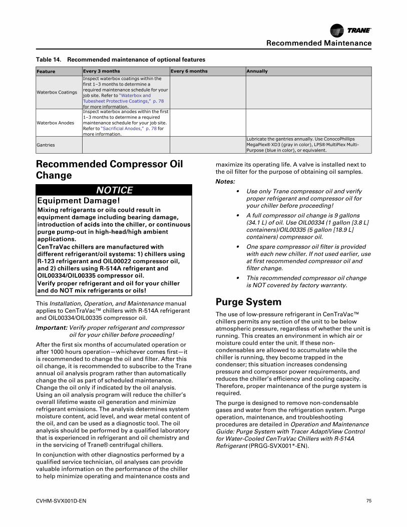
CVHM-SVX001D-EN 75
Table 14. Recommended maintenance of optional features
Feature Every 3months Every 6months Annually
Waterbox Coatings
Inspect waterbox coatings within thefirst 1–3 months to determine arequired maintenance schedule for yourjob site. Refer to “Waterbox andTubesheet Protective Coatings,” p. 78for more information.
Waterbox Anodes
Inspect waterbox anodes within the first1–3 months to determine a requiredmaintenance schedule for your job site.Refer to “Sacrificial Anodes,” p. 78 formore information.
GantriesLubricate the gantries annually. Use ConocoPhillipsMegaPlex® XD3 (gray in color), LPS®MultiPlex Multi-Purpose (blue in color), or equivalent.
Recommended Compressor OilChange
NNOOTTIICCEEEEqquuiippmmeenntt DDaammaaggee!!MMiixxiinngg rreeffrriiggeerraannttss oorr ooiillss ccoouulldd rreessuulltt iinneeqquuiippmmeenntt ddaammaaggee iinncclluuddiinngg bbeeaarriinngg ddaammaaggee,,iinnttrroodduuccttiioonn ooff aacciiddss iinnttoo tthhee cchhiilllleerr,, oorr ccoonnttiinnuuoouussppuurrggee ppuummpp--oouutt iinn hhiigghh--hheeaadd//hhiigghh aammbbiieennttaapppplliiccaattiioonnss..CCeennTTrraaVVaacc cchhiilllleerrss aarree mmaannuuffaaccttuurreedd wwiitthhddiiffffeerreenntt rreeffrriiggeerraanntt//ooiill ssyysstteemmss:: 11)) cchhiilllleerrss uussiinnggRR--112233 rreeffrriiggeerraanntt aanndd OOIILL0000002222 ccoommpprreessssoorr ooiill,,aanndd 22)) cchhiilllleerrss uussiinngg RR--551144AA rreeffrriiggeerraanntt aannddOOIILL0000333344//OOIILL0000333355 ccoommpprreessssoorr ooiill..VVeerriiffyy pprrooppeerr rreeffrriiggeerraanntt aanndd ooiill ffoorr yyoouurr cchhiilllleerraanndd ddoo NNOOTT mmiixx rreeffrriiggeerraannttss oorr ooiillss!!
This Installation, Operation, and Maintenancemanualapplies to CenTraVac™ chillers with R-514A refrigerantand OIL00334/OIL00335 compressor oil.
IImmppoorrttaanntt:: Verify proper refrigerant and compressoroil for your chiller before proceeding!
After the first six months of accumulated operation orafter 1000 hours operation—whichever comes first—itis recommended to change the oil and filter. After thisoil change, it is recommended to subscribe to the Traneannual oil analysis program rather than automaticallychange the oil as part of scheduled maintenance.Change the oil only if indicated by the oil analysis.Using an oil analysis program will reduce the chiller’soverall lifetime waste oil generation and minimizerefrigerant emissions. The analysis determines systemmoisture content, acid level, and wear metal content ofthe oil, and can be used as a diagnostic tool. The oilanalysis should be performed by a qualified laboratorythat is experienced in refrigerant and oil chemistry andin the servicing of Trane® centrifugal chillers.
In conjunction with other diagnostics performed by aqualified service technician, oil analyses can providevaluable information on the performance of the chillerto help minimize operating and maintenance costs and
maximize its operating life. A valve is installed next tothe oil filter for the purpose of obtaining oil samples.
NNootteess::
• Use only Trane compressor oil and verifyproper refrigerant and compressor oil foryour chiller before proceeding!
• A full compressor oil change is 9 gallons(34.1 L) of oil. Use OIL00334 (1 gallon [3.8 L]containers)/OIL00335 (5 gallon [18.9 L]containers) compressor oil.
• One spare compressor oil filter is providedwith each new chiller. If not used earlier, useat first recommended compressor oil andfilter change.
• This recommended compressor oil changeis NOT covered by factory warranty.
Purge SystemThe use of low-pressure refrigerant in CenTraVac™chillers permits any section of the unit to be belowatmospheric pressure, regardless of whether the unit isrunning. This creates an environment in which air ormoisture could enter the unit. If these non-condensables are allowed to accumulate while thechiller is running, they become trapped in thecondenser; this situation increases condensingpressure and compressor power requirements, andreduces the chiller’s efficiency and cooling capacity.Therefore, proper maintenance of the purge system isrequired.
The purge is designed to remove non-condensablegases and water from the refrigeration system. Purgeoperation, maintenance, and troubleshootingprocedures are detailed in Operation and MaintenanceGuide: Purge System with Tracer AdaptiView Controlfor Water-Cooled CenTraVac Chillers with R-514ARefrigerant (PRGG-SVX001*-EN).
RReeccoommmmeennddeedd MMaaiinntteennaannccee
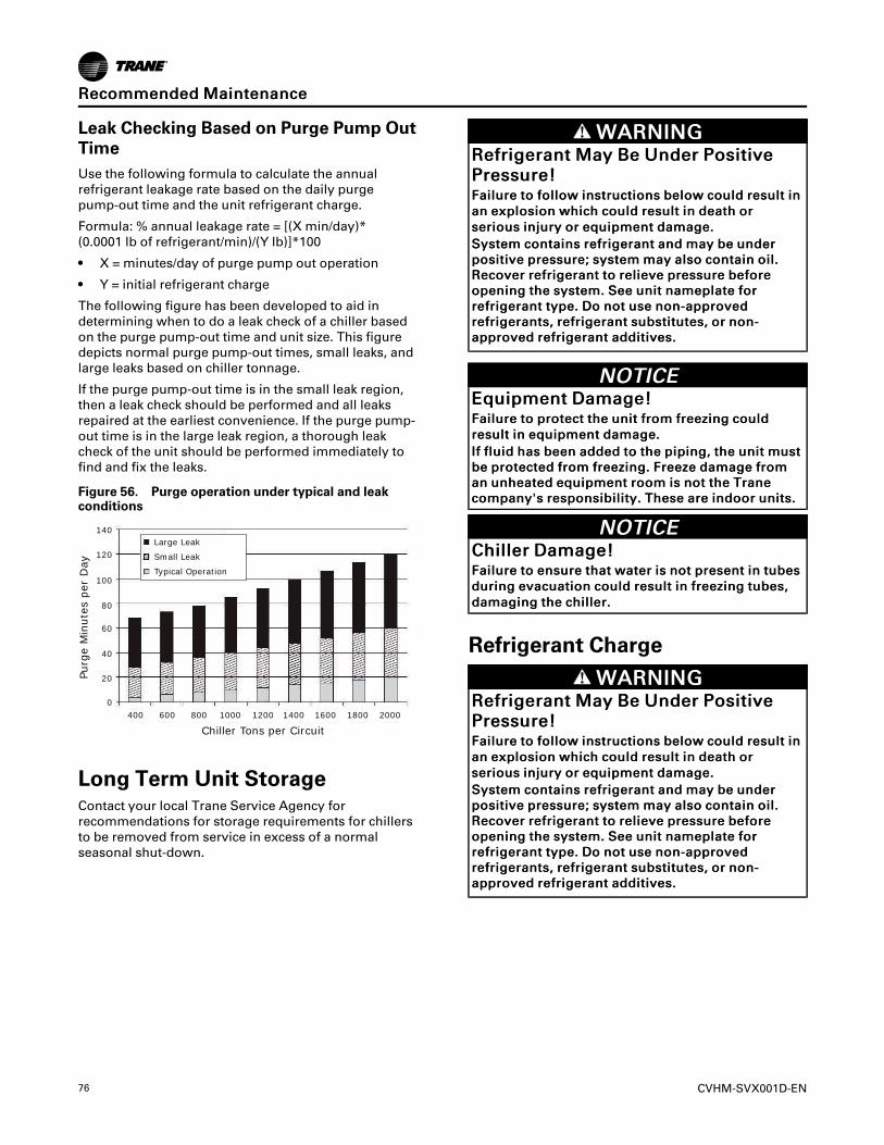
76 CVHM-SVX001D-EN
Leak Checking Based on Purge Pump OutTimeUse the following formula to calculate the annualrefrigerant leakage rate based on the daily purgepump-out time and the unit refrigerant charge.
Formula: % annual leakage rate = [(X min/day)*(0.0001 lb of refrigerant/min)/(Y lb)]*100
• X = minutes/day of purge pump out operation
• Y = initial refrigerant charge
The following figure has been developed to aid indetermining when to do a leak check of a chiller basedon the purge pump-out time and unit size. This figuredepicts normal purge pump-out times, small leaks, andlarge leaks based on chiller tonnage.
If the purge pump-out time is in the small leak region,then a leak check should be performed and all leaksrepaired at the earliest convenience. If the purge pump-out time is in the large leak region, a thorough leakcheck of the unit should be performed immediately tofind and fix the leaks.
Figure 56. Purge operation under typical and leakconditions
Large Leak
Small Leak
Typical Operation
Purg
e M
inute
s per
Day
Chiller Tons per Circuit
140
120
100
80
60
40
20
0400 600 800 1000 1200 1400 1600 1800 2000
Long Term Unit StorageContact your local Trane Service Agency forrecommendations for storage requirements for chillersto be removed from service in excess of a normalseasonal shut-down.
WWAARRNNIINNGGRReeffrriiggeerraanntt MMaayy BBee UUnnddeerr PPoossiittiivveePPrreessssuurree!!FFaaiilluurree ttoo ffoollllooww iinnssttrruuccttiioonnss bbeellooww ccoouulldd rreessuulltt iinnaann eexxpplloossiioonn wwhhiicchh ccoouulldd rreessuulltt iinn ddeeaatthh oorrsseerriioouuss iinnjjuurryy oorr eeqquuiippmmeenntt ddaammaaggee..SSyysstteemm ccoonnttaaiinnss rreeffrriiggeerraanntt aanndd mmaayy bbee uunnddeerrppoossiittiivvee pprreessssuurree;; ssyysstteemm mmaayy aallssoo ccoonnttaaiinn ooiill..RReeccoovveerr rreeffrriiggeerraanntt ttoo rreelliieevvee pprreessssuurree bbeeffoorreeooppeenniinngg tthhee ssyysstteemm.. SSeeee uunniitt nnaammeeppllaattee ffoorrrreeffrriiggeerraanntt ttyyppee.. DDoo nnoott uussee nnoonn--aapppprroovveeddrreeffrriiggeerraannttss,, rreeffrriiggeerraanntt ssuubbssttiittuutteess,, oorr nnoonn--aapppprroovveedd rreeffrriiggeerraanntt aaddddiittiivveess..
NNOOTTIICCEEEEqquuiippmmeenntt DDaammaaggee!!FFaaiilluurree ttoo pprrootteecctt tthhee uunniitt ffrroomm ffrreeeezziinngg ccoouullddrreessuulltt iinn eeqquuiippmmeenntt ddaammaaggee..IIff fflluuiidd hhaass bbeeeenn aaddddeedd ttoo tthhee ppiippiinngg,, tthhee uunniitt mmuussttbbee pprrootteecctteedd ffrroomm ffrreeeezziinngg.. FFrreeeezzee ddaammaaggee ffrroommaann uunnhheeaatteedd eeqquuiippmmeenntt rroooomm iiss nnoott tthhee TTrraanneeccoommppaannyy''ss rreessppoonnssiibbiilliittyy.. TThheessee aarree iinnddoooorr uunniittss..
NNOOTTIICCEECChhiilllleerr DDaammaaggee!!FFaaiilluurree ttoo eennssuurree tthhaatt wwaatteerr iiss nnoott pprreesseenntt iinn ttuubbeessdduurriinngg eevvaaccuuaattiioonn ccoouulldd rreessuulltt iinn ffrreeeezziinngg ttuubbeess,,ddaammaaggiinngg tthhee cchhiilllleerr..
Refrigerant Charge
WWAARRNNIINNGGRReeffrriiggeerraanntt MMaayy BBee UUnnddeerr PPoossiittiivveePPrreessssuurree!!FFaaiilluurree ttoo ffoollllooww iinnssttrruuccttiioonnss bbeellooww ccoouulldd rreessuulltt iinnaann eexxpplloossiioonn wwhhiicchh ccoouulldd rreessuulltt iinn ddeeaatthh oorrsseerriioouuss iinnjjuurryy oorr eeqquuiippmmeenntt ddaammaaggee..SSyysstteemm ccoonnttaaiinnss rreeffrriiggeerraanntt aanndd mmaayy bbee uunnddeerrppoossiittiivvee pprreessssuurree;; ssyysstteemm mmaayy aallssoo ccoonnttaaiinn ooiill..RReeccoovveerr rreeffrriiggeerraanntt ttoo rreelliieevvee pprreessssuurree bbeeffoorreeooppeenniinngg tthhee ssyysstteemm.. SSeeee uunniitt nnaammeeppllaattee ffoorrrreeffrriiggeerraanntt ttyyppee.. DDoo nnoott uussee nnoonn--aapppprroovveeddrreeffrriiggeerraannttss,, rreeffrriiggeerraanntt ssuubbssttiittuutteess,, oorr nnoonn--aapppprroovveedd rreeffrriiggeerraanntt aaddddiittiivveess..
RReeccoommmmeennddeedd MMaaiinntteennaannccee
CVHM-SVX001D-EN 77
NNOOTTIICCEEEEqquuiippmmeenntt DDaammaaggee!!MMiixxiinngg rreeffrriiggeerraannttss oorr ooiillss ccoouulldd rreessuulltt iinneeqquuiippmmeenntt ddaammaaggee iinncclluuddiinngg bbeeaarriinngg ddaammaaggee,,iinnttrroodduuccttiioonn ooff aacciiddss iinnttoo tthhee cchhiilllleerr,, oorr ccoonnttiinnuuoouussppuurrggee ppuummpp--oouutt iinn hhiigghh--hheeaadd//hhiigghh aammbbiieennttaapppplliiccaattiioonnss..CCeennTTrraaVVaacc cchhiilllleerrss aarree mmaannuuffaaccttuurreedd wwiitthhddiiffffeerreenntt rreeffrriiggeerraanntt//ooiill ssyysstteemmss:: 11)) cchhiilllleerrss uussiinnggRR--112233 rreeffrriiggeerraanntt aanndd OOIILL0000002222 ccoommpprreessssoorr ooiill,,aanndd 22)) cchhiilllleerrss uussiinngg RR--551144AA rreeffrriiggeerraanntt aannddOOIILL0000333344//OOIILL0000333355 ccoommpprreessssoorr ooiill..VVeerriiffyy pprrooppeerr rreeffrriiggeerraanntt aanndd ooiill ffoorr yyoouurr cchhiilllleerraanndd ddoo NNOOTT mmiixx rreeffrriiggeerraannttss oorr ooiillss!!
This Installation, Operation, and Maintenancemanualapplies to CenTraVac™ chillers with R-514A refrigerantand OIL00334/OIL00335 compressor oil.
IImmppoorrttaanntt:: Verify proper refrigerant and compressoroil for your chiller before proceeding!
Refer to Installation, Operation, and Maintenance: R-514A Low-Pressure Refrigerant Handling GuidelinesConservation and Safe Handling of R-514A Refrigerantin Trane Chillers for Service Technicians (CTV-SVX008*-EN)
Leak Testing
WWAARRNNIINNGGEExxpplloossiioonn HHaazzaarrdd!!FFaaiilluurree ttoo ffoollllooww ssaaffee lleeaakk tteesstt pprroocceedduurreess bbeelloowwccoouulldd rreessuulltt iinn ddeeaatthh oorr sseerriioouuss iinnjjuurryy oorreeqquuiippmmeenntt oorr pprrooppeerrttyy--oonnllyy--ddaammaaggee..NNeevveerr uussee aann ooppeenn ffllaammee ttoo ddeetteecctt ggaass lleeaakkss.. UUssee aalleeaakk tteesstt ssoolluuttiioonn ffoorr lleeaakk tteessttiinngg..
WWAARRNNIINNGGHHaazzaarrddoouuss PPrreessssuurreess!!FFaaiilluurree ttoo ffoollllooww iinnssttrruuccttiioonnss bbeellooww ccoouulldd rreessuulltt iinnaa vviioolleenntt eexxpplloossiioonn,, wwhhiicchh ccoouulldd rreessuulltt iinn ddeeaatthh oorrsseerriioouuss iinnjjuurryy..IIff aa hheeaatt ssoouurrccee iiss rreeqquuiirreedd ttoo rraaiissee tthhee ttaannkkpprreessssuurree dduurriinngg rreemmoovvaall ooff rreeffrriiggeerraanntt ffrroommccyylliinnddeerrss,, uussee oonnllyy wwaarrmm wwaatteerr oorr hheeaatt bbllaannkkeettss ttoorraaiissee tthhee ttaannkk tteemmppeerraattuurree.. DDoo nnoott eexxcceeeedd aatteemmppeerraattuurree ooff 115500°°FF.. DDoo nnoott uunnddeerr aannyycciirrccuummssttaanncceess aappppllyy ddiirreecctt ffllaammee ttoo aannyy ppoorrttiioonn oofftthhee ccyylliinnddeerr..
IImmppoorrttaanntt:: If leak testing is required, contact a TraneService Agency.
Recommended SystemMaintenance
NNOOTTIICCEEPPrrooppeerr WWaatteerr TTrreeaattmmeenntt RReeqquuiirreedd!!TThhee uussee ooff uunnttrreeaatteedd oorr iimmpprrooppeerrllyy ttrreeaatteedd wwaatteerrccoouulldd rreessuulltt iinn ssccaalliinngg,, eerroossiioonn,, ccoorrrroossiioonn,, aallggaaee oorrsslliimmee..UUssee tthhee sseerrvviicceess ooff aa qquuaalliiffiieedd wwaatteerr ttrreeaattmmeennttssppeecciiaalliisstt ttoo ddeetteerrmmiinnee wwhhaatt wwaatteerr ttrreeaattmmeenntt,, iiffaannyy,, iiss rreeqquuiirreedd.. TTrraannee aassssuummeess nnoo rreessppoonnssiibbiilliittyyffoorr eeqquuiippmmeenntt ffaaiilluurreess wwhhiicchh rreessuulltt ffrroomm uunnttrreeaatteeddoorr iimmpprrooppeerrllyy ttrreeaatteedd wwaatteerr,, oorr ssaalliinnee oorr bbrraacckkiisshhwwaatteerr..
CondenserCondenser tube fouling is indicated when the approachtemperature (the difference between the condensingrefrigerant temperature and the leaving condenserwater temperature) is higher than predicted.
If the annual condenser tube inspection indicates thatthe tubes are fouled, two cleaning methods—mechanical and chemical—can be used to rid the tubesof contaminants. Use the mechanical cleaning methodto remove sludge and loose material from smooth-boretubes.
To clean other types of tubes including internally-enhanced types, consult a qualified serviceorganization for recommendations.
Figure 57. Typical chemical cleaning setup
PipeConnections
ShutoffValves
CleaningSolution
CirculatorPump
1. Follow all instructions in “Waterbox Removal andInstallation,” p. 81 to remove waterbox covers.
2. Work a round nylon or brass bristled brush(attached to a rod) in and out of each of thecondenser water tubes to loosen the sludge.
3. Thoroughly flush the condenser water tubes withclean water.
RReeccoommmmeennddeedd MMaaiinntteennaannccee
78 CVHM-SVX001D-EN
4. Scale deposits are best removed by chemicalmeans. Be sure to consult any qualified chemicalhouse in the area (one familiar with the local watersupply’s chemical mineral content) for arecommended cleaning solution suitable for thejob.
NNoottee:: A standard condenser water circuit iscomposed solely of copper, cast iron, andsteel.
NNOOTTIICCEEUUnniitt CCoorrrroossiioonn DDaammaaggee!!FFaaiilluurree ttoo ffoollllooww iinnssttrruuccttiioonnss bbeellooww ccoouulldd rreessuulltt iinnccoorrrroossiioonn ddaammaaggee ttoo tthhee uunniitt aanndd ttuubbeess..FFoollllooww pprrooppeerr pprroocceedduurreess wwhheenn uussiinngg ccoorrrroossiivveecchheemmiiccaallss ttoo cclleeaann wwaatteerr ssiiddee ooff uunniitt.. IIff uunnssuurree,, iittiiss rreeccoommmmeennddeedd tthhaatt tthhee sseerrvviicceess ooff aa qquuaalliiffiieeddcchheemmiiccaall cclleeaanniinngg ffiirrmm bbee uusseedd..
IImmppoorrttaanntt:: All of the materials used in the externalcirculation system, the quantity of thesolution, the duration of the cleaningperiod, and any required safety precautionsshould be approved by the companyfurnishing the materials or performing thecleaning. Remember, however, thatwhenever the chemical tube cleaningmethod is used, it must be followed upwith mechanical tube cleaning, flushing,and inspection.
EvaporatorSince the evaporator is typically part of a closed circuit,it may not accumulate appreciable amounts of scale orsludge. Normally, cleaning every three years issufficient. However, periodic inspection and cleaning isrecommended on open evaporator systems, such as airwashers.
Waterbox and Tubesheet ProtectiveCoatingsTrane recommends that coated waterboxes/tubesheets—regardless of the type of protective coating included—be taken out of service within the first one to threemonths of operation for inspection. Any voids ordefects identified upon inspection must be repaired. Ifthe water quality is known to be highly supportive ofcorrosion (i.e., sea water, etc.), inspect the coatingsystem at one month; if the water quality is known tobe relatively benign (i.e., normal treated and cleancondenser water), inspect the coating system withinthree months. Only when initial inspections show noproblems are present should subsequent maintenanceintervals be increased.
Sacrificial AnodesThe replacement schedule for the optional zinc ormagnesium anodes can vary greatly with the
aggressiveness of the water that is in the system. Somesites could require anode replacement every two tothree months while other sites may require anodereplacement every two to three years. Tranerecommends inspection of anodes for wear sometimewithin the first several months of the anodes beingplaced into service. If the observed loss of anodematerial is small, then the interval between subsequentinspections can be lengthened. Replace the anode and/or shorten the inspection interval if the anode has lost50 percent or more of its original mass. If anodedepletion occurs very quickly, consult a watertreatment specialist to determine if the anode materialselected is correct for the application.
NNOOTTIICCEEEEqquuiippmmeenntt DDaammaaggee!!FFaaiilluurree ttoo ffoollllooww iinnssttrruuccttiioonnss ccoouulldd rreessuulltt iinneeqquuiippmmeenntt ddaammaaggee..DDoo NNOOTT uussee TTeefflloonn--bbaasseedd ttaappee oorr ppaassttee oonn aannooddee;;aa ssmmaallll aammoouunntt ooff lliiqquuiidd sseeaallaanntt ((LLooccttiittee®® 224422 oorreeqquuiivvaalleenntt)) mmaayy bbee aapppplliieedd ttoo pprreevveenntt lleeaakkaaggeewwhheenn iinnssttaalllliinngg aann aannooddee,, bbuutt ddoo nnoott aappppllyy ssoommuucchh sseeaallaanntt tthhaatt iitt pprreevveennttss tthhee nneecceessssaarryyeelleeccttrriiccaall ccoonnnneeccttiioonn bbeettwweeeenn tthhee aannooddee aanndd tthheewwaatteerrbbooxx..
As needed after draining the waterbox, use a 2-1/2 in.(63.5 mm) wrench to remove/install Trane-suppliedwaterbox anodes.
Adaptive Frequency DriveVisual Inspection—Power Removed
WWAARRNNIINNGGHHaazzaarrddoouuss VVoollttaaggee ww//CCaappaacciittoorrss!!FFaaiilluurree ttoo ddiissccoonnnneecctt ppoowweerr aanndd ddiisscchhaarrggeeccaappaacciittoorrss bbeeffoorree sseerrvviicciinngg ccoouulldd rreessuulltt iinn ddeeaatthh oorrsseerriioouuss iinnjjuurryy..DDiissccoonnnneecctt aallll eelleeccttrriicc ppoowweerr,, iinncclluuddiinngg rreemmootteeddiissccoonnnneeccttss aanndd ddiisscchhaarrggee aallll mmoottoorr ssttaarrtt//rruunnccaappaacciittoorrss bbeeffoorree sseerrvviicciinngg.. FFoollllooww pprrooppeerrlloocckkoouutt//ttaaggoouutt pprroocceedduurreess ttoo eennssuurree tthhee ppoowweerrccaannnnoott bbee iinnaaddvveerrtteennttllyy eenneerrggiizzeedd.. FFoorr vvaarriiaabblleeffrreeqquueennccyy ddrriivveess oorr ootthheerr eenneerrggyy ssttoorriinnggccoommppoonneennttss pprroovviiddeedd bbyy TTrraannee oorr ootthheerrss,, rreeffeerr ttootthhee aapppprroopprriiaattee mmaannuuffaaccttuurreerr’’ss lliitteerraattuurree ffoorraalllloowwaabbllee wwaaiittiinngg ppeerriiooddss ffoorr ddiisscchhaarrggee ooffccaappaacciittoorrss.. VVeerriiffyy wwiitthh aa CCAATT IIIIII oorr IIVV vvoollttmmeetteerrrraatteedd ppeerr NNFFPPAA 7700EE tthhaatt aallll ccaappaacciittoorrss hhaavveeddiisscchhaarrggeedd..FFoorr aaddddiittiioonnaall iinnffoorrmmaattiioonn rreeggaarrddiinngg tthhee ssaaffeeddiisscchhaarrggee ooff ccaappaacciittoorrss,, sseeee PPRROODD--SSVVBB0066**--EENN..
1. Check the water/glycol coolant lines and SAE fittingconnections to ensure they are tight and do notleak.
RReeccoommmmeennddeedd MMaaiinntteennaannccee
CVHM-SVX001D-EN 79
2. Ensure the door interlocks are present and working.
3. Verify the safety ground connections to the doorpanels are securely connected.
4. Inspect power wire cables and devices to assure noabrasion is occurring from vibrations againstchassis of cabinets, or other edges.
5. Ensure the drive interior and exterior is clear of anydust or debris. Fans, circuit boards, vents etc. mustbe clean. Only use a vacuum for cleaning. Do NOTuse compressed air.
6. Inspect the interior of the drive for any signs ofmoisture entry or leakage.
7. Visually inspect all drive components and wiring.Look for signs of heat or failure (look for swelled orleaking capacitors, discolored reactors or inductors,broken pre-charge resistors, smoke, or arc trails onMOVs and capacitors, etc.).
8. Closely inspect the motor terminal board for anysigns of leakage, arcing, etc.
9. Check ALL cable/lug/terminal connections insidethe drive enclosure. Ensure all are clean and tight,and not rubbing against each other anywhere.
10. Re-seat all ribbon cable or control wire plugs toensure all are snug and tight.
Drive Cooling Fluid Service Intervals
NNOOTTIICCEEEEqquuiippmmeenntt DDaammaaggee!!FFaaiilluurree ttoo ffoollllooww iinnssttrruuccttiioonnss ccoouulldd rreessuulltt iinneeqquuiippmmeenntt ddaammaaggee..DDrriivvee ccoooolliinngg fflluuiidd aanndd ssttrraaiinneerr mmuusstt bbee sseerrvviicceeddeevveerryy ffiivvee ((55)) yyeeaarrss..
• Every (5) years, contact your local Trane ServiceAgency to service the drive fluid and strainer.
• On a yearly basis, perform a fluid pH test.
Operational Inspection—Power Applied
WWAARRNNIINNGGLLiivvee EElleeccttrriiccaall CCoommppoonneennttss!!FFaaiilluurree ttoo ffoollllooww aallll eelleeccttrriiccaall ssaaffeettyy pprreeccaauuttiioonnsswwhheenn eexxppoosseedd ttoo lliivvee eelleeccttrriiccaall ccoommppoonneennttss ccoouullddrreessuulltt iinn ddeeaatthh oorr sseerriioouuss iinnjjuurryy..WWhheenn iitt iiss nneecceessssaarryy ttoo wwoorrkk wwiitthh lliivvee eelleeccttrriiccaallccoommppoonneennttss,, hhaavvee aa qquuaalliiffiieedd lliicceennsseedd eelleeccttrriicciiaannoorr ootthheerr iinnddiivviidduuaall wwhhoo hhaass bbeeeenn pprrooppeerrllyy ttrraaiinneeddiinn hhaannddlliinngg lliivvee eelleeccttrriiccaall ccoommppoonneennttss ppeerrffoorrmmtthheessee ttaasskkss..
1. Verify the drive cabinet cooling fans are operating.
This should be done from outside the enclosure, bylooking into the cabinet at door and cabinet vents,to avoid electrical hazards.
NNoottee:: The power module fan comes on with power.Other fans cycle with drive operation.
2. Check historic fault codes using Tracer® TU.
3. Check configuration settings and confirm all propersettings are still present in the controls.
4. Review the diagnostic history.
5. Create a Chiller Service Report to document allsetpoints.
6. Check the UC800 alarm histories for any indicationsof operational problems.
Routine MaintenanceThe Adaptive Frequency™ Drive (AFD) requiresminimal routine maintenance. A routine visualinspection every one to two years is adequate.
WWAARRNNIINNGGHHaazzaarrddoouuss VVoollttaaggee ww//CCaappaacciittoorrss!!FFaaiilluurree ttoo ddiissccoonnnneecctt ppoowweerr aanndd ddiisscchhaarrggeeccaappaacciittoorrss bbeeffoorree sseerrvviicciinngg ccoouulldd rreessuulltt iinn ddeeaatthh oorrsseerriioouuss iinnjjuurryy..DDiissccoonnnneecctt aallll eelleeccttrriicc ppoowweerr,, iinncclluuddiinngg rreemmootteeddiissccoonnnneeccttss aanndd ddiisscchhaarrggee aallll mmoottoorr ssttaarrtt//rruunnccaappaacciittoorrss bbeeffoorree sseerrvviicciinngg.. FFoollllooww pprrooppeerrlloocckkoouutt//ttaaggoouutt pprroocceedduurreess ttoo eennssuurree tthhee ppoowweerrccaannnnoott bbee iinnaaddvveerrtteennttllyy eenneerrggiizzeedd.. FFoorr vvaarriiaabblleeffrreeqquueennccyy ddrriivveess oorr ootthheerr eenneerrggyy ssttoorriinnggccoommppoonneennttss pprroovviiddeedd bbyy TTrraannee oorr ootthheerrss,, rreeffeerr ttootthhee aapppprroopprriiaattee mmaannuuffaaccttuurreerr’’ss lliitteerraattuurree ffoorraalllloowwaabbllee wwaaiittiinngg ppeerriiooddss ffoorr ddiisscchhaarrggee ooffccaappaacciittoorrss.. VVeerriiffyy wwiitthh aa CCAATT IIIIII oorr IIVV vvoollttmmeetteerrrraatteedd ppeerr NNFFPPAA 7700EE tthhaatt aallll ccaappaacciittoorrss hhaavveeddiisscchhaarrggeedd..FFoorr aaddddiittiioonnaall iinnffoorrmmaattiioonn rreeggaarrddiinngg tthhee ssaaffeeddiisscchhaarrggee ooff ccaappaacciittoorrss,, sseeee PPRROODD--SSVVBB0066**--EENN..
WWAARRNNIINNGGHHaazzaarrddoouuss VVoollttaaggee ww//CCaappaacciittoorrss!!FFaaiilluurree ttoo ffoollllooww iinnssttrruuccttiioonnss bbeellooww ccoouulldd rreessuulltt iinnddeeaatthh oorr sseerriioouuss iinnjjuurryy..DDiissccoonnnneecctt aallll eelleeccttrriicc ppoowweerr,, iinncclluuddiinngg rreemmootteeddiissccoonnnneeccttss aanndd wwaaiitt ffoorr DDCC ccaappaacciittoorrss ttooddiisscchhaarrggee bbeeffoorree sseerrvviicciinngg.. RReeffeerr ttoo tthheemmaannuuffaaccttuurreerr’’ss rreeccoommmmeennddaattiioonnss ffoorr pprrooppeerrddiisscchhaarrggee ttiimmee aass DDCC bbuuss ccaappaacciittoorrss rreettaaiinnhhaazzaarrddoouuss vvoollttaaggeess aafftteerr iinnppuutt ppoowweerr hhaass bbeeeennddiissccoonnnneecctteedd.. FFoollllooww pprrooppeerr lloocckkoouutt// ttaaggoouuttpprroocceedduurreess ttoo eennssuurree tthhee ppoowweerr ccaannnnoott bbeeiinnaaddvveerrtteennttllyy eenneerrggiizzeedd.. VVeerriiffyy wwiitthh aa CCAATT IIIIII oorr IIVVvvoollttmmeetteerr rraatteedd ppeerr NNFFPPAA 7700EE tthhaatt aallll ccaappaacciittoorrsshhaavvee ddiisscchhaarrggeedd bbeeffoorree ttoouucchhiinngg aannyy iinntteerrnnaallccoommppoonneennttss..FFoorr aaddddiittiioonnaall iinnffoorrmmaattiioonn rreeggaarrddiinngg tthhee ssaaffeeddiisscchhaarrggee ooff ccaappaacciittoorrss,, sseeee PPRROODD--SSVVBB0066**--EENN..
Perform a visual inspection including the following:
RReeccoommmmeennddeedd MMaaiinntteennaannccee
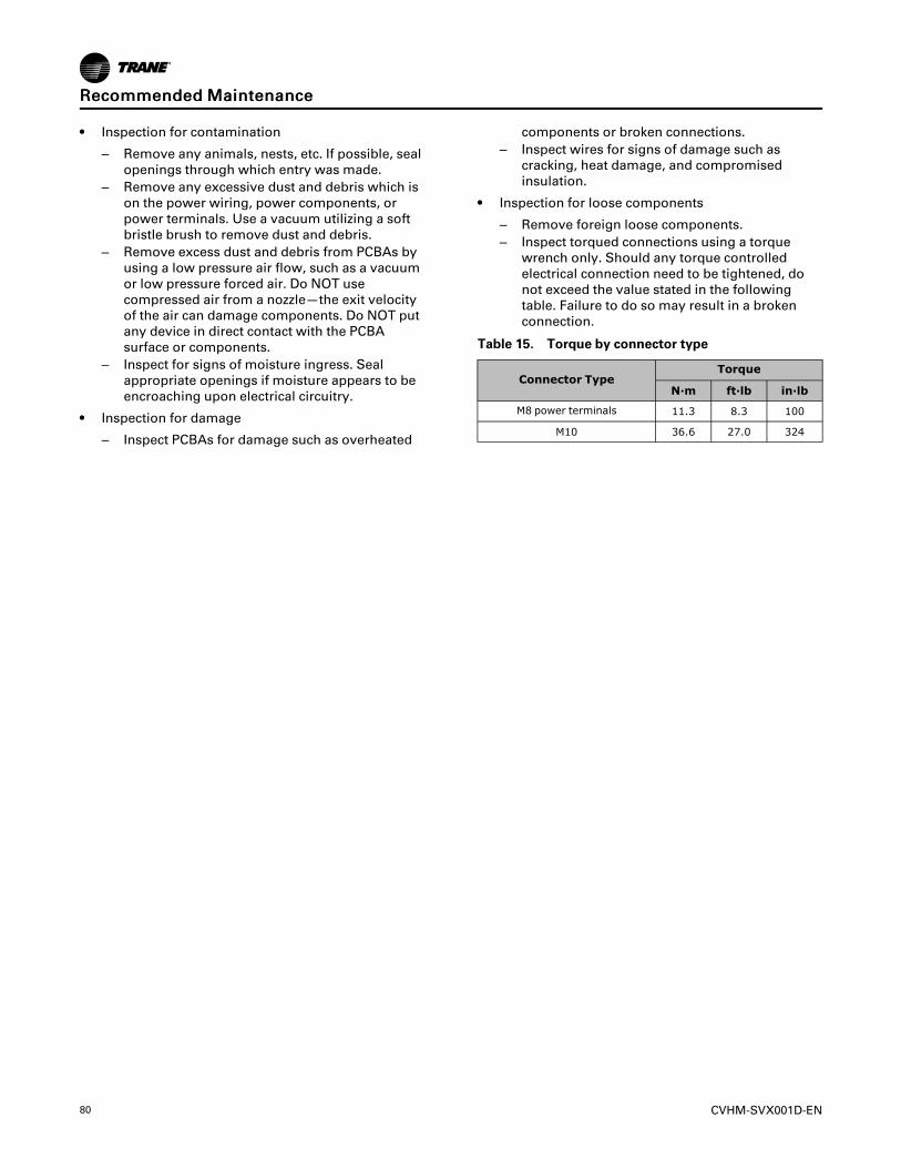
80 CVHM-SVX001D-EN
• Inspection for contamination
– Remove any animals, nests, etc. If possible, sealopenings through which entry was made.
– Remove any excessive dust and debris which ison the power wiring, power components, orpower terminals. Use a vacuum utilizing a softbristle brush to remove dust and debris.
– Remove excess dust and debris from PCBAs byusing a low pressure air flow, such as a vacuumor low pressure forced air. Do NOT usecompressed air from a nozzle—the exit velocityof the air can damage components. Do NOT putany device in direct contact with the PCBAsurface or components.
– Inspect for signs of moisture ingress. Sealappropriate openings if moisture appears to beencroaching upon electrical circuitry.
• Inspection for damage
– Inspect PCBAs for damage such as overheated
components or broken connections.– Inspect wires for signs of damage such as
cracking, heat damage, and compromisedinsulation.
• Inspection for loose components
– Remove foreign loose components.– Inspect torqued connections using a torque
wrench only. Should any torque controlledelectrical connection need to be tightened, donot exceed the value stated in the followingtable. Failure to do so may result in a brokenconnection.
Table 15. Torque by connector type
Connector TypeTorque
N·m ft·lb in·lb
M8 power terminals 11.3 8.3 100
M10 36.6 27.0 324
RReeccoommmmeennddeedd MMaaiinntteennaannccee
CVHM-SVX001D-EN 81
Waterbox Removal and InstallationIImmppoorrttaanntt:: Only qualified technicians should perform
the installation and servicing of thisequipment.
DiscussionThis section will discuss recommended hoist ring/clevises and lifting. Proper lifting technique will varybased on mechanical room layout.
• It is the responsibility of the person(s) performingthe work to be properly trained in the safe practiceof rigging, lifting, securing, and fastening of thewaterbox.
• It is the responsibility of the person(s) providingand using the rigging and lifting devices to inspectthese devices to ensure they are free from defectand are rated to meet or exceed the publishedweight of the waterbox.
• Always use rigging and lifting devices inaccordance with the applicable instructions for suchdevice.
ProcedureWWAARRNNIINNGG
HHeeaavvyy OObbjjeeccttss!!FFaaiilluurree ttoo pprrooppeerrllyy lliifftt wwaatteerrbbooxx ccoouulldd rreessuulltt iinnddeeaatthh oorr sseerriioouuss iinnjjuurryy..EEaacchh ooff tthhee iinnddiivviidduuaall ccaabblleess ((cchhaaiinnss oorr sslliinnggss))uusseedd ttoo lliifftt tthhee wwaatteerrbbooxx mmuusstt bbee ccaappaabbllee ooffssuuppppoorrttiinngg tthhee eennttiirree wweeiigghhtt ooff tthhee wwaatteerrbbooxx.. TThheeccaabblleess ((cchhaaiinnss oorr sslliinnggss)) mmuusstt bbee rraatteedd ffoorroovveerrhheeaadd lliiffttiinngg aapppplliiccaattiioonnss wwiitthh aann aacccceeppttaabblleewwoorrkkiinngg llooaadd lliimmiitt.. RReeffeerr ttoo tthhee ttaabbllee ffoorr wwaatteerrbbooxxwweeiigghhttss..
NNoottee:: Refer to“Torque Requirements and WaterboxWeights,” p. 82 for waterbox weights.
WWAARRNNIINNGGSSttrraaiigghhtt VVeerrttiiccaall LLiifftt RReeqquuiirreedd!!FFaaiilluurree ttoo pprrooppeerrllyy lliifftt wwaatteerrbbooxx iinn ssttrraaiigghhtt vveerrttiiccaalllliifftt ccoouulldd ccaauussee tthhee eeyyeebboollttss ttoo bbrreeaakk wwhhiicchh ccoouullddrreessuulltt iinn ddeeaatthh oorr sseerriioouuss iinnjjuurryy ffrroomm oobbjjeeccttddrrooppppiinngg..TThhee pprrooppeerr uussee aanndd rraattiinnggss ffoorr eeyyeebboollttss ccaann bbeeffoouunndd iinn AANNSSII//AASSMMEE ssttaannddaarrdd BB1188..1155.. MMaaxxiimmuummllooaadd rraattiinngg ffoorr eeyyeebboollttss aarree bbaasseedd oonn aa ssttrraaiigghhttvveerrttiiccaall lliifftt iinn aa ggrraadduuaallllyy iinnccrreeaassiinngg mmaannnneerr..AAnngguullaarr lliiffttss wwiillll ssiiggnniiffiiccaannttllyy lloowweerr mmaaxxiimmuummllooaaddss aanndd sshhoouulldd bbee aavvooiiddeedd wwhheenneevveerr ppoossssiibbllee..LLooaaddss sshhoouulldd aallwwaayyss bbee aapppplliieedd ttoo eeyyeebboollttss iinn tthheeppllaannee ooff tthhee eeyyee,, nnoott aatt ssoommee aannggllee ttoo tthhiiss ppllaannee..
Review mechanical room limitations and determine the
safest method or methods of rigging and lifting thewaterboxes.
1. Determine the type and size of chiller beingserviced. Refer to Trane® nameplate located onchiller control panel.
IImmppoorrttaanntt:: This section contains rigging and liftinginformation only for Trane CenTraVac™chillers built in La Crosse. For TraneCenTraVac™ chillers built outside theUnited States, refer to literatureprovided by the applicablemanufacturing location.
2. Select the proper lift connection device from thetable in “Connection Devices Information,” p. 83.The rated lifting capacity of the selected liftconnection device must meet or exceed thepublished weight of the waterbox. Verify thewaterbox weight from the latest publishedliterature.
3. Ensure that the lift connection device has thecorrect connection for the waterbox (e.g., threadtype [course/fine, English/metric] and screwdiameter [English/metric]).
4. Properly connect the lift connection device to thewaterbox. Refer to the following figure and ensurethat the lift connection device is securely fastened.
5. Disconnect water pipes, if connected.
6. Remove hex head bolts.
7. Lift the waterbox away from the shell.
WWAARRNNIINNGGOOvveerrhheeaadd HHaazzaarrdd!!FFaaiilluurree ttoo ffoollllooww iinnssttrruuccttiioonnss ccoouulldd rreessuulltt iinnddeeaatthh oorr sseerriioouuss iinnjjuurriieess..NNeevveerr ssttaanndd bbeellooww oorr iinn cclloossee pprrooxxiimmiittyy ttoohheeaavvyy oobbjjeeccttss wwhhiillee tthheeyy aarree ssuussppeennddeedd ffrroomm,,oorr bbeeiinngg lliifftteedd bbyy,, aa lliiffttiinngg ddeevviiccee iinn ccaassee tthheeoobbjjeecctt ddrrooppss..
8. Store waterbox in a safe and secure location andposition.
NNoottee:: Do NOT leave waterbox suspended fromlifting device.
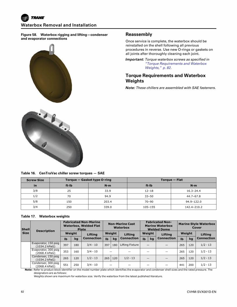
82 CVHM-SVX001D-EN
Figure 58. Waterbox rigging and lifting—condenserand evaporator connections
ReassemblyOnce service is complete, the waterbox should bereinstalled on the shell following all previousprocedures in reverse. Use new O-rings or gaskets onall joints after thoroughly cleaning each joint.
IImmppoorrttaanntt:: Torque waterbox screws as specified in“Torque Requirements and WaterboxWeights,” p. 82.
Torque Requirements and WaterboxWeightsNNoottee:: These chillers are assembled with SAE fasteners.
Table 16. CenTraVac chiller screw torques — SAE
Screw Size Torque— Gasket type O-ring Torque— Flat
in ft·lb N·m ft·lb N·m
3/8 25 33.9 12–18 16.3–24.4
1/2 70 94.9 33–50 44.7–67.8
5/8 150 203.4 70–90 94.9–122.0
3/4 250 339.0 105–155 142.4–210.2
Table 17. Waterbox weights
ShellSize
Description
Fabricated Non-MarineWaterbox, Welded Flat
Plate
Non-Marine CastWaterbox
Fabricated Non-MarineWaterboxWelded Dome
Marine StyleWaterboxCover
Weight LiftingConnection
Weight LiftingConnection
Weight LiftingConnection
Weight LiftingConnectionlb kg lb kg lb kg lb kg
Evaporator, 150 psig(1034.2 kPaG) 397 180 3/4 - 10 397 180 Lifting Fixture — — 265 120 1/2 - 13
Evaporator, 300 psig(2068.4 kPaG) 353 160 3/4 - 10 — — — — 265 120 1/2 - 13
Condenser, 150 psig(1034.2 kPaG) 265 120 1/2 - 13 265 120 1/2 - 13 — — 265 120 1/2 - 13
Condenser, 300 psig(2068.4 kPaG) 551 250 3/4 - 10 — — — — 441 200 1/2 - 13
Note: Refer to product block identifier on the model number plate which identifies the evaporator and condenser shell sizes and the rated pressure. Thedesignators are as follows:Weights shown are maximum for waterbox size. Verify the waterbox from the latest published literature.
WWaatteerrbbooxx RReemmoovvaall aanndd IInnssttaallllaattiioonn
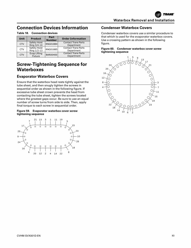
CVHM-SVX001D-EN 83
Connection Devices InformationTable 18. Connection devices
Unit Product PartNumber Order Information
CTVSafety HoistRing 3/4-10 RNG01884
Contact Trane PartsDepartment
CTVSafety HoistRing 1/2-13 RNG01885
Contact Trane PartsDepartment
CTV Evap LiftingFixture BAR00400
Contact Trane PartsDepartment
Screw-Tightening Sequence forWaterboxesEvaporator Waterbox CoversEnsure that the waterbox head rests tightly against thetube sheet, and then snugly tighten the screws insequential order as shown in the following figure. Ifexcessive tube sheet crown prevents the head fromcontacting the tube sheet, tighten the screws locatedwhere the greatest gaps occur. Be sure to use an equalnumber of screw turns from side to side. Then, applyfinal torque to each screw in sequential order.
Figure 59. Evaporator waterbox cover screwtightening sequence
1
24
5
9
20 2
23
3
4 226
7
8
10
19
18
26
25
17
21
16
15
14
13
12
11
Condenser Waterbox CoversCondenser waterbox covers use a similar procedure tothat which is used for the evaporator waterbox covers.Use a crossing pattern as shown in the followingfigure.
Figure 60. Condenser waterbox cover screwtightening sequence
1
24
5 9
20
2
23
3
4
22
6
7
8
10
19
18
1721
16
15
14
13
12
11
WWaatteerrbbooxx RReemmoovvaall aanndd IInnssttaallllaattiioonn
84 CVHM-SVX001D-EN
Adaptive Frequency Drive Removal and InstallationFactory Warranty InformationCompliance with the following is required to preservethe factory warranty:
AAllll UUnniitt IInnssttaallllaattiioonnss
Startup MUST be performed by Trane, or an authorizedagent of Trane, to VALIDATE this WARRANTY.Contractor must provide a two-week startupnotification to Trane (or an agent of Trane specificallyauthorized to perform startup).
AAddddiittiioonnaall RReeqquuiirreemmeennttss ffoorr UUnniittss RReeqquuiirriinnggDDiissaasssseemmbbllyy aanndd RReeaasssseemmbbllyy
When a new chiller is shipped and received from ourTrane manufacturing location and, for any reason, itrequires disassembly or partial disassembly, andreassembly— which could include but is not limited tothe evaporator, condenser, control panel, compressor/motor, economizer, purge, factory-mounted starter orany other components originally attached to the fullyassembled unit— compliance with the following isrequired to preserve the factory warranty:
• Trane, or an agent of Trane specifically authorizedto perform start-up and warranty of Trane®products, will perform or have direct on-site
technical supervision of the disassembly andreassembly work.
• The installing contractor must notify Trane—or anagent of Trane specifically authorized to performstartup and warranty of Trane® products—twoweeks in advance of the scheduled disassemblywork to coordinate the disassembly andreassembly work.
• Start-up must be performed by Trane or an agent ofTrane specifically authorized to perform startup andwarranty of Trane® products.
Trane, or an agent of Trane specifically authorized toperform start-up and warranty of Trane® products, willprovide qualified personnel and standard hand tools toperform the disassembly and reassembly work at alocation specified by the contractor. The contractorshall provide the rigging equipment such as chain falls,gantries, cranes, forklifts, etc. necessary for thedisassembly and reassembly work and the requiredqualified personnel to operate the necessary riggingequipment.
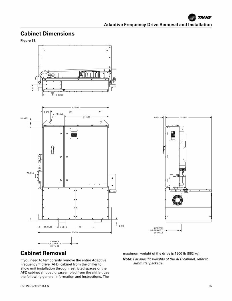
CVHM-SVX001D-EN 85
Cabinet DimensionsFigure 61.
56-5/8
15-11/16 5-5/8 22 1-7/8
CENTEROF GRAVITY
26 TO 31
CENTEROF GRAVITY
10 TO 12
72-5/16
1-11/16
51-5/16
6-1/8 391-3/8
1-3/4 35-7/1634-1/16
5
8-13/16
Cabinet RemovalIf you need to temporarily remove the entire AdaptiveFrequency™ drive (AFD) cabinet from the chiller toallow unit installation through restricted spaces or theAFD cabinet shipped disassembled from the chiller, usethe following general information and instructions. The
maximum weight of the drive is 1900 lb (862 kg).
NNoottee:: For specific weights of the AFD cabinet, refer tosubmittal package.
AAddaappttiivvee FFrreeqquueennccyy DDrriivvee RReemmoovvaall aanndd IInnssttaallllaattiioonn
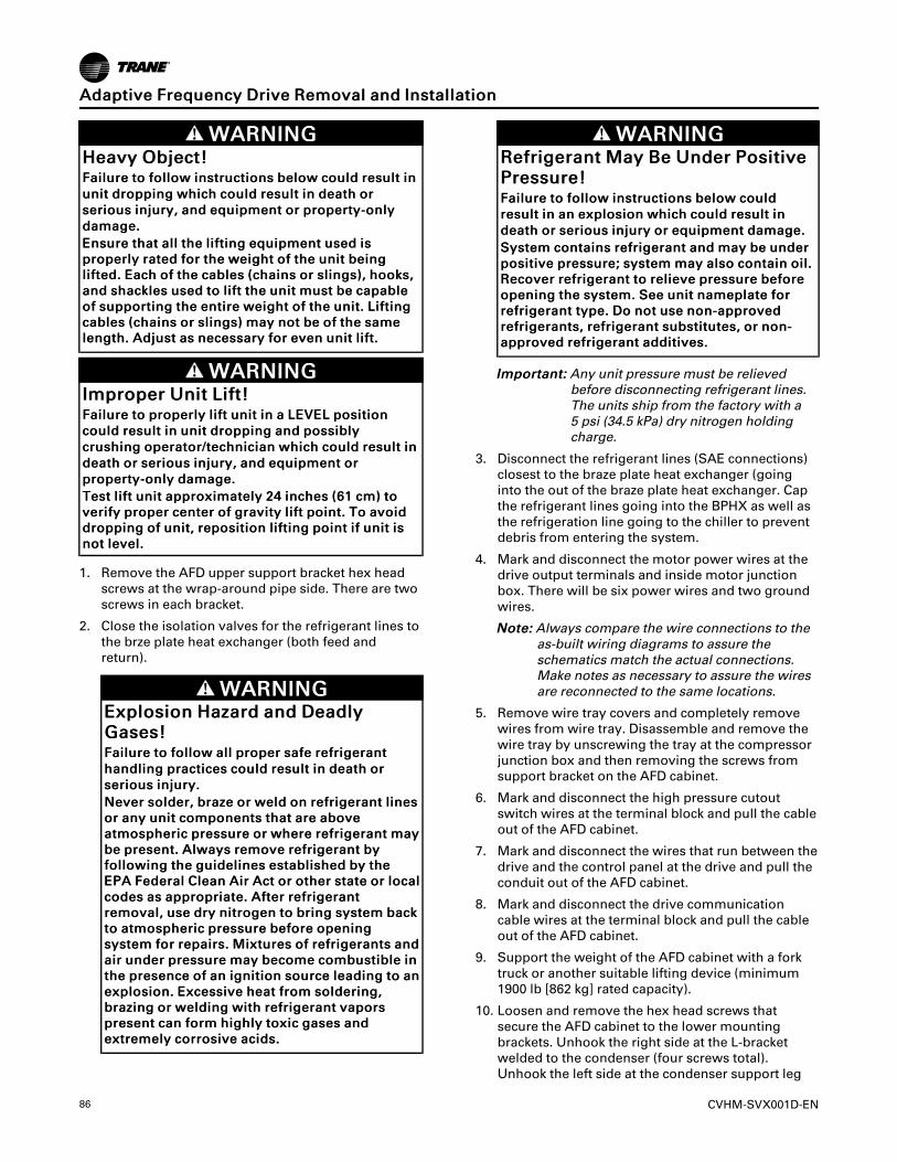
86 CVHM-SVX001D-EN
WWAARRNNIINNGGHHeeaavvyy OObbjjeecctt!!FFaaiilluurree ttoo ffoollllooww iinnssttrruuccttiioonnss bbeellooww ccoouulldd rreessuulltt iinnuunniitt ddrrooppppiinngg wwhhiicchh ccoouulldd rreessuulltt iinn ddeeaatthh oorrsseerriioouuss iinnjjuurryy,, aanndd eeqquuiippmmeenntt oorr pprrooppeerrttyy--oonnllyyddaammaaggee..EEnnssuurree tthhaatt aallll tthhee lliiffttiinngg eeqquuiippmmeenntt uusseedd iisspprrooppeerrllyy rraatteedd ffoorr tthhee wweeiigghhtt ooff tthhee uunniitt bbeeiinngglliifftteedd.. EEaacchh ooff tthhee ccaabblleess ((cchhaaiinnss oorr sslliinnggss)),, hhooookkss,,aanndd sshhaacckklleess uusseedd ttoo lliifftt tthhee uunniitt mmuusstt bbee ccaappaabblleeooff ssuuppppoorrttiinngg tthhee eennttiirree wweeiigghhtt ooff tthhee uunniitt.. LLiiffttiinnggccaabblleess ((cchhaaiinnss oorr sslliinnggss)) mmaayy nnoott bbee ooff tthhee ssaammeelleennggtthh.. AAddjjuusstt aass nneecceessssaarryy ffoorr eevveenn uunniitt lliifftt..
WWAARRNNIINNGGIImmpprrooppeerr UUnniitt LLiifftt!!FFaaiilluurree ttoo pprrooppeerrllyy lliifftt uunniitt iinn aa LLEEVVEELL ppoossiittiioonnccoouulldd rreessuulltt iinn uunniitt ddrrooppppiinngg aanndd ppoossssiibbllyyccrruusshhiinngg ooppeerraattoorr//tteecchhnniicciiaann wwhhiicchh ccoouulldd rreessuulltt iinnddeeaatthh oorr sseerriioouuss iinnjjuurryy,, aanndd eeqquuiippmmeenntt oorrpprrooppeerrttyy--oonnllyy ddaammaaggee..TTeesstt lliifftt uunniitt aapppprrooxxiimmaatteellyy 2244 iinncchheess ((6611 ccmm)) ttoovveerriiffyy pprrooppeerr cceenntteerr ooff ggrraavviittyy lliifftt ppooiinntt.. TToo aavvooiiddddrrooppppiinngg ooff uunniitt,, rreeppoossiittiioonn lliiffttiinngg ppooiinntt iiff uunniitt iissnnoott lleevveell..
1. Remove the AFD upper support bracket hex headscrews at the wrap-around pipe side. There are twoscrews in each bracket.
2. Close the isolation valves for the refrigerant lines tothe brze plate heat exchanger (both feed andreturn).
WWAARRNNIINNGGEExxpplloossiioonn HHaazzaarrdd aanndd DDeeaaddllyyGGaasseess!!FFaaiilluurree ttoo ffoollllooww aallll pprrooppeerr ssaaffee rreeffrriiggeerraanntthhaannddlliinngg pprraaccttiicceess ccoouulldd rreessuulltt iinn ddeeaatthh oorrsseerriioouuss iinnjjuurryy..NNeevveerr ssoollddeerr,, bbrraazzee oorr wweelldd oonn rreeffrriiggeerraanntt lliinneessoorr aannyy uunniitt ccoommppoonneennttss tthhaatt aarree aabboovveeaattmmoosspphheerriicc pprreessssuurree oorr wwhheerree rreeffrriiggeerraanntt mmaayybbee pprreesseenntt.. AAllwwaayyss rreemmoovvee rreeffrriiggeerraanntt bbyyffoolllloowwiinngg tthhee gguuiiddeelliinneess eessttaabblliisshheedd bbyy tthheeEEPPAA FFeeddeerraall CClleeaann AAiirr AAcctt oorr ootthheerr ssttaattee oorr llooccaallccooddeess aass aapppprroopprriiaattee.. AAfftteerr rreeffrriiggeerraannttrreemmoovvaall,, uussee ddrryy nniittrrooggeenn ttoo bbrriinngg ssyysstteemm bbaacckkttoo aattmmoosspphheerriicc pprreessssuurree bbeeffoorree ooppeenniinnggssyysstteemm ffoorr rreeppaaiirrss.. MMiixxttuurreess ooff rreeffrriiggeerraannttss aannddaaiirr uunnddeerr pprreessssuurree mmaayy bbeeccoommee ccoommbbuussttiibbllee iinntthhee pprreesseennccee ooff aann iiggnniittiioonn ssoouurrccee lleeaaddiinngg ttoo aanneexxpplloossiioonn.. EExxcceessssiivvee hheeaatt ffrroomm ssoollddeerriinngg,,bbrraazziinngg oorr wweellddiinngg wwiitthh rreeffrriiggeerraanntt vvaappoorrsspprreesseenntt ccaann ffoorrmm hhiigghhllyy ttooxxiicc ggaasseess aannddeexxttrreemmeellyy ccoorrrroossiivvee aacciiddss..
WWAARRNNIINNGGRReeffrriiggeerraanntt MMaayy BBee UUnnddeerr PPoossiittiivveePPrreessssuurree!!FFaaiilluurree ttoo ffoollllooww iinnssttrruuccttiioonnss bbeellooww ccoouullddrreessuulltt iinn aann eexxpplloossiioonn wwhhiicchh ccoouulldd rreessuulltt iinnddeeaatthh oorr sseerriioouuss iinnjjuurryy oorr eeqquuiippmmeenntt ddaammaaggee..SSyysstteemm ccoonnttaaiinnss rreeffrriiggeerraanntt aanndd mmaayy bbee uunnddeerrppoossiittiivvee pprreessssuurree;; ssyysstteemm mmaayy aallssoo ccoonnttaaiinn ooiill..RReeccoovveerr rreeffrriiggeerraanntt ttoo rreelliieevvee pprreessssuurree bbeeffoorreeooppeenniinngg tthhee ssyysstteemm.. SSeeee uunniitt nnaammeeppllaattee ffoorrrreeffrriiggeerraanntt ttyyppee.. DDoo nnoott uussee nnoonn--aapppprroovveeddrreeffrriiggeerraannttss,, rreeffrriiggeerraanntt ssuubbssttiittuutteess,, oorr nnoonn--aapppprroovveedd rreeffrriiggeerraanntt aaddddiittiivveess..
IImmppoorrttaanntt:: Any unit pressure must be relievedbefore disconnecting refrigerant lines.The units ship from the factory with a5 psi (34.5 kPa) dry nitrogen holdingcharge.
3. Disconnect the refrigerant lines (SAE connections)closest to the braze plate heat exchanger (goinginto the out of the braze plate heat exchanger. Capthe refrigerant lines going into the BPHX as well asthe refrigeration line going to the chiller to preventdebris from entering the system.
4. Mark and disconnect the motor power wires at thedrive output terminals and inside motor junctionbox. There will be six power wires and two groundwires.
NNoottee:: Always compare the wire connections to theas-built wiring diagrams to assure theschematics match the actual connections.Make notes as necessary to assure the wiresare reconnected to the same locations.
5. Remove wire tray covers and completely removewires from wire tray. Disassemble and remove thewire tray by unscrewing the tray at the compressorjunction box and then removing the screws fromsupport bracket on the AFD cabinet.
6. Mark and disconnect the high pressure cutoutswitch wires at the terminal block and pull the cableout of the AFD cabinet.
7. Mark and disconnect the wires that run between thedrive and the control panel at the drive and pull theconduit out of the AFD cabinet.
8. Mark and disconnect the drive communicationcable wires at the terminal block and pull the cableout of the AFD cabinet.
9. Support the weight of the AFD cabinet with a forktruck or another suitable lifting device (minimum1900 lb [862 kg] rated capacity).
10. Loosen and remove the hex head screws thatsecure the AFD cabinet to the lower mountingbrackets. Unhook the right side at the L-bracketwelded to the condenser (four screws total).Unhook the left side at the condenser support leg
AAddaappttiivvee FFrreeqquueennccyy DDrriivvee RReemmoovvaall aanndd IInnssttaallllaattiioonn
CVHM-SVX001D-EN 87
(four screws and nuts total).
11. Carefully lift the AFD cabinet away from the chiller.Do NOT bump or jolt the AFD while lifting.
IImmppoorrttaanntt:: In cases where the unit is beinginstalled through restricted spaces, theoil tank filter may need to betemporarily removed. Prior to removalof the filter, switch the regulator to the"change filter" setting. After the filterhas been removed from the regulatorblock, the opening must be sealed toensure no contaminates are allowedinto the system. Due to the hygroscopicnature of the oil, install a new filter afterthe chiller has passed through therestricted space.
Installation of the AFD cabinet is essentially the reverseof the removal procedure. All mounting screws shouldbe torqued to ANSI standards based on the screwdiameter. The motor power wires connecting to thedrive output terminals should be torqued according tothe label inside the AFD cabinet. Tighten the controlwires that connect to the AFD terminal block between7.1 and 8.9 in·lb (0.8 N·m to 1.0 N·m). The motorpowers wires connecting to the motor terminals insidethe compressor motor junction box shall be torquedbetween to 8.33 ft–lb (11.3 N–m). Torque thecorresponding ground cables inside the compressormotor junction box to 38 ft·lb (51.5 N·m). Refer to theas-built wiring diagrams for connection locations.
AAddaappttiivvee FFrreeqquueennccyy DDrriivvee RReemmoovvaall aanndd IInnssttaallllaattiioonn
88 CVHM-SVX001D-EN
Appendix A: Forms and Check SheetsThe following forms and check sheets are included foruse with Trane start-up of CVHM CenTraVac™ chillers.Forms and check sheets are used, as appropriate, forinstallation completion verification before Trane start-up is scheduled, and for reference during the Tranestart-up.
Where the form or check sheet also exists outside ofthis publication as standalone literature, the literatureorder number is also listed.
• “Appendix B: CenTraVac™ Chiller InstallationCompletion and Request for Trane Service,” p. 89(CTV-ADF001*-EN)
• “Appendix C: CVHM CenTraVac™ Chiller Start-upTasks to be Performed by Trane,” p. 91
• “Appendix D: CVHM CenTraVac™ Chiller AnnualInspection List,” p. 93
• “Appendix E: CVHM CenTraVac™ Chiller OperatorLog,” p. 94
Unit Start-up/CommissioningIImmppoorrttaanntt:: Start-up must be performed by Trane or an
agent of Trane specifically authorized toperform start-up and warranty of Trane®products. Contractor shall provide Trane(or an agent of Trane specificallyauthorized to perform start-up) with noticeof the scheduled start-up at least two weeksprior to the scheduled start-up.
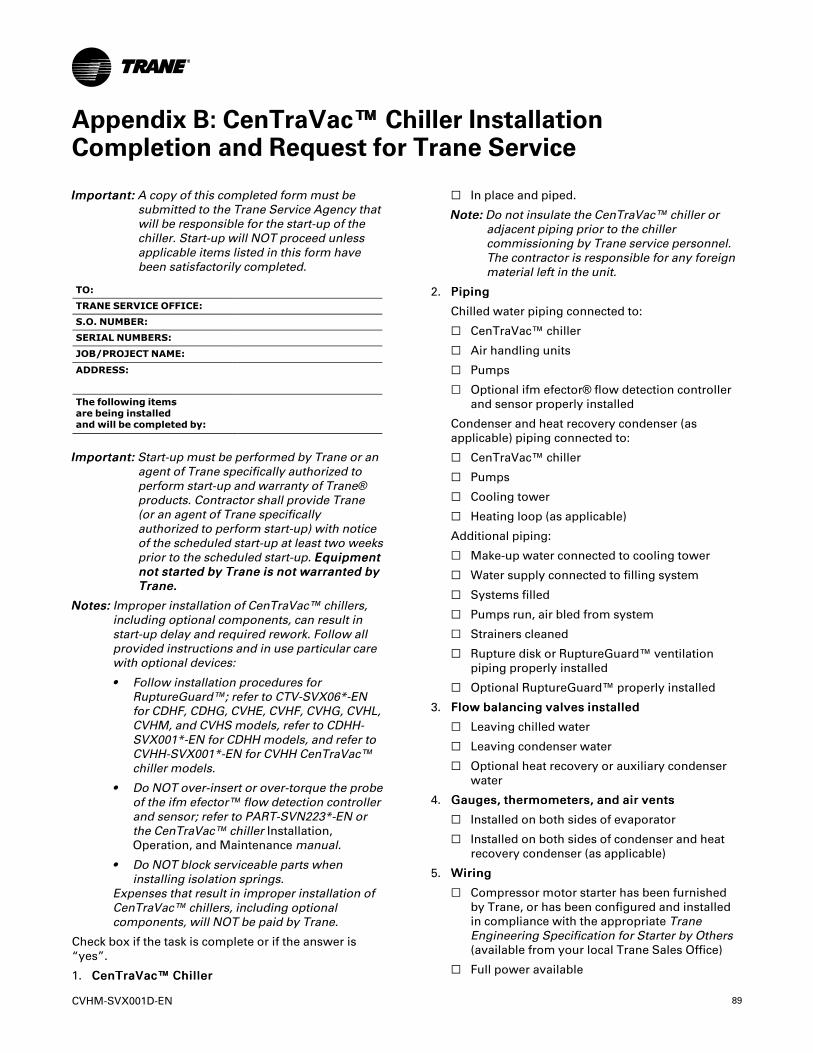
CVHM-SVX001D-EN 89
Appendix B: CenTraVac™™ Chiller InstallationCompletion and Request for Trane Service
IImmppoorrttaanntt:: A copy of this completed form must besubmitted to the Trane Service Agency thatwill be responsible for the start-up of thechiller. Start-up will NOT proceed unlessapplicable items listed in this form havebeen satisfactorily completed.
TO:TRANE SERVICE OFFICE:S.O. NUMBER:SERIAL NUMBERS:
JOB/PROJECT NAME:
ADDRESS:
The following itemsare being installedand will be completed by:
IImmppoorrttaanntt:: Start-up must be performed by Trane or anagent of Trane specifically authorized toperform start-up and warranty of Trane®products. Contractor shall provide Trane(or an agent of Trane specificallyauthorized to perform start-up) with noticeof the scheduled start-up at least two weeksprior to the scheduled start-up. EEqquuiippmmeennttnnoott ssttaarrtteedd bbyy TTrraannee iiss nnoott wwaarrrraanntteedd bbyyTTrraannee..
NNootteess:: Improper installation of CenTraVac™ chillers,including optional components, can result instart-up delay and required rework. Follow allprovided instructions and in use particular carewith optional devices:
• Follow installation procedures forRuptureGuard™; refer to CTV-SVX06*-ENfor CDHF, CDHG, CVHE, CVHF, CVHG, CVHL,CVHM, and CVHS models, refer to CDHH-SVX001*-EN for CDHH models, and refer toCVHH-SVX001*-EN for CVHH CenTraVac™chiller models.
• Do NOT over-insert or over-torque the probeof the ifm efector™ flow detection controllerand sensor; refer to PART-SVN223*-EN orthe CenTraVac™ chiller Installation,Operation, and Maintenancemanual.
• Do NOT block serviceable parts wheninstalling isolation springs.
Expenses that result in improper installation ofCenTraVac™ chillers, including optionalcomponents, will NOT be paid by Trane.
Check box if the task is complete or if the answer is“yes”.
1. CCeennTTrraaVVaacc™™ CChhiilllleerr
☐ In place and piped.
NNoottee:: Do not insulate the CenTraVac™ chiller oradjacent piping prior to the chillercommissioning by Trane service personnel.The contractor is responsible for any foreignmaterial left in the unit.
2. PPiippiinngg
Chilled water piping connected to:
☐ CenTraVac™ chiller
☐ Air handling units
☐ Pumps
☐ Optional ifm efector® flow detection controllerand sensor properly installed
Condenser and heat recovery condenser (asapplicable) piping connected to:
☐ CenTraVac™ chiller
☐ Pumps
☐ Cooling tower
☐ Heating loop (as applicable)
Additional piping:
☐ Make-up water connected to cooling tower
☐ Water supply connected to filling system
☐ Systems filled
☐ Pumps run, air bled from system
☐ Strainers cleaned
☐ Rupture disk or RuptureGuard™ ventilationpiping properly installed
☐ Optional RuptureGuard™ properly installed
3. FFllooww bbaallaanncciinngg vvaallvveess iinnssttaalllleedd
☐ Leaving chilled water
☐ Leaving condenser water
☐ Optional heat recovery or auxiliary condenserwater
4. GGaauuggeess,, tthheerrmmoommeetteerrss,, aanndd aaiirr vveennttss
☐ Installed on both sides of evaporator
☐ Installed on both sides of condenser and heatrecovery condenser (as applicable)
5. WWiirriinngg
☐ Compressor motor starter has been furnishedby Trane, or has been configured and installedin compliance with the appropriate TraneEngineering Specification for Starter by Others(available from your local Trane Sales Office)
☐ Full power available
90 CVHM-SVX001D-EN
☐ Interconnecting wiring, starter to panel (asrequired)
☐ External interlocks (flow switch, pumpsauxiliary, etc.)
☐ Chiller motor connection (remote starters)
NNoottee:: Do not make final remote starter-tocompressor motor connections untilrequested to do so by the Trane servicerepresentative!
☐ Chilled water pump (connected and tested)
☐ Condenser water pump (connected and tested)
☐ Optional ifm efector® flow detection controllerand sensor cable properly installed and securedfor non-stress at probe connector
☐ Cooling tower fan rotation checked
☐ Heat recovery condenser water pump (asapplicable)
☐ 115 Vac power available for service tools
☐ All controls installed and connected
☐ All magnetic starters installed and connected
☐ For CVHS and CVHM chillers, indicate type ofpower distribution grounding:
☐ Solidly Grounded (Center Ground Wye)
-or-
☐ Non-Solidly Grounded (Any Delta, HighImpedance Ground, or Ungrounded Wye)
6. TTeessttiinngg
☐ Dry nitrogen available for pressure testing (fordisassembled units)
☐ Material and equipment available for leaktesting (if necessary)
7. RReeffrriiggeerraanntt
☐ For CDHH and CVHH chillers: Verify suppliedrefrigerant is “Solstice ZD” Refrigeration Gradeby checking certificates provided with tanks.
☐ Refrigerant on job site and in close proximity tochiller
Total amount in cylinders/drums:___________ (specify lb or kg) and fill inspecifics below:
Number of cylinders/drums _____ of size_____ (specify lb or kg)
Number of cylinders/drums _____ of size_____ (specify lb or kg)
NNoottee:: After commissioning is complete, it is theinstaller’s responsibility to transportempty refrigerant containers to an easilyaccessible point of loading to facilitatecontainer return or recycling.
8. SSyysstteemm
☐ Systems can be operated under load conditions.
9. AAvvaaiillaabbiilliittyy
☐ Electrical, control personnel, and contractor’srepresentative are available to evacuate, charge,and test the CenTraVac™ chiller underserviceman’s supervision.
10. EEqquuiippmmeenntt rroooomm
☐ Does the equipment room have a refrigerantmonitor/sensor capable of monitoring andalarming within the allowable exposure level ofthe refrigerant?
☐ Does the installation have properly placed andoperating audible and visual refrigerant alarms?
☐ Does the equipment room have propermechanical ventilation?
☐ If it is required by local code, is a self-containedbreathing apparatus available?
11. OOwwnneerr aawwaarreenneessss
☐ Has the owner been fully instructed on theproper use and handling of refrigerant?
☐ Does the owner have a copy of the MSDS forrefrigerant?
NNoottee:: Additional time required to properly completethe start-up and commissioning, due to anyincompleteness of the installation, will beinvoiced at prevailing rates.
This is to certify that the Trane equipment has beenproperly and completely installed, and that theapplicable items listed above have been satisfactorilycompleted.
Checklist Completed by(Print Name):
SIGNATURE:DATE:
In accordance with your quotation and our purchaseorder number ______________, we therefore require thepresence of Trane service on this site, for the purposeof start-up and commissioning, by ______________(date).
NNoottee:: Minimum of two week advance notification isrequired to allow for scheduling of the chillerstart-up.
ADDITIONAL COMMENTS/INSTRUCTIONS
AAppppeennddiixx BB:: CCeennTTrraaVVaacc™™ CChhiilllleerr IInnssttaallllaattiioonn CCoommpplleettiioonn aanndd RReeqquueesstt ffoorr TTrraannee SSeerrvviiccee
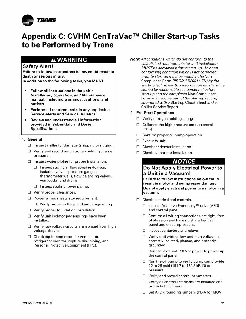
CVHM-SVX001D-EN 91
Appendix C: CVHM CenTraVac™™ Chiller Start-up Tasksto be Performed by Trane
WWAARRNNIINNGGSSaaffeettyy AAlleerrtt!!FFaaiilluurree ttoo ffoollllooww iinnssttrruuccttiioonnss bbeellooww ccoouulldd rreessuulltt iinnddeeaatthh oorr sseerriioouuss iinnjjuurryy..IInn aaddddiittiioonn ttoo tthhee ffoolllloowwiinngg ttaasskkss,, yyoouu MMUUSSTT::
•• FFoollllooww aallll iinnssttrruuccttiioonnss iinn tthhee uunniitt’’ssIInnssttaallllaattiioonn,, OOppeerraattiioonn,, aanndd MMaaiinntteennaanncceemmaannuuaall,, iinncclluuddiinngg wwaarrnniinnggss,, ccaauuttiioonnss,, aannddnnoottiicceess..
•• PPeerrffoorrmm aallll rreeqquuiirreedd ttaasskkss iinn aannyy aapppplliiccaabblleeSSeerrvviiccee AAlleerrttss aanndd SSeerrvviiccee BBuulllleettiinnss..
•• RReevviieeww aanndd uunnddeerrssttaanndd aallll iinnffoorrmmaattiioonnpprroovviiddeedd iinn SSuubbmmiittttaallss aanndd DDeessiiggnnSSppeecciiffiiccaattiioonnss..
1. GGeenneerraall
☐ Inspect chiller for damage (shipping or rigging).
☐ Verify and record unit nitrogen holding chargepressure.
☐ Inspect water piping for proper installation.
☐ Inspect strainers, flow sensing devices,isolation valves, pressure gauges,thermometer wells, flow balancing valves,vent cocks, and drains.
☐ Inspect cooling tower piping.
☐ Verify proper clearances.
☐ Power wiring meets size requirement.
☐ Verify proper voltage and amperage rating.
☐ Verify proper foundation installation.
☐ Verify unit isolator pads/springs have beeninstalled.
☐ Verify low voltage circuits are isolated from highvoltage circuits.
☐ Check equipment room for ventilation,refrigerant monitor, rupture disk piping, andPersonal Protective Equipment (PPE).
NNoottee:: All conditions which do not conform to theestablished requirements for unit installationMUST be corrected prior to start-up. Any non-conforming condition which is not correctedprior to start-up must be noted in the Non-Compliance Form (PROD-ADF001*-EN) by thestart-up technician; this information must also besigned by responsible site personnel beforestart-up and the completed Non-ComplianceForm will become part of the start-up record,submitted with a Start-up Check Sheet and aChiller Service Report.
2. PPrree--SSttaarrtt OOppeerraattiioonnss
☐ Verify nitrogen holding charge.
☐ Calibrate the high pressure cutout control(HPC).
☐ Confirm proper oil pump operation.
☐ Evacuate unit.
☐ Check condenser installation.
☐ Check evaporator installation.
NNOOTTIICCEEDDoo NNoott AAppppllyy EElleeccttrriiccaall PPoowweerr ttooaa UUnniitt iinn aa VVaaccuuuumm!!FFaaiilluurree ttoo ffoollllooww iinnssttrruuccttiioonnss bbeellooww ccoouullddrreessuulltt iinn mmoottoorr aanndd ccoommpprreessssoorr ddaammaaggee..DDoo nnoott aappppllyy eelleeccttrriiccaall ppoowweerr ttoo aa mmoottoorr iinn aavvaaccuuuumm..
☐ Check electrical and controls.
☐ Inspect Adaptive Frequency™ drive (AFD)and control panel.
☐ Confirm all wiring connections are tight, freeof abrasion and have no sharp bends inpanel and on compressors.
☐ Inspect contactors and relays.
☐ Verify unit wiring (low and high voltage) iscorrectly isolated, phased, and properlygrounded.
☐ Connect external 120 Vac power to power upthe control panel.
☐ Run the oil pump to verify pump can provide22 to 26 psid (151.7 to 179.3 kPaD) netpressure.
☐ Verify and record control parameters.
☐ Verify all control interlocks are installed andproperly functioning.
☐ Set AFD grounding jumpers (PE-A for MOV
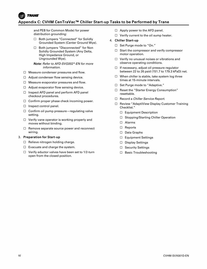
92 CVHM-SVX001D-EN
and PEB for Common Mode) for powerdistribution grounding:
☐ Both jumpers “Connected” for SolidlyGrounded System (Center Ground Wye).
☐ Both jumpers “Disconnected” for NonSolidly Grounded System (Any Delta,High Impedance Ground, orUngrounded Wye).
NNoottee:: Refer to AFD-SVG002*-EN for moreinformation.
☐ Measure condenser pressures and flow.
☐ Adjust condenser flow sensing device.
☐ Measure evaporator pressures and flow.
☐ Adjust evaporator flow sensing device.
☐ Inspect AFD panel and perform AFD panelcheckout procedures.
☐ Confirm proper phase check incoming power.
☐ Inspect control panel.
☐ Confirm oil pump pressure—regulating valvesetting.
☐ Verify vane operator is working properly andmoves without binding.
☐ Remove separate source power and reconnectwiring.
3. PPrreeppaarraattiioonn ffoorr SSttaarrtt--uupp
☐ Relieve nitrogen holding charge.
☐ Evacuate and charge the system.
☐ Verify eductor valves have been set to 1/2-turnopen from the closed position.
☐ Apply power to the AFD panel.
☐ Verify current to the oil sump heater.
4. CChhiilllleerr SSttaarrtt--uupp
☐ Set Purge mode to “On.”
☐ Start the compressor and verify compressormotor operation.
☐ Verify no unusual noises or vibrations andobserve operating conditions.
☐ If necessary, adjust oil pressure regulatorbetween 22 to 26 psid (151.7 to 179.3 kPaD) net.
☐ When chiller is stable, take system log threetimes at 15-minute intervals.
☐ Set Purge mode to “Adaptive.”
☐ Reset the “Starter Energy Consumption”resettable.
☐ Record a Chiller Service Report.
☐ Review “AdaptiView Display Customer TrainingChecklist.”
☐ Equipment Description
☐ Stopping/Starting Chiller Operation
☐ Alarms
☐ Reports
☐ Data Graphs
☐ Equipment Settings
☐ Display Settings
☐ Security Settings
☐ Basic Troubleshooting
AAppppeennddiixx CC:: CCVVHHMM CCeennTTrraaVVaacc™™ CChhiilllleerr SSttaarrtt--uupp TTaasskkss ttoo bbee PPeerrffoorrmmeedd bbyy TTrraannee
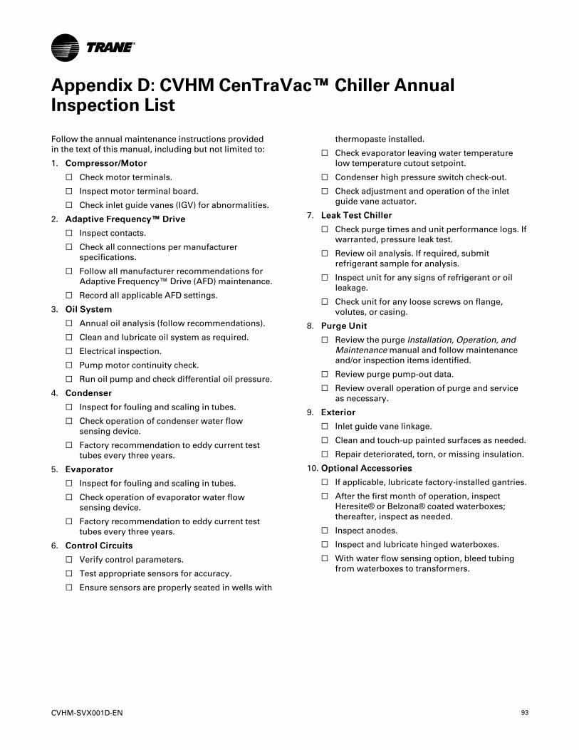
CVHM-SVX001D-EN 93
Appendix D: CVHM CenTraVac™™ Chiller AnnualInspection List
Follow the annual maintenance instructions providedin the text of this manual, including but not limited to:
1. CCoommpprreessssoorr//MMoottoorr
☐ Check motor terminals.
☐ Inspect motor terminal board.
☐ Check inlet guide vanes (IGV) for abnormalities.
2. AAddaappttiivvee FFrreeqquueennccyy™™ DDrriivvee
☐ Inspect contacts.
☐ Check all connections per manufacturerspecifications.
☐ Follow all manufacturer recommendations forAdaptive Frequency™ Drive (AFD) maintenance.
☐ Record all applicable AFD settings.
3. OOiill SSyysstteemm
☐ Annual oil analysis (follow recommendations).
☐ Clean and lubricate oil system as required.
☐ Electrical inspection.
☐ Pump motor continuity check.
☐ Run oil pump and check differential oil pressure.
4. CCoonnddeennsseerr
☐ Inspect for fouling and scaling in tubes.
☐ Check operation of condenser water flowsensing device.
☐ Factory recommendation to eddy current testtubes every three years.
5. EEvvaappoorraattoorr
☐ Inspect for fouling and scaling in tubes.
☐ Check operation of evaporator water flowsensing device.
☐ Factory recommendation to eddy current testtubes every three years.
6. CCoonnttrrooll CCiirrccuuiittss
☐ Verify control parameters.
☐ Test appropriate sensors for accuracy.
☐ Ensure sensors are properly seated in wells with
thermopaste installed.
☐ Check evaporator leaving water temperaturelow temperature cutout setpoint.
☐ Condenser high pressure switch check-out.
☐ Check adjustment and operation of the inletguide vane actuator.
7. LLeeaakk TTeesstt CChhiilllleerr
☐ Check purge times and unit performance logs. Ifwarranted, pressure leak test.
☐ Review oil analysis. If required, submitrefrigerant sample for analysis.
☐ Inspect unit for any signs of refrigerant or oilleakage.
☐ Check unit for any loose screws on flange,volutes, or casing.
8. PPuurrggee UUnniitt
☐ Review the purge Installation, Operation, andMaintenancemanual and follow maintenanceand/or inspection items identified.
☐ Review purge pump-out data.
☐ Review overall operation of purge and serviceas necessary.
9. EExxtteerriioorr
☐ Inlet guide vane linkage.
☐ Clean and touch-up painted surfaces as needed.
☐ Repair deteriorated, torn, or missing insulation.
10. OOppttiioonnaall AAcccceessssoorriieess
☐ If applicable, lubricate factory-installed gantries.
☐ After the first month of operation, inspectHeresite® or Belzona® coated waterboxes;thereafter, inspect as needed.
☐ Inspect anodes.
☐ Inspect and lubricate hinged waterboxes.
☐ With water flow sensing option, bleed tubingfrom waterboxes to transformers.
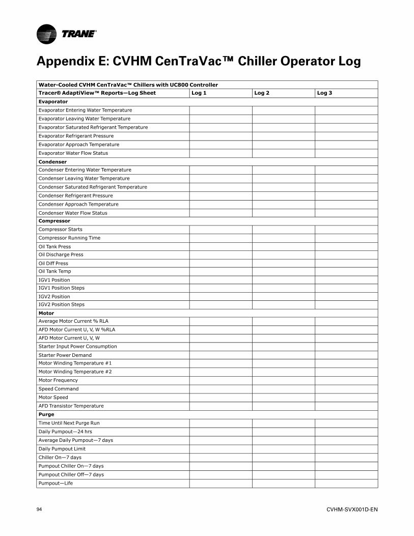
94 CVHM-SVX001D-EN
Appendix E: CVHM CenTraVac™™ Chiller Operator Log
Water-Cooled CVHM CenTraVac™™ Chillers with UC800 ControllerTracer®® AdaptiView™™ Reports—Log Sheet Log 1 Log 2 Log 3Evaporator
Evaporator Entering Water Temperature
Evaporator Leaving Water Temperature
Evaporator Saturated Refrigerant Temperature
Evaporator Refrigerant Pressure
Evaporator Approach Temperature
Evaporator Water Flow Status
CondenserCondenser Entering Water Temperature
Condenser Leaving Water Temperature
Condenser Saturated Refrigerant Temperature
Condenser Refrigerant Pressure
Condenser Approach Temperature
Condenser Water Flow StatusCompressor
Compressor Starts
Compressor Running Time
Oil Tank PressOil Discharge Press
Oil Diff PressOil Tank Temp
IGV1 PositionIGV1 Position Steps
IGV2 PositionIGV2 Position Steps
MotorAverage Motor Current % RLA
AFD Motor Current U, V, W%RLA
AFD Motor Current U, V, W
Starter Input Power Consumption
Starter Power DemandMotor Winding Temperature #1
Motor Winding Temperature #2
Motor Frequency
Speed Command
Motor Speed
AFD Transistor Temperature
Purge
Time Until Next Purge Run
Daily Pumpout—24 hrs
Average Daily Pumpout—7 days
Daily Pumpout Limit
Chiller On—7 days
Pumpout Chiller On—7 days
Pumpout Chiller Off—7 days
Pumpout—Life

CVHM-SVX001D-EN 95
Water-Cooled CVHM CenTraVac™™ Chillers with UC800 ControllerTracer®® AdaptiView™™ Reports—Log Sheet Log 1 Log 2 Log 3
Purge Refrigerant Compressor Suction Temperature
Purge Liquid Temperature
Date:
Technician:Owner:
AAppppeennddiixx EE:: CCVVHHMM CCeennTTrraaVVaacc™™ CChhiilllleerr OOppeerraattoorr LLoogg
Ingersoll Rand (NYSE: IR) advances the quality of life by creating comfortable, sustainable and efficientenvironments. Our people and our family of brands — including Club Car®, Ingersoll Rand®, Thermo King® andTrane® —work together to enhance the quality and comfort of air in homes and buildings; transport and protectfood and perishables; and increase industrial productivity and efficiency. We are a global business committed to aworld of sustainable progress and enduring results.
ingersollrand.com
Ingersoll Rand has a policy of continuous product and product data improvements and reserves the right to change design and specificationswithout notice.We are committed to using environmentally conscious print practices.
CVHM-SVX001D-EN 16 Oct 2019
Supersedes CVHM-SVX001C-EN (August 2019) ©2019 Ingersoll Rand