Embed Size (px)
DESCRIPTION
sim Tutorial
Citation preview
Aircraft
Extended-range, higher gross weight version; develop-ment began January 1985. As of February 20, 2005, 42airlines had ordered 515 767-300ER’s. 502 orders hadbeen filled, with 13 orders unfilled.
Operating Empty Weight 197000 lbs 89545 kgMax Takeoff Weight 408000 lbs 185454 kgMax Zero Fuel Weight 288000 lbs 130909 kgMax Landing Weight 310000 lbs 140909 kgMax Fuel Weight 161740 lbs 73518 kgMax Cruise Altitude 43,100 feetNormal Speed (FL350) M0.80 (530m / 851k)Max Seating Capacity 350Range : 6289m 10121km(Typical city pairs: Los Angeles/Frankfurt)
Power Plant, Controls & FuelTwo high-bypass turbofans in pods, pylon-mounted onthe wing leading-edges. Powered by two General Elec-tric CF6-80C2 engines rated at 61,500 pounds ofthrust per engine. Engine controls include the throttles,fuel cut-off switches, EEC switches, fire handles, and theThrust Rating Panel (TRP). The FMC contains perform-ance information for the engines and co-ordinates withthe autothrottle and TRP to control engine power for de-rated takeoffs as well as VNAV climb, cruise and de-scent. Fuel in one integral tank in each wing , and incentre tank, with total capacity of 91,379 litres (24,140US gallons; 20,100 Imp gallons). Refuelling point inport outer wing.
DimensionsWing span 47.57 m (156 ft 1 in)Length 54.94 m (180 ft 3 in)Fuselage 53.67 m (176 ft 1 in)Height overall 15.85 m (52 ft 0 in)Tailplane span 18.62 m (61 ft 1 in)
Welcome to Level-D’s 767-300ER Flight #001from Vancouver to San Francisco, brought toyou by members of the beta team, and a
couple of CVAer’s. We are not professional pilots: weare flightsimmers, just like you. Some of our technicaladvisors (real world 767 pilots) have read through thisdocument, and they are satisified with the informationwe have provided. They aren’t going to let any of usfly their real 76 just yet, but they haven’t said no to ourrequest for dead-heading for a week... (we wish).
The purpose of this tutorial is to provide CVAers withgeneral guidelines to effectively fly the Level-D 767. Itis not the definitive guide: that document wouldencompass several thousand pages, and enlist theuser to devote thousands of hours of study.
It is important to note that no two airlines operate theiraircraft in the same manner. Each airline adoptsSOP’s (standard operating procedures) for the aircraftin their fleet. While your “airline” may operate withdifferent standards than those set forth, we havechosen to adopt a “mix” of standards to ensure thesafe operation of the LDS767.
This Tutorial includes: Pre-Flight, Flight Deck Prep.,FMC Programming, Engine Start, Taxi, Take-off, InitialClimb & Cruise, Descent, Approach, Landing, Taxi,Shutdown, a Beta-bums Bonus Page, Checklist, FlightPlan, Charts, and the FAQ.
Print this document and complete the sections in chrono-logical order. Save a situation file after each com-pleted section so that you may review any giventutorial section at a later date.
Our flight will utilize the LDS767’s Expanded Checklistincluded with the manual for its structure, and isintended as a step-by-step guide to assist the noviceand intermediate LDS767 pilot.
The Level-D 767 is a complex simulation. It will take youmany hours to master all aspects of the aircraft. Whilethis tutorial serves a useful purpose, we recommendthat you read the manual in its entirety to gain adeeper understanding of the LDS767. Enjoy your flightfrom Vancouver to San Francisco: though CVA’sschedule denotes a CLASS 2 aircraft for this routing,we trust that you will feel a great sense of satisfactionaboard Level-D’s 767 Flight001 Tutorial.
Daryl Shuttleworth & Bill VanCaulart& Members of the LDS767 Beat Team
Fun FactsThe 767 is the favorite airplane on Atlantic routes; it
flies across the Atlantic more frequently than allother jetliners combined.
If GE CF6-80C2B8F engines were attached to atypical automobile (or a 1992 Plymouth Voyager),at takeoff power the car would accelerate fromzero to 60 mph (96.5 kph) in less than half asecond.
There are 3.1 million parts in a 767 provided by morethan 800 suppliers.
There are 117 miles (188 km) of wires in a 767-300ER.
CVA 767-300ERTutorial Flight
Pre-Flight
In this section we will setup the files, program, aircraft, and simulator, so that we are all working with the same“default” settings. Please read and follow these directions carefully. The tutorial is based on these settings.
1. Create a Cold & Dark situation file called “Cold&Dark”.See FAQ included in this document for more informa-tion.
2.Check the CVA website to download the CVA LDS 767.Use the LDS Repaint Manager (on the Desktop) toinstall the livery into FS.
3. Open the LDS 767 Configuration Manager (defaultinstalled to your Desktop) and choose from theseoptions:— Virtual Cockpit Options > No Virtual Cockpit— Basic Aircraft Configuration > Long Haul Flight— Choose “Cargo Load” button and load approx.
48,200 lbs (21,907 KG) of Cargo / Passengers.— Choose “Passenger Load” to return to the main
screen and click on the minus button of the “Pro-pose Fuel” menu to “propose” 35,000 lbs (15,876KG) of fuel for the flight (we will manually load thefuel into the aircraft later, but 35,000 is closeenough to get the trim setting for the flight). SeeFAQ included in this document for more informa-tion.
— Confirm & Note settings for later use in FMC— ZFW approx. 245,200 (111,266 KG)— %MAC 22% / 2.6— Max Gross Weight 280,202 (127,141 KG)
— “Save Settings” & “Exit” the Manager
4. Start Flight Simulator. To maximize the LDS767experience, take the time now to set up the various FS& Level-D menu(s). A registered copy (version 4.66) ofthe FSUIPC module by Pete Dowson is not essential,but it will enhance the flying experience (http://www.schirati.com/dowson.html). From the FlightSimulator start screen, choose:
SETTINGSSounds > Engines 50%
Cockpit 30%Environment 50%Navigation 10%Lessons 80%ATC 80%
International > U.S. System
CREATE A FLIGHTSelected Aircraft > Level-D Simulations
> LDS DXT3 or 32bitSelected Airport > CYVR, Vancouver Intl., Gate 32Fuel & Payload > 35476 lbs (43%, 1%, 43%)
Press Fly Now!
5. The panel should load with the engines running. Now,let’s set the 767 to a Cold & Dark state. From theLEVEL-D menu, choose:
PANEL > Import Panel data from FlightAvailable Flights > Choose “Cold&Dark”
Import > OK
The flight deck should be cold and dark. Not a whis-per. Not a sound. Spooky quiet. Now, onto the nextLEVEL-D menu, choose:
SETTINGS > Realism & Carrier OptionsCarrier options
Standard-style EADIDual cue Flight DirectorClimb Thrust Derate Washout > None
ConfirmX AFDS automatic multi-channelX GPWS altitude calloutsX EADI Displays A/T flagX Airspeed BUGS option
RealismConfirm
X Battery dischargeX Electric load sheddingX Engines damageX Realistic fuel feed
Automatic door openingIRS position driftIRS needs position entryIRS real align duration
X Autoland restrictionsX Failures repaired by ground crewX FMC tunes ILS
Load realism options with flights
On the final LEVEL-D menu, choose:
SETTINGS > PreferencesX A/T inhibits manual throttle
Level-D PanelLevel-D Gauge Sounds > 50%Level-D Voices > 80%
First OfficerX F/O Active Voice: Bill (mook)X F/O handles gearX F/O handles flaps
F/O resets MCPCrew Voices
Captain: Daryl (who else right?)Ground: Dennis, Ian or JohnF/A: Jenny (Bill’s wife)
3
Flight Deck Preparation
Okay, let’s get this bird powered up and ready to rock and roll. We will use the Normal Procedures & Checklist as ourguide for this tutorial, which is written with the “flow” concept. It is available in the Level-D Simulations 767-300Operating Manual. Before we get to the “flow”, our first order of business is to get the power on, and allow theIRU’s to ALIGN. So, open up the OVERHEAD PANEL <SHIFT><5> or “OVHD” button and begin the...
PreFlightBattery Switch ..............................ONStandby Power Selector ..............AUTOAPU GEN switch ...........................Pushed INBus Tie Switches ..........................AUTOUtility Bus Switches .....................ONGEN CONT Switches ....................Pushed INExternal Power .............................Establish
Press ON when AVAIL light illuminatesand
APU ................................................START then ON
You should have power now. Once the APU light turns toRUN, the external power can be safely disconnected.It’s your call, Captain
Level-D> Ground requests > Power Disconnection
Position Light ...............................ONIRS Mode Selectors ......................NAV
Real align time is ten minutes.FMC Initilisation ........................... POSITION
The Cockpit Preparation flow starts with the upper lefthand corner of the overhead panel <SHIFT><5>.Each overhead panel system is checked in an down-ward flow beginning at the top of each overhead panelcolumn. After the overhead is checked, the flightinstruments and AFDS panel are checked from left toright. From the AFDS panel, follow down the EICASscreens to preflight the pedestal systems.
Overhead PreparationYaw Damper Switches .................ON
Check to make sure both switches are ON. Theseswitches are always left ON.
EEC Switches ...............................ONCheck to make sure both switches are ON. Theseswitches are always left ON
Hydraulic Panel ............................CheckPrimary engine pumps switches ON.Primary electric and all demand pump switches OFF.
Overhead Cautions ......................CheckCheck for normal indications (ex. Door lights).
HF Radio .......................................OFFBattery Switch ..............................ONStandby Power Selector ..............AUTOElectrical Panel .............................Check
All electrical switches should be pushed IN. Electricalswitches are only turned OFF for abnormal conditions
APU ................................................As requiredStart the APU if necessary or establish external power.
Cockpit Voice Recorder – TestListen for test tone.
Emergency Light Switch .............ArmedPassenger Oxygen Switch ..........BlankRam Air Turbine Switch ...............BlankIgnition Switch .............................Set
Set 1 for odd days, 2 for even days, and BOTH for coldweather operations.
Engine Start Selectors .................AUTOFuel Jettison Panel ......................OFF
Switches blank and selector OFF.Fuel Panel .....................................Set
Forward and Aft main fuel pumps OFF. Center fuelpumps OFF. Crossfeed switches OFF.
Fuel quantity and balance ...........CheckCheck the proper fuel load and balance:CYVR-KSFO: Fuel 35476 lbs. Left 43%, Center 1%,Right 43%.
Engine and Wing Anti-Ice ............OFFExterior Lights ..............................As required
Position lights should be ON. All others OFF.Cargo Heat ....................................OFFWindow Heat .................................ONHF Radio .......................................OFFPassenger Signs ..........................As required.
Suggest: No Smoking ON Seatbelts OFFPressurization Panel ....................Set
Set landing altitude. Select AUTO 1 for odd days.Select AUTO 2 for even days. Set auto rate at thedetent position.
Equipment Cooling Switch .........AUTOTemperature Control Knobs........As requiredTrim Air Switch .............................ON
This switch is always left ON.Recirc Fan Switches ....................ON
These switches are always left ON.Pack Control Selectors ................As required
If the APU is in use, turn the pack switches to AUTO. Ifexternal air is in use, turn pack switches OFF.
Isolation switches ........................ONLeft and Right switch ON. Center switch guarded ON
Engine Bleed Switches ................ONThese switches are always left ON.
APU Bleed Switch ........................ONStandard : These switches are always left ON.Alernate: APU should be running at least one minute,minimum, before turning the APU Bleed on.
FMC ...............................................ProgramProgram the FMC with route and performance informa-tion.
Okay, time to get to the heart of the matter: crack openthe FMC and let’s get programming. NOTE: Read thefollowing pages carefully. Take your time inputting thedata.
4
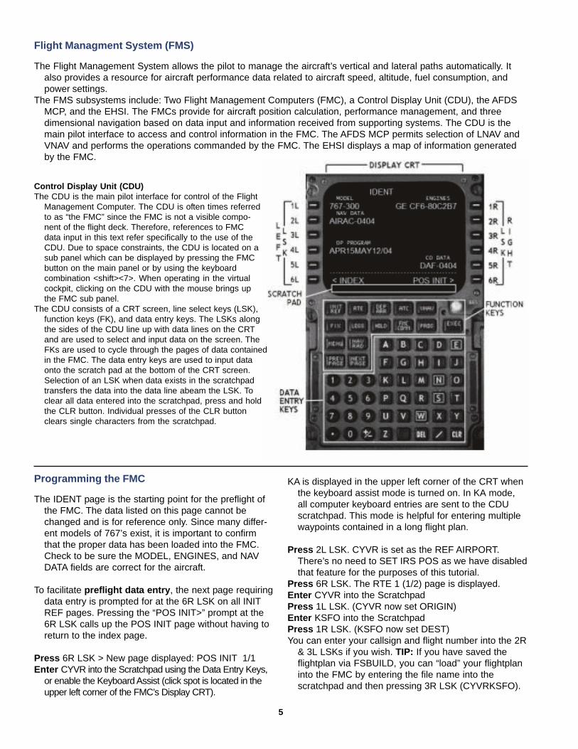
Flight Managment System (FMS)
The Flight Management System allows the pilot to manage the aircraft’s vertical and lateral paths automatically. Italso provides a resource for aircraft performance data related to aircraft speed, altitude, fuel consumption, andpower settings.
The FMS subsystems include: Two Flight Management Computers (FMC), a Control Display Unit (CDU), the AFDSMCP, and the EHSI. The FMCs provide for aircraft position calculation, performance management, and threedimensional navigation based on data input and information received from supporting systems. The CDU is themain pilot interface to access and control information in the FMC. The AFDS MCP permits selection of LNAV andVNAV and performs the operations commanded by the FMC. The EHSI displays a map of information generatedby the FMC.
Control Display Unit (CDU)The CDU is the main pilot interface for control of the Flight
Management Computer. The CDU is often times referredto as “the FMC” since the FMC is not a visible compo-nent of the flight deck. Therefore, references to FMCdata input in this text refer specifically to the use of theCDU. Due to space constraints, the CDU is located on asub panel which can be displayed by pressing the FMCbutton on the main panel or by using the keyboardcombination <shift><7>. When operating in the virtualcockpit, clicking on the CDU with the mouse brings upthe FMC sub panel.
The CDU consists of a CRT screen, line select keys (LSK),function keys (FK), and data entry keys. The LSKs alongthe sides of the CDU line up with data lines on the CRTand are used to select and input data on the screen. TheFKs are used to cycle through the pages of data containedin the FMC. The data entry keys are used to input dataonto the scratch pad at the bottom of the CRT screen.Selection of an LSK when data exists in the scratchpadtransfers the data into the data line abeam the LSK. Toclear all data entered into the scratchpad, press and holdthe CLR button. Individual presses of the CLR buttonclears single characters from the scratchpad.
Programming the FMC
The IDENT page is the starting point for the preflight ofthe FMC. The data listed on this page cannot bechanged and is for reference only. Since many differ-ent models of 767’s exist, it is important to confirmthat the proper data has been loaded into the FMC.Check to be sure the MODEL, ENGINES, and NAVDATA fields are correct for the aircraft.
To facilitate preflight data entry , the next page requiringdata entry is prompted for at the 6R LSK on all INITREF pages. Pressing the “POS INIT>” prompt at the6R LSK calls up the POS INIT page without having toreturn to the index page.
Press 6R LSK > New page displayed: POS INIT 1/1Enter CYVR into the Scratchpad using the Data Entry Keys,
or enable the Keyboard Assist (click spot is located in theupper left corner of the FMC’s Display CRT).
KA is displayed in the upper left corner of the CRT whenthe keyboard assist mode is turned on. In KA mode,all computer keyboard entries are sent to the CDUscratchpad. This mode is helpful for entering multiplewaypoints contained in a long flight plan.
Press 2L LSK. CYVR is set as the REF AIRPORT.There’s no need to SET IRS POS as we have disabledthat feature for the purposes of this tutorial.
Press 6R LSK. The RTE 1 (1/2) page is displayed.Enter CYVR into the ScratchpadPress 1L LSK. (CYVR now set ORIGIN)Enter KSFO into the ScratchpadPress 1R LSK. (KSFO now set DEST)You can enter your callsign and flight number into the 2R
& 3L LSKs if you wish. TIP: If you have saved theflightplan via FSBUILD, you can “load” your flightplaninto the FMC by entering the file name into thescratchpad and then pressing 3R LSK (CYVRKSFO).
5
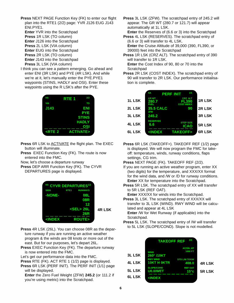
Press NEXT PAGE Function Key (FK) to enter our flightplan into the RTE1 (2/2) page: YVR J126 EUG J143ENI.PYE1.Enter YVR into the ScratchpadPress 1R LSK (TO column)Enter J126 into the ScratchpadPress 2L LSK (VIA column)Enter EUG into the ScratchpadPress 2R LSK (TO column)Enter J143 into the ScratchpadPress 3L LSK (VIA column)
I think you can see a pattern emerging. Go ahead andenter ENI (3R LSK) and PYE (4R LSK). And whilewe’re at it, let’s manually enter the PYE.PYE1waypoints (STINS, HADLY and OSI). Enter thesewaypoints using the R LSK’s after the PYE.
Press 6R LSK to ACTIVATE the flight plan. The EXECbutton will illuminate.
Press EXEC Function Key (FK). The route is nowentered into the FMC.
Now, let’s choose a departure runwayPress DEP ARR Function Key (FK). The CYVR
DEPARTURES page is displayed.
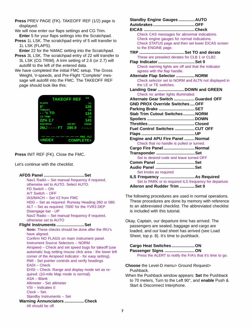
Press 4R LSK (26L). You can choose 08R as the depar-ture runway if you are running an active weatherprogram & the winds are 08 knots or more out of theeast. But for our purposes, let’s depart 26L.
Press EXEC Function Key (FK). The departure runwayis now entered into the FMC.
Let’s get our performance data into the FMC.Press RTE (FK). ACT RTE 1 (1/2) page is displayed.Press 6R LSK (PERF INIT). The PERF INIT (1/1) page
will be displayed.Enter the Zero Fuel Weight (ZFW) 245.2 (or 111.2 ifyou’re using metric) into the Scratchpad.
Press 3L LSK (ZFW). The scratchpad entry of 245.2 willappear. The GR WT (280.7 or 121.7) will appearautomatically at 1L LSK.Enter the Reserves of (6.6 or 3) into the Scratchpad
Press 4L LSK (RESERVES). The scratchpad entry of(6.6 or 3) will transfer to 4L LSK.Enter the Cruise Altitude of 39,000 (390, FL390, or39000) feet into the Scratchpad
Press 1R LSK (CRZ ALT). The scratchpad entry of 390will transfer to 1R LSK.Enter the Cost Index of 90, 80 or 70 into theScratchpad
Press 2R LSK (COST INDEX). The scratchpad entry of90 will transfer to 2R LSK. Our performance initialisa-tion is complete.
Press 6R LSK (TAKEOFF>). TAKEOFF REF (1/2) pageis displayed. We will now program the FMC for take-off: temperature, winds, runway conditions, flapssettings, CG trim.
Press NEXT PAGE (FK). TAKEOFF REF (2/2).If you are running an active weather program, enter XX
(two digits) for the temperature, and XXX/XX formatfor the wind data, and /W or /D for runway conditions.Enter XX for temperature into the Scratchpad.
Press 5R LSK. The scratchpad entry of XX will transferto 5R LSK (REF OAT).Enter XXX/XX for winds into the Scratchpad.
Press 3L LSK. The scratchpad entry of XXX/XX willtransfer to 3L LSK (WIND). RWY WIND will be calcu-lated and appear at 4L LSKEnter /W for Wet Runway (if applicable) into theScratchpad.
Press 5L LSK. The scratchpad entry of /W will transferto 5L LSK (SLOPE/COND). Slope is not modelled.
TAKEOFF REF 2/2
REF OAT
15°c
STD LIM TOGW
408.0
ACCEL HT1000 FT
RWY WIND
10KT H 0KTRSLOPE/COND
U0.0/WET
WIND
260° /10KT
<INDEX— — — — — — — — — —
3L LSK
4L LSK
5L LSK
6L LSK
4R LSK
5R LSK
KA CYVR DEPARTURES1/2
SIDS RTE1 RUNWAYS
-NONE- 08L08R
12<SEL> 26L
26R
<INDEX ROUTE>— — — — — — — — — —
4R LSK
6
KA RTE 1 2/2
VIA TO
J143 ENIPYE
STINSHADLY
OSI<RTE 2 ACTIVATE>
— — — — — — — — — —6.6
STEP SIZE
ICAO— — — — — — — — — —
1L LSK
2L LSK
3L LSK
4L LSK
6L LSK
1R LSK
2R LSK
3R LSK
5R LSK
6R LSK
KA PERF INIT 1/1
GR WT CRZ ALT
280.7 FL390FUEL COST INDEX
35.5 CALC 90ZFW
245.2RESERVES
<INDEX TAKEOFF>
Press PREV PAGE (FK). TAKEOFF REF (1/2) page isdisplayed.
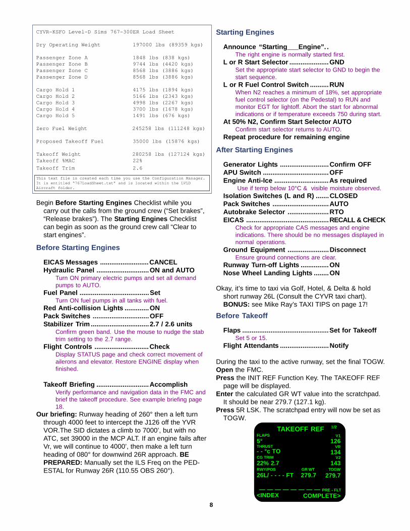
We will now enter our flaps settings and CG Trim.Enter 5 for your flaps settings into the Scratchpad.
Press 1L LSK. The scratchpad entry of 5 will transfer to1L LSK (FLAPS).Enter 22 for the %MAC setting into the Scratchpad.
Press 3L LSK. The scratchpad entry of 22 will transfer to3L LSK (CG TRIM). A trim setting of 2.6 (or 2.7) willautofill to the left of the entered data.
We have completed the initial FMC setup. The GrossWeight, V-speeds, and Pre-Flight “Complete” mes-sage will autofill into the FMC. The TAKEOFF REFpage should look like this:
TAKEOFF REF 1/2
TOGW
- - -. -
V1
126
CG TRIM
22% 2.7RWY/POS
26L/ - - - - FT
THRUST- - °c TO
<INDEX— — — — — — — — PRE - FLT
FLAPS
5°VR
134V2
143GR WT
280.9
COMPLETE>
AFDS Panel ...................................SetNav1 Radio – Set manual frequency if required,otherwise set to AUTO. Select AUTO.FD Switch – ONA/T Switch – OFFIAS/MACH – Set V2 from FMCHDG – Set as required: Runway Heading 260 or 080.ALT – Set as required: 7000’ for the YVR3 DEPDisengage bar - UPNav2 Radio – Set manual frequency if required,otherwise set to AUTO
Flight Instruments ........................SetNote: These checks should be done after the IRU’shave aligned.Confirm NO FLAGS on main instrument panel.Instrument Source Selectors – NORMAirspeed – Check and set speed bugs for takeoff (useautomatic bug setting mouse click area - the lower leftcorner of the Airspeed Indicator - for easy setting).RMI - Set pointer controls and verify headingsEADI – CheckEHSI – Check. Range and display mode set as re-quired. (10-mile Map mode is normal).ASA – BlankAltimeter - Set altimeterVSI – Indicates 0Clock – Set.Standby Instruments – Set
Warning Annunciators .................CheckAll should be off.
Standby Engine Gauges ..............AUTOAutobrakes ....................................OFFEICAS ............................................Check
Check CAS messages for abnormal indications.Check engine gauges for normal indications.Check STATUS page and then set lower EICAS screento the ENGINE page.
TRP .......................................Set TO and derateThese are preselect derates for CLB 1 or CLB2.
Flap Indicator ................................Set 0Check warning lights are off and that the indicatoragrees with the flap handle.
Alternate Flap Selector ................NORMCheck selector set to NORM and ALTN not displayed inthe LE or TE switches.
Landing Gear .......................DOWN and GREENCheck no amber lights illuminated.
Alternate Gear Switch ..................Guarded OFFGND PROX Override Switches ....OFFParking Brake ...............................SETStab Trim Cutout Switches ..........NORMSpoilers .........................................DOWNThrottles ........................................ClosedFuel Control Switches .................CUT OFFFlaps ..............................................UPEngine and APU Fire Panel .........Normal
Check that no handle is pulled or turned.Cargo Fire Panel ...........................NormalTransponder .................................Set
Set to desired code and leave turned OFFComm Panel .................................SetAudio Panel ..................................Set
Set knobs as requiredILS Frequency ..............................As Required
Set to PARK or to required ILS frequency for departureAileron and Rudder Trim .............Set 0
The following procedures are used in normal operations.These procedures are done by memory with referenceto an abbreviated checklist. The abbreviated checklistis included with this tutorial.
Okay, Captain, our departure time has arrived. Thepassengers are seated, baggage and cargo areloaded, and our load sheet has arrived (see LoadSheet, top p. 8). It’s time to pushback.
Cargo Heat Switches ....................ONPassenger Signs ..........................ON
Press the ALERT to notify the F/A’s that it’s time to go.
Choose the Level-D menu> Ground Request>Pushback.
When the Pushback window appears: Set the Pushbackto 70 meters, Turn to the Left 90°, and enable Push &Start & Disconnect Interphone.
Press INIT REF (FK). Close the FMC.
Let’s continue with the checklist.
7
After Starting Engines
Generator Lights ..........................Confirm OFFAPU Switch ...................................OFFEngine Anti-Ice .............................As required
Use if temp below 10°C & visible moisture observed.Isolation Switches (L and R) .......CLOSEDPack Switches ..............................AUTOAutobrake Selector ......................RTOEICAS ............................................ RECALL & CHECK
Check for appropriate CAS messages and engineindications. There should be no messages displayed innormal operations.
Ground Equipment ......................DisconnectEnsure ground connections are clear.
Runway Turn-off Lights ...............ONNose Wheel Landing Lights ........ON
Begin Before Starting Engines Checklist while youcarry out the calls from the ground crew (“Set brakes”,“Release brakes”). The Starting Engines Checklistcan begin as soon as the ground crew call “Clear tostart engines”.
CYVR-KSFO Level-D Sims 767-300ER Load Sheet
Dry Operating Weight 197000 lbs (89359 kgs)
Passenger Zone A 1848 lbs (838 kgs)Passenger Zone B 9744 lbs (4420 kgs)Passenger Zone C 8568 lbs (3886 kgs)Passenger Zone D 8568 lbs (3886 kgs)
Cargo Hold 1 4175 lbs (1894 kgs)Cargo Hold 2 5166 lbs (2343 kgs)Cargo Hold 3 4998 lbs (2267 kgs)Cargo Hold 4 3700 lbs (1678 kgs)Cargo Hold 5 1491 lbs (676 kgs)
Zero Fuel Weight 245258 lbs (111248 kgs)
Proposed Takeoff Fuel 35000 lbs (15876 kgs)
Takeoff Weight 280258 lbs (127124 kgs)Takeoff %MAC 22%
Takeoff Trim 2.6
Before Starting Engines
EICAS Messages ..........................CANCELHydraulic Panel ............................ON and AUTO
Turn ON primary electric pumps and set all demandpumps to AUTO.
Fuel Panel .....................................SetTurn ON fuel pumps in all tanks with fuel.
Red Anti-collision Lights .............ONPack Switches ..............................OFFStabilizer Trim ...............................2.7 / 2.6 units
Confirm green band. Use the mouse to nudge the stabtrim setting to the 2.7 range.
Flight Controls .............................CheckDisplay STATUS page and check correct movement ofailerons and elevator. Restore ENGINE display whenfinished.
Takeoff Briefing ............................AccomplishVerify performance and navigation data in the FMC andbrief the takeoff procedure. See example briefing page18.
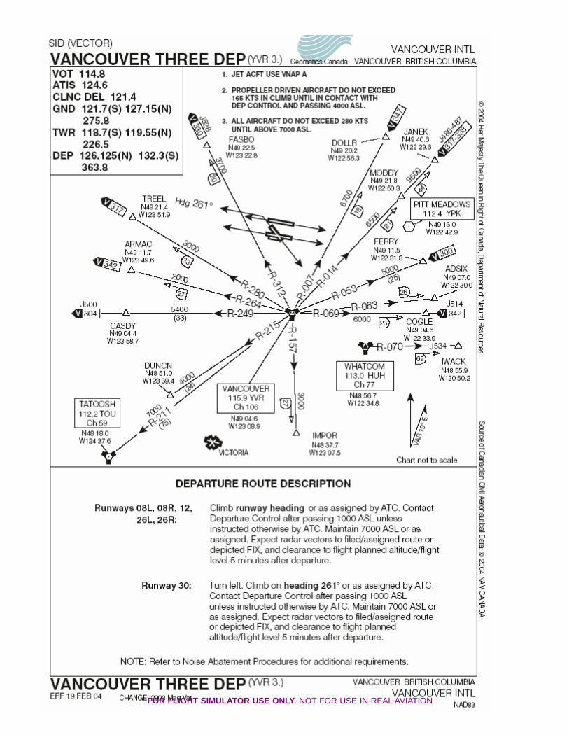
Our briefing: Runway heading of 260° then a left turnthrough 4000 feet to intercept the J126 off the YVRVOR.The SID dictates a climb to 7000’, but with noATC, set 39000 in the MCP ALT. If an engine fails afterVr, we will continue to 4000’, then make a left turnheading of 080° for downwind 26R approach. BEPREPARED: Manually set the ILS Freq on the PED-ESTAL for Runway 26R (110.55 OBS 260°).
Starting Engines
Announce “Starting___Engine”. .The right engine is normally started first.
L or R Start Selector .....................GNDSet the appropriate start selector to GND to begin thestart sequence.
L or R Fuel Control Switch ..........RUNWhen N2 reaches a minimum of 18%, set appropriatefuel control selector (on the Pedestal) to RUN andmonitor EGT for lightoff. Abort the start for abnormalindications or if temperature exceeds 750 during start.
At 50% N2, Confirm Start Selector AUTOConfirm start selector returns to AUTO.
Repeat procedure for remaining engine
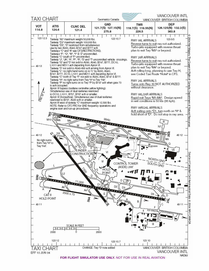
Okay, it’s time to taxi via Golf, Hotel, & Delta & holdshort runway 26L (Consult the CYVR taxi chart).BONUS: see Mike Ray’s TAXI TIPS on page 17!
Before Takeoff
Flaps ..............................................Set for TakeoffSet 5 or 15.
Flight Attendants ..........................Notify
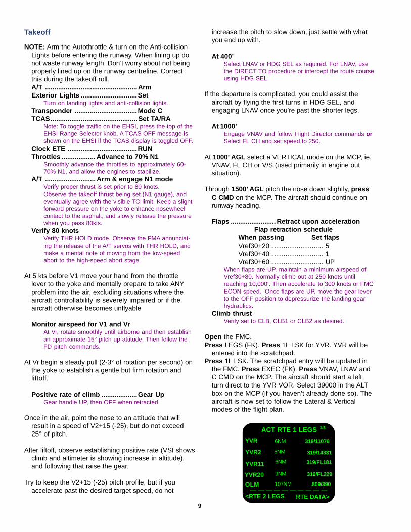
During the taxi to the active runway, set the final TOGW.Open the FMC.Press the INIT REF Function Key. The TAKEOFF REF
page will be displayed.Enter the calculated GR WT value into the scratchpad.
It should be near 279.7 (127.1 kg).Press 5R LSK. The scratchpad entry will now be set as
TOGW.
TAKEOFF REF 1/2
TOGW
279.7
V1
126
CG TRIM
22% 2.7RWY/POS
26L/ - - - - FT
THRUST- - °c TO
<INDEX— — — — — — — — PRE - FLT
FLAPS
5°VR
134V2
143GR WT
279.7
COMPLETE>
8
This text file is created each time you use the Configuration Manager.It is entitled “767LoadSheet.txt” and is located within the LVLDAircraft folder.
Takeoff
NOTE: Arm the Autothrottle & turn on the Anti-collisionLights before entering the runway. When lining up donot waste runway length. Don’t worry about not beingproperly lined up on the runway centreline. Correctthis during the takeoff roll.A/T .................................................ArmExterior Lights ..............................Set
Turn on landing lights and anti-collision lights.Transponder .................................Mode CTCAS..............................................Set TA/RA
Note: To toggle traffic on the EHSI, press the top of theEHSI Range Selector knob. A TCAS OFF message isshown on the EHSI if the TCAS display is toggled OFF.
Clock ETE .....................................RUNThrottles .................. Advance to 70% N1
Smoothly advance the throttles to approximately 60-70% N1, and allow the engines to stabilize.
A/T ........................... Arm & engage N1 modeVerify proper thrust is set prior to 80 knots.Observe the takeoff thrust being set (N1 gauge), andeventually agree with the visible TO limit. Keep a slightforward pressure on the yoke to enhance nosewheelcontact to the asphalt, and slowly release the pressurewhen you pass 80kts.
Verify 80 knotsVerify THR HOLD mode. Observe the FMA annunciat-ing the release of the A/T servos with THR HOLD, andmake a mental note of moving from the low-speedabort to the high-speed abort stage.
At 5 kts before V1 move your hand from the throttlelever to the yoke and mentally prepare to take ANYproblem into the air, excluding situations where theaircraft controllability is severely impaired or if theaircraft otherwise becomes unflyable
Monitor airspeed for V1 and VrAt Vr, rotate smoothly until airborne and then establishan approximate 15° pitch up attitude. Then follow theFD pitch commands.
At Vr begin a steady pull (2-3° of rotation per second) onthe yoke to establish a gentle but firm rotation andliftoff.
Positive rate of climb ...................Gear UpGear handle UP, then OFF when retracted.
Once in the air, point the nose to an attitude that willresult in a speed of V2+15 (-25), but do not exceed25° of pitch.
After liftoff, observe establishing positive rate (VSI showsclimb and altimeter is showing increase in altitude),and following that raise the gear.
Try to keep the V2+15 (-25) pitch profile, but if youaccelerate past the desired target speed, do not
increase the pitch to slow down, just settle with whatyou end up with.
At 400’Select LNAV or HDG SEL as required. For LNAV, usethe DIRECT TO procedure or intercept the route courseusing HDG SEL.
If the departure is complicated, you could assist theaircraft by flying the first turns in HDG SEL, andengaging LNAV once you’re past the shorter legs.
At 1000’Engage VNAV and follow Flight Director commands orSelect FL CH and set speed to 250.
At 1000’ AGL select a VERTICAL mode on the MCP, ie.VNAV, FL CH or V/S (used primarily in engine outsituation).
Through 1500’ AGL pitch the nose down slightly, pressC CMD on the MCP. The aircraft should continue onrunway heading.
Flaps ........................ Retract upon accelerationFlap retraction schedule
When passing Set flapsVref30+20 ............................ 5Vref30+40 ............................ 1Vref30+60 ............................ UP
When flaps are UP, maintain a minimum airspeed ofVref30+80. Normally climb out at 250 knots untilreaching 10,000‘. Then accelerate to 300 knots or FMCECON speed. Once flaps are UP, move the gear leverto the OFF position to depressurize the landing gearhydraulics.
Climb thrustVerify set to CLB, CLB1 or CLB2 as desired.
Open the FMC.Press LEGS (FK). Press 1L LSK for YVR. YVR will be
entered into the scratchpad.Press 1L LSK. The scratchpad entry will be updated in
the FMC. Press EXEC (FK). Press VNAV, LNAV andC CMD on the MCP. The aircraft should start a leftturn direct to the YVR VOR. Select 39000 in the ALTbox on the MCP (if you haven’t already done so). Theaircraft is now set to follow the Lateral & Verticalmodes of the flight plan.
ACT RTE 1 LEGS 1/3
319/11076
YVR11
YVR20
YVR2
<RTE 2 LEGS— — — — — — — — — —
6NM
RTE DATA>
OLM
5NM
6NM
9NM
107NM
319/14381
319/FL181
319/FL229
.809/390
YVR
9
Climb and Cruise
Above 10,000 feetLanding lights ..............................OFFAbove 18,000 feet (or transition altitude)Set altimeters ................................29.92”
The cruise phase on a modern jetliner aircraft is probablythe most neglected phase when it comes to simulatedflying. Many simmers, even experienced ones, tend tothink that during the cruise there’s really nothing leftfor the pilot to do than to just read the newspapers andenjoy the view! While this is partly true (only partly),the cruise phase is just as important as the morehectic departure & arrival phases of flight. During thecruise it is important to prepare for possible troubleand otherwise monitor the aircraft systems, AFDS,FMC, fuel, and routing (as well as reading the paper).Remember, you have to be ahead of the aircraft atALL TIMES.
Some important activities for the cruise phase are:
Make periodic observations on the fuel consumption ofthe aircraft, and compare the figures you see to thenumbers on your flight plan log. This is not done justto see if unpredicted winds are eating your valuablereserve fuel, but to also be on the lookout for possiblefuel leak. Yes, the aircraft can, in theory, experience afuel leak that might go unnoticed, unless a strict fuelamount monitoring policy is implemented.
Always be prepared to change the planned course ofyour flight, in case something goes wrong. There canbe many kinds of unexpected events that will force
you to change your route towards an enroute alter-nate. Some of these include a medical emergency,technical emergency, unexpected requests by ATC.Whatever the reason, you should be able to make alogical and a rather quick decision to ensure the safetyof your aircraft and your passengers.
Even though you have a fully operational TCAS onboardthe aircraft, it doesn’t relieve you from keeping aconstant traffic lookout during the cruise phase. TheTCAS is not an all-encompassing or all-knowingdevice, and you should make it a routine to scan theoutside of the aircraft (while still enjoying the views, ofcourse).
Prepare for the arrival. Get charts ready, adjust theminimum altitudes on your gauges, and consider themany possible obstacles that you could see duringyour approach into destination. Review the arrival andapproach plates; review and program the missedapproach procedure; review the predicted weather andits effect on your arrival. Always remember to keep theFMC in the loop for a better situational awareness.This means that you should make the FMC route looklike your planned arrival. Of course you also have tomake sure you can transition to raw data if needed (ie.Fly on the basic navigational instruments). In short:PREPARE.
NOTE: Look out the window and enjoy the view!
Fuel PanelMonitor balance and turn off Center Fuel Pumps whencenter tank is empty.
After cleaning up the aircraft, there are still some proce-dural things that you need to attend to, before thingswill settle down in the climb. On this tutorial flightwe’re assuming that no climb derates are used, so theclimb will be rather brisk. If conditions permit, duringthe climb out, you can select the Seat Belt sign toAUTO to release the cabin. After passing the transitionaltitude, you should be setting the altimeter to stand-ard setting (29.92 Hg / 1013mb). Through 10,000’ youcan turn the landing lights to OFF.
Be prepared to operate the FMC during the early phasesof the climb to possibly take a new Direct-To to a newwaypoint or manipulate the flight plan in some otherway if the ATC instructions require you to do so. Don’tbe overwhelmed by the many tasks you will be facingduring this time, but instead take one thing at a time,and try to complete everything you set out to do. Don’tworry about the ATC noticing possible little errors youmake in this most heated phase of the flight. Justconcentrate on getting the aircraft safely away fromthe airport within the published boundaries of thedeparture. Above all: FLY THE AIRCRAFT.
10
Coffee & Muffin Corner
I’m almost positive that our LDS767 TechnicalAdvisors: David Barrington (B767 Captain), EricErnst (B767 First Officer), Joe Panford (B767Captain) and Sean Trestrail (B767/A330 Cap-tain) don’t get a lot of time to kick back andread the newspaper at FL390. Sure, those eightto 11 hour flights provide the time to enjoy afew cups of java, perhaps ponder theimponderables, complete a few crosswords...but for today’s short hop into San Francisco theguys barely have time to swallow a “cup ‘o’ joe”,choke back a stale muffin, and read the funnypapers before it’s time to plan the arrival.
So, yes, enjoy the view, a beverage and abrioche, but remember you’ve got a job to do.Stay ahead of the aircraft and plan the descentand approach well before the aircraft reachesthe TOD (top of descent).
The FMC (Part II): Runway 28R
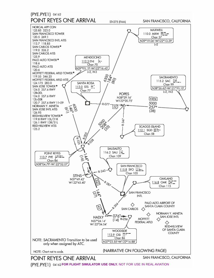
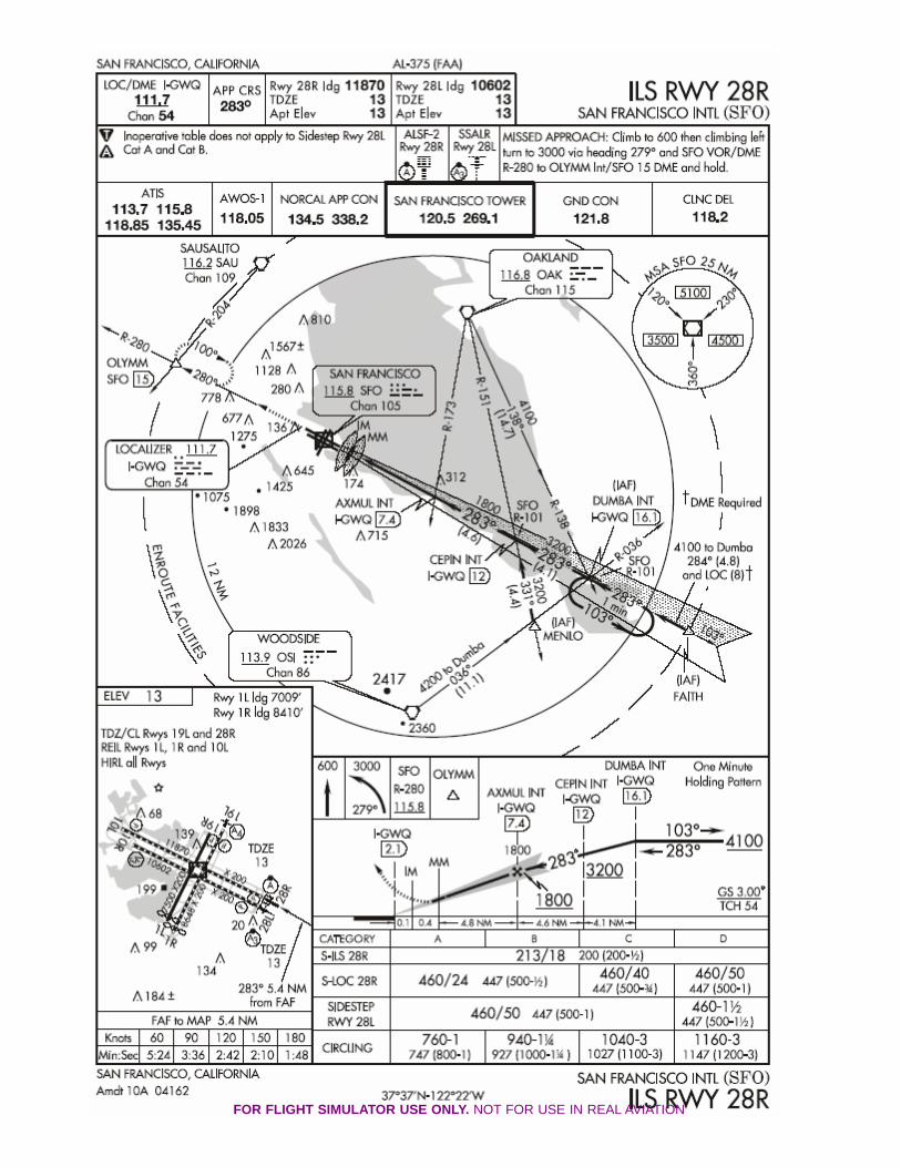
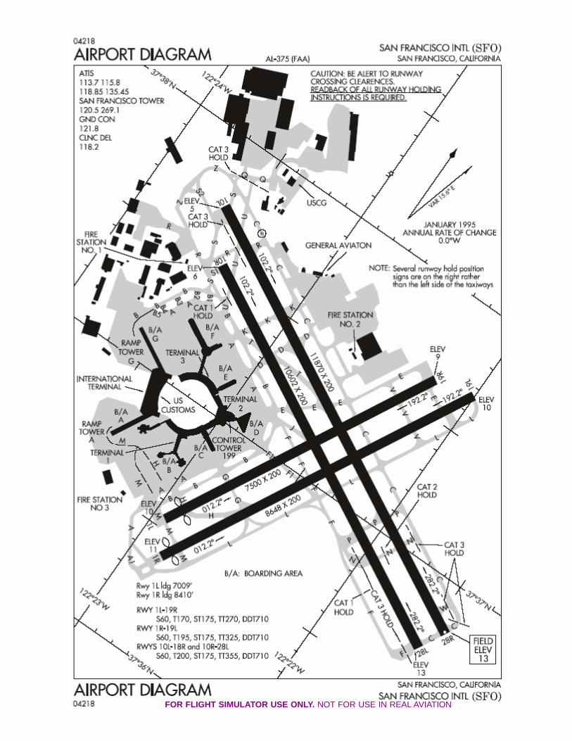
We will land on Runway 28R at San Francisco via thePoint Reyes One Arrival (See PYE.PYE1 Chart). Ifyou are using an active weather program and thewinds are above 07kts, the 28’s may not be appropri-ate. If you’re comfortable planning a different arrivalrunway, go right ahead: for the purposes of this tuto-rial, we will be planning 28R (See ILS RWY 28RChart).
KA DEP/ARR INDEXRTE 1 (ACT)
<DEP CYVR ARR>KSFO ARR>
- - - - - - - - - - -RTE 1 (ACT) - - - - - - - - -
- - - - - - - - - - - - - - - - - - - - - - - - - - - - -
DEP OTHER ARR<--- --->
Press 6L LSK (INDEX). DEP/ARR INDEX page displays.Press 3R LSK (KSFO ARR). KSFO ARRIVALS (1/2)
page will be displayed.Press NEXT PAGE (FK).Press 4R LSK (28R). The runway will be selected, and a
runway extension option will be displayed.Enter the number 12 into the scratchpad.Press 3R LSK to enter the scratchpad entry to RWY
EXT.Press EXEC (FK) to execute the arrival runway. Now
that our arrival runway is set, we need to close adiscontinuity that has occurred in our route.
Press LEGS (FK). ACT RTE1 LEGS (1/3) page will bedisplayed.
Press NEXT PAGE (FK) until runway extension waypoint(RX28R) is visible on the ACT RTE1 LEGS page.
Press the appropriate LSK to place RX28R into thescratchpad.
Press the appropriate LSK to close the discontinuity(The discontinuity will appear as 5 empty squares).
Press EXEC Function Key.
We have completed the setup of the arrival runway. Ifwe were online on VATSIM or another online network,there is a very good likelihood that our arrival wouldbe altered (ATC may dictate crossing & speed restric-tions, or provide vectors off our planned arrival routealtogether). In such circumstances, it is best to have apen & paper handy to write down all clearances. TheFMC can be used to control crossing altitudes andspeed restraints, but don’t be afraid to set the altitudein the MCP ALT and use FLCH to descend. HDG SELcan be used if ATC provides vectors.
PROGRESS 1/2
TO STEP CLIMB
NONE
FUEL
25.3
DEST
KSFOECON SPD
.809
NEXTEUG
< POS REPORT— — — — — — — — — —
TO
UBG
23.9
16.1
POS REF >
ETADTG10 2315z
83 2324z
527 0030z
During the cruise, always monitor the progress of yourflight. Open the FMC.
Press PROG (FK). PROGRESS (1/2) page will bedisplayed. Note the estimated fuel for your destina-tion. Compare those figures to the flight plan.
Press NEXT PAGE (FK). PROGRESS (2/2) page will bedisplayed. Note the information displayed and com-pare those figures to your flight plan. Make notes onyour flight plan for fuel burn, winds aloft, and check tomake sure that you will arrive with fuel to spare:nothing worse than heading to an alternate due toweather and not having the requisite fuel to get there.That’s a big Oooops. Just ask the Gimli Glider guyshow much fun that is.
Continue to monitor the aircraft systems. Examine theinformation the various FMC pages offer.
Let’s look at the VNAV pages...
PROGRESS 2/2
RIGHT
R 6.2
X/WIND
R 28KT
TAS
463KTLEFT
L 6.1
XTRK ERRORR0.0 NM
T/WIND
15KT
-59°C
WIND307°/31
SAT
FUEL USED
CALCULATED
23.1TOTALIZER
23.6FUEL QTY
12.3
KSFO ARRIVALS 2/2
RWY EXT
RUNWAYS
<SEL> 28R
<INDEX— — — — — — — — — —
12.0 NM
ROUTE>
11
Press VNAV (FK). The ACT ECON CRZ (2/3) page willbe displayed. On this page, you can view your com-manded flight level, cruise speed, true airspeed, stepclimb format (in this instance ICAO), step climbinformation, destination estimated time of arrival andfuel, and the optimum and maximum calculated flightlevels. You can manually change your flight level,cruise speed, and step climb format (try entering 2000at 4L LSK), as well as access FMC sub pages. Consultthe manual for more information about the sub pages.
ACT ECON CRZ 2/3
STEP TO
430
TAS
463KTSTEPICAO
ECON SPD.810
CRZ ALT
FL390
0030z/16.1KSFO ETA/FUEL
OPT
LRC>
<ECON
FL384 FL428
NONE
MAX
ENG OUT>— — — — — — — — — —
ACT ECON DES 3/3
AT 28R
0013
SPD TRANS
240/10000SPD RESTR
--- / -----
ECON SPD.810/311
E/D AT
RW28R
DES NOW>
— — — — — — — — — —
Press NEXT PAGE (FK). The ACT ECON DES (3/3)page will be displayed. On this page, you can viewyour destination runway, the runway altitude, thespeed for the descent, the speed transition altitude.You can manually input a speed restriction: Enter 240/10000 into the scratchpad, and press 4L LSK to setthe Speed Restriction. The SPD TRANS will beremoved and the SPD RESTRC will be set.
The DES NOW> at 6R LSK will enable an immediatedescent to the commanded MCP altitude. This is ahandy feature if ATC needs your aircraft at a loweraltitude. FUTURE TIP: Set a lower altitude on theMCP. Press 6R (DES NOW>) and the EXEC (FK) willilluminate. Press EXEC. The aircraft will begin animmediate descent to the MCP commanded altitude.
Right, it’s time to get ready for the descent and arrivalinto San Francisky (For Second City TV fans: “Didjadrive or didja flew?”).
We need to check that our route is correct, so let’s verifythat we’ve set up the FMC correctly.
Rotate the Display control on the EHSI panel from MAPto PLAN. PLAN MODE will display a true north ori-ented map of the current FMC route on the EHSI. TheFMC LEGS page displays <STEP> to cycle throughand display each waypoint in the route.
Press LEGS (FK) on the FMC.Rotate the Range Control (EHSI panel) to 40nm.Press 6R LSK <STEP> and verify that the waypoints for
our arrival are contiguous, and as planned. The EHSIwill display the routing as you press on the 6R LSK<STEP>. Check and verify the route.
FMC Workout (Part III): The Arrival
There are no crossing speeds or altitudes on thePYE.PYE1, but OAK ARTCC will usually commandaircraft to cross STINS waypoint at 250 knots and11000. So, let’s input some crossing restrictions, andadd a waypoint for the intercept.
Press LEGS (FK). The ACT RTE 1 LEGS (1/2) page willbe displayed.
Enter 250/11000 into the Scratchpad.Press R LSK adjacent to the STINS waypoint.Enter 7000 into the Scratchpad.Press R LSK adjacent to the HADLY waypoint.Enter MENLO into the Scratchpad.Press L LSK below the OSI waypoint.A discontinuity will appear. To close the disco: Press
the L LSK next to RX28R. Press the L LSK next to thediscontinuity. The discontinuity will be closed.
Press EXEC (FK).Rotate the Display control on the EHSI panel to MAP
from PLAN. You can leave the EHSI Range Control at40nm or zoom out to 160 (depending on where youare in your cruise).
NOTE: Stay ahead of the aircraft. For this tutorial weare planning our arrival & runway BEFORE the de-scent. If you fly online, be prepared to change any andall of this information during the descent phase.Regardless, take the time to plan ahead. If you can,do it now, before the descent.
12
Planning the MAP (Missed Approach)
You must program the MISSED APPROACH for eachand every arrival runway. When your aircraft is de-scending on the ILS at 160 knots and another aircraftenters the active runway, you will be glad that youplanned a missed approach. See Go Around Proce-dure page 18.
Review the ILS28R chart included: the MAP is OLYMMat 3000’ and hold on the 280° radial, right turns.
Press the LEGS (FK). The ACT RTE 1 LEGS (1/1) pagewill be displayed. Press NEXT PAGE (FK) untilRW28R appears.
Enter OLYMM into the scratchpad.Press L LSK below RW28R. OLYMM will be entered into
the FMC. The EXEC (FK) will light.Enter 3000 into the scratchpad.Press the R LSK adjacent to the OLYMM waypoint.Press EXEC (FK) to execute the missed approach.
Let’s confirm and review our amended routing fromPLAN MODE.
Press LEGS (FK). Press NEXT PAGE (FK) until theACT RTE 1 LEGS page displays the last page of theroute.
Rotate the Display control on the EHSI panel from MAPto PLAN.
Rotate the Range Control (EHSI panel) to 20nm.Press 6R LSK <STEP> and verify that the waypoints for
our amended arrival are contiguous, and as planned.Check the route on the EHSI. Verify the route. Makechanges if there are any errors.
Let’s program the HOLD at OLYMM.
Press HOLD (FK). An entry box will appear at 6L LSK.Press 5L LSK (OLYMM). OLYMM will be entered into the
scratchpad.Press 6L LSK (entry box). OLYMM will be transferred
from the scratchpad to the entry box. The MOD RTE 1HOLD (1/1) page will be displayed.
Enter 280 into the scratchpad.Press 3L LSK. 280 will be entered into the INBD CRS/
DIR column.Press EXEC (FK).
The aircraft be should nearing the TOD (top of de-scent)... so without further adieu, let’s get serious anddrop this aircraft into San Francisco where we canenjoy some of the sights and sounds of the Bay area.
BTW, the company just sent you your next flight plan:KSFO SFO8 RBL J1 SEA PAE ACORD7 CYVR. EnjoyFrisco, baby: you have one hour to turn the aircraftaround as Flight #002, San Francisco to Vancouver.
13
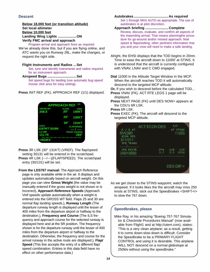
Press 3R LSK (30° 131KT) (VREF). The flap/speedsetting 30131 will be entered in the scratchpad.
Press 4R LSK (---/---)(FLAP/SPEED). The scratchpadentry (30/131) will be set.
APPROACH REF 1/1
FLAP/SPEED
--- / -----
VREF
140KT
KSFO11879FT 3618MILS 28R
111.70
<INDEX— — — — — — — — — —
GROSS WT
268.8
135KT
131KT
FLAPS20°
25°
30°
FRONT COURSE283°
From the LDS767 manual: The Approach Referencepage is only available while in the air. It displays andupdates automatically based on aircraft weight. On thispage you can view Gross Weight (the value may bemanually entered if the gross weight is not shown or isincorrect), Approach Reference Speeds (ApproachVref speeds update automatically when a weight isentered into the GROSS WT field. Flaps 25 and 30 arenormal flap landing speeds.), Runway Length (Thedeparture runway length is displayed until the lesser of400 miles from the departure airport or halfway to thedestination.), Frequency and Course (The ILS fre-quency and approach course for the selected runway isdisplayed here and at the 5R position. The frequencyshown is for the departure runway until the lesser of 400miles from the departure airport or halfway to thedestination. Otherwise, the frequency and course for thearrival runway in the active route are displayed.), Flap/Speed (This line accepts the entry of a different flap/speed combination. Entries in this data field have noeffect on other performance data.)
Press INIT REF (FK). APPROACH REF (1/1) displayed.
Descent
Below 18,000 feet (or transition altitude)Set local altimeterBelow 10,000 feetLanding Wing Lights ...................ONVerify FMC arrival and approach
Program arrival and approach fixes as required.We’ve already done this, but if you are flying online, and
ATC wants you on Runway 28L, make the changes, orrequest the right side.
Flight Instruments and Radios ...SetSet, tune and identify instruments and radios requiredfor an instrument approach.
Airspeed Bugs ..............................SetSet speed bugs for landing (use automatic bug speedmouse click area for easy setting).
Autobrakes ....................................As requiredSet 1 through MAX AUTO as appropriate. The use ofautobrakes is at pilot discretion.
Approach briefing ........................CompleteReview, discuss, evaluate, and confirm all aspects ofthe impending arrival. That means planningthe proce-dure for go-around and/or missed approach; finalspeed & flaps/setting; other pertinent information thatyou and your crew will need to make a safe landing.
Alright, the EHSI displays that the TOD begins in 20nm.Time to ease the aircraft down to 11000’ at STINS. Itis understood that the aircraft is currently configuredwith VNAV, LNAV and C CMD engaged.
Dial 11000 in the Altitude Target Window in the MCP.When the aircraft reaches TOD it will automaticallydescend to the targeted MCP altitude.
Or, If you wish to descend before the calculated TOD...Press VNAV (FK). ACT RTE LEGS 1 page will be
displayed.Press NEXT PAGE (FK) until DES NOW> appears at
the CDU’s 6R LSK.Press 6R LSK.Press EXEC (FK). The aircraft will descend to the
targeted MCP altitude.
As we get closer to the STINS waypoint, watch theairspeed. If it looks likes the the aircraft may miss 250knots at STINS, stick out the Speedbrakes <SHIFT+/>to slow the 767 down.
14
Speedbrakes, please
Mike Ray, in his amazing “Boeing 757-767 Simula-tor & Checkride Procedures Manual” (now avail-able from Flight1 and at http://utem.com), states:“This is a very clean airplane; as a result, gettingit to come down-slow down is difficult. Considerthe Speedbrake to be a PRIMARY FLIGHTCONTROL and using it is desirable. This airplaneWILL NOT descend on a normal glideslope at250kts without using the speedbrake.”
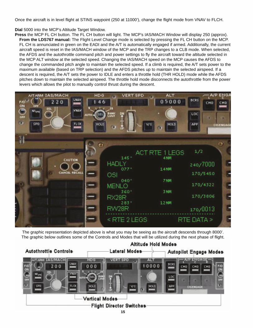
Once the aircraft is in level flight at STINS waypoint (250 at 11000’), change the flight mode from VNAV to FLCH.
Dial 5000 into the MCP’s Altitude Target Window.Press the MCP FL CH button. The FL CH button will light. The MCP’s IAS/MACH Window will display 250 (approx).
From the LDS767 manual: The Flight Level Change mode is selected by pressing the FL CH button on the MCP.FL CH is annunciated in green on the EADI and the A/T is automatically engaged if armed. Additionally, the currentaircraft speed is reset in the IAS/MACH window of the MCP and the TRP changes to a CLB mode. When selected,the AFDS and the autothrottle command pitch and power settings to fly the aircraft toward the altitude selected inthe MCP ALT window at the selected speed. Changing the IAS/MACH speed on the MCP causes the AFDS tochange the commanded pitch angle to maintain the selected speed. If a climb is required, the A/T sets power to themaximum available (based on TRP selection) and the AFDS pitches up to maintain the selected airspeed. If adescent is required, the A/T sets the power to IDLE and enters a throttle hold (THR HOLD) mode while the AFDSpitches down to maintain the selected airspeed. The throttle hold mode disconnects the autothrottle from the powerlevers which allows the pilot to manually control thrust during the descent.
The graphic representation depicted above is what you may be seeing as the aircraft descends through 8000’.The graphic below outlines some of the Controls and Modes that will be utilized during the next phase of flight.
15
Landing
Flaps ........................ Extend during decelerationFlap extension scheduleWhen passing Set flapsVref30+80 Flaps 1Vref30+60 Flaps 5Vref30+40 Flaps 15/20Vref30+20 Flaps 25/30
When flaps are 25/30, the min. speed is Vapproach.Vapproach = Vref30 + wind factorWind factor = ½ steady headwind + gust factorGust factor = gust reported – steady wind
On downwindSet flaps 5 and speed 180.
Glideslope alive or 1500’ RAGear DOWN and Flaps 20.
Speed brakes ................................ARMEDGlideslope capture or 1000’ RA
Set flaps for landing (25 or 30). Landing flaps 30 isnormal. Set speed to Vapproach.
Set Missed Approach altitudeDial altitude into MCP ALT window.
Monitor approach progressAt DA (instrument approach) or 500 feet, announceLANDING. If unable to land, execute a go-around(Procedure page 18).
TouchdownVerify spoiler deployment and decelerate using revers-ers and brakes. Disconnect autopilot and autobrakesprior to turning off the runway.
Allow the aircraft to settle at 220 kts and 5000’. Makesure your Speedbrakes are retracted <SHIFT+/>.
Dial 2500 into the MCP Altitude Target Window.Dial 180 into the MCP Speed Window.Press the MCP FLCH button. The aircraft will begin to
descend to 2500’ while slowing to 180 knots.After the aircraft crosses MENLO,Press the MCP LOC mode button. The AFDS has now
been set to intercept the Localizer freq (111.70) forrunway 28R.
The aircraft should be approximately 12 miles back ofthe threshhold. Once the aircraft starts the turn to the28R inbound course of 283°,
Press the MCP APP button. The AFDS is nowconfigured to follow the ILS on its vertical glideslopepath. Monitor your airspeed, and extend the flaps (ifthe F/O is disabled) as per the Flaps schedule.
Once fully established on the glideslope, reset the MCPALT Window to 3000’ for the MAP.
The Autoland Status of the aircraft is annunciated on theASA at 1500 feet radio height as the multiple autopilotoperation engages. FLARE and ROLLOUT are annun-ciated in white on the EADI when multiple autopilotsare engaged.
Alternatively, (why not, the wx is great!) disconnect theautopilot and hand fly her home.
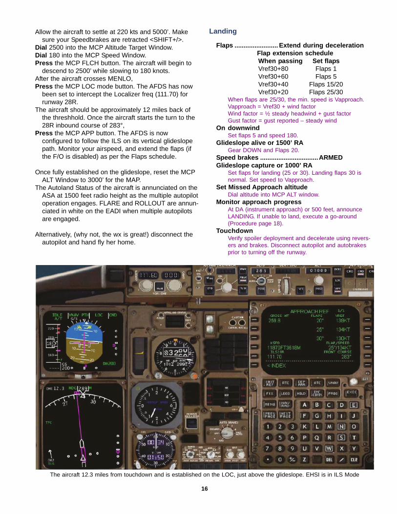
The aircraft 12.3 miles from touchdown and is established on the LOC, just above the glideslope. EHSI is in ILS Mode
16
Complete Shutdown
IRS Mode Selectors ......................OFFEmergency Light Switch .............OFFWindow Heat Switches ................OFFCargo Heat Switches ....................OFFPack Switches ..............................OFFAPU or External Power ................Deselect
Deselect external power or turn off the APU.Standby Power Selector ..............OFFBattery Switch ..............................OFF
After Landing
NOTE: At 80 knots reduce reverse thrust so as to be atidle thrust by 60 knots.
Exterior Lights ..............................As required Runway turn-off lights & white anti-collision lights ON.
Flight Director Switches ..............OFFAutobrakes ....................................OFFSpeed brakes ................................DOWNStab Trim .......................................4 unitsFlaps ..............................................UPTransponder .................................OFFAPU ................................................As required
Start the APU prior to gate arrival if external power isnot available.
Here’s a listing of airline specific gates at KSFO (http://www.flysfo.com/airlines/airlines/index.asp) to dump thepassengers and reload for the return flight to Vancouver.Choose the appropriate gate for your carrier.
Mike Ray’s “Boeing 75-767 Simulator Procedures”offerS this guide to TAXI TIPS...
AIRCRAFT TAXI SPEED GUIDELINES(Use ADI for ground-speed readout)
STRAIGHT AHEAD .......................25 KTSTURNS UP TO 45° ........................25 KTSTURNS GREATER THAN 45° .......10 KTSDURING LANDING ROLL:HIGH SPEED TURNOFF ............... 60 KTS
SNOW & CLUTTER (On Departure)Even though the air may be clear; snow and clutter onthe taxiways and ramp may be ingested and couldcause engine and airframe icing problems. DO NOTLOWER FLAPS. The reasoning here is that some iceor stuff can get lodged in the tracks and cracks andwhen you raise the flaps, they could compress the iceand become jammed or non-functioning.So... GUESS WHAT!IF... you lower the flaps during taxi out on taxiway withice, snow, clutter, etc.THEN... After takeoff when you raise the flaps, youMAY HAVE A FLAP PROBLEM.
Shutdown
Parking Brake ...............................SETAPU or External Power ................Establish
Verify APU is running or request/select external power.Engine Anti-Ice Switches .............OFFIsolation Switches (L and R) .......ON
This permits the APU to supply air to both packs.Fuel Control Switches .................CUT OFFSeat Belt Sign ...............................OFFHydraulic Panel ............................Set
Turn OFF Primary electric pumps and all demandpumps. Primary engine pumps are left ON.
Fuel Pump Switches ....................OFFRed Anti-Collision lights .............OFF
We’re not planning on staying long at KSFO, so there’sno need to do a complete shutdown. But, that check-list has been included for future reference.
We hope you’ve enjoyed Flight 001 aboard LDS’s 767-300ER. It has been a lot of fun (and too many hours atthe keyboard) putting this together. Thanks for flyingwith us. Stay tuned. We look forward to producing indepth tutorials and modules for the next LDS offering:the 757.
Keep the blue side up.
The LDS767 Beta Team
Resources
Vancouver Charts: http://www.czvr.ca/czvr/airports/fields.aspx?icao=cyvrSan Francisco Charts: http://www.zoaatc.com/airports/ksfo.htmlSimRoutes: http://www.SimRoutes.comFSBuild: http://www.fsbuild.comMike Ray 75/76 Sim: http://www.utem.comLevel-D Simulations: http://www.leveldsim.com
17
LDS767 Tutorial Flight 001. Version 1.00. March 15, 2005.
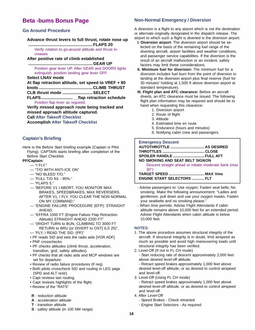
Go Around Procedure
Advance thrust levers to full thrust, rotate nose up.......................................................FLAPS 20
Verify rotation to go-around attitude and thrust in-creases
After positive rate of climb established.......................................................GEAR UP
Position gear lever UP. After GEAR and DOORS lightsextinguish, position landing gear lever OFF.
Select LNAV modeAt flap retraction altitude, set speed to VREF + 80knots ..............................................CLIMB THRUSTCLB thrust mode .......................... SELECTFLAPS........................... __flap retraction schedule
Position flap lever as required.Verify missed approach route being tracked andmissed approach altitude captured.Call After Takeoff ChecklistAccomplish After Takeoff Checklist
18
Beta -bums Bonus Page
Captain’s Briefing
Here is the Before Start briefing example (Captain is PilotFlying). CAPTAIN starts briefing after completion of theBefore Start Checklist.
PF/Captain:— “I FLY.”— “T/O WITH ANTI-ICE ON”— “NO BLEED T/O.”— “FULL T/O N1 - 95%.”— “FLAPS 5.”— “BEFORE V1 I ABORT, YOU MONITOR MAX
BRAKES, SPEEDBRAKES, MAX REVERSERS.AFTER V1, I FLY, YOU CLEAR THE NON NORMALON MY COMMAND.”
— “ENGINE FAILURE PROCEDURE (EFP): STRAIGHTAHEAD.
— “EFFRA 1000 FT (Engine Failure Flap RetractionAltitude) STRAIGHT AHEAD 2200 FT”
— “(RIGHT TURN to BUN, CLIMBING TO 3000 FTRETURN to BRU [or DIVERT to OST] ILS 25)”.
— “FLY, I READ THE SID. (PF)”• PF reads SID and sets the radio aids [VOR ADF].• PNF crosschecks• PF checks altitudes (climb thrust, acceleration,
transition, grid, safety altitudes).• PF checks that all radio aids and MCP windows are
set for departure.• Review of radio failure procedures (if req).• Both pilots crosscheck SID and routing in LEG page
(SPD and ALT restr).• Capt reviews taxi routing.• Capt reviews highlights of the flight.• Review of the “RATS”
R : reduction altitudeA : acceleration altitudeT : transition altitudeS : safety altitude (in 100 NM range)
Non-Normal Emergency / Diversion
A diversion is a flight to any airport which is not the destinationor alternate originally designated in the dispatch release. Theairport to which such a flight is diverted is the diversion airport.
I. Diversion airport : The diversion airport should be se-lected on the basis of the remaining fuel range of thediverting aircraft, airport facilities and weather conditions,and passenger service capabilities. If the diversion is theresult of an aircraft malfunction or an incident, safetyfactors may limit these considerations.
II. Minimum fuel for diversion: The minimum fuel for adiversion includes fuel burn from the point of diversion tolanding at the diversion airport plus final reserve (fuel for30 minutes’ holding at 1,500 ft above diversion airport atstandard temperature).
III. Flight plan and ATC clearance: Before an aircraftdiverts, an ATC clearance must be issued. The followingflight plan information may be required and should be tohand when requesting this clearance:
1. Diversion airport2. Route of flight3. Altitude4. Estimated time en route5. Endurance (hours and minutes)6. Notifying cabin crew and passengers.
Emergency DescentAUTOTHROTTLE ................................ AS DESIREDTHROTTLES ........................................ CLOSESPOILER HANDLE .............................. FULL AFTNO SMOKING AND SEAT BELT SIGNON
Descent straight ahead or initiate moderate bank (max30°)
TARGET SPEED .................................. MAX VmoENGINE START SELECTORS ............ FLT
- Advise passengers to: Use oxygen; Fasten seat belts; Nosmoking. Make the following announcement: “Ladies andgentlemen, pull down and use your oxygen masks. Fastenyour seatbelts and no smoking please.”
- When time permits: Advise Flight Attendants if cabinaltitude remains above 10,000 feet for an extended period.Advise Flight Attendants when cabin altitude is below10,000 feet.
NOTES:1. The above procedure assumes structural integrity of the
aircraft. If structural integrity is in doubt, limit airspeed asmuch as possible and avoid high maneuvering loads untilstructural integrity has been verified.
2. Level-Off (If not in FL CH mode)- Start reducing rate of descent approximately 2,000 feetabove desired level-off altitude.- Retract speed brakes approximately 1,000 feet abovedesired level-off altitude, or as desired to control airspeedand level-off.
3. Level-Off (Using FL CH mode)- Retract speed brakes approximately 1,000 feet abovedesired level-off altitude, or as desired to control airspeedand level-off.
4. After Level-Off- Speed Brakes - Check retracted- Engine Start Selectors - As required
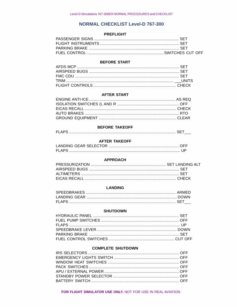
Level-D Simulations 767-300ER NORMAL PROCEDURES and CHECKLIST
NORMAL CHECKLIST Level-D 767-300
PREFLIGHTPASSENGER SIGNS .............................................................................. SETFLIGHT INSTRUMENTS ......................................................................... SETPARKING BRAKE ................................................................................... SETFUEL CONTROL ....................................................................... SWITCHES CUT OFF
BEFORE STARTAFDS MCP .............................................................................................. SETAIRSPEED BUGS ................................................................................... SETFMC CDU ................................................................................................ SETTRIM ................................................................................................... ___UNITSFLIGHT CONTROLS ............................................................................ CHECK
AFTER STARTENGINE ANTI-ICE................................................................................ AS REQISOLATION SWITCHES (L AND R ......................................................... OFFEICAS RECALL .................................................................................... CHECKAUTO BRAKES ....................................................................................... RTOGROUND EQUIPMENT ........................................................................ CLEAR
BEFORE TAKEOFFFLAPS .................................................................................................. SET___
AFTER TAKEOFFLANDING GEAR SELECTOR ................................................................. OFFFLAPS ...................................................................................................... UP
APPROACHPRESSURIZATION ..................................................................... SET LANDING ALTAIRSPEED BUGS ................................................................................... SETALTIMETERS .......................................................................................... SETEICAS RECALL .................................................................................... CHECK
LANDINGSPEEDBRAKES ................................................................................... ARMEDLANDING GEAR ................................................................................... DOWNFLAPS .................................................................................................. SET___
SHUTDOWNHYDRAULIC PANEL ............................................................................... SETFUEL PUMP SWITCHES ........................................................................ OFFFLAPS ...................................................................................................... UPSPEEDBRAKE LEVER.......................................................................... DOWNPARKING BRAKE ................................................................................... SETFUEL CONTROL SWITCHES ............................................................. CUT OFF
COMPLETE SHUTDOWNIRS SELECTORS .................................................................................... OFFEMERGENCY LIGHTS SWITCH ............................................................ OFFWINDOW HEAT SWITCHES .................................................................. OFFPACK SWITCHES ................................................................................... OFFAPU / EXTERNAL POWER..................................................................... OFFSTANDBY POWER SELECTOR ............................................................. OFFBATTERY SWITCH ................................................................................. OFF
FOR FLIGHT SIMULATOR USE ONLY. NOT FOR USE IN REAL AVIATION
FOR FLIGHT SIMULATOR USE ONLY. NOT FOR USE IN REAL AVIATION
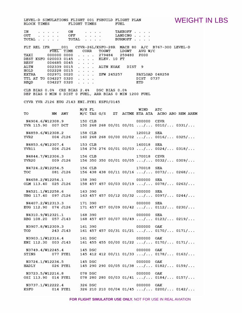
WEIGHT IN LBS
FOR FLIGHT SIMULATOR USE ONLY. NOT FOR USE IN REAL AVIATION
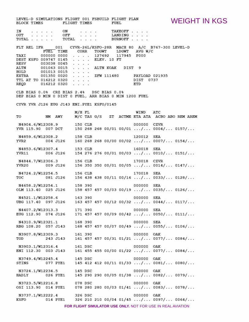
WEIGHT IN KGS
FOR FLIGHT SIMULATOR USE ONLY. NOT FOR USE IN REAL AVIATION
FOR FLIGHT SIMULATOR USE ONLY. NOT FOR USE IN REAL AVIATION
FOR FLIGHT SIMULATOR USE ONLY. NOT FOR USE IN REAL AVIATION
FOR FLIGHT SIMULATOR USE ONLY. NOT FOR USE IN REAL AVIATION
FOR FLIGHT SIMULATOR USE ONLY. NOT FOR USE IN REAL AVIATION
I have Win 98/ME can I use the Level-D Sim 767?No the LDS767 is NOT compatible with windows 98.
What should my Trim rate be set at in the FScontrols assignments window?
The trim rate in the LDS 767 has been configured withcustom gauges to operate as close to reality aspossible to ensure the trim is configured correctlyrepeat rate should be set at 50% for proper operation ofthe Stabilizer Trim.
How do I load a Cold and Dark flight?Load the LDS-767, From the LEVED-D menu selectPANEL—>IMPORT PANEL DATA FROM A FLIGHT,Select the Demo Flight Parked at Seattle, press importand OK.
Can I import FS9 flight plans into the FMC?No the LDS-767 cannot import FS9/GPS flight plans.
Can I use the old Flight plan format from the 2000/2002 version in the new Level-D?
Yes the old Flight Plan format can be used in the LVD-D 767. FP’s built with FSbuild will work as well. SaveThem In your RootFS9/Level-D Simulations/Navdata/Flightplans.
Can I import the older SIDs and STARs from theprevious version of the 767?
No, the LVD767 uses and new XML format for the navdata, the older data cannot be imported into LVD767.Old PIC767 procedures are no longer compatibledue to a new file format that was implemented forbetter performance.
Are there any re-paints for the Level-767 model?Many liveries are available as free downloads fromhttp://www.leveldsim.com/files/repaints/ shortly afterthe release, as well as a paint kit.
How do I turn off morse code sounds when I loadthe panel?
The selectors are on because they are selected on yourdefault flight. On the Pedestal is the Audio controlpanel, click on the VOR, ILS and ADF selectors so thearrow are pointed down and not illuminated. See pg157of the manual for instruction on the Audio Panel.
Why does the flap indicator jump from 0 to flap1,is it broken ?
This is the way it works in real life due to sensorconstruction / operation you will not see the indicationreport mid travel position on flaps 0 to 1, this ismodeled as it is in real life.
Why can’t I tune the ILS in NAV1 on theglareshield anymore?
ILS is now modeled as it is in the real plane. To tunethe ILS use the separate ILS receiver box on thepedestal. You cannot tune ILS frequencies in the realaircraft’s NAV receiver either; it will only accept validVOR frequencies. It can also be tuned automatically bythe FMC by selecting the “FMC tunes ILS” in theRealism & carrier options under the Level-D menu.(Note you must select the arrival rwy in the FMC forthis option to work).
What are all those switches for on the overhead?L C R L R?
Those are the SECAL code selector they are notsimulated in the sim.
I hear a high pitch siren sound when I shut downthe APU?
The tone is from the IRS, as you have disconnected theAC power when shutting down the APU. To cancel thesound, switch the all three IRS’ on the overhead panelfrom NAV to OFF, or restore GRND or APU power.
I switch the APU to start but it doesn’t seem to beturning on?
The APU start time has been modeled to take between1 to 2 mins to start. So please wait as the start time isnow realistic, wait and within two mins the RUNindication will tell you that the APU is available.
When I tune the HF radios on the Overhead I onlyhear static?
HF is not simulated in FS. The static is simulating thestatic heard when no transmission are being made onthe HF frequencies. The only frequencies that do nothave static are 5.000, 10.000 and 15.000. Thesefrequencies broadcast a clock tone. The HF radios areNon functional. To help with realism you can play thereal Atlantic Oceanic during you flight at LiveATC.net.
What is the Airspeed BUGS option? In the Level-Dmenu mean?
This will change the airspeed bugs setup on theAirspeed Indicator after you have programmed theFMC for TO & Landing the two options are (following isfrom the manual)On the ground(for Takeoff): Checked: V1, VR, V2 (MCP bug),Vref30+40, Vref30+80.Un-Checked: V1, V2 (MCP bug), Vref30+20,Vref30+40, Vref30+60, Vref30+80. In flight(for Landing): Checked: Vref30, Vref30+40 Vref30+80.Un-Checked: Vref30, Vref30+20, Vref30+40,Vref30+60, Vref30+80See pages 12 and 65 of the Level-D manual.
Why doesn’t AutoLand arm automatically?It will only arm automatically if you have “AFDSautomatic multi-channel” selected in the Level-D menu“Carrier and realism” setting, If not you have to arm theleft, center and right A/P manually before the AFDSsystem will active for an Autoland.
Where is the load manager located?After the install there should be a “767-300 loadmanager” short cut on your desktop. If it is not therelook in START— > Programs— > Flight1—> Level-Dsimulations menu.
How do I find the CofG for the FMC take-off pageto get my Take off trim setting?
In the load manager there is a section to input theestimated fuel load. Use the + or – buttons to adjust theamount f fuel you have or will have on board. Andbelow it will tell you what your center of Gravity is forinput into the FMC. You can also enter the CG in theFMC Takeoff page. This will provide the takeoff trimsetting.
Frequently Asked Questions
I don’t have any failures set but I get a cargooverheat warning?
When flying out of airports with higher temperaturesthe cargo heat is not needed. So shut off the cargo heatswitches on the overhead.
The strobes lights do not turn on unless theposition lights are on?
This is not a bug. Due to limitations in G-max theposition lights are tied to strobes. The only way to getthe lights to work independently would have been toremove the flexing wings feature.
How do I get my Aerosoft MCP to work with theLVD-767?
First you must ensure you are using the latest firmwareversion 2.2, if not follow the update details carefullyhere www.mcp747.com/ .In the FS9\Level-D Simulations\Level-D SDK\ folderyou will find a file called LVLDSDK.dll you must COPYthis file to your into the Aerosoft’s directory (the direc-tory where 747mcp.exe is). As well as move theAerosoft’s MCP Interface (v2.4b) file 747mcp.exe foundin the FS9\Level-D Simulations\Level-D SDK\ folderand put the EXE in your main Aerosoft install folderoverwriting the original.
I cannot seem to disarm the autobrake with myrudder pedals.
During the beta test some testers was unable to disarmthe autobrakes with their rudder pedals. If you encoun-ter this problem tap your assigned brake button on theyoke/stick or the keyboard. Alternately you can disarmthe brakes by moving the throttles forward and back.There has also been reported issues with FSUIPC v3.45 (shipped with the release) and LDS-767 brakeoperation, if you find this happening download thenewest version of FSUIPC http://www.schiratti.com/dowson.html .
What is the Temp Sel knob for on the TRP (Thrustrating panel)?
The temperature selector allows you to manually setthe De-rated TO temperature. By dialing the knob youwill get the assumed temperature rating displayed onthe EICAS- The assumed temperature selector func-tions only with TO, TO 1 or TO 2 mode displayed. to amax of 25% de-rated thrust.. this operation is used onTake off only.
I get a Black screen when I load up the Level-D767 in full screen mode?
Check to see if your are using any OMEGA drivers,there are known issues’ with Level-D 767 and somebuilds of the omega drivers. Please install the properdrivers direct from Nvidia or ATI.
I cannot select the hidden click spot on the Air-speed indicator to set the “bugs” in the VC.
The click spot to set the Bugs in the VC gauge is notavailable, please set the bug in the 2d and return to theVC and they will be set.
First digit in the transponder will not accept 0 asan entry?
Just enter the non-zero digits, the leading zero will fallinto place.
Why aren’t the MCP mode lights not extinguishingeven if I turn off my flight director?
If the first officer side F/D is still ON, this is what you’llsee. Turn both flight directors off to disable all MCPmodes.
Why is the TAI indication green all the time ?This is correct behaviour for the aircraft modeled.
The FMC will not Accept a higher ZFW amountthat is from the load manager?
Reduce your fuel amount to the proper amount neededfor the flight.
Where do I save FP’s built with FSbuild?Save Them In your RootFS9/Level-D Simulations/Navdata/Flightplans.
EGT, Oil Temperature, and FF Values are blank allblank in the EICAS?
You changed the assigned name of the Level-D folderin the FS9/Aircraft folder. Change the name back toLVLD_B767. Some of the code depends on the exactpath name for the aircraft folder so if you change that itwill not be able to find the flight model file and you willsee the above problems occur.
Quick tips keep coming up even though I uncheckthe show quick tips box?
Open Flight Simulator 9\Level-D Simulations\B767-300and look for the 767-300.ini find the following value“TIP_AT_STARTUP=” and change the value to sayTIP_AT_STARTUP=0 .
How do I start Cold&Dark?Start FS and got to the ‘Create a Flight’ menuSelect an LDS aircraft, location and Fuel/CargoClick ‘Fly now’
Once the aircraft has loaded, select the Level-D menuSelect Panel > ImportSelect the ‘Seattle’ flightSelect Import & then select OK
Why doesn’t the Configuration Manager SET myfuel load when I load the aircraft for a flight?
The proposed amount will NOT be placed into theaircraft.cfg file - you will still have to manually load thefuel once flightsim loads. NOTE: Adjusting the fuel loadwill set a %MAC and CG number for TO trim andallows proper weight/balance calculations. This numbermust be entered into the FMC TAKEOFF page for TRIMsettings to work properly.
My aircraft is very difficult to control. Hand flyingis almost impossible. What’s going on?
Delete and/or rename your FSUIPC.INI file in your FS9/modules folder and let it generate a default one. (DONOT Delete FSUIPC.DLL).