Embed Size (px)
Citation preview
CUTWATER 26/28OWNERS MANUAL
TABLE OF CONTENTS
2
Table Of Contents ........................................................................................................ 2Congratulations ........................................................................................................... 3Safety .......................................................................................................................... 3Symbol Glossary ........................................................................................................... 4Specifications (Subject To Change Without Notice) .................................................................. 5Equipment Location ..................................................................................................... 6
Starboard Fittings .................................................................................................. 6Port Fittings ........................................................................................................... 7Main Cabin Top Deck Components ....................................................................... 8Stern Components ................................................................................................. 9Fuse Location & Values .......................................................................................... 10Main Cabin And Cockpit Lights ............................................................................. 12Battery Compartment ............................................................................................ 13Power Distribution Center ..................................................................................... 14AC Distribution Panel, Rotary Switch & DV Volt Meter ............................................ 15Fuel System, Engine, Generator & Webasto Furnace .............................................. 16Webasto Furnace .................................................................................................. 17Air Conditioning System ........................................................................................ 18Generator ............................................................................................................. 19Solar Panel ............................................................................................................ 20Shore Power .......................................................................................................... 21Closed Engine Cooling System .............................................................................. 22Sea Strainer System ............................................................................................... 23Raw Water Wash Down ......................................................................................... 24Fresh Water Plumbing System ................................................................................ 25Shower Sump ........................................................................................................ 26Bilge Pump System ................................................................................................ 27Waste System ........................................................................................................ 28Mast Set Up And Takedown .................................................................................. 29Cutwater 28 Wiring Schematic (Acc. 1) ................................................................. 30Cutwater 28 Wiring Schematic (Acc. 2) ................................................................. 31Cutwater 28 Wiring Schematic (Acc. 3) ................................................................. 32Cutwater 28 Wiring Schematic (Lighting) .............................................................. 33Cutwater 28 Wiring Schematic (P.D.P.) ................................................................... 34 Cutwater 26 Wiring Schematic (Acc. 1) ................................................................. 35Cutwater 26 Wiring Schematic (Acc. 2) ................................................................. 36Cutwater 26 Wiring Schematic (Acc. 3) ................................................................. 37Cutwater 26 Wiring Schematic (Lighting) .............................................................. 38Cutwater 26 Wiring Schematic (P.D.P.) ................................................................... 39
Working Deck .............................................................................................................. 40Care And Maintenance ................................................................................................ 41
Example Of A Preparation For The Road Checklist .................................................. 41Example Of A Spring Pre-Launch Checklist ............................................................. 42Example Of Winter Storage Checklist .................................................................... 43
Reference Material ....................................................................................................... 44Contacts ...................................................................................................................... 45
3
CONGRATULATIONS
The Cutwater family has a passion for boating. We are committed to continuous process improvement in all areas that affect our customer’s satisfaction with our products and providing great customer service.
SAFETY
Safety is always a concern at Cutwater. Please read all manuals to insure that equip-ment is used in a safe manner. We highly recommend attendance in a Coast Guard approved boating safety course. Such courses are available from the Coast Guard directly or from boating organizations. Owners should have annual inspections to ensure that all safety equipment is current.
STD
OPT
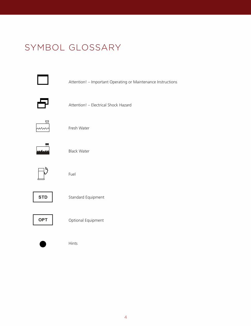
SYMBOL GLOSSARY
4
Attention! – Important Operating or Maintenance Instructions
Attention! – Electrical Shock Hazard
Fresh Water
Black Water
Fuel
Standard Equipment
Optional Equipment
Hints
5
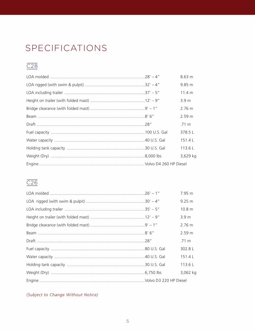
C28
C26
SPECIFICATIONS
(Subject to Change Without Notice)
LOA molded ..................................................................................28’ – 4” 8.63 m
LOA rigged (with swim & pulpit) ....................................................32’ – 4” 9.85 m
LOA including trailer .....................................................................37’ – 5” 11.4 m
Height on trailer (with folded mast) ...............................................12’ – 9” 3.9 m
Bridge clearance (with folded mast) ...............................................9’ – 1” 2.76 m
Beam ............................................................................................8’ 6” 2.59 m
Draft .............................................................................................28” .71 m
Fuel capacity .................................................................................100 U.S. Gal 378.5 L
Water capacity ..............................................................................40 U.S. Gal 151.4 L
Holding tank capacity ...................................................................30 U.S. Gal 113.6 L
Weight (Dry) .................................................................................8,000 lbs 3,629 kg
Engine ...........................................................................................Volvo D4 260 HP Diesel
LOA molded ..................................................................................26’ – 1” 7.95 m
LOA rigged (with swim & pulpit) ...................................................30’ – 4” 9.25 m
LOA including trailer .....................................................................35’ – 5” 10.8 m
Height on trailer (with folded mast) ...............................................12’ – 9” 3.9 m
Bridge clearance (with folded mast) ...............................................9’ – 1” 2.76 m
Beam ............................................................................................8’ 6” 2.59 m
Draft .............................................................................................28” .71 m
Fuel capacity .................................................................................80 U.S. Gal 302.8 L
Water capacity ..............................................................................40 U.S. Gal 151.4 L
Holding tank capacity ...................................................................30 U.S. Gal 113.6 L
Weight (Dry) .................................................................................6,750 lbs 3,062 kg
Engine ...........................................................................................Volvo D3 220 HP Diesel
EQUIPMENT LOCATION
6
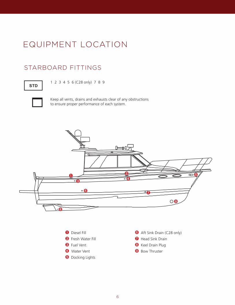
STARBOARD FITTINGS
1 2 3 4 5 6 (C28 only) 7 8 9
Keep all vents, drains and exhausts clear of any obstructions to ensure proper performance of each system.
➋
➌
➎➊➍
➏ ➐
➑
➒
➊ Diesel Fill
➋ Fresh Water Fill
➌ Fuel Vent
➍ Water Vent
➎ Docking Lights
➏ Aft Sink Drain (C28 only)
➐ Head Sink Drain
➑ Keel Drain Plug
➒ Bow Thruster
7
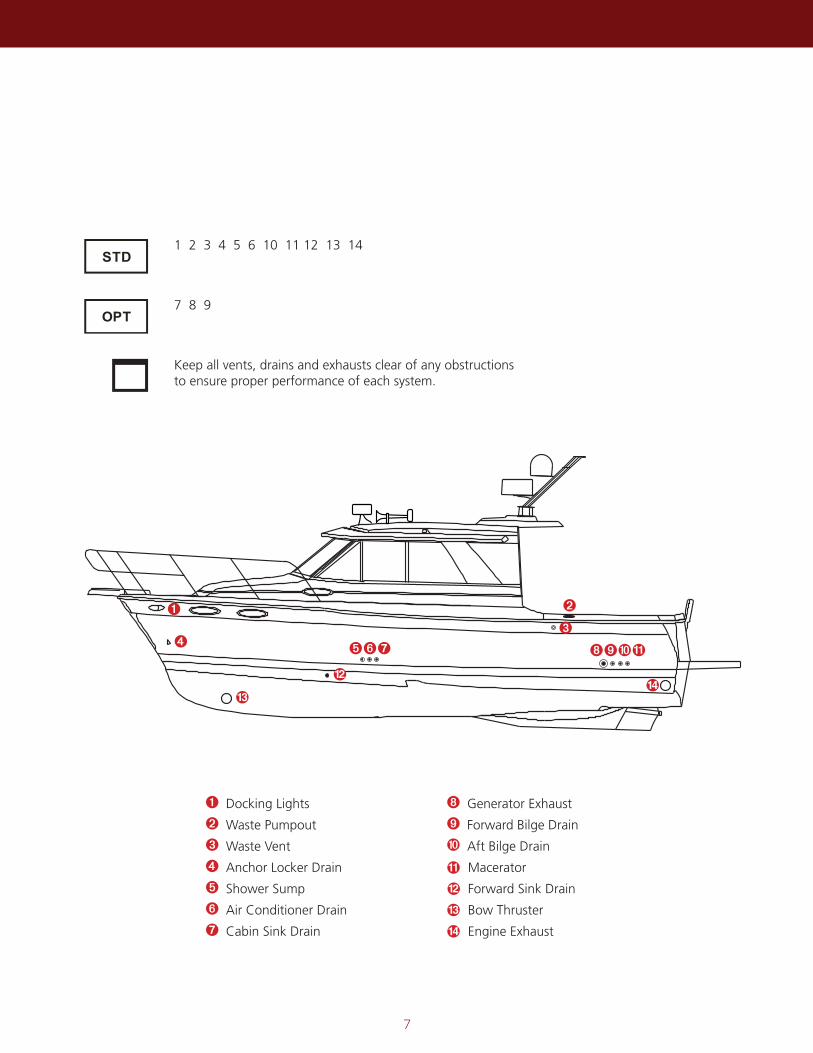
1 2 3 4 5 6 10 11 12 13 14
7 8 9
Keep all vents, drains and exhausts clear of any obstructions to ensure proper performance of each system.
➊
➍
➋
➎➌
➏➐ ➑➒➓11
12
13
➊ Docking Lights
➋ Waste Pumpout
➌ Waste Vent
➍ Anchor Locker Drain
➎ Shower Sump
➏ Air Conditioner Drain
➐ Cabin Sink Drain
➑ Generator Exhaust
➒ Forward Bilge Drain
➓ Aft Bilge Drain
Macerator
Forward Sink Drain
Bow Thruster
Engine Exhaust
11
12
13
14
14
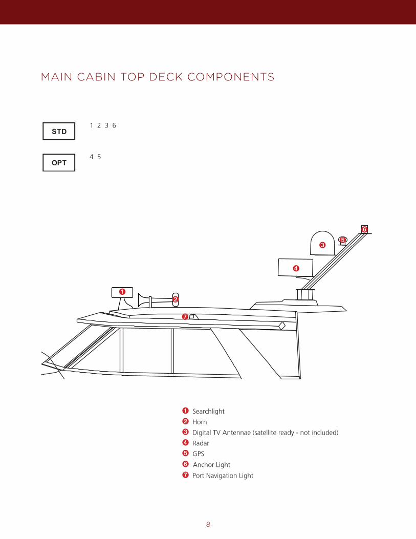
MAIN CABIN TOP DECK COMPONENTS
8
1 2 3 6
4 5
➊ Searchlight
➋ Horn
➌ Digital TV Antennae (satellite ready - not included)
➍ Radar
➎ GPS
➏ Anchor Light
➐ Port Navigation Light
➋
➌➎
➏
➊
➍
➐
9
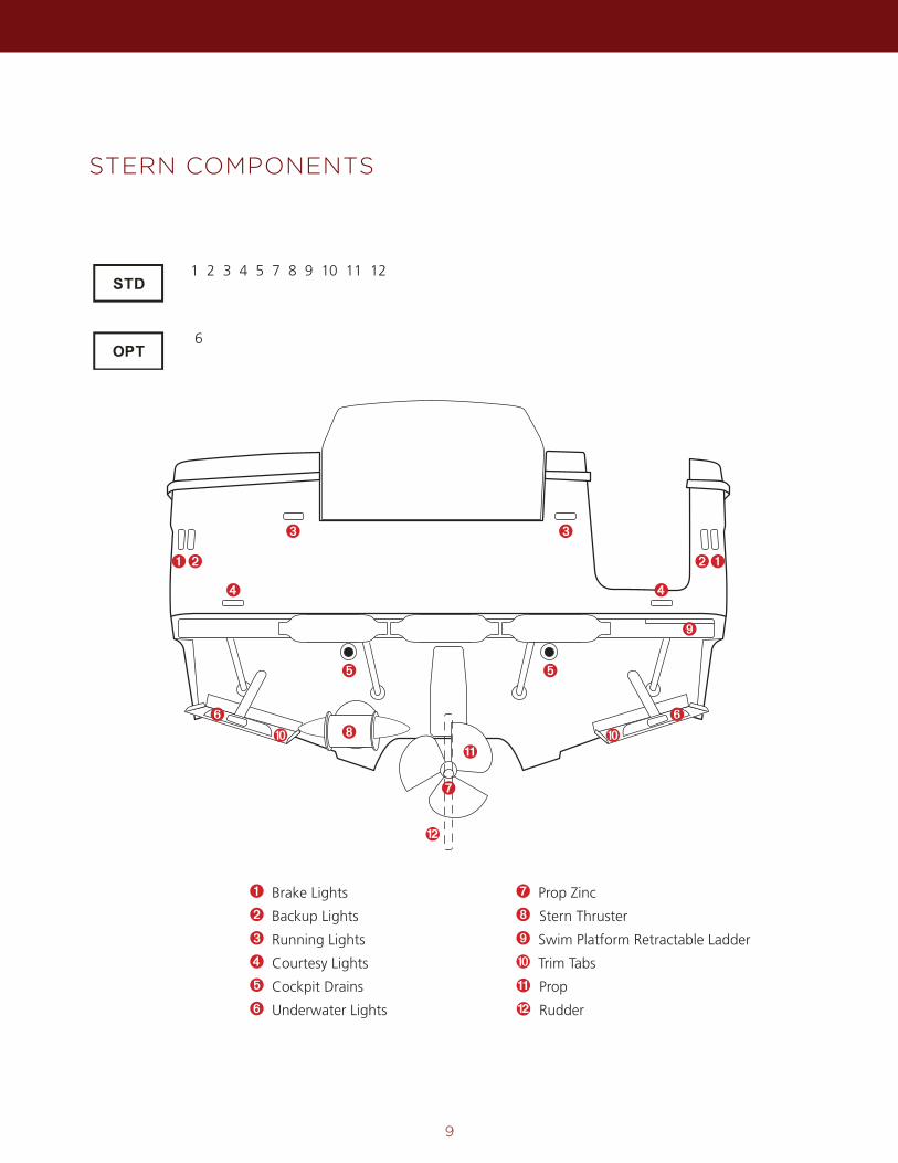
STERN COMPONENTS
1 2 3 4 5 7 8 9 10 11 12
6
➊ Brake Lights
➋ Backup Lights
➌ Running Lights
➍ Courtesy Lights
➎ Cockpit Drains
➏ Underwater Lights
➐ Prop Zinc
➑ Stern Thruster
➒ Swim Platform Retractable Ladder
➓ Trim Tabs
Prop
Rudder
11
12
➊ ➊
➍
➋ ➋
➎ ➎
➌ ➌
➏➏
➐
➑
➒
➓ ➓11
12
➍
FUSE LOCATION & VALUES
10
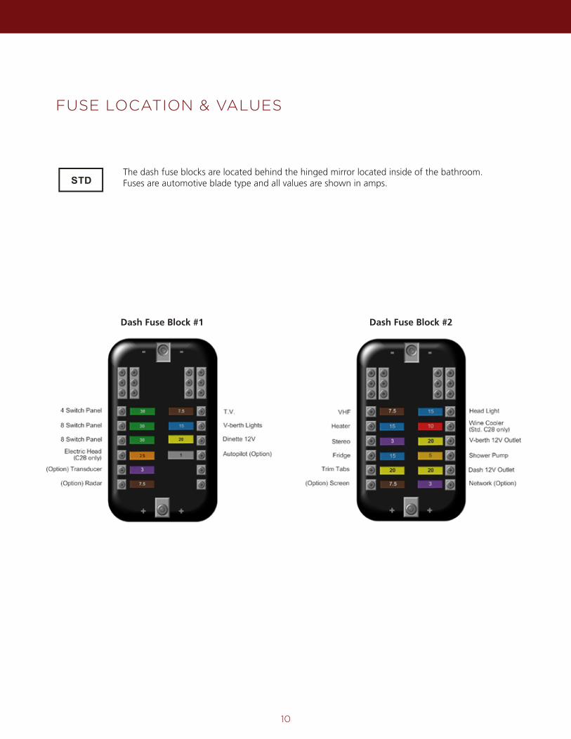
The dash fuse blocks are located behind the hinged mirror located inside of the bathroom. Fuses are automotive blade type and all values are shown in amps.
Dash Fuse Block #1 Dash Fuse Block #2
11
FUSE LOCATIONS AND VALUES CONTINUED
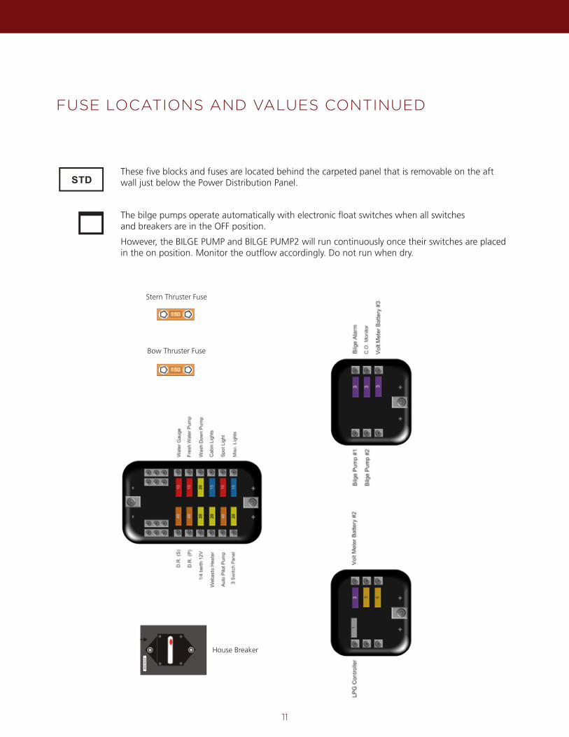
These five blocks and fuses are located behind the carpeted panel that is removable on the aft wall just below the Power Distribution Panel.
House Breaker
Bow Thruster Fuse
Stern Thruster Fuse
The bilge pumps operate automatically with electronic float switches when all switchesand breakers are in the OFF position.
However, the BILGE PUMP and BILGE PUMP2 will run continuously once their switches are placed in the on position. Monitor the outflow accordingly. Do not run when dry.
12
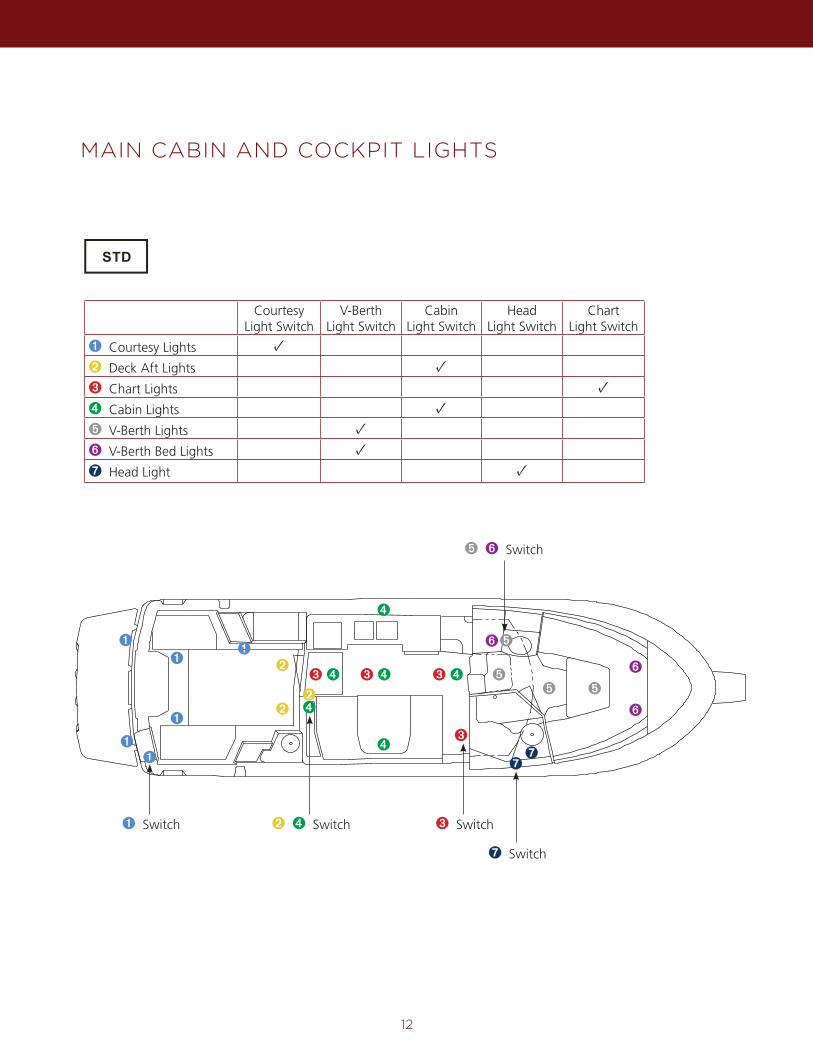
MAIN CABIN AND COCKPIT LIGHTS
Courtesy Light Switch
V-Berth Light Switch
Cabin Light Switch
Head Light Switch
Chart Light Switch
➊ Courtesy Lights ✓➋ Deck Aft Lights ✓➌ Chart Lights ✓➍ Cabin Lights ✓➎ V-Berth Lights ✓➏ V-Berth Bed Lights ✓➐ Head Light ✓
➋
➋
➌ ➌
➌
➌ ➏
➏
➐
➏
➎➎
➎
➎
➊
➊
➊➊
➊➊
➍ ➍ ➍
➍
➍
➊ Switch ➌ Switch
➐ Switch
➎ ➏ Switch
➋ ➍ Switch
➋➍
➐
13
BATTERY COMPARTMENT
13
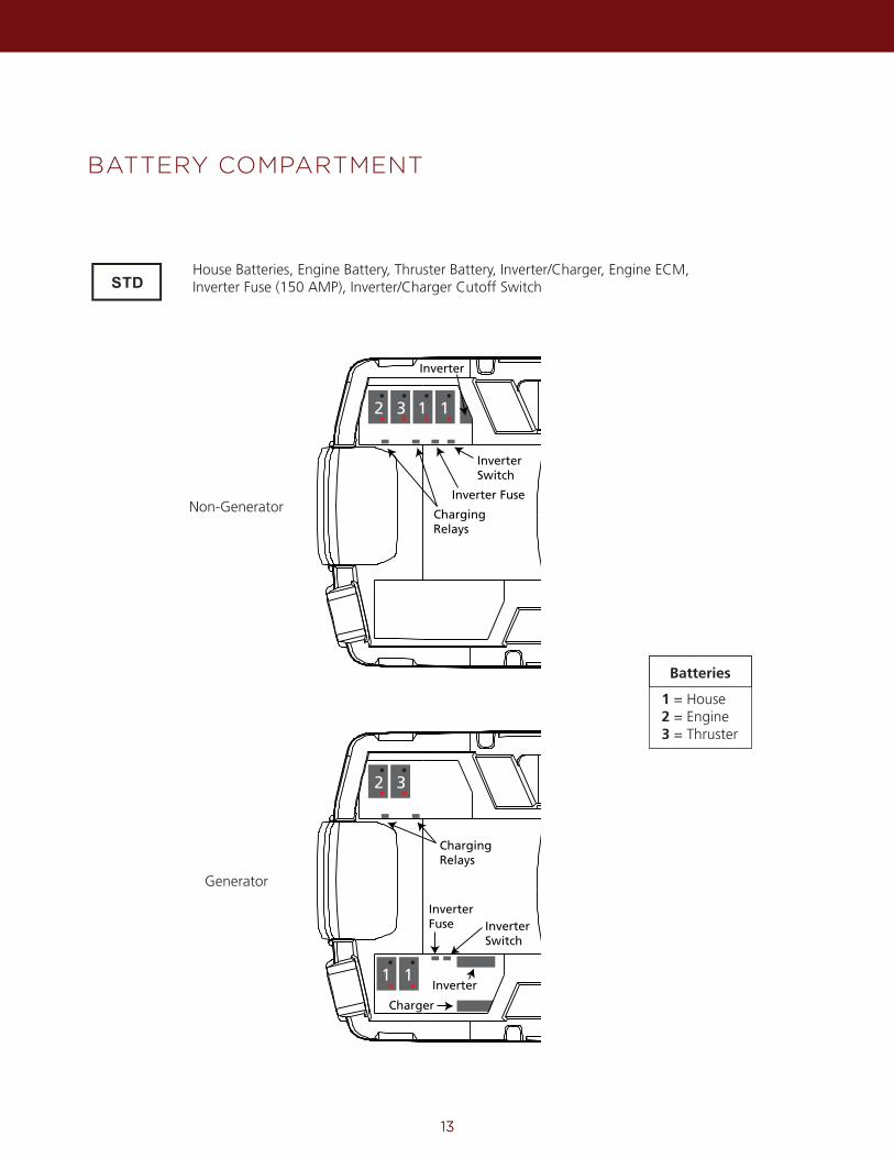
House Batteries, Engine Battery, Thruster Battery, Inverter/Charger, Engine ECM, Inverter Fuse (150 AMP), Inverter/Charger Cutoff Switch
Non-Generator
Generator
2 3 1 1
Inverter Switch
Inverter Fuse
Inverter
Charging Relays
2 3
1 1
Charging Relays
Inverter Switch
Inverter Fuse
Inverter
Charger
Batteries
1 = House2 = Engine3 = Thruster
POWER DISTRIBUTION CENTER
14
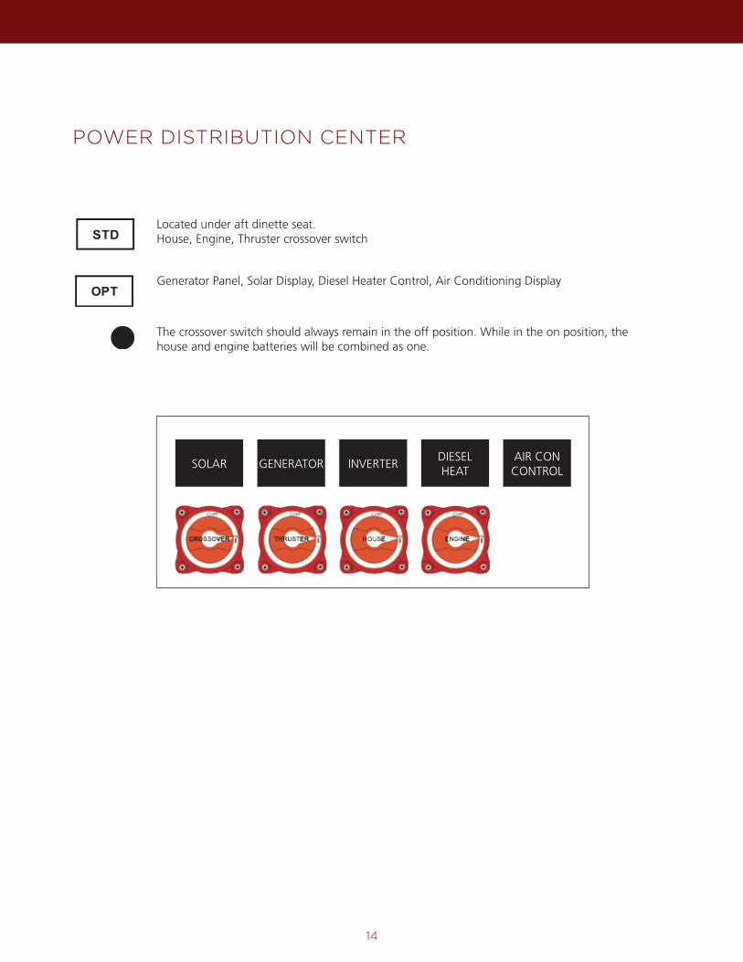
Generator Panel, Solar Display, Diesel Heater Control, Air Conditioning Display
The crossover switch should always remain in the off position. While in the on position, the house and engine batteries will be combined as one.
Located under aft dinette seat. House, Engine, Thruster crossover switch
SOLAR GENERATOR INVERTERDIESEL HEAT
AIR CON CONTROL
15
AC DISTRIBUTION PANEL, ROTARY SWITCH & DC VOLT METER
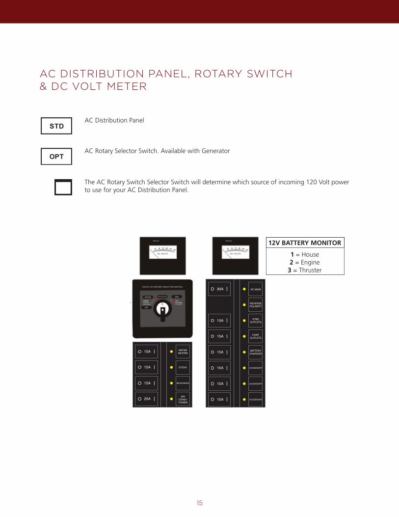
AC Rotary Selector Switch. Available with Generator
The AC Rotary Switch Selector Switch will determine which source of incoming 120 Volt power to use for your AC Distribution Panel.
AC Distribution Panel
30A AC MAIN
REVERSEPOLARITY
15A STBDOUTLETS
PORTOUTLETS
15A
15A
BATTERYCHARGER
15A
15A
15A
ACCESSORY
ACCESSORY
ACCESSORY
15A WATERHEATER
STOVE
15A
15A
MICROWAVE
AIRCONDI-TIONER
25A
AC VOLTS DC VOLTS
12V BATTERY MONITOR
1 = House2 = Engine
3 = Thruster
FUEL SYSTEM, ENGINE, GENERATOR & WEBASTO FURNACE
16
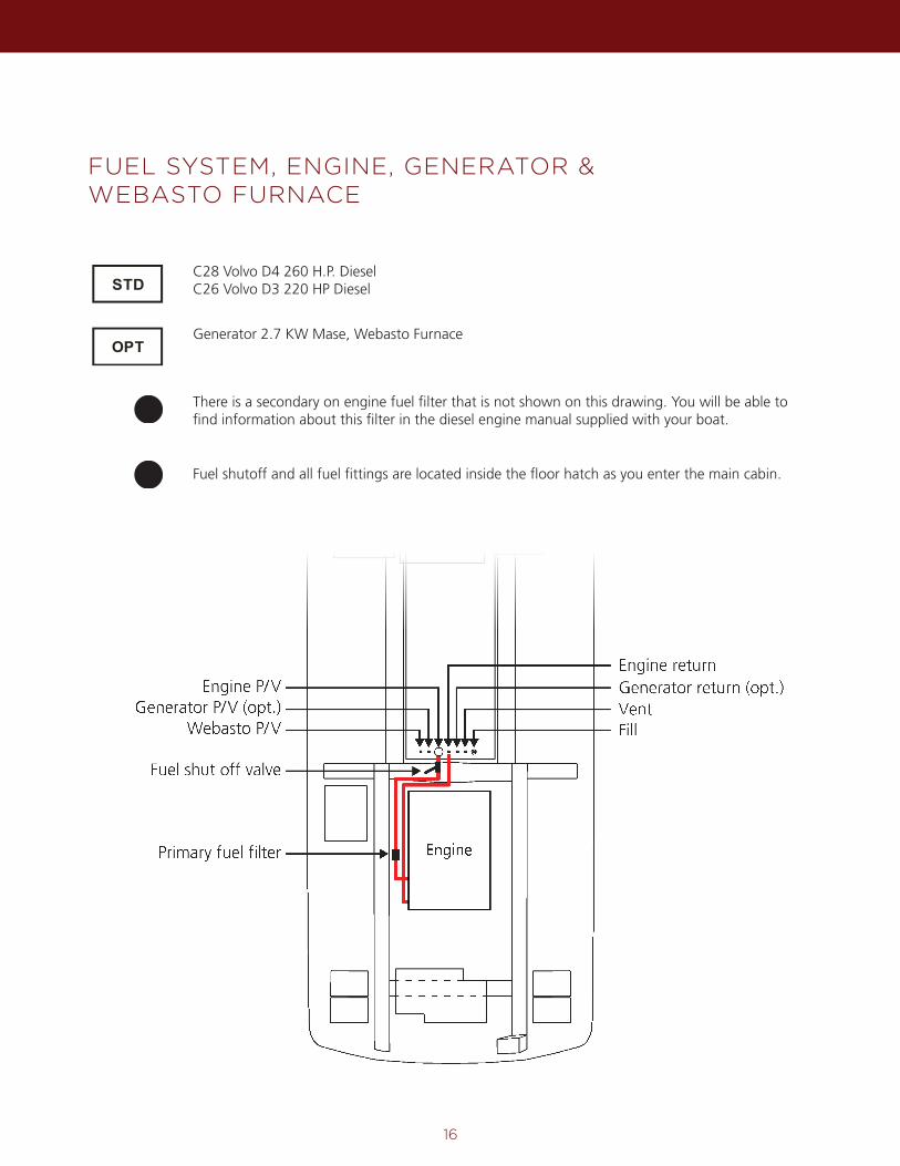
C28 Volvo D4 260 H.P. Diesel C26 Volvo D3 220 HP Diesel
Generator 2.7 KW Mase, Webasto Furnace
There is a secondary on engine fuel filter that is not shown on this drawing. You will be able to find information about this filter in the diesel engine manual supplied with your boat.
Fuel shutoff and all fuel fittings are located inside the floor hatch as you enter the main cabin.
Fill
Primary fuel filter
Fuel shut off valve
Webasto P/VGenerator P/V (opt.)
Engine P/VVentGenerator return (opt.)Engine return
Engine
17
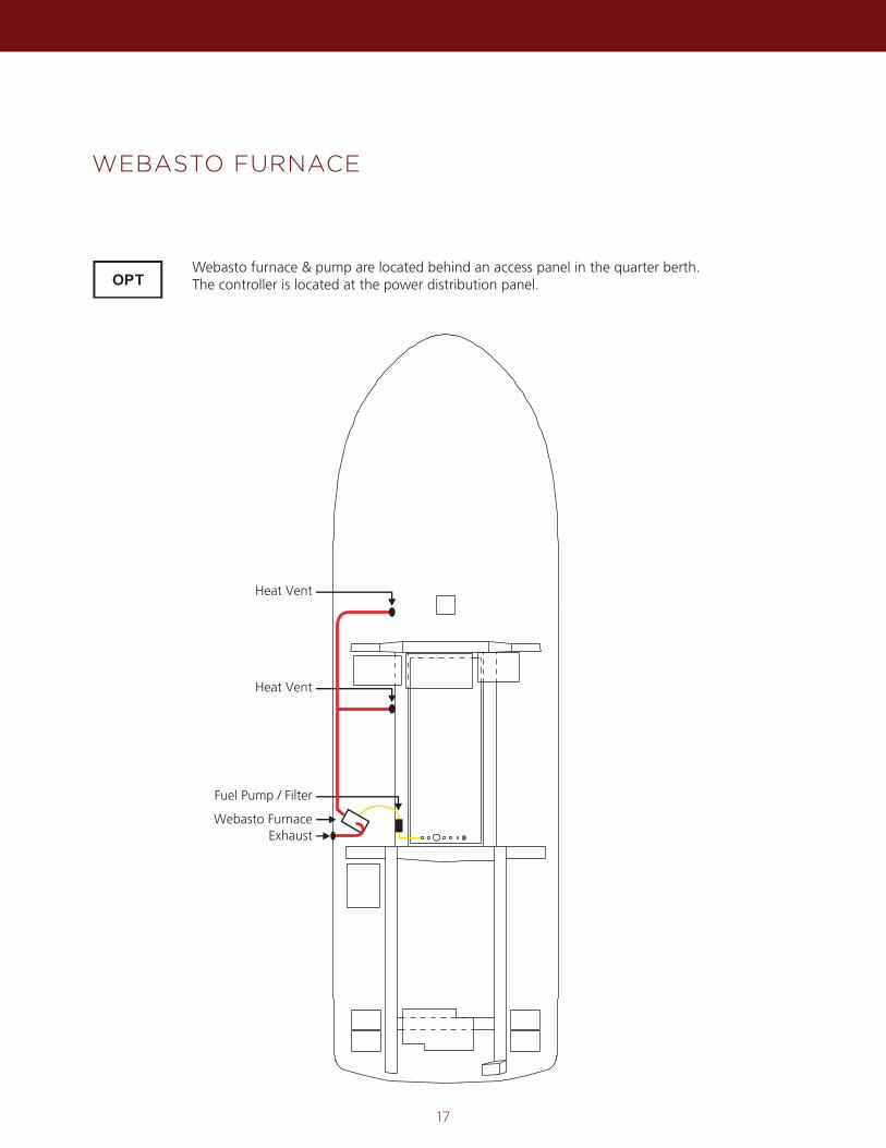
WEBASTO FURNACE
Webasto furnace & pump are located behind an access panel in the quarter berth.The controller is located at the power distribution panel.
Webasto Furnace
Fuel Pump / Filter
Heat Vent
Heat Vent
Exhaust
18
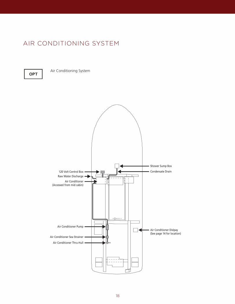
AIR CONDITIONING SYSTEM
Air Conditioning System
120 Volt Control Box
Air Conditioner Pump
Air Conditioner Sea Strainer
Air Conditioner Thru-Hull
Raw Water Discharge
Air Conditioner(Accessed from mid cabin)
Air Conditioner Dislpay(See page 14 for location)
Shower Sump Box
Condensate Drain
19
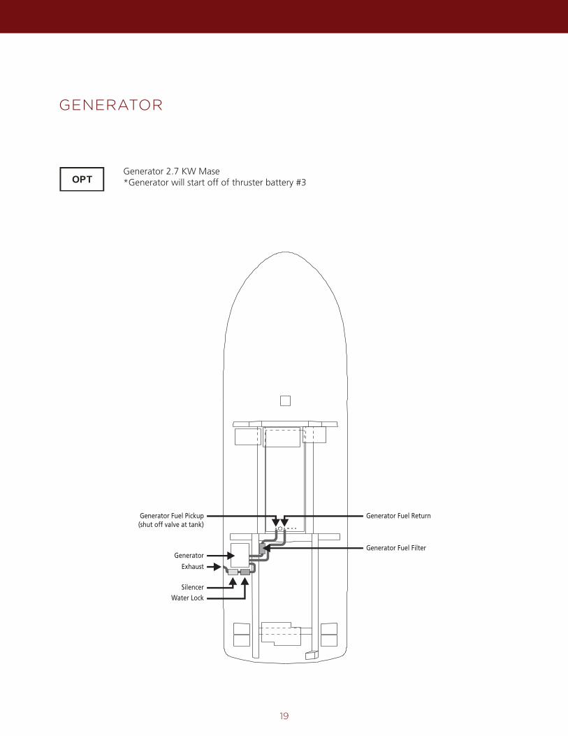
GENERATOR
Generator 2.7 KW Mase*Generator will start off of thruster battery #3
Generator Fuel ReturnGenerator Fuel Pickup(shut off valve at tank)
Generator
Exhaust
Water Lock
Silencer
Generator Fuel Filter
20
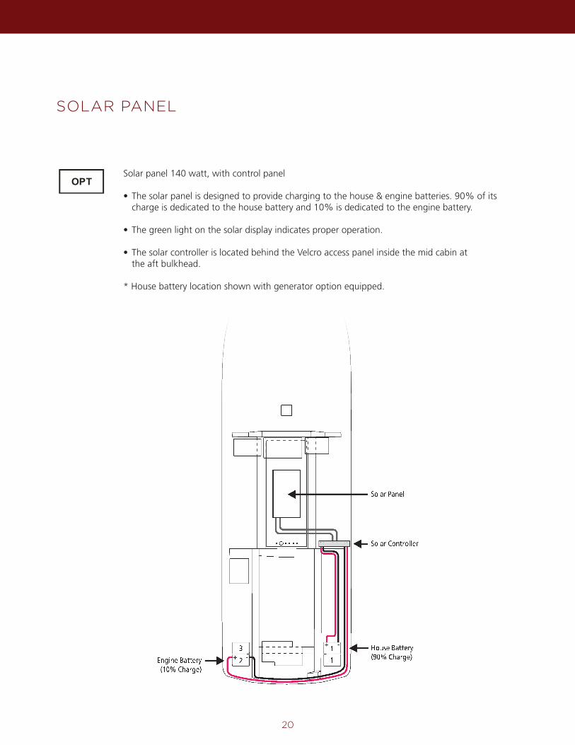
SOLAR PANEL
Solar panel 140 watt, with control panel
• The solar panel is designed to provide charging to the house & engine batteries. 90% of its charge is dedicated to the house battery and 10% is dedicated to the engine battery.
• The green light on the solar display indicates proper operation.
• The solar controller is located behind the Velcro access panel inside the mid cabin at the aft bulkhead.
* House battery location shown with generator option equipped.
Engine Battery(10% Charge)
2+ -
+ -3 1
1
Solar Panel
Solar Controller
House Battery(90% Charge)
21
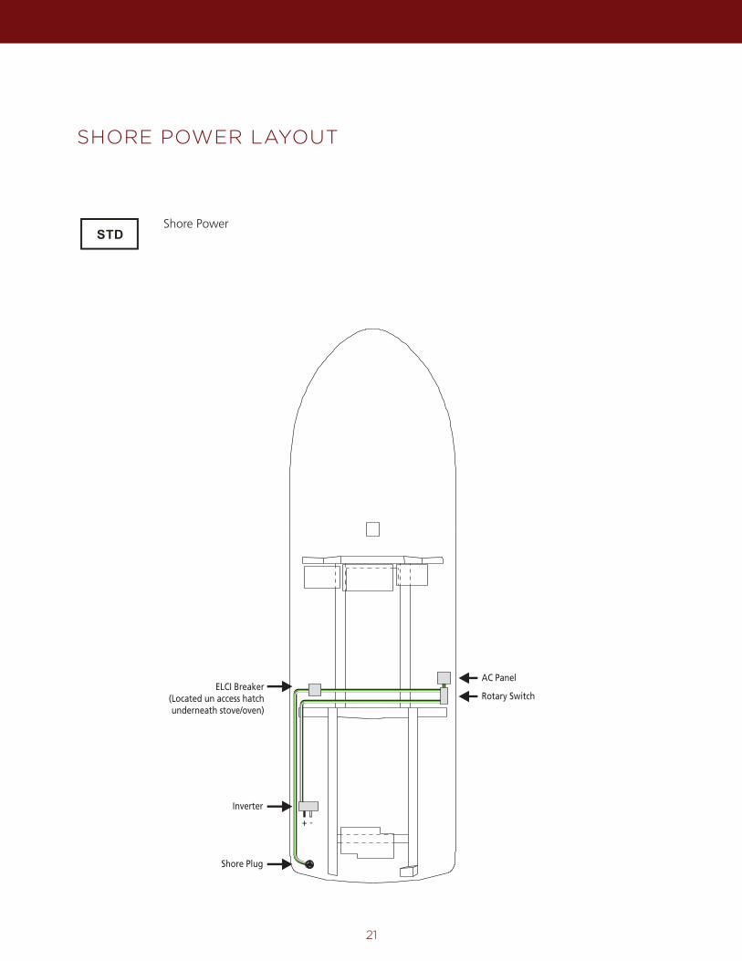
SHORE POWER LAYOUT
Shore Power
ELCI Breaker(Located un access hatchunderneath stove/oven)
Inverter
+ -
Shore Plug
Rotary Switch
AC Panel
22
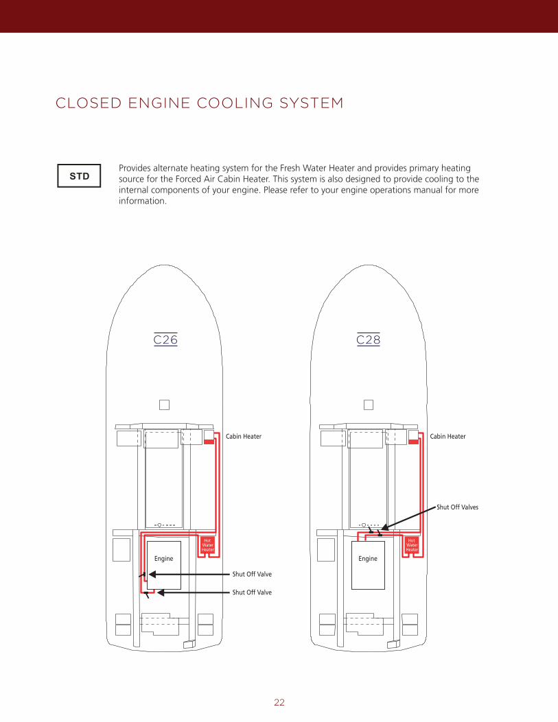
CLOSED ENGINE COOLING SYSTEM
Provides alternate heating system for the Fresh Water Heater and provides primary heating source for the Forced Air Cabin Heater. This system is also designed to provide cooling to the internal components of your engine. Please refer to your engine operations manual for more information.
Hot WaterHeater
Cabin Heater
Engine
Shut Off Valves
Shut Off Valve
Hot WaterHeater
Cabin Heater
Engine
Shut Off Valve
C28C26
23
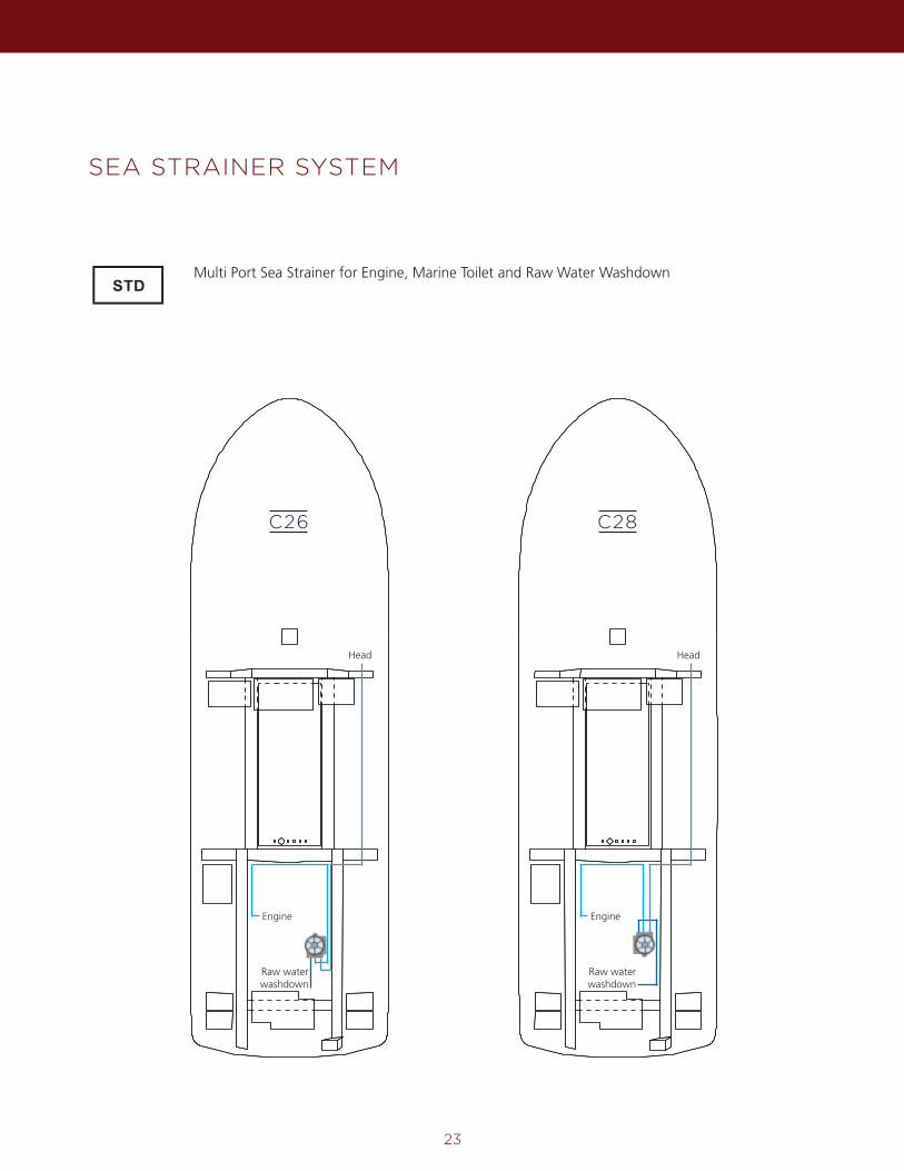
SEA STRAINER SYSTEM
Multi Port Sea Strainer for Engine, Marine Toilet and Raw Water Washdown
EngineEngine
HeadHead
Raw water washdown
Raw water washdown
C28C26
24
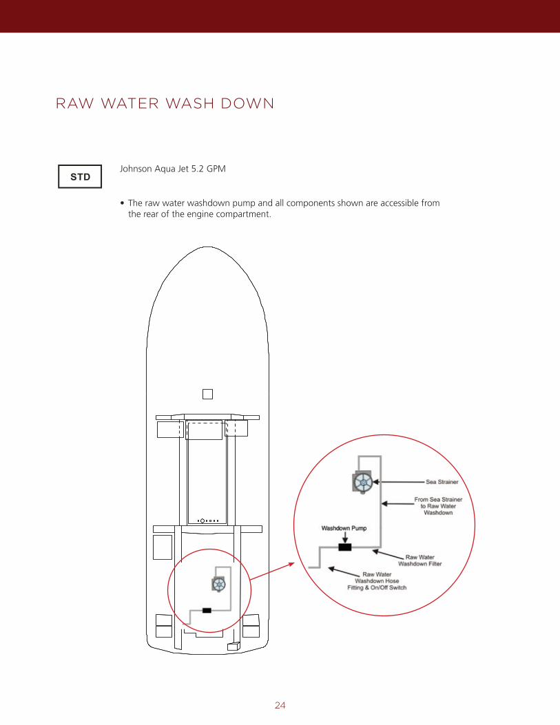
RAW WATER WASH DOWN
Johnson Aqua Jet 5.2 GPM
• The raw water washdown pump and all components shown are accessible from the rear of the engine compartment.
25
FRESH WATER PLUMBING SYSTEM
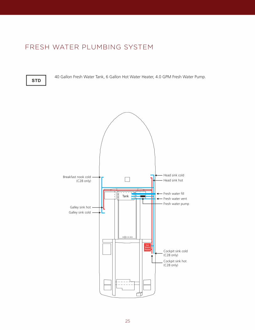
40 Gallon Fresh Water Tank, 6 Gallon Hot Water Heater, 4.0 GPM Fresh Water Pump.
Galley sink hot
Galley sink cold
Cockpit sink cold(C28 only)
Fresh water vent
Fresh water pump
Breakfast nook cold(C28 only)
Fresh water fill
Head sink hot
Head sink cold
Cockpit sink hot(C28 only)
Hot WaterHeater
Tank
26
SHOWER SUMP
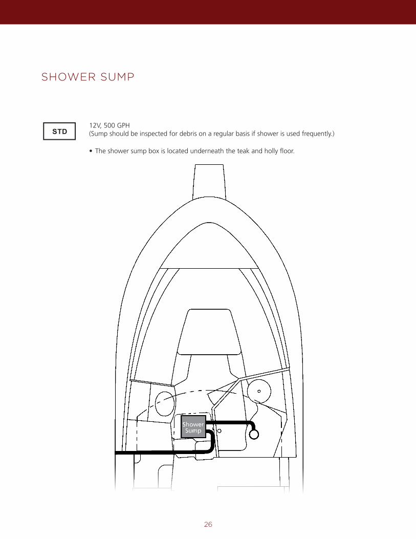
12V, 500 GPH (Sump should be inspected for debris on a regular basis if shower is used frequently.)
ShowerSump
• The shower sump box is located underneath the teak and holly floor.
27
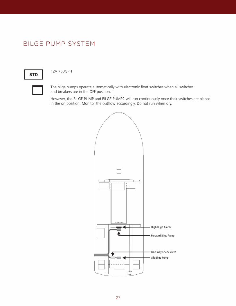
BILGE PUMP SYSTEM
The bilge pumps operate automatically with electronic float switches when all switchesand breakers are in the OFF position.
However, the BILGE PUMP and BILGE PUMP2 will run continuously once their switches are placed in the on position. Monitor the outflow accordingly. Do not run when dry.
12V 750GPH
2
1
High Bilge Alarm
Aft Bilge Pump
Forward Bilge Pump
One Way Check Valve
28
WASTE SYSTEM WITH MACERATOR PUMP
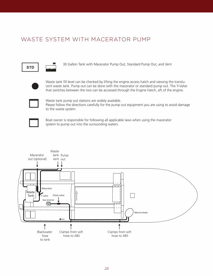
Waste tank fill level can be checked by lifting the engine access hatch and viewing the translu-cent waste tank. Pump out can be done with the macerator or standard pump out. The Y-Valve that switches between the two can be accessed through the Engine Hatch, aft of the engine.
30 Gallon Tank with Macerator Pump Out, Standard Pump Out, and Vent
Waste tank pump out stations are widely available.Please follow the directions carefully for the pump out equipment you are using to avoid damage to the waste system.
Boat owner is responsible for following all applicable laws when using the maceratorsystem to pump out into the surrounding waters.
Macerator out (optional)
Wastetankvent
Pump out
Check valve
Clamps from soft hose to ABS
Clamps from soft hose to ABS
Blackwater hose
to tank
Waste Tank
Macerator
Y valve
Marine Head
Sea strainer
29
MAST SET UP AND TAKEDOWN
MAST SET UP PROCEDURE
1. Remove the two black plastic wing nuts from the mast base.2. While supporting the mast, remove the pin in the support bar.3. Raise the mast to its full extension and ensure that it fits correctly over the mounting studs on the roof
mounting plate.4. Secure the stainless steel retaining bar in the appropriate clip attached next to the v-berth escape hatch.5. Attach the two black plastic wing nuts to the mounting studs and hand tighten securely.
MAST TAKE DOWN PROCEDURE
1. Remove the two black plastic wing nuts from the mast base mounting studs.2. Carefully lower the mast onto the stainless steel support bar and attach retaining pin.3. Attach the black plastic wing nuts back onto the screws on the mast mounting plate and secure them
for storage by hand tightening.4. Recommend securing the mast with a tie down.
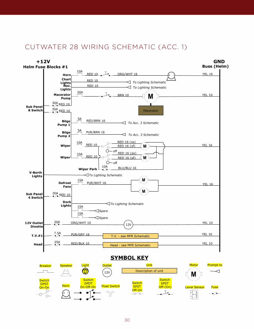
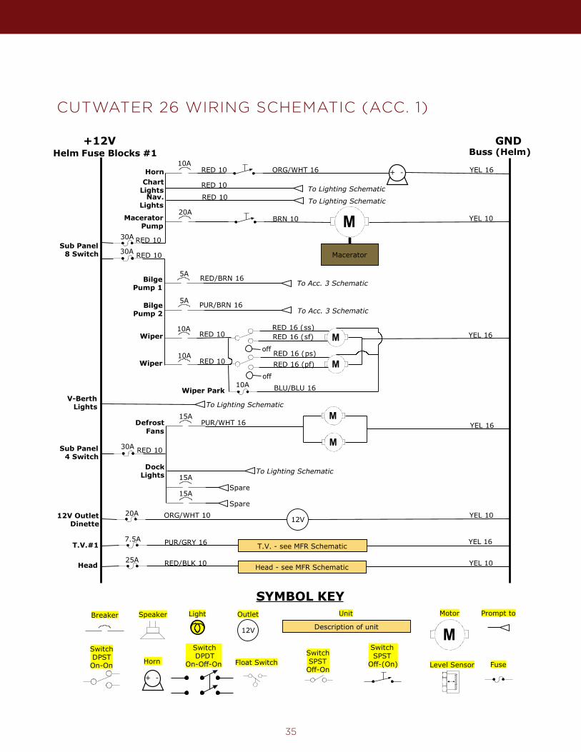
CUTWATER 28 WIRING SCHEMATIC (ACC. 1)
30
Cutwater C-28 Accessories 1+12V GND
Helm Fuse Blocks #110A
+ -
30A
ORG/WHT 16 YEL 16
RED 10
10A
10AM
M
YEL 16RED 10
RED 10
RED 16 (ss)
RED 16 (ps)
BLU/BLU 16Wiper Park
Horn
10A
Sub Panel8 Switch
Buss (Helm)
ELECTRICAL SCHEMATIC
Wiper
Wiper
DefrostFans
4-05-13
20A YEL 10ORG/WHT 1012V OutletDinette 12V
RED 10
PUR/WHT 16M
M
YEL 16
To Lighting SchematicRED 10
To Lighting SchematicRED 10
YEL 1020A
M
Macerator
BRN 10MaceratorPump
RED 1030A
BilgePump 2
BilgePump 1
5A
5A
RED/BRN 16
PUR/BRN 16
To Acc. 3 Schematic
To Acc. 3 Schematic
off
off
RED 16 (sf)
RED 16 (pf)
T.V.#17.5A
T.V. - see MFR Schematic YEL 16PUR/GRY 16
Sub Panel4 Switch
RED 1030A
15A
15A
15ASpare
Spare
To Lighting Schematic
ChartLights
DockLights
Head25A
Head - see MFR Schematic YEL 10RED/BLK 10
Nav.Lights
V-BerthLights To Lighting Schematic
Description of unit12V
AB
C
+ -
Level Sensor
Breaker Light
Float Switch FuseHorn
Prompt toOutlet
SwitchSPSTOff-On
SwitchSPST
Off-(On)
Unit
SwitchDPDT
On-Off-On
Speaker
MMotor
SYMBOL KEY
SwitchDPSTOn-On

31
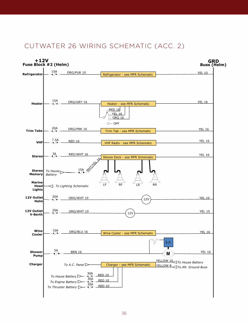
CUTWATER 28 WIRING SCHEMATIC (ACC. 2)Cutwater C-28 Accessories 2
+12VFuse Block #2 (Helm) Buss (Helm)
GRDELECTRICAL SCHEMATIC
15ARefrigerator - see MFR Schematic
ORG/PUR 10 YEL 10Refrigerator
Trim Tab - see MFR SchematicORG/PNK 1620A YEL 16Trim Tabs
ORG/GRY 16 YEL 16Heater Heater - see MFR Schematic
YEL 16ORG 16
15A
11-25-13
RED 16
OFF
YEL 16ORG/BLU 16 Wine Cooler - see MFR SchematicWineCooler
Stereo Deck - see MFR Schematic
LF RF LR RR
3A YEL 16RED/WHT 16Stereo
To HouseBattery
WHT/
YEL 1
6
12V20A YEL 10ORG/WHT 1012V Outlet
Helm
20A YEL 10ORG/WHT 10 12V12V Outlet
V-Berth
10A
VHF Radio - see MFR SchematicYEL 16RED 16VHF
ShowerPump
5AMBRN 16
S.P.
YEL 16
YEL 16ORG/BLU 16 Wine Cooler - see MFR SchematicWine
Cooler10A
MarineHead
LightsTo Lighting Schematic
7.5A
StereoMemory
15A
Charger - see MFR SchematicCharger
To House Battery
To Engine Battery
To Thruster Battery
RED 10
RED 10
RED 10
30A
30A
30A
To House BatteryTo Aft. Ground Buss
YELLOW 10YELLOW 8To A.C. Panel
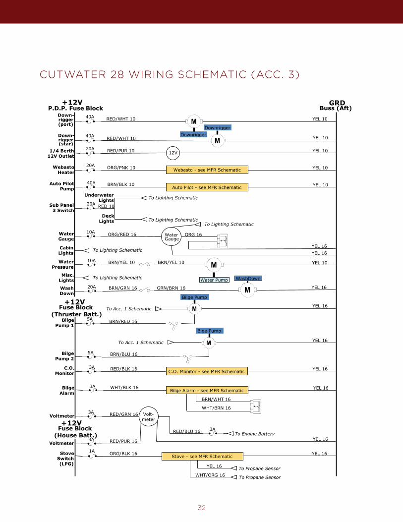
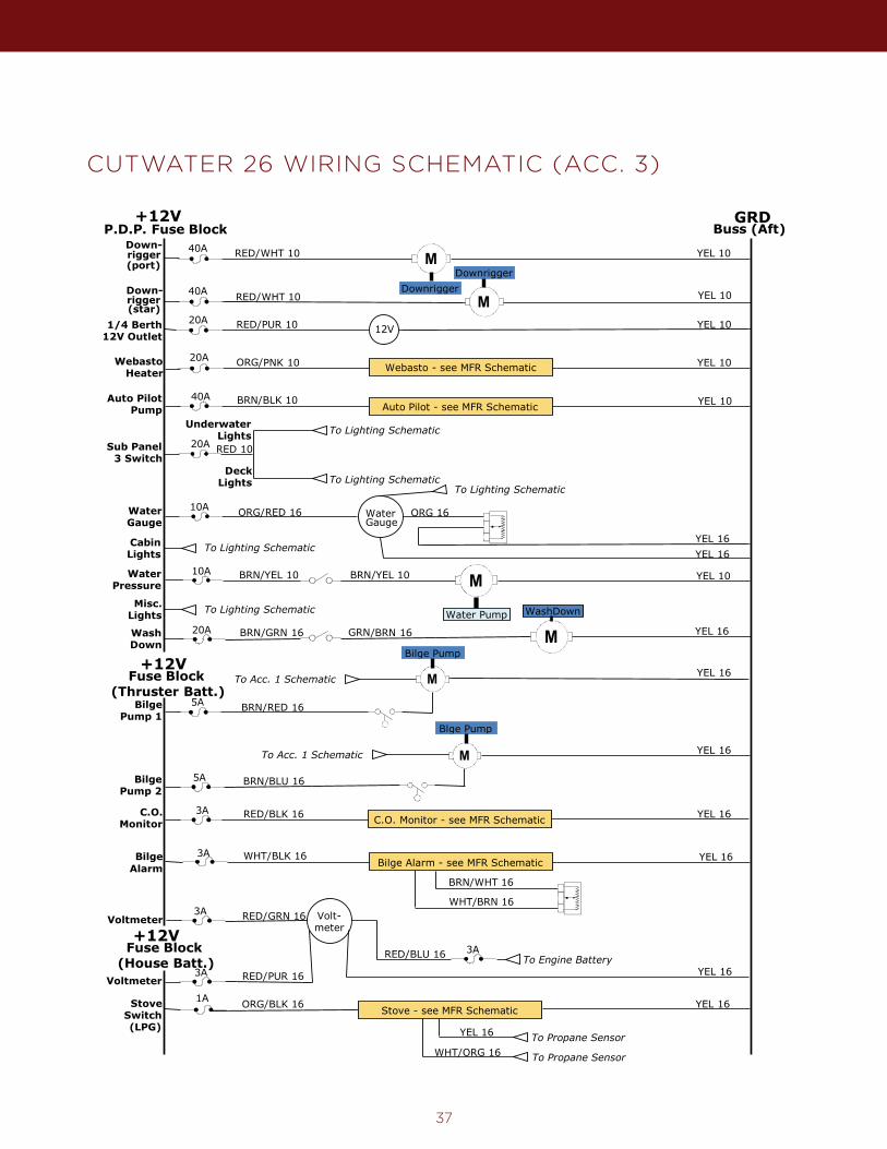
CUTWATER 28 WIRING SCHEMATIC (ACC. 3)
32
Cutwater C-28 Accessories 3+12V
P.D.P. Fuse Block Buss (Aft)GRD
WashDown
ELECTRICAL SCHEMATIC
12VRED/PUR 101/4 Berth12V Outlet
YEL 10
4-05-13
CabinLights To Lighting Schematic
10AM
Water Pump
YEL 10BRN/YEL 10WaterPressure
BilgePump 2
BilgePump 1
MTo Acc. 1 Schematic
Bilge Pump+12V
Fuse Block(Thruster Batt.)
5A
5A
MTo Acc. 1 Schematic
Blge Pump
BRN/RED 16
BRN/BLU 16
YEL 16
YEL 16
+12VFuse Block
(House Batt.)
Volt-meter
3A
3A
RED/GRN 16
RED/PUR 16Voltmeter
Voltmeter
YEL 16
3ARED/BLU 16 To Engine Battery
20A MBRN/GRN 16 YEL 16
WashDown
20A
GRN/BRN 16
M
M
Down-rigger(port)
Down-rigger
40A
40A
YEL 10
YEL 10
RED/WHT 10
RED/WHT 10
DownriggerDownrigger
(star)
ORG/PNK 10WebastoHeater
YEL 1020A
Auto PilotPump
40AAuto Pilot - see MFR Schematic YEL 10BRN/BLK 10
Sub Panel3 Switch
RED 1020A
To Lighting SchematicDeck
Lights
To Lighting SchematicUnderwaterLights
WaterGauge
AB
C
ORG 16WaterGauge
To Lighting Schematic
YEL 16YEL 16
ORG/RED 1610A
BRN/YEL 10
Misc.Lights To Lighting Schematic
1AStoveSwitch(LPG)
ORG/BLK 16 Stove - see MFR Schematic YEL 16
YEL 16
WHT/ORG 16To Propane Sensor
To Propane Sensor
C.O.Monitor
3AC.O. Monitor - see MFR Schematic YEL 16RED/BLK 16
BilgeAlarm
WHT/BLK 16Bilge Alarm - see MFR Schematic YEL 16
BRN/WHT 16
WHT/BRN 16
AB
C
3A
Webasto - see MFR Schematic
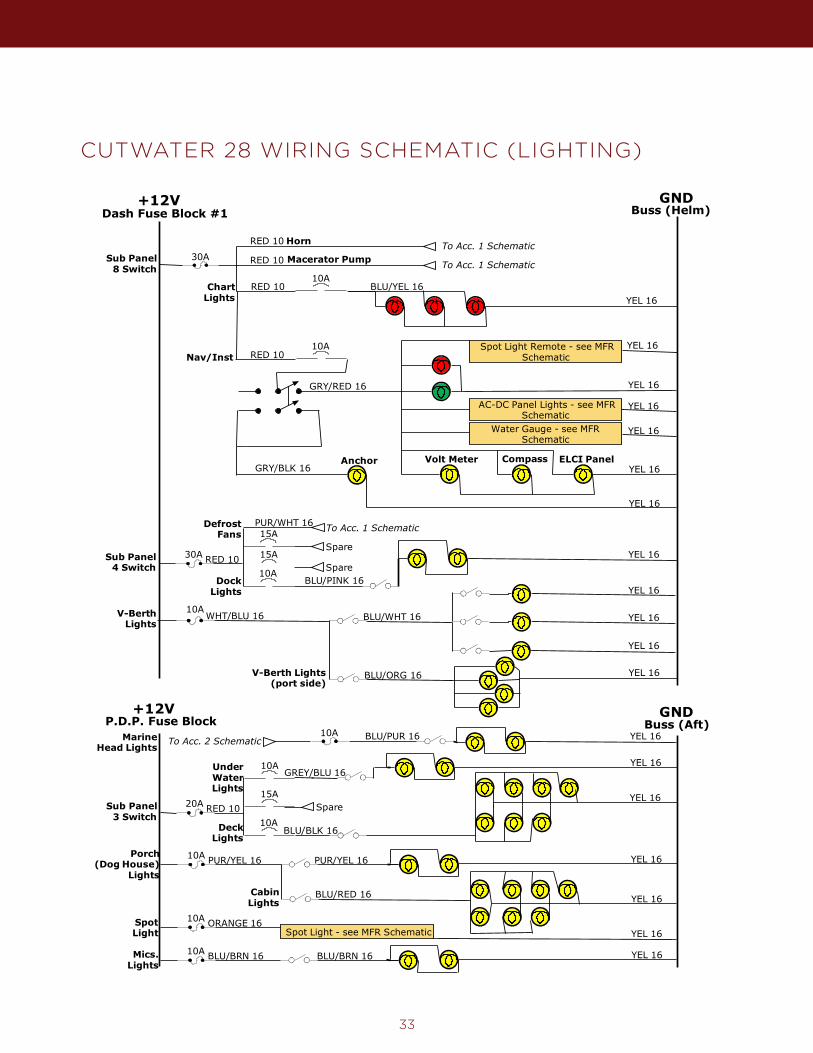
33
CUTWATER 28 WIRING SCHEMATIC (LIGHTING)
+12V GNDCutwater C-28 Lighting
30A
Buss (Helm)Dash Fuse Block #1
Sub Panel8 Switch
RED 10 To Acc. 1 SchematicHorn
+12V
4-05-13
ELECTRICAL SCHEMATIC
To Acc. 1 SchematicMacerator Pump
MarineHead Lights
10A YEL 16BLU/PUR 16
DeckLights
YEL 16
Porch(Dog House)
Lights
10A PUR/YEL 16 YEL 16PUR/YEL 16
To Acc. 2 Schematic
YEL 16
10ANav/Inst
AC-DC Panel Lights - see MFRSchematic
CompassVolt MeterAnchorYEL 16
YEL 16
YEL 16
GRY/RED 16
GRY/BLK 16
RED 10
ELCI Panel
Water Gauge - see MFRSchematic
YEL 16
10A
YEL 16BLU/YEL 16Chart
Lights
RED 10
DefrostFans
PUR/WHT 16
Sub Panel4 Switch
RED 1030A
15A
15ASpare
SpareDock
Lights
To Acc. 1 Schematic
RED 10
10A
YEL 16
BLU/PINK 16
YEL 16
YEL 16
10AWHT/BLU 16V-Berth
Lights
YEL 16
BLU/WHT 16
BLU/ORG 16 YEL 16V-Berth Lights(port side)
P.D.P. Fuse Block
Sub Panel3 Switch
RED 1020A
10A
10A
15ASpare
UnderWaterLights
BLU/BLK 16
CabinLights
GREY/BLU 16YEL 16
YEL 16BLU/RED 16
Mics.Lights
10A BLU/BRN 16 YEL 16BLU/BRN 16
GNDBuss (Aft)
Spot Light Remote - see MFRSchematic
YEL 16
SpotLight
10A ORANGE 16Spot Light - see MFR Schematic YEL 16
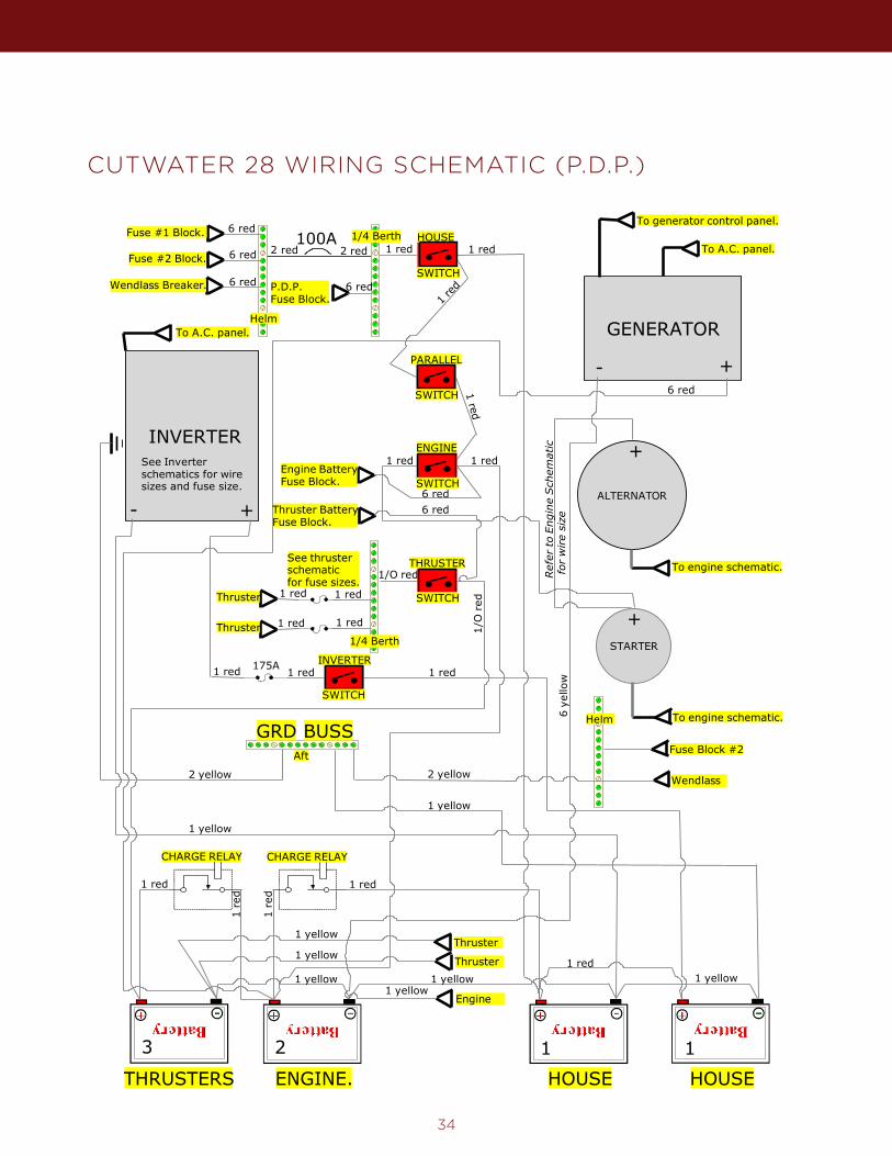
CUTWATER 28 WIRING SCHEMATIC (P.D.P.)
34
ALTERNATOR
100A
INVERTERSee Inverterschematics for wiresizes and fuse size.
To A.C. panel.
HOUSE HOUSETHRUSTERS ENGINE.
GENERATOR
- +
To A.C. panel.
To generator control panel.
BUSSGRD
To engine schematic.
STARTER
To engine schematic.
+-
3 2 1
+
+
2 red 1 red 1 red
1 red1 red
6 red
6 ye
llow
1 red
2 yellow
1/O red
1/O
red
1 red
1 red1 red
1 redThruster
Thruster
1 red
1 re
d
1 re
d
1 red
1 yellow 1 yellow1 yellow
1 yellow
11-25-13
Cutwater C-28 Power DistributionHOUSE
ENGINE
THRUSTER
INVERTER
PARALLEL
ELECTRICAL SCHEMATIC
See thrusterschematicfor fuse sizes.
CHARGE RELAY CHARGE RELAY
SWITCH
SWITCH
SWITCH
SWITCH
SWITCH
Thruster1 yellow
1 red
1 yellow
1 red1 red1 red 175A
Engine1 yellow
Thruster1 yellow
Engine BatteryFuse Block.
Thruster BatteryFuse Block.
6 red6 red
2 red
P.D.P.Fuse Block.
Fuse #1 Block.
6 red
Fuse #2 Block.
Wendlass Breaker.
6 red
6 red
6 red
1 red
2 yellow
Fuse Block #2
Wendlass
1/4 Berth
1/4 Berth
Aft
Helm
Helm
Ref
er to
Engi
ne S
chem
atic
for
wire
size
1
35
CUTWATER 26 WIRING SCHEMATIC (ACC. 1)Cutwater C-26 Accessories 1
+12V GNDHelm Fuse Blocks #1
10A+ -
30A
ORG/WHT 16 YEL 16
RED 10
10A
10AM
M
YEL 16RED 10
RED 10
RED 16 (ss)
RED 16 (ps)
BLU/BLU 16Wiper Park
Horn
10A
Sub Panel8 Switch
Buss (Helm)
ELECTRICAL SCHEMATIC
Wiper
Wiper
DefrostFans
4-06-13
20A YEL 10ORG/WHT 1012V OutletDinette 12V
RED 10
PUR/WHT 16M
M
YEL 16
To Lighting SchematicRED 10
To Lighting SchematicRED 10
YEL 1020A
M
Macerator
BRN 10MaceratorPump
RED 1030A
BilgePump 2
BilgePump 1
5A
5A
RED/BRN 16
PUR/BRN 16
To Acc. 3 Schematic
To Acc. 3 Schematic
off
off
RED 16 (sf)
RED 16 (pf)
T.V.#17.5A
T.V. - see MFR Schematic YEL 16PUR/GRY 16
Sub Panel4 Switch
RED 1030A
15A
15A
15ASpare
Spare
To Lighting Schematic
ChartLights
DockLights
Head25A
Head - see MFR Schematic YEL 10RED/BLK 10
Nav.Lights
V-BerthLights To Lighting Schematic
Description of unit12V
AB
C
+ -
Level Sensor
Breaker Light
Float Switch FuseHorn
Prompt toOutlet
SwitchSPSTOff-On
SwitchSPST
Off-(On)
Unit
SwitchDPDT
On-Off-On
Speaker
MMotor
SYMBOL KEY
SwitchDPSTOn-On
36
CUTWATER 26 WIRING SCHEMATIC (ACC. 2)Cutwater C-26 Accessories 2+12V
Fuse Block #2 (Helm) Buss (Helm)GRD
ELECTRICAL SCHEMATIC
15ARefrigerator - see MFR Schematic
ORG/PUR 10 YEL 10Refrigerator
Trim Tab - see MFR SchematicORG/PNK 1620A YEL 16Trim Tabs
ORG/GRY 16 YEL 16Heater Heater - see MFR Schematic
YEL 16ORG 16
15A
11-25-13
RED 16
OFF
Stereo Deck - see MFR Schematic
LF RF LR RR
3A YEL 16RED/WHT 16Stereo
To HouseBattery
WHT/
YEL 1
6
12V20A YEL 10ORG/WHT 1012V Outlet
Helm
20A YEL 10ORG/WHT 10 12V12V Outlet
V-Berth
VHF Radio - see MFR SchematicYEL 16RED 16VHF
ShowerPump
5AMBRN 16
S.P.
YEL 16
YEL 16ORG/BLU 16 Wine Cooler - see MFR SchematicWine
Cooler10A
MarineHead
LightsTo Lighting Schematic
7.5A
StereoMemory
15A
Charger - see MFR SchematicCharger
To House Battery
To Engine Battery
To Thruster Battery
RED 10
RED 10
RED 10
30A
30A
30A
To House BatteryTo Aft. Ground Buss
YELLOW 10YELLOW 8To A.C. Panel
37
CUTWATER 26 WIRING SCHEMATIC (ACC. 3)Cutwater C-26 Accessories 3
+12VP.D.P. Fuse Block Buss (Aft)
GRD
WashDown
ELECTRICAL SCHEMATIC
12VRED/PUR 101/4 Berth12V Outlet
YEL 10
4-06-13
CabinLights To Lighting Schematic
10AM
Water Pump
YEL 10BRN/YEL 10WaterPressure
BilgePump 2
BilgePump 1
MTo Acc. 1 Schematic
Bilge Pump+12V
Fuse Block(Thruster Batt.)
5A
5A
MTo Acc. 1 Schematic
Blge Pump
BRN/RED 16
BRN/BLU 16
YEL 16
YEL 16
+12VFuse Block
(House Batt.)
Volt-meter
3A
3A
RED/GRN 16
RED/PUR 16Voltmeter
Voltmeter
YEL 16
3ARED/BLU 16 To Engine Battery
20A MBRN/GRN 16 YEL 16
WashDown
20A
GRN/BRN 16
M
M
Down-rigger(port)
Down-rigger
40A
40A
YEL 10
YEL 10
RED/WHT 10
RED/WHT 10
DownriggerDownrigger
(star)
ORG/PNK 10WebastoHeater
YEL 1020A
Auto PilotPump
40AAuto Pilot - see MFR Schematic YEL 10BRN/BLK 10
Sub Panel3 Switch
RED 1020A
To Lighting SchematicDeck
Lights
To Lighting SchematicUnderwaterLights
WaterGauge
AB
C
ORG 16WaterGauge
To Lighting Schematic
YEL 16YEL 16
ORG/RED 1610A
BRN/YEL 10
Misc.Lights To Lighting Schematic
1AStoveSwitch(LPG)
ORG/BLK 16 Stove - see MFR Schematic YEL 16
YEL 16
WHT/ORG 16To Propane Sensor
To Propane Sensor
C.O.Monitor
3AC.O. Monitor - see MFR Schematic YEL 16RED/BLK 16
BilgeAlarm
WHT/BLK 16Bilge Alarm - see MFR Schematic YEL 16
BRN/WHT 16
WHT/BRN 16
AB
C
3A
Webasto - see MFR Schematic
38
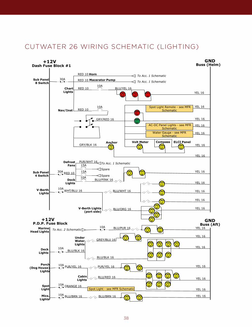
+12V GNDCutwater C-26 Lighting
30A
Buss (Helm)Dash Fuse Block #1
Sub Panel8 Switch
RED 10 To Acc. 1 SchematicHorn
+12V
4-06-13
ELECTRICAL SCHEMATIC
To Acc. 1 SchematicMacerator Pump
MarineHead Lights
10A YEL 16BLU/PUR 16
DeckLights
YEL 16
Porch(Dog House)
Lights
10A PUR/YEL 16 YEL 16PUR/YEL 16
To Acc. 2 Schematic
YEL 16
10ANav/Inst
AC-DC Panel Lights - see MFRSchematic
CompassVolt MeterAnchorYEL 16
YEL 16
YEL 16
GRY/RED 16
GRY/BLK 16
RED 10
ELCI Panel
Water Gauge - see MFRSchematic
YEL 16
10A
YEL 16BLU/YEL 16Chart
Lights
RED 10
DefrostFans
PUR/WHT 16
Sub Panel4 Switch
RED 1030A
15A
15ASpare
SpareDock
Lights
To Acc. 1 Schematic
RED 10
10A
YEL 16
BLU/PINK 16
YEL 16
YEL 16
10AWHT/BLU 16V-Berth
Lights
YEL 16
BLU/WHT 16
BLU/ORG 16 YEL 16V-Berth Lights(port side)
P.D.P. Fuse Block
10A
UnderWaterLights
BLU/BLK 16
CabinLights
GREY/BLU 16YEL 16
YEL 16BLU/RED 16
Mics.Lights
10A BLU/BRN 16 YEL 16BLU/BRN 16
GNDBuss (Aft)
Spot Light Remote - see MFRSchematic
YEL 16
SpotLight
10A ORANGE 16Spot Light - see MFR Schematic YEL 16
BLU/BLK 16
CUTWATER 26 WIRING SCHEMATIC (LIGHTING)
39
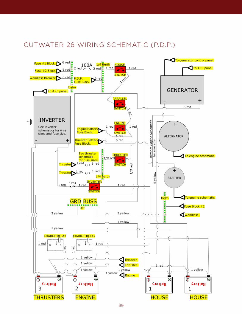
CUTWATER 26 WIRING SCHEMATIC (P.D.P.)
ALTERNATOR
100A
INVERTERSee Inverterschematics for wiresizes and fuse size.
To A.C. panel.
HOUSE HOUSETHRUSTERS ENGINE.
GENERATOR
- +
To A.C. panel.
To generator control panel.
BUSSGRD
To engine schematic.
STARTER
To engine schematic.
+-
3 2 1
+
+
2 red 1 red 1 red
1 red1 red
6 red
6 ye
llow
1 red
2 yellow
1/O red
1/O
red
1 red
1 red1 red
1 redThruster
Thruster
1 red
1 re
d
1 re
d
1 red
1 yellow 1 yellow1 yellow
1 yellow
11-25-13
Cutwater C-26 Power DistributionHOUSE
ENGINE
THRUSTER
INVERTER
PARALLEL
ELECTRICAL SCHEMATIC
See thrusterschematicfor fuse sizes.
CHARGE RELAY CHARGE RELAY
SWITCH
SWITCH
SWITCH
SWITCH
SWITCH
Thruster1 yellow
1 red
1 yellow
1 red1 red1 red 175A
Engine1 yellow
Thruster1 yellow
Engine BatteryFuse Block.
Thruster BatteryFuse Block.
6 red6 red
2 red
P.D.P.Fuse Block.
Fuse #1 Block.
6 red
Fuse #2 Block.
Wendlass Breaker.
6 red
6 red
6 red
1 red
2 yellow
Fuse Block #2
Wendlass
1/4 Berth
1/4 Berth
Aft
Helm
Helm
Ref
er to
Eng
ine
Sch
emat
ic f
or w
ire
size
1
40
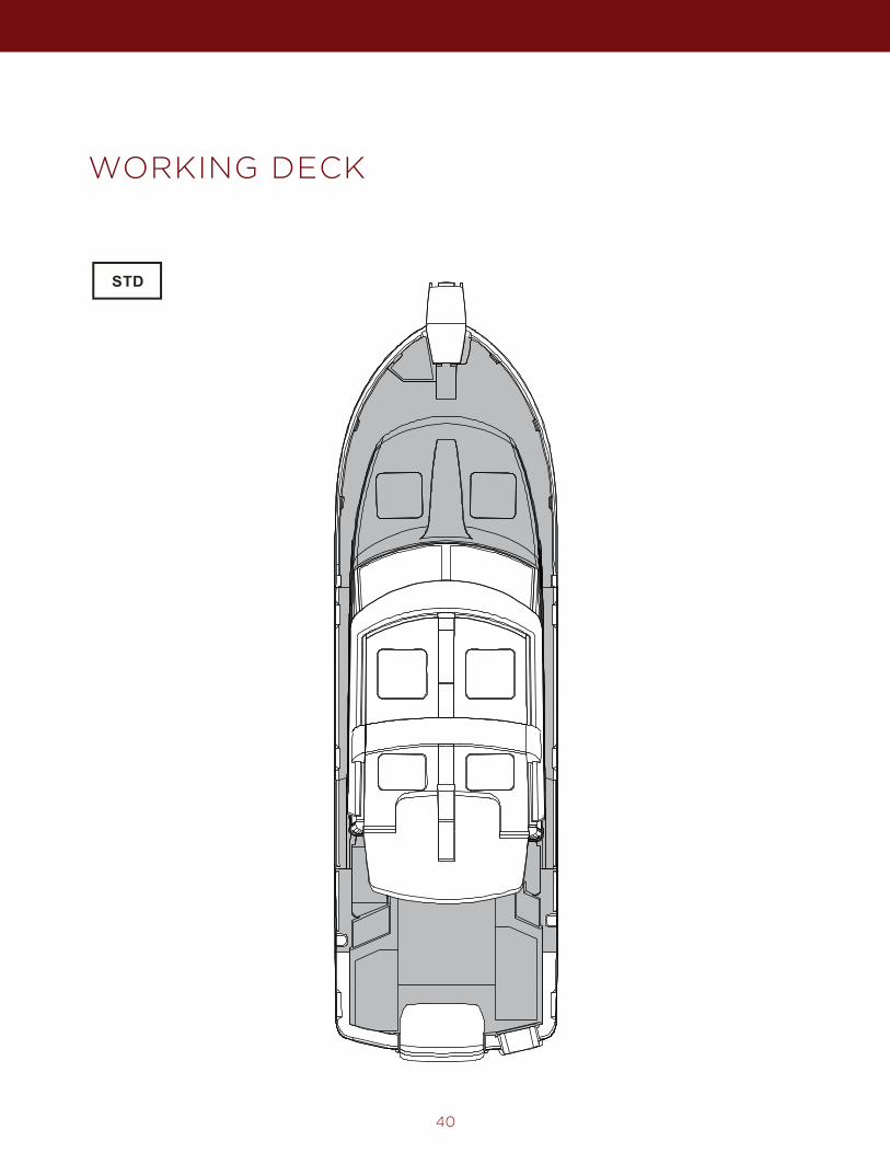
WORKING DECK
41
CARE AND MAINTENANCE
The following checklists are examples and are not all inclusive and are provided only as a guide. Please customize to your personal needs. Consult your engine and trailer user manuals for additional information.
TOW VEHICLE – PRIOR TO USE
£ Test Lights.£ Check brakes.£ Check tire pressure and condition.£ Check hitch related electrical connections.
TRAILER – PRIOR TO USE
£ Check registration£ Check rollers and bed rails.£ Check wheel bearings and lubricate as required.£ Check winch.£ Test electrical connection and lights.£ Check tire pressure and condition.£ Check safety chains.£ Check boat straps.£ Check braking system.£ Check hitch for proper connection and lock down.£ Install safety chains (cross under hitch).£ Remove tire blocks.
BOAT – PRIOR TO USE WITH TRAILER
£ Lower mast.£ Lower VHF antenna.£ Secure the Bimini awning frame.£ Raise and secure swim platform ladder.£ Set all switches and breakers to the OFF position, Including Thruster/Windlass cutoff switch£ Close and secure all windows, ports and vents.£ Lock cabin.£ Center rudder.£ Remove Drain Plug
EXAMPLE OF A PREPARATION FOR THE ROAD CHECKLIST
42
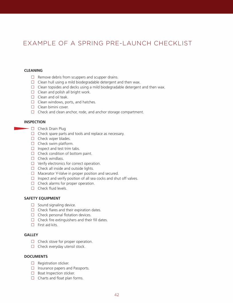
EXAMPLE OF A SPRING PRE-LAUNCH CHECKLIST
CLEANING
£ Remove debris from scuppers and scupper drains.£ Clean hull using a mild biodegradable detergent and then wax.£ Clean topsides and decks using a mild biodegradable detergent and then wax.£ Clean and polish all bright work.£ Clean and oil teak.£ Clean windows, ports, and hatches.£ Clean bimini cover.£ Check and clean anchor, rode, and anchor storage compartment.
INSPECTION
£ Check Drain Plug£ Check spare parts and tools and replace as necessary.£ Check wiper blades.£ Check swim platform.£ Inspect and test trim tabs.£ Check condition of bottom paint.£ Check windlass.£ Verify electronics for correct operation.£ Check all inside and outside lights.£ Macerator Y-Valve in proper position and secured.£ Inspect and verify position of all sea cocks and shut off valves.£ Check alarms for proper operation.£ Check fluid levels.
SAFETY EQUIPMENT
£ Sound signaling device.£ Check flares and their expiration dates.£ Check personal flotation devices.£ Check fire extinguishers and their fill dates.£ First aid kits.
GALLEY
£ Check stove for proper operation.£ Check everyday utensil stock.
DOCUMENTS
£ Registration sticker.£ Insurance papers and Passports.£ Boat Inspection sticker.£ Charts and float plan forms.
43
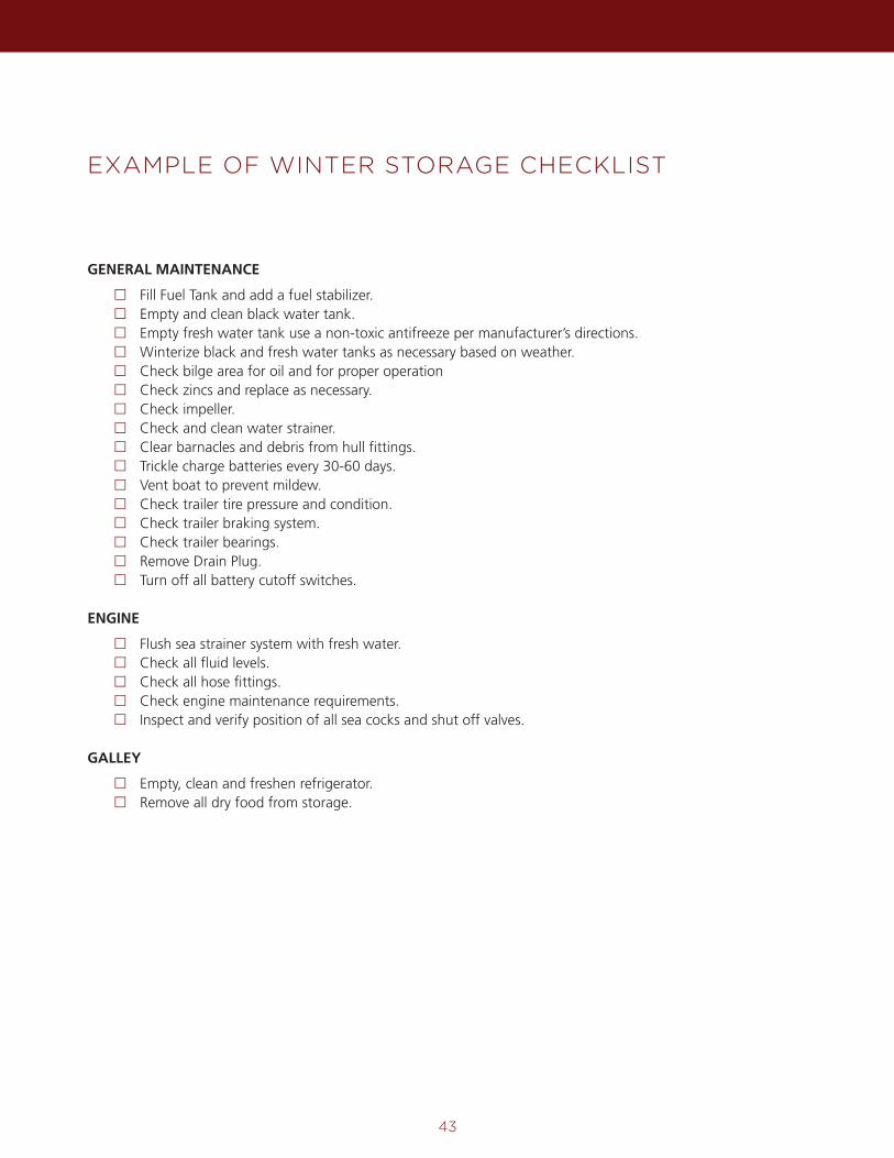
EXAMPLE OF WINTER STORAGE CHECKLIST
GENERAL MAINTENANCE
£ Fill Fuel Tank and add a fuel stabilizer.£ Empty and clean black water tank.£ Empty fresh water tank use a non-toxic antifreeze per manufacturer’s directions.£ Winterize black and fresh water tanks as necessary based on weather.£ Check bilge area for oil and for proper operation£ Check zincs and replace as necessary.£ Check impeller.£ Check and clean water strainer.£ Clear barnacles and debris from hull fittings.£ Trickle charge batteries every 30-60 days.£ Vent boat to prevent mildew.£ Check trailer tire pressure and condition.£ Check trailer braking system.£ Check trailer bearings.£ Remove Drain Plug.£ Turn off all battery cutoff switches.
ENGINE
£ Flush sea strainer system with fresh water.£ Check all fluid levels.£ Check all hose fittings.£ Check engine maintenance requirements.£ Inspect and verify position of all sea cocks and shut off valves.
GALLEY
£ Empty, clean and freshen refrigerator.£ Remove all dry food from storage.
44
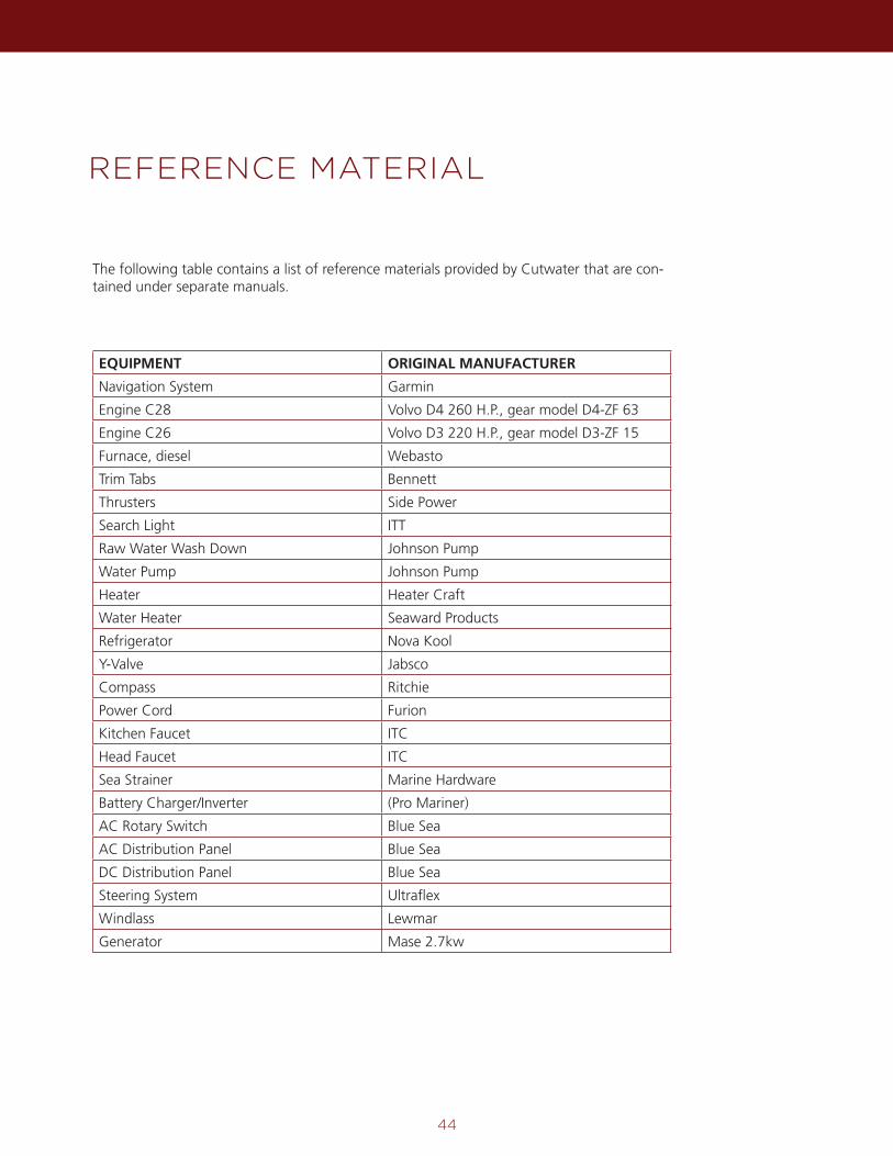
REFERENCE MATERIAL
The following table contains a list of reference materials provided by Cutwater that are con-tained under separate manuals.
EQUIPMENT ORIGINAL MANUFACTURER
Navigation System Garmin
Engine C28 Volvo D4 260 H.P., gear model D4-ZF 63
Engine C26 Volvo D3 220 H.P., gear model D3-ZF 15
Furnace, diesel Webasto
Trim Tabs Bennett
Thrusters Side Power
Search Light ITT
Raw Water Wash Down Johnson Pump
Water Pump Johnson Pump
Heater Heater Craft
Water Heater Seaward Products
Refrigerator Nova Kool
Y-Valve Jabsco
Compass Ritchie
Power Cord Furion
Kitchen Faucet ITC
Head Faucet ITC
Sea Strainer Marine Hardware
Battery Charger/Inverter (Pro Mariner)
AC Rotary Switch Blue Sea
AC Distribution Panel Blue Sea
DC Distribution Panel Blue Sea
Steering System Ultraflex
Windlass Lewmar
Generator Mase 2.7kw

45
CONTACTS
Customer Service
Andrew Custis Customer Service Manager
Phone 253-839-5213
Web Site
www.Cutwaterboats.com

46
NOTES

47
All rights reserved. Reproduction or translation by any means in whole or in part is not permitted without
written authorization from Cutwater. The information contained herein is correct to the best of Cutwater
knowledge and the contents may change without notice and without incurring obligation.

17341 Tye St. S.E Monroe, Washington 98272
Phone 800.349.7198 Fax 866.408.9516
cutwaterboats.com

![Starsin, Owners of cargo v Starsin, Owners &/or demise ... 2003.pdf · Starsin, Owners of cargo v Starsin, Owners &/or demise charterers [2003] APP.L.R. 03/13 ... owners under these](https://img.pdfslide.us/doc/110x75/5b34b4ba7f8b9aa0238e4fb6/starsin-owners-of-cargo-v-starsin-owners-or-demise-2003pdf-starsin.jpg)