Embed Size (px)
Citation preview
American Institute of Aeronautics and Astronautics
1
Cutting More Than Metal: Breaking through the
Development Cycle
Christopher E. Singer1 and Jay Onken
2
NASA Marshall Space Flight Center, Huntsville, AL 25812
NASA is advancing a new development approach and new technologies in the design,
construction, and testing of the next great launch vehicle for space exploration. The ability to
use these new tools is made possible by a learning culture able to embrace innovation,
flexibility, and prudent risk tolerance, while retaining the hard-won lessons learned through
the successes and failures of the past. This paper provides an overview of the Marshall Space
Flight Center’s new approach to launch vehicle development, as well as examples of how
that approach has been leveraged by NASA’s Space Launch System (SLS) Program to
achieve its key goals of safety, affordability, and sustainability.
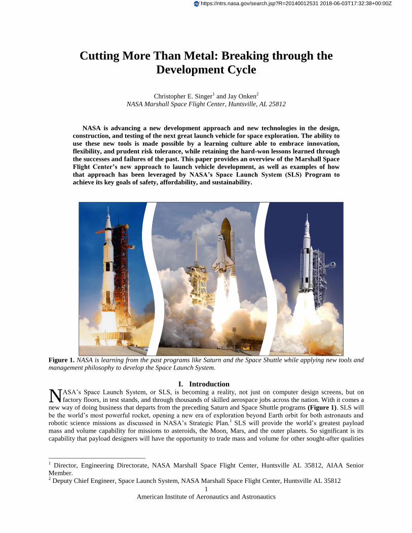
Figure 1. NASA is learning from the past programs like Saturn and the Space Shuttle while applying new tools and
management philosophy to develop the Space Launch System.
I. Introduction ASA’s Space Launch System, or SLS, is becoming a reality, not just on computer design screens, but on
factory floors, in test stands, and through thousands of skilled aerospace jobs across the nation. With it comes a
new way of doing business that departs from the preceding Saturn and Space Shuttle programs (Figure 1). SLS will
be the world’s most powerful rocket, opening a new era of exploration beyond Earth orbit for both astronauts and
robotic science missions as discussed in NASA’s Strategic Plan.1 SLS will provide the world’s greatest payload
mass and volume capability for missions to asteroids, the Moon, Mars, and the outer planets. So significant is its
capability that payload designers will have the opportunity to trade mass and volume for other sought-after qualities
1 Director, Engineering Directorate, NASA Marshall Space Flight Center, Huntsville AL 35812, AIAA Senior
Member. 2 Deputy Chief Engineer, Space Launch System, NASA Marshall Space Flight Center, Huntsville AL 35812
N
https://ntrs.nasa.gov/search.jsp?R=20140012531 2018-06-03T17:32:38+00:00Z
American Institute of Aeronautics and Astronautics
2
such as hardware and mission simplicity, technology development cost, and reduced trip times, depending on
mission and architecture needs.
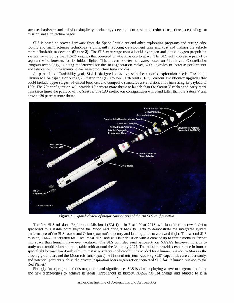
SLS is based on proven hardware from the Space Shuttle era and other exploration programs and cutting-edge
tooling and manufacturing technology, significantly reducing development time and cost and making the vehicle
more affordable to develop (Figure 2). The SLS core stage uses a liquid hydrogen and liquid oxygen propulsion
system, powered by four RS-25 engines that powered Shuttle missions to space. The SLS will also use a pair of 5-
segment solid boosters for its initial flights. This proven booster hardware, based on Shuttle and Constellation
Program technology, is being modernized for this next-generation rocket, with upgrades to increase performance
and fabrication improvements to decrease production time and cost.
As part of its affordability goal, SLS is designed to evolve with the nation’s exploration needs. The initial
version will be capable of putting 70 metric tons (t) into low Earth orbit (LEO). Various evolutionary upgrades that
could include upper stages, advanced boosters, and composite structures are envisioned for increasing its payload to
130t. The 70t configuration will provide 10 percent more thrust at launch than the Saturn V rocket and carry more
than three times the payload of the Shuttle. The 130-metric-ton configuration will stand taller than the Saturn V and
provide 20 percent more thrust.
Figure 2. Expanded view of major components of the 70t SLS configuration.
The first SLS mission – Exploration Mission 1 (EM-1) – in Fiscal Year 2018, will launch an uncrewed Orion
spacecraft to a stable point beyond the Moon and bring it back to Earth to demonstrate the integrated system
performance of the SLS rocket and Orion spacecraft’s reentry and landing prior to a crewed flight. The second SLS
mission, EM-2, is targeted for Fiscal Year 2021 and will launch Orion with a crew of up to four astronauts farther
into space than humans have ever ventured. The SLS will also send astronauts on NASA's first-ever mission to
study an asteroid relocated to a stable orbit around the Moon by 2025. The mission provides experience in human
spaceflight beyond low-Earth orbit, to test new systems and capabilities needed for a human mission to Mars in the
proving ground around the Moon (cis-lunar space). Additional missions requiring SLS’ capabilities are under study,
and potential partners such as the private Inspiration Mars organization requested SLS for its human mission to the
Red Planet.2
Fittingly for a program of this magnitude and significance, SLS is also employing a new management culture
and new technologies to achieve its goals. Throughout its history, NASA has led change and adapted to it in
American Institute of Aeronautics and Astronautics
3
response to shifting missions, budgets, technology, and major events. Nonetheless, the Apollo Program and its
design process set a standard for NASA’s development life cycle and systems engineering for decades.3 It was a
touchstone, a source of national pride, and a blueprint for mission success for succeeding generations of engineers.
But the Apollo Saturn V design cycle after 50-plus years of space transportation operations no longer directly
applies to today’s programs existing in a different society with different technologies.
Though sometimes forgotten, the reality was that the 1960s Moon program was the beneficiary of Cold War
politics, generous budgets, and a benign media environment that mitigated the impact of major failures, close calls,
and a design process that allowed for early failures. Apollo’s successor, the Space Shuttle Program, had to operate
with the greater expectations that came from Apollo’s success in a much more constrained budget climate with less
political support. The Shuttle became a great achievement, advancing space technology, computer tools, and
spaceflight operations over its 30-year lifespan. Despite the emergence of new computer-based analytical tools and
the great experience base with traditional tools, risk margins turned into risk aversion and intolerance, not only
within the Shuttle’s operational culture but also within other development programs during the Shuttle era.
Decisions took too long. Processes, reviews, and working groups proliferated. Technical aspects were disconnected
from cost and schedule. Subsystems were stovepiped. “Analysis paralysis” grew. Development schedules lagged.
The Mars Climate Orbiter and Mars Polar Lander failures increased conservatism. “Failure is not an option” became
failure to finish. Programs like X-33, X-34, Orbital Space Plane, and others were cancelled before they got to
preliminary design review (PDR).
Today, NASA is pursuing a new path for human exploration beyond Earth orbit and a new design philosophy.
SLS is key to that path. This super heavy lift capability can change the rules of exploration. But engineers face
challenges unlike those of previous eras. Economic realities are even harsher. Affordability is paramount.
International participation is a consideration. Entrepreneurial space companies are now part of that path, bringing
modern commercial processes and values. “Failure is not an option” means something different than it did during
NASA’s Apollo 13 “successful failure.”
Facing enormous opportunity and enormous challenge, NASA is examining its culture of absolute perfection and
extreme risk aversion to continue its historic mission of exploration and discovery. NASA Administrator Charles
Bolden has turned two mishaps in the past year into opportunities to talk about the importance of taking risks.
“When you do stuff that nobody else has ever done, you have to be willing to accept risk,” he said in an email to
employees after the failure of an experimental robotic lander.4 “Put another way, risk intolerance is a guarantee of
failure to accomplish anything of significance. As we prepare to undertake the many challenges offered in the
President’s 2014 budget for our agency, I ask you to continue to think about how we can identify and seize
opportunities to make progress quickly and affordably, identify and manage risks, learn fast and adapt our plans to
take the next steps. While we do this, we must constantly balance our risks and rewards and always, always put the
lives and safety of our people first.”
Again, after a spacewalk during which water began leaking into an astronaut’s spacesuit helmet, Bolden emailed
employees, noting the importance of understanding or mitigating the causes of anomalies.
“Our work both in-house and with our industry and commercial partners should entail diligence in assessing risk
and commitment to ensuring mission safety,” he said. “As the person ultimately responsible for all we do as the
NASA family, I implore you to welcome risks, because that is how we push the boundaries of our achievement, but
at the same time, I must emphasize in the strongest terms that we must not be complacent in our quest to ensure the
safety of our crew members and teams on the ground.”* These statements were communicated across the leadership
and workforce at NASA.
Today, enabled by a culture learning to embrace innovation and risk tolerance, the SLS team is using technology
and evolving program management and systems engineering processes to appropriately alter the development life
cycle, from design and analysis, through production, verification, logistics, and operations. New fabrication
techniques, verification techniques, integrated analysis, and expanding computer aided design (CAD) technologies
that follow the hardware from initial concept through operation are reducing the cost and time of bringing new
hardware to the launch pad. Cultural changes and evolved systems engineering processes and policy are becoming
more flexible, reversing a trend over the past 20 years and making it possible to take full advantage of new
techniques and approaches. These cultural and technical changes, informed by historical experience, are finding
their way into the SLS Program product development life cycle. The following sections will discuss some of those
changes.
* Message from the Administrator, “Spacewalk Mishap Investigation Board Report,” February 26, 2014.

American Institute of Aeronautics and Astronautics
4
II. Cultural Change
Evolving and accelerating the design cycle requires cultural change. In pursuit of its affordability goals, SLS
employed workforce alignment, integrated acquisition teams, facility consolidation, streamlined configuration
management and requirements, and applied value stream mapping and industry best practices, in addition to
further integrating traditional tools such as computer aided design.
The SLS team also took a look at the general condition. There is a greater understanding of the hardware life
cycle and the appropriate balance points in that cycle for innovation and risk tolerance versus process and control as
the program progresses from the drawing board to the launch pad (Figure 3). There’s a greater emphasis on finding
solutions vs. policy compliance, the need to adjust to program/project size, the importance of integration and
communication, and the focus on the product and people over the process.
Figure 3. Development culture vs. operational culture.
After years of debating the intense level of insight and oversight into its programs, a hybrid development and
acquisition model based on risk deliberately evolved during SLS formulation. The goal was to hit a balance between
insight and oversight to be affordable and sustainable. The team sought to identify and resolve issues and establish
clear requirements and simple lines of accountability early in the Program and employ existing and emerging
technologies to reduce risk. The new model relies on government and industry best practices and lessons lived,
balancing flexibility and innovation with appropriate discipline and rigor. Integration and simple interfaces between
NASA and industry team members promotes effective communication. The Program reduced the number of
deliverable documents required. SLS accepts formats and applications used by contractors in return for access to
contractor systems. The number of Government specifications and standards has been reduced. Contractor and
industry specifications and standards are accepted to the extent possible. These and other adaptations by the SLS
team have kept the Program on schedule and within budget.
III. Technology Impacts on the Design Cycle To thrive in the current economic climate, SLS employs creative engineering that retains the appropriate rigor
and accepts appropriate flexibility. Designers now accept methods such as parametric analysis without extensive,
expensive testing that affects budget and schedule, taking full advantage of experience and knowledge gained from
heritage programs.
The way SLS employs new technology – often in combination with traditional technology – varies based on the
size, complexity, allowable risk, cost, schedule, and other factors. Techniques pioneered on the Space Shuttle such
as friction stir welding, are being used on the Core Stage to reduce costs and manufacturing time and increase
American Institute of Aeronautics and Astronautics
5
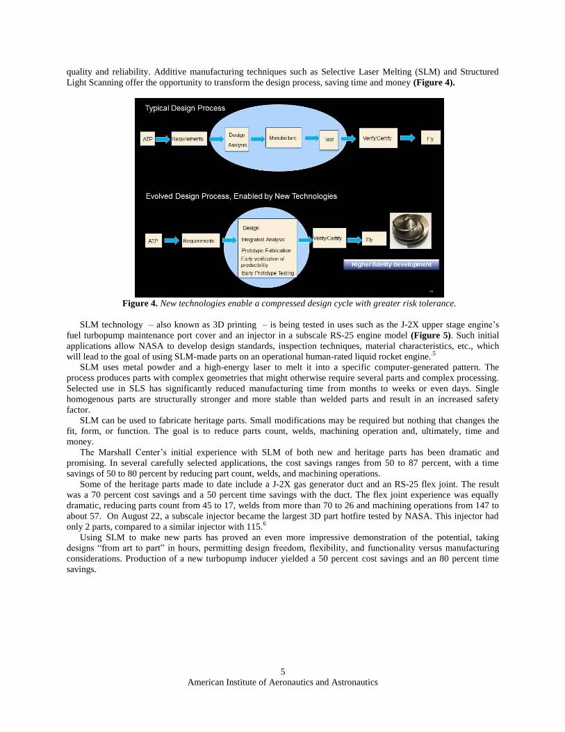
quality and reliability. Additive manufacturing techniques such as Selective Laser Melting (SLM) and Structured
Light Scanning offer the opportunity to transform the design process, saving time and money (Figure 4).
Figure 4. New technologies enable a compressed design cycle with greater risk tolerance.
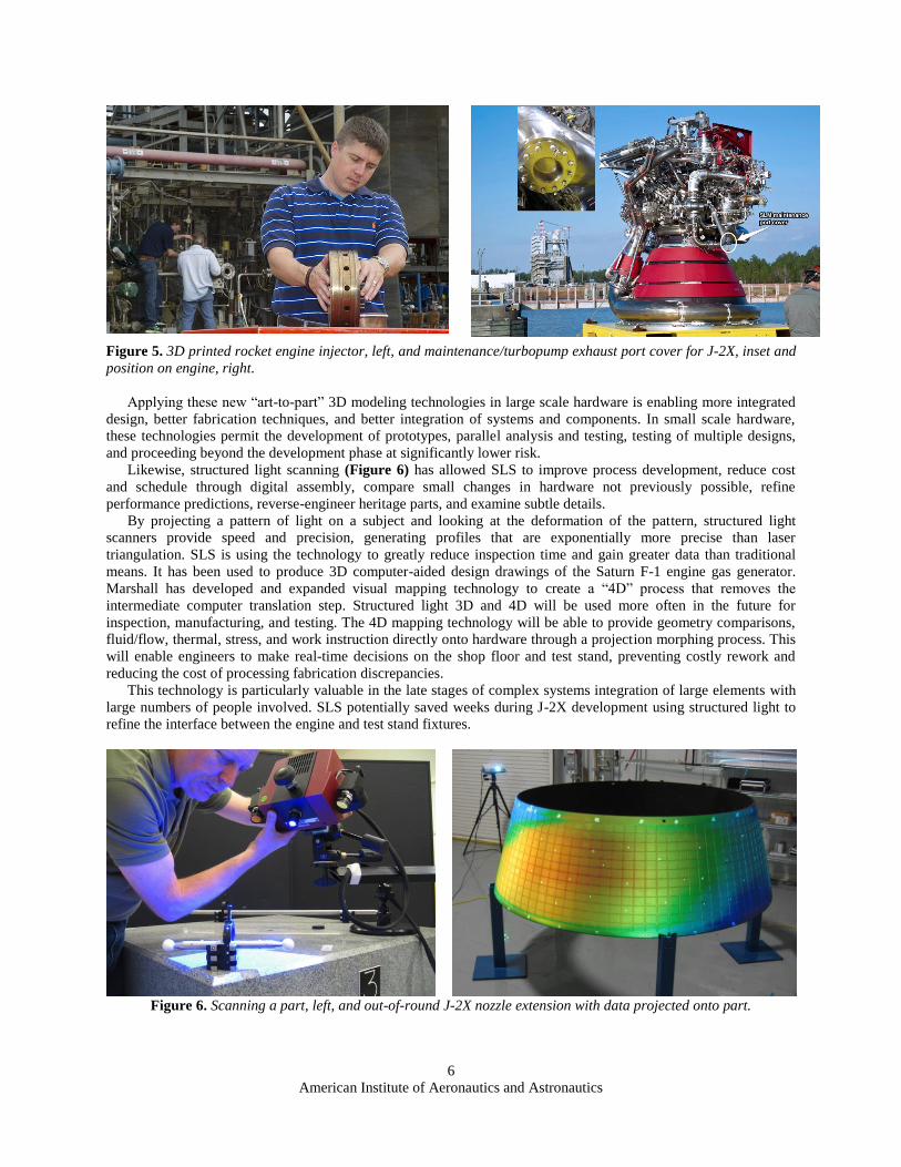
SLM technology – also known as 3D printing – is being tested in uses such as the J-2X upper stage engine’s
fuel turbopump maintenance port cover and an injector in a subscale RS-25 engine model (Figure 5). Such initial
applications allow NASA to develop design standards, inspection techniques, material characteristics, etc., which
will lead to the goal of using SLM-made parts on an operational human-rated liquid rocket engine..5
SLM uses metal powder and a high-energy laser to melt it into a specific computer-generated pattern. The
process produces parts with complex geometries that might otherwise require several parts and complex processing.
Selected use in SLS has significantly reduced manufacturing time from months to weeks or even days. Single
homogenous parts are structurally stronger and more stable than welded parts and result in an increased safety
factor.
SLM can be used to fabricate heritage parts. Small modifications may be required but nothing that changes the
fit, form, or function. The goal is to reduce parts count, welds, machining operation and, ultimately, time and
money.
The Marshall Center’s initial experience with SLM of both new and heritage parts has been dramatic and
promising. In several carefully selected applications, the cost savings ranges from 50 to 87 percent, with a time
savings of 50 to 80 percent by reducing part count, welds, and machining operations.
Some of the heritage parts made to date include a J-2X gas generator duct and an RS-25 flex joint. The result
was a 70 percent cost savings and a 50 percent time savings with the duct. The flex joint experience was equally
dramatic, reducing parts count from 45 to 17, welds from more than 70 to 26 and machining operations from 147 to
about 57. On August 22, a subscale injector became the largest 3D part hotfire tested by NASA. This injector had
only 2 parts, compared to a similar injector with 115.6
Using SLM to make new parts has proved an even more impressive demonstration of the potential, taking
designs “from art to part” in hours, permitting design freedom, flexibility, and functionality versus manufacturing
considerations. Production of a new turbopump inducer yielded a 50 percent cost savings and an 80 percent time
savings.
American Institute of Aeronautics and Astronautics
6
Figure 5. 3D printed rocket engine injector, left, and maintenance/turbopump exhaust port cover for J-2X, inset and
position on engine, right.
Applying these new “art-to-part” 3D modeling technologies in large scale hardware is enabling more integrated
design, better fabrication techniques, and better integration of systems and components. In small scale hardware,
these technologies permit the development of prototypes, parallel analysis and testing, testing of multiple designs,
and proceeding beyond the development phase at significantly lower risk.
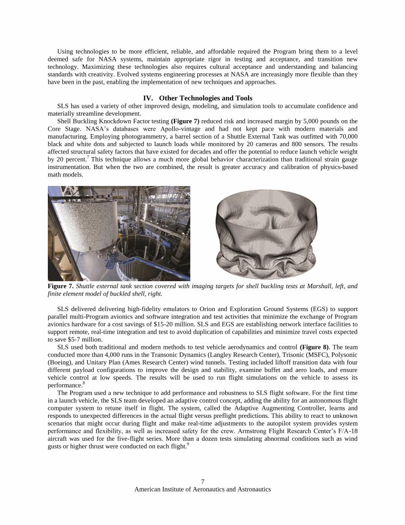
Likewise, structured light scanning (Figure 6) has allowed SLS to improve process development, reduce cost
and schedule through digital assembly, compare small changes in hardware not previously possible, refine
performance predictions, reverse-engineer heritage parts, and examine subtle details.
By projecting a pattern of light on a subject and looking at the deformation of the pattern, structured light
scanners provide speed and precision, generating profiles that are exponentially more precise than laser
triangulation. SLS is using the technology to greatly reduce inspection time and gain greater data than traditional
means. It has been used to produce 3D computer-aided design drawings of the Saturn F-1 engine gas generator.
Marshall has developed and expanded visual mapping technology to create a “4D” process that removes the
intermediate computer translation step. Structured light 3D and 4D will be used more often in the future for
inspection, manufacturing, and testing. The 4D mapping technology will be able to provide geometry comparisons,
fluid/flow, thermal, stress, and work instruction directly onto hardware through a projection morphing process. This
will enable engineers to make real-time decisions on the shop floor and test stand, preventing costly rework and
reducing the cost of processing fabrication discrepancies.
This technology is particularly valuable in the late stages of complex systems integration of large elements with
large numbers of people involved. SLS potentially saved weeks during J-2X development using structured light to
refine the interface between the engine and test stand fixtures.
Figure 6. Scanning a part, left, and out-of-round J-2X nozzle extension with data projected onto part.
American Institute of Aeronautics and Astronautics
7
Using technologies to be more efficient, reliable, and affordable required the Program bring them to a level
deemed safe for NASA systems, maintain appropriate rigor in testing and acceptance, and transition new
technology. Maximizing these technologies also requires cultural acceptance and understanding and balancing
standards with creativity. Evolved systems engineering processes at NASA are increasingly more flexible than they
have been in the past, enabling the implementation of new techniques and approaches.
IV. Other Technologies and Tools SLS has used a variety of other improved design, modeling, and simulation tools to accumulate confidence and
materially streamline development.
Shell Buckling Knockdown Factor testing (Figure 7) reduced risk and increased margin by 5,000 pounds on the
Core Stage. NASA’s databases were Apollo-vintage and had not kept pace with modern materials and
manufacturing. Employing photogrammetry, a barrel section of a Shuttle External Tank was outfitted with 70,000
black and white dots and subjected to launch loads while monitored by 20 cameras and 800 sensors. The results
affected structural safety factors that have existed for decades and offer the potential to reduce launch vehicle weight
by 20 percent.7
This technique allows a much more global behavior characterization than traditional strain gauge
instrumentation. But when the two are combined, the result is greater accuracy and calibration of physics-based
math models.
Figure 7. Shuttle external tank section covered with imaging targets for shell buckling tests at Marshall, left, and
finite element model of buckled shell, right.
SLS delivered delivering high-fidelity emulators to Orion and Exploration Ground Systems (EGS) to support
parallel multi-Program avionics and software integration and test activities that minimize the exchange of Program
avionics hardware for a cost savings of $15-20 million. SLS and EGS are establishing network interface facilities to
support remote, real-time integration and test to avoid duplication of capabilities and minimize travel costs expected
to save $5-7 million.
SLS used both traditional and modern methods to test vehicle aerodynamics and control (Figure 8). The team
conducted more than 4,000 runs in the Transonic Dynamics (Langley Research Center), Trisonic (MSFC), Polysonic
(Boeing), and Unitary Plan (Ames Research Center) wind tunnels. Testing included liftoff transition data with four
different payload configurations to improve the design and stability, examine buffet and aero loads, and ensure
vehicle control at low speeds. The results will be used to run flight simulations on the vehicle to assess its
performance.8
The Program used a new technique to add performance and robustness to SLS flight software. For the first time
in a launch vehicle, the SLS team developed an adaptive control concept, adding the ability for an autonomous flight
computer system to retune itself in flight. The system, called the Adaptive Augmenting Controller, learns and
responds to unexpected differences in the actual flight versus preflight predictions. This ability to react to unknown
scenarios that might occur during flight and make real-time adjustments to the autopilot system provides system
performance and flexibility, as well as increased safety for the crew. Armstrong Flight Research Center’s F/A-18
aircraft was used for the five-flight series. More than a dozen tests simulating abnormal conditions such as wind
gusts or higher thrust were conducted on each flight.9

American Institute of Aeronautics and Astronautics
8
Figure 8. Wind tunnel testing at Ames Research Center, left, and Armstrong Flight Research Center, right.
SLS hardware, software, and operating systems were brought together in 2014 in the System Integration Test
Facility to fly SLS virtually the way it will fly in reality (Figure 9). Avionics hardware was arranged in an
instrument ring flight configuration, including the most powerful computer processor every used on a flight system.
Tests will tell designers how the vehicle will perform from the launch pad to space under a variety of conditions.10
Figure 9. Boeing workers install SLS avionics, left. A test engineer runs flight simulation, right.
V. Program Benefits There are numerous indications that new tools and new rules/acceptance for using them are taking hold and
changing the design process. SLS benefits from a streamlined organization with more than 50 percent reduction in
civil service workforce and more than 30 percent in non-prime contractors compared to the Constellation Program.
This enabled a quicker start and flexibility not available under traditional contract methods. Breaking with recent
history of large prime System Engineering & Integration (SE&I) contracts, SLS performs that function in-house at
Marshall using a streamlined organizational structure focused on communication, integration and accountability.
Combined with fewer governance boards, the result is increased decisional velocity and earlier identification and
resolution of issues. The SE&I team worked numerous actions in 2013 to understand vehicle performance, work out
interface issues between vehicle elements, coordinate overall vehicle design issues, and complete other tasks critical
to supporting streamlined development.
A significant amount of highly detailed vehicle-level analyses were conducted to ensure that preliminary design
met requirements. Integrated vehicle design tools were used to assess the health of the vehicle against requirements.
Each major assembly used value stream mapping and producability analysis, making sure design and manufacturing
were in sync for tooling interfaces.
SLS booster manufacturer ATK used value stream mapping to achieve a 46 percent reduction in manufacturing
and assembly time. The company also implemented new non-destructive evaluation techniques. Teams identified
more than 300 changes and eliminated more than 400 hardware moves. Similar efforts by Aerojet Rocketdyne are
targeting RS-25 production cost reductions of up to 30 percent on powerhead and nozzle components. Also within
the Liquid Engines project, systems engineering and affordability thinking led to development of a common engine
controller that will work for several engines, reducing hardware development and cost.

American Institute of Aeronautics and Astronautics
9
In the Core Stage effort, the Program’s only new development component, manufacturing tooling was in place at
Michoud Assembly Facility (MAF)11
and producing full-size test hardware (Figure 10).
Figure 10. Core Stage barrel segment, left and dome segment, right, at Michoud Assembly Facility.
The J-2X Upper Stage Engine borrowed its operating cycle and flow schematic from the Apollo-heritage J-2
engine but was otherwise virtually a new propulsion system with improved power level and performance. Yet it
reached 100 percent power level on the test stand in just 29 days compared to 651 days for the J-2. While the
government/industry team’s decades of experience deserves recognition, the ability to integrate modern design,
analysis, and test practices contributed to the success of the Design, Development, Test, and Evaluation (DT&E)
effort. With completion of the J-2X test series, the government/industry team is transferring its experience to the
core stage engine project.
Using improved models and tools developed since the Shuttle, SLS has decided to conduct integrated systems
test (green run) of the first core stage flight article rather than building a separate main propulsion test article
(MPTA), saving hundreds of millions of dollars.
Such efforts to adopt new technologies and practices have had a significant cumulative effect. SLS reached
System Requirements Review/Systems Design Review milestones in only 10 months from Program announcement
and Preliminary Design Review less than 2 years from the SLS architecture announcement in 2011.12
SLS is now
more than halfway through design and development. Element Critical Design Reviews (CDR) are ongoing
throughout 2014, with the vehicle CDR scheduled for 2015. Notably, in the current economic climate, SLS is on
schedule and within budget to deliver the most capable launch vehicle in history for launch availability in FY 2018.
Again, there are many reasons for that success, but the new tools and the SLS team’s ability to use them played a
significant role.
American Institute of Aeronautics and Astronautics
10
Figure 11. Milestones in the SLS development path, on track to support launch in FY2018.
VI. Conclusion Over the years, NASA has evolved slowly from an Apollo-era design cycle, knowledge, experience, technology,
and external factors rapidly changed around it. Experience now suggests that there is another way. In addition to
lessons learned, the SLS team has an increasingly sophisticated set of testing, tools, and techniques for reducing risk.
New technologies are changing the way NASA does business, including the design process. Developing new
technology and pushing its limits is essential to achieving Agency and SLS programmatic goals while reflecting the
key tenants of safety, affordability, and sustainability. NASA engineers increasingly understand that development
requires a different approach than operations. In development, engineers need to be more innovative, flexible, and
risk tolerant. In operations, the launch vehicle professionals can afford to be more aligned with process and control.
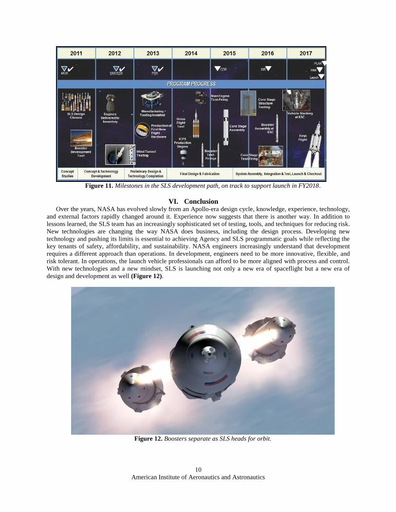
With new technologies and a new mindset, SLS is launching not only a new era of spaceflight but a new era of
design and development as well (Figure 12).
Figure 12. Boosters separate as SLS heads for orbit.
American Institute of Aeronautics and Astronautics
11
References 1NASA Strategic Plan 2014, URL: http://www.nasa.gov/sites/default/files/files/FY2014_NASA_SP_508c.pdf.
2 Coppinger, Rob, “NASA’s huge SLS Rocket Could Power Missions Far Beyond Mars,” NBCnews.com, URL:
http://www.nbcnews.com/id/49610066/ns/technology_and_science-space/t/nasas-huge-sls-rocket-could-power-mission-far-
beyond-mars/ [30 October 2012]. 3Johnson, Stephen B, The Secret of Apollo: Systems Management in American and European Space Programs, Johns
Hopkins University Press, 2002. 4
Bolden, Charles, “Message from the Administrator NASA and the Importance of Risk,” SPACEREF.com, April 19, 2013,
URL: http://spaceref.com/news/viewsr.html?pid=43870. 5
“3D Printers to Build NASA’s Spare Parts & Rocket Engines,” Popular Mechanics, URL: 3d-printers-to-build-nasas-spare-
parts-rocket-engines-15146569 [26 February 2013] 6”3D printing helps NASA make headway on the Space Launch System,” 3dprinter.net, URL: http://www.3dprinter.net/3d-
printing-helps-nasa-make-headway-on-the-space-launch-system [July 31, 2013]. 7”NASA Engineers Crush Fuel Tank to Build Better Rockets,” nasa.gov, URL:
http://www.nasa.gov/exploration/systems/sls/shell-buckling-completed.html [17 December 2013]. 8”Wind Tunnel Testing Used to Understand the Unsteady Side of Aerodynamics,” nasa.gov, URL:
http://www.nasa.gov/exploration/systems/sls/sls-aerodynamics.html [4 November, 2013]. 9”NASA F/A-18 Hornets Conduct Vital Testing for SLS Flight Control System,” AmericaSpace.com, URL:
http://www.americaspace.com/?p=45508 [21 November 2013]. 10
”SLS Avionics System Sees the (First) Light,” nasa.gov, URL: http://www.nasa.gov/exploration/systems/sls/testing-sls-
avionics.html [9 January 2014]. 11
”At Michoud, NASA Hits Milestone in Space Launch System, Unveils Rocket Segment,” The Times-Picayune, URL:
http://www.nola.com/business/index.ssf/2013/08/nasa_space_rocket_michoud_asse.html [1 August 2013]. 12
”NASA Heavy Lifter Passes Preliminary Design Review,” Aviation Week, URL: http://aviationweek.com/space/nasa-
heavy-lifter-passes-preliminary-design-review [21 December 2012].