Embed Size (px)
Citation preview
0
© WZL/Fraunhofer IPT
Cutting materials, tools and coolants
for machining with geometrically
defined cutting edges – part 1
Manufacturing Technology I
Lecture 4
Laboratory for Machine Tools and Production Engineering
Chair of Manufacturing Technology
Prof. Dr.-Ing. Dr.-Ing. E.h. F. Klocke
1
Seite 1© WZL/Fraunhofer IPT
Contents of the lectures 4 and 5
� tool steels
� cemented carbides
� coatings
� ceramics
� tool design
� cooling lubricants
� Lecture 4
� Lecture 5
2
Seite 2© WZL/Fraunhofer IPT
Structure
� Introduction
– classification according to hardness and toughness
– nomenclature and classification of cutting materials
Tool steels
Cemented carbides
Coatings
Summary
3
Seite 3© WZL/Fraunhofer IPT
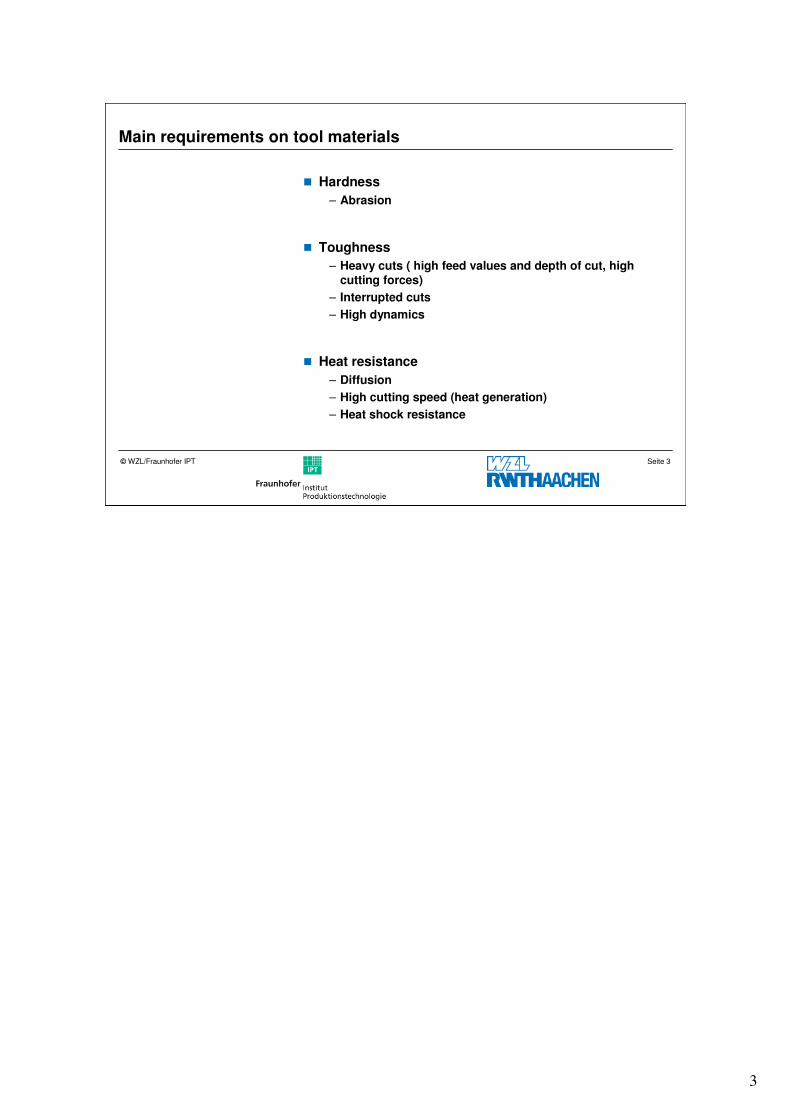
Main requirements on tool materials
� Hardness
– Abrasion
� Toughness
– Heavy cuts ( high feed values and depth of cut, high cutting forces)
– Interrupted cuts
– High dynamics
� Heat resistance
– Diffusion
– High cutting speed (heat generation)
– Heat shock resistance
4
Seite 4© WZL/Fraunhofer IPT
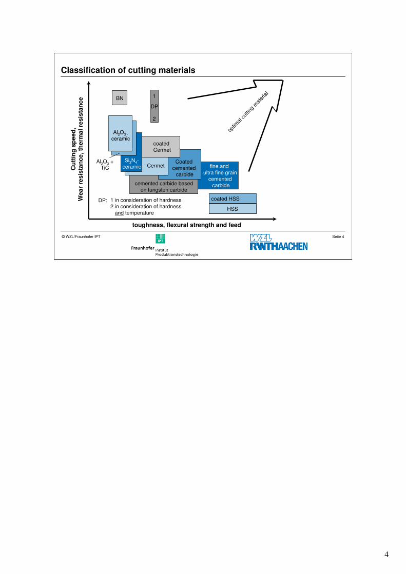
Classification of cutting materials
toughness, flexural strength and feed
Cu
ttin
g s
pe
ed
,W
ea
r re
sis
tan
ce
, th
erm
al
resis
tan
ce
DP
optim
al cut
ting
mat
erial
1BN
1 in consideration of hardness2 in consideration of hardness
and temperature
DP:
2
fine and ultra fine grain
cementedcarbide
Al2O3 + TiC Cermet
coatedCermet
Coated cemented
carbide
Si3N4-ceramic
Al2O3 -
ceramic
cemented carbide basedon tungsten carbide
coated HSS
HSS
5
Seite 5© WZL/Fraunhofer IPT
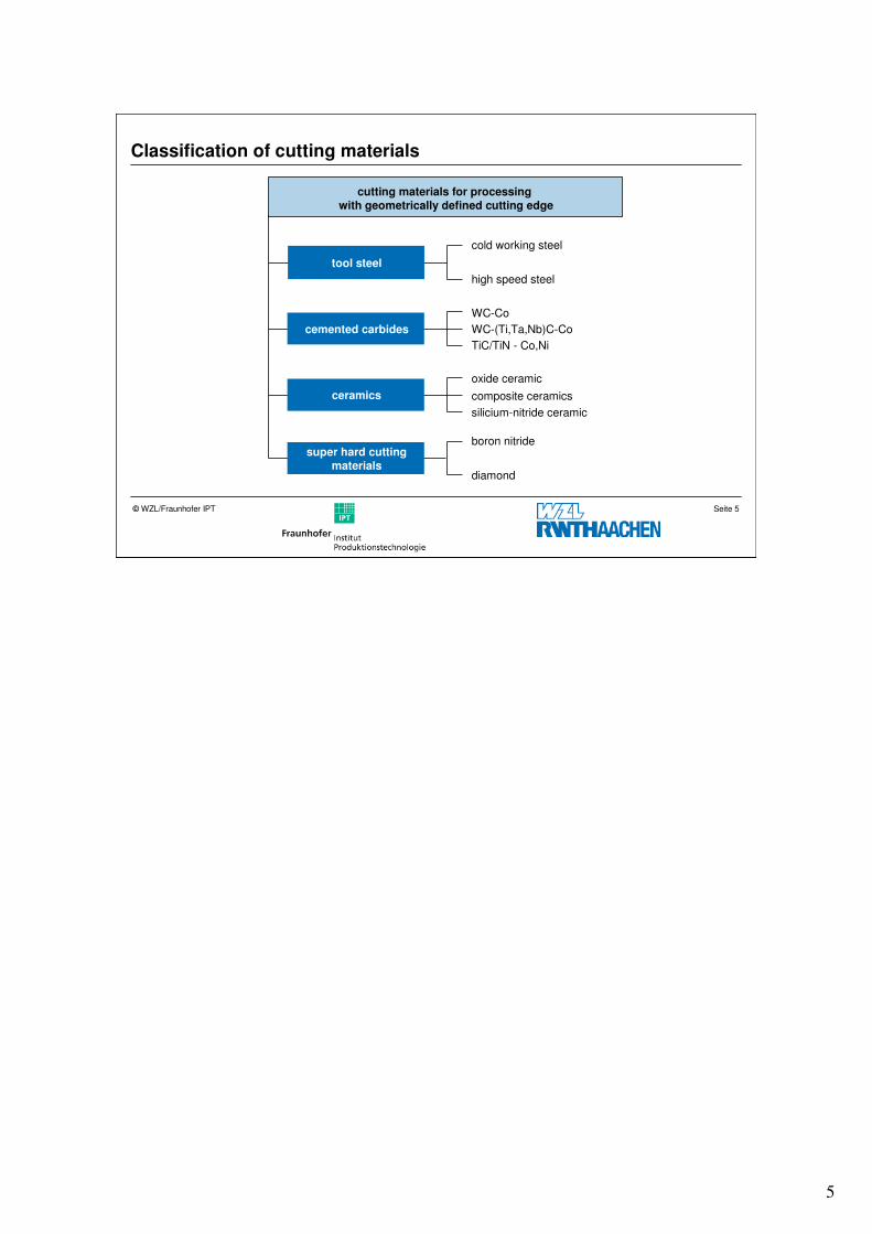
Classification of cutting materials
cold working steel
high speed steel
WC-Co
TiC/TiN - Co,Ni
WC-(Ti,Ta,Nb)C-Co
oxide ceramic
silicium-nitride ceramic
composite ceramics
boron nitride
diamond
tool steel
cemented carbides
ceramics
super hard cuttingmaterials
cutting materials for processing with geometrically defined cutting edge
6
Seite 6© WZL/Fraunhofer IPT
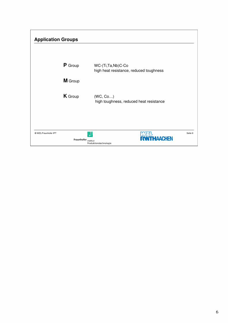
Application Groups
P Group WC-(Ti,Ta,Nb)C-Co
high heat resistance, reduced toughness
M Group
K Group (WC, Co…)
high toughness, reduced heat resistance
7
Seite 7© WZL/Fraunhofer IPT
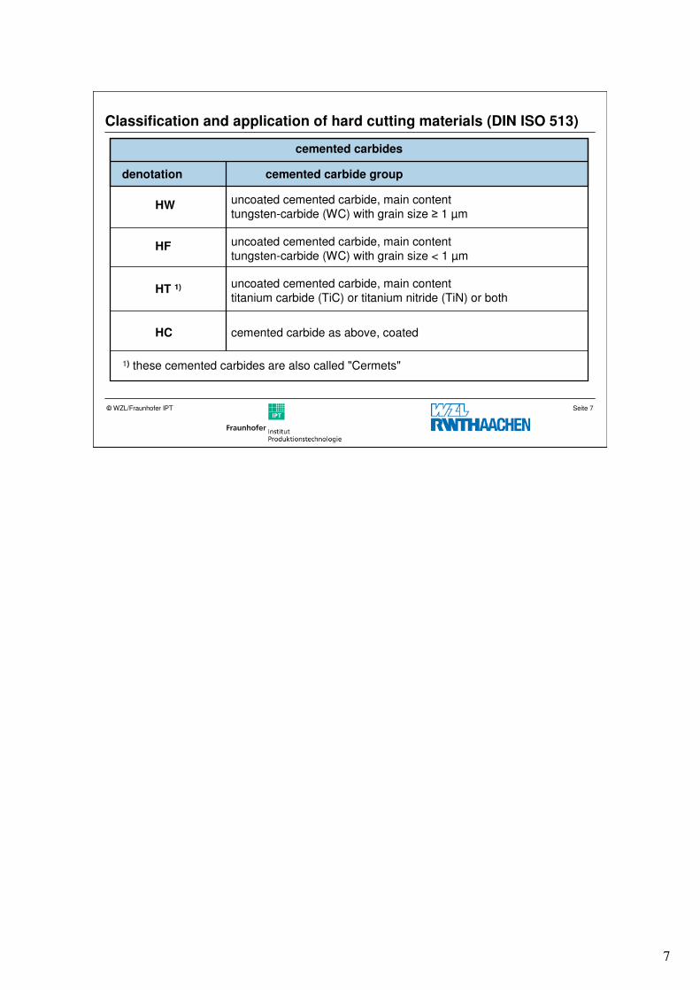
cemented carbides
denotation cemented carbide group
HW uncoated cemented carbide, main content tungsten-carbide (WC) with grain size ≥ 1 µm
HT 1) uncoated cemented carbide, main content titanium carbide (TiC) or titanium nitride (TiN) or both
HC cemented carbide as above, coated
1) these cemented carbides are also called "Cermets"
HF uncoated cemented carbide, main content tungsten-carbide (WC) with grain size < 1 µm
Classification and application of hard cutting materials (DIN ISO 513)
8
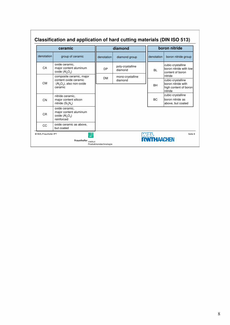
Seite 8© WZL/Fraunhofer IPT
Classification and application of hard cutting materials (DIN ISO 513)
ceramic
denotation group of ceramic
CAoxide ceramic,major content aluminum oxide (Al2O3)
CM
composite ceramic, major content oxide ceramic(Al2O3), also non-oxide ceramic
CN
nitride ceramic, major content silicon nitride (Si3N4)
CR
oxide ceramic,major content aluminum oxide (Al2O3)
reinforced
CC oxide ceramic as above, but coated
diamond
denotation diamond group
DPpoly-crystalline diamond
DMmono-crystalline diamond
boron nitride
denotation boron nitride group
BL
cubic-crystalline boron nitride with low content of boron nitride
BH
BC
cubic-crystalline boron nitride with high content of boron nitride
cubic-crystalline
boron nitride as
above, but coated
9
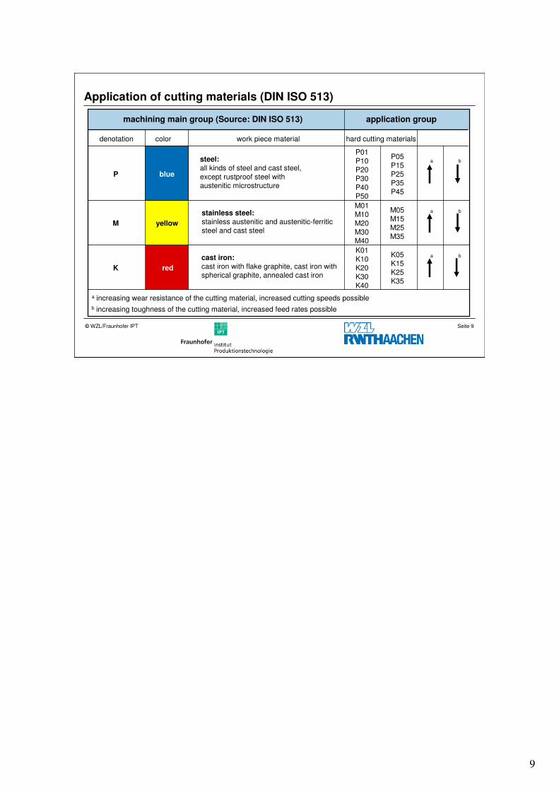
Seite 9© WZL/Fraunhofer IPT
denotation color
P blue
M
K
hard cutting materials
application group
work piece material
yellow
red
P01P10P20P30P40P50
P05P15P25P35P45
M01M10M20M30M40
M05M15M25M35
K01K10K20K30K40
K05K15K25K35
a increasing wear resistance of the cutting material, increased cutting speeds possible
b increasing toughness of the cutting material, increased feed rates possible
a
a
a
b
b
b
machining main group (Source: DIN ISO 513)
steel:all kinds of steel and cast steel,except rustproof steel with austenitic microstructure
stainless steel:stainless austenitic and austenitic-ferriticsteel and cast steel
cast iron:cast iron with flake graphite, cast iron with spherical graphite, annealed cast iron
Application of cutting materials (DIN ISO 513)
10
Seite 10© WZL/Fraunhofer IPT
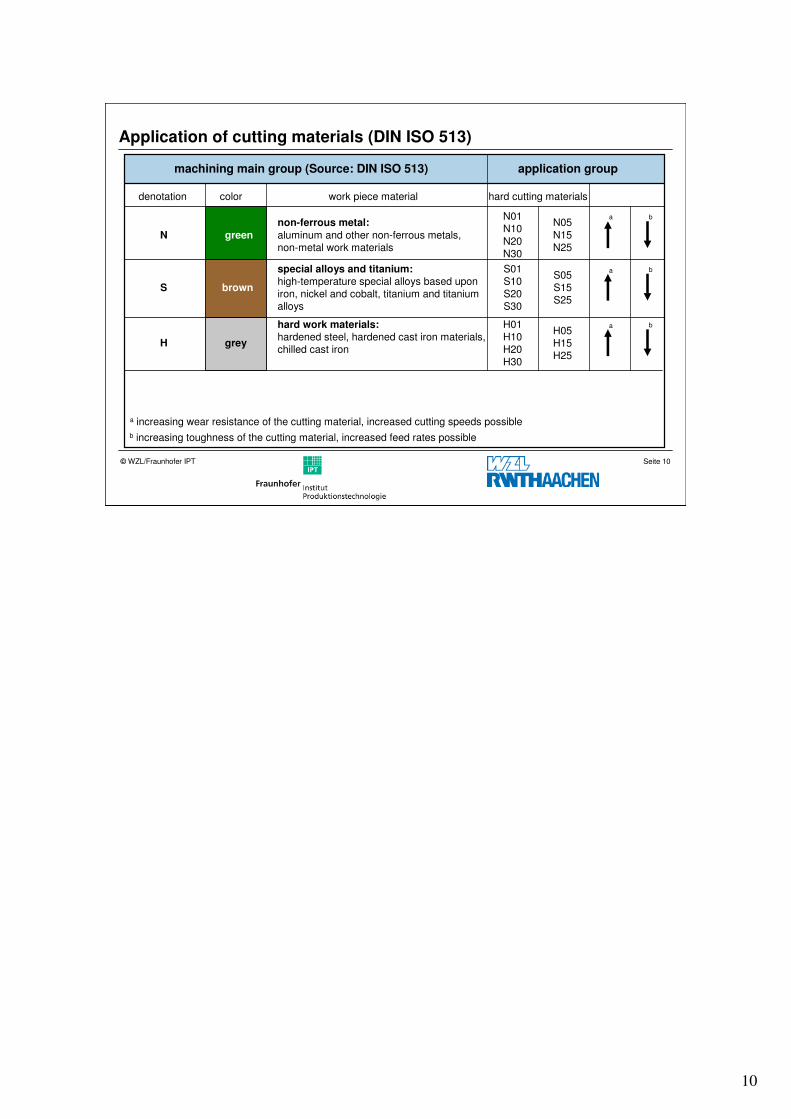
Application of cutting materials (DIN ISO 513)
N
S
H
green
brown
grey
N01N10
N20N30
non-ferrous metal:
aluminum and other non-ferrous metals, non-metal work materials
N05
N15N25
S01S10S20S30
special alloys and titanium:high-temperature special alloys based upon iron, nickel and cobalt, titanium and titanium alloys
S05S15S25
H01H10H20H30
hard work materials:hardened steel, hardened cast iron materials, chilled cast iron
H05H15H25
denotation color hard cutting materialswork piece material
a
a
a
b
b
b
machining main group (Source: DIN ISO 513) application group
a increasing wear resistance of the cutting material, increased cutting speeds possible
b increasing toughness of the cutting material, increased feed rates possible
11
Seite 11© WZL/Fraunhofer IPT
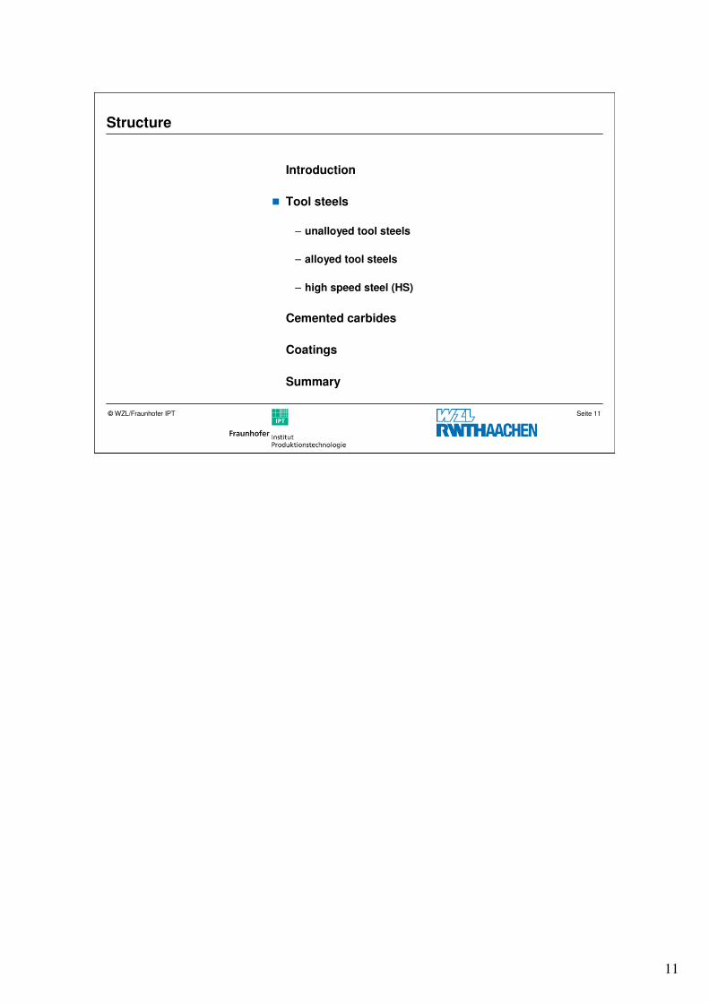
Structure
Introduction
� Tool steels
– unalloyed tool steels
– alloyed tool steels
– high speed steel (HS)
Cemented carbides
Coatings
Summary
12
Seite 12© WZL/Fraunhofer IPT
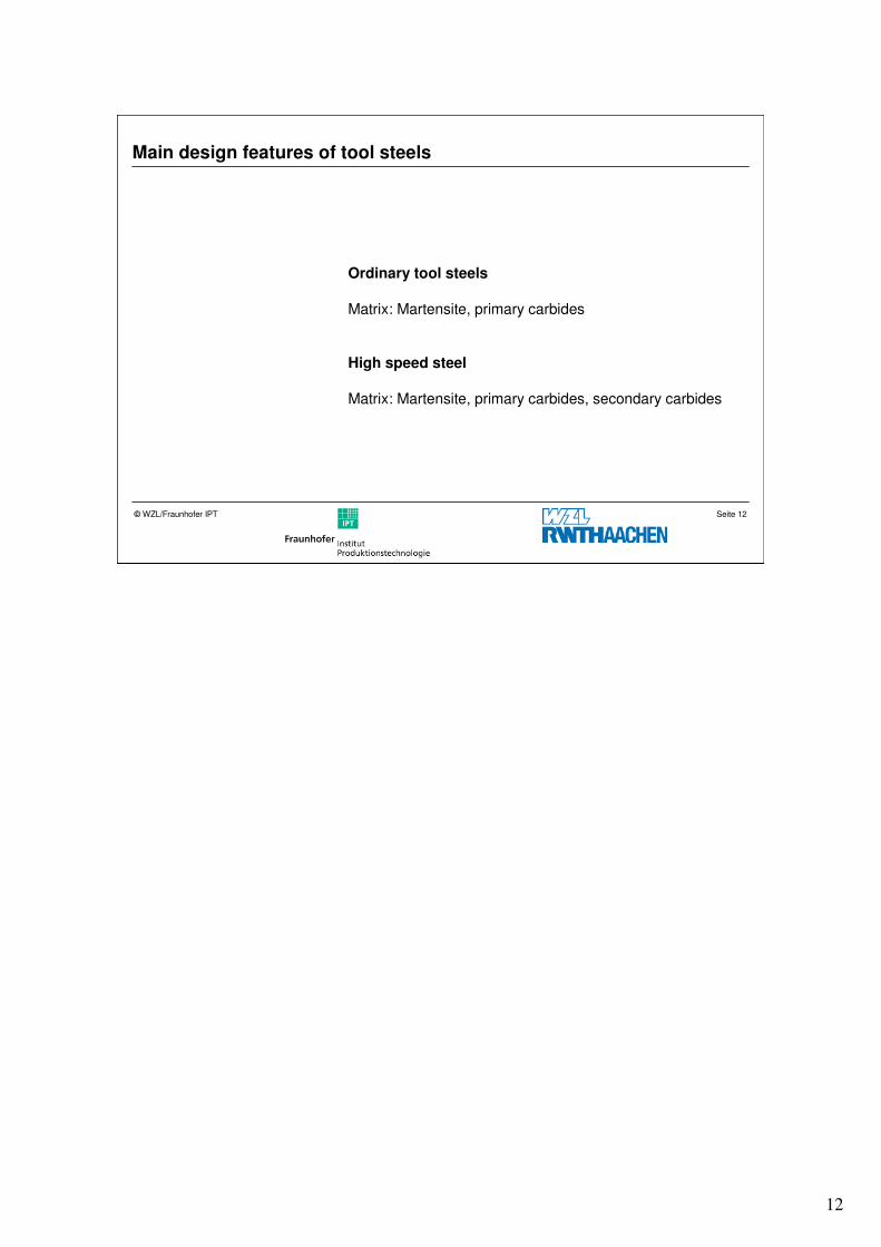
Main design features of tool steels
Ordinary tool steels
Matrix: Martensite, primary carbides
High speed steel
Matrix: Martensite, primary carbides, secondary carbides
13
Seite 13© WZL/Fraunhofer IPT
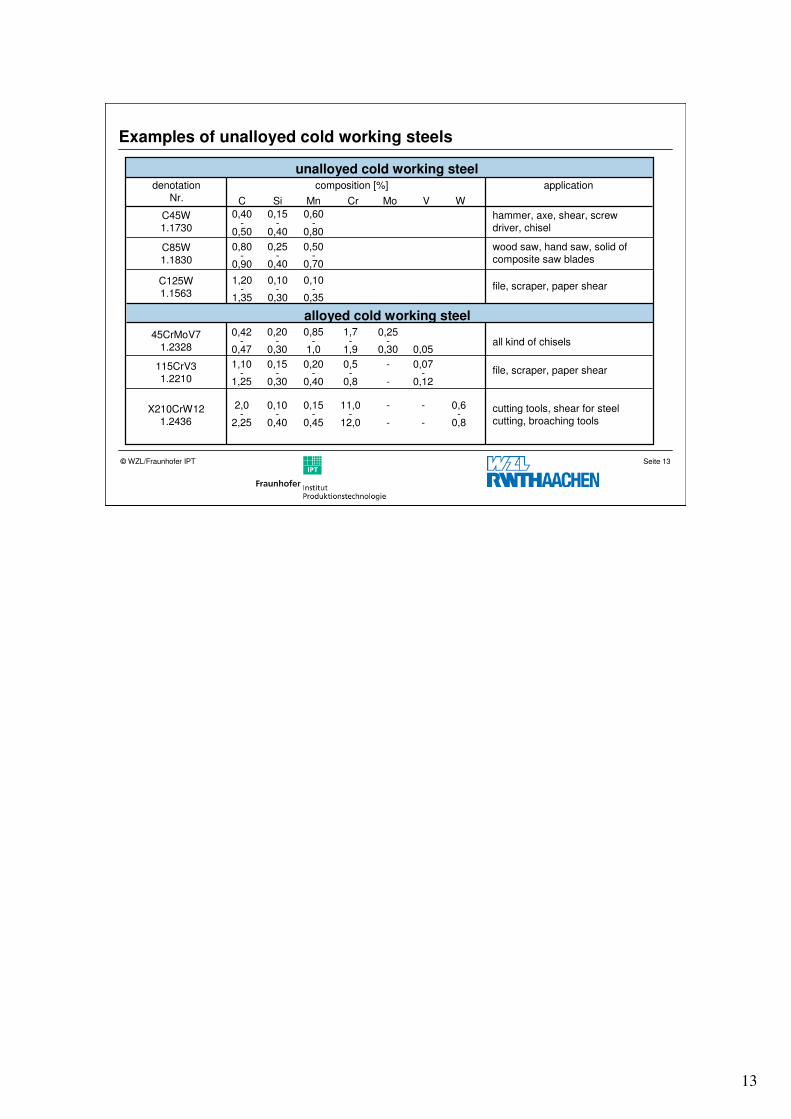
Examples of unalloyed cold working steels
unalloyed cold working steelcomposition [%] application
C Si Mn Cr Mo V W
hammer, axe, shear, screw driver, chisel
wood saw, hand saw, solid of composite saw blades
file, scraper, paper shear
all kind of chisels
file, scraper, paper shear
cutting tools, shear for steel cutting, broaching tools
0,80-
0,90
0,25-
0,40
0,50-
0,70
1,20-
1,35
0,10-
0,30
0,10-
0,35
-0,50
0,40-
0,40
0,15-
0,80
0,60
0,42-
0,47
0,20-
0,30
0,85-
1,0
1,7-
1,9
0,25-
0,30 0,05
1,10-
1,25
0,15-
0,30
0,20-
0,40
0,5-
0,8
-
-
0,07-
0,12
0,15-
0,45
2,0-
2,25
0,10-
0,40
11,0-
12,0
-
-
-
-
0,6-
0,8
C45W1.1730
C85W1.1830
C125W1.1563
45CrMoV71.2328
115CrV31.2210
X210CrW121.2436
alloyed cold working steel
denotationNr.
14
Seite 14© WZL/Fraunhofer IPT
Variations and applications of high speed steels
cutting steel atmedium load maximum load
compo-sition
denotation
W - Mo - V - Co< 850 N/mm2 > 850 N/mm2 roughing finishing
18% WHS18-0-1
HS18-1-2- 5
+
-
-
-
-
+
-
-
12% WHS12-1- 4 - 5
HS10-4- 3 - 10
-
-
-
-
(+)
(+)
+
+
6% W + 5% Mo
HS6-5-2 - + - -
HS6-5- 3 - - (+) +
HS6-5-2- 5 - - + -
2% W + 9% Mo
HS2-9-1
HS2-9-2
HS2-10-1-8
+
-
-
-
+
-
-
-
+
-
-
-
I
II
III
IV
High-speed steels are notated with the letters “HS“ and the indication of the percental
amount of alloying additions in the sequence W-Mo-V-Co, e.g. HS10-4-3-10.
The classification of high-speed steels is raised by their W- and Mo-concentraion into
four alloy- and performance groups.
15
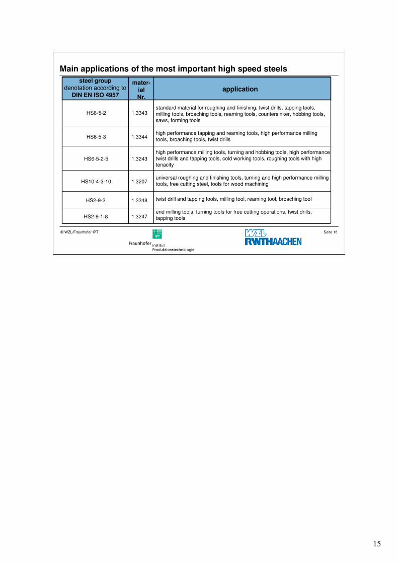
Seite 15© WZL/Fraunhofer IPT
Main applications of the most important high speed steels
steel groupdenotation according to
DIN EN ISO 4957
HS6-5-2
HS6-5-3
HS6-5-2-5
HS10-4-3-10
HS2-9-2
HS2-9-1-8
mater-ialNr.
1.3343
1.3344
1.3243
1.3207
1.3348
1.3247
application
standard material for roughing and finishing, twist drills, tapping tools,
milling tools, broaching tools, reaming tools, countersinker, hobbing tools, saws, forming tools
high performance tapping and reaming tools, high performance millingtools, broaching tools, twist drills
high performance milling tools, turning and hobbing tools, high performancetwist drills and tapping tools, cold working tools, roughing tools with high tenacity
universal roughing and finishing tools, turning and high performance millingtools, free cutting steel, tools for wood machining
twist drill and tapping tools, milling tool, reaming tool, broaching tool
end milling tools, turning tools for free cutting operations, twist drills, tapping tools
16
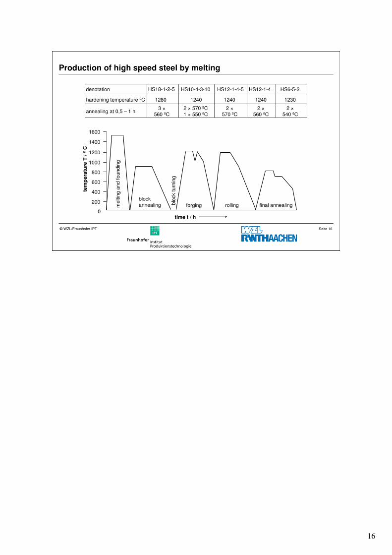
Seite 16© WZL/Fraunhofer IPT
Production of high speed steel by melting
0
200
400
600
800
1000
1200
1400
1600
meltin
g a
nd foundin
g
blo
ck turn
ing
block annealing forging rolling final annealing
tem
pera
ture
T / º
C
time t / h
denotation HS18-1-2-5 HS10-4-3-10 HS12-1-4-5 HS12-1-4 HS6-5-2
hardening temperature ºC 1280 1240 1240 1240 1230
annealing at 0,5 – 1 h3 ×
560 ºC2 × 570 ºC1 × 550 ºC
2 ×570 ºC
2 ×560 ºC
2 ×540 ºC
17
Seite 17© WZL/Fraunhofer IPT
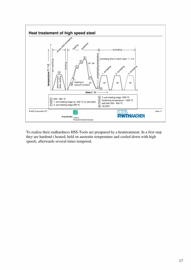
Heat treatement of high speed steel
1. a
nnea
ling
2. a
nnea
ling
oil / air
air air air airheating in vacuum furnace
annealing time in each case: 1 – 2 h
time t / h
slo
w f
urn
ace
dow
n c
oolin
g
tem
pera
ture
T / º
C
com
pensating tem
pera
ture
heat
ing
austen
ize
annealingstre
ss re
lief a
nnea
ling
pre
machin
ing
finis
hin
g
3. a
nnea
ling
A
B
C
D
E
F
G
A 600 - 650 °C
B 1. pre-heating stage ca. 400 °C (in salt bath)
C 2. pre-heating stage 850 ºC
D 3. pre-heating stage 1050 ºC
E hardening temperature ~1200 ºC
F salt bath 500 - 600 ºC
G 50-80ºC
To realize their endhardness HSS-Tools are preapared by a heattreatment. In a first step
they are hardend ( heated, held on austenite temperature and cooled down with high
speed), afterwards several times tempered.
18
Seite 18© WZL/Fraunhofer IPT
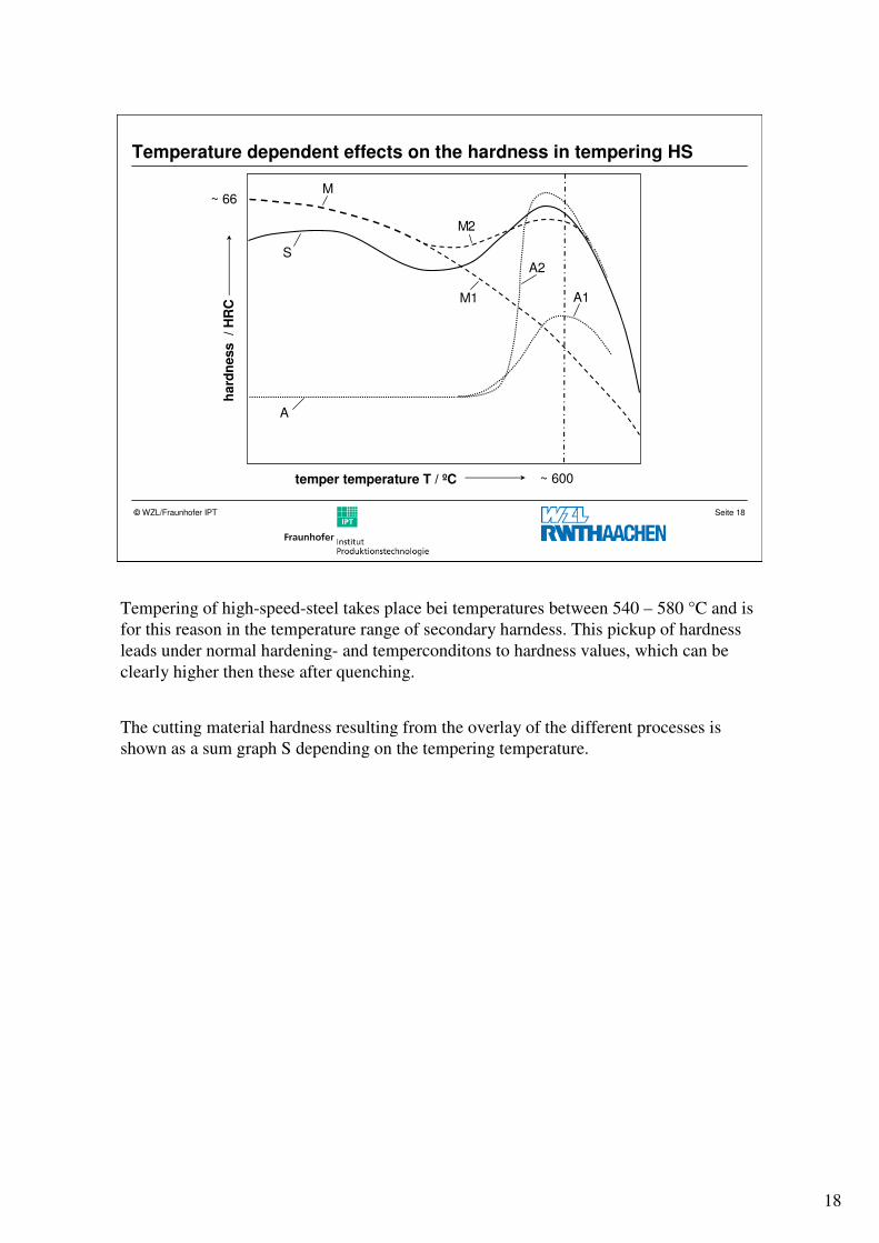
Temperature dependent effects on the hardness in tempering HS
~ 600
A
S
M
A1
A2
M1
M2
~ 66
temper temperature T / ºC
ha
rdn
ess
/
HR
C
Tempering of high-speed-steel takes place bei temperatures between 540 – 580 °C and is
for this reason in the temperature range of secondary harndess. This pickup of hardness
leads under normal hardening- and temperconditons to hardness values, which can be
clearly higher then these after quenching.
The cutting material hardness resulting from the overlay of the different processes is
shown as a sum graph S depending on the tempering temperature.
19
Seite 19© WZL/Fraunhofer IPT
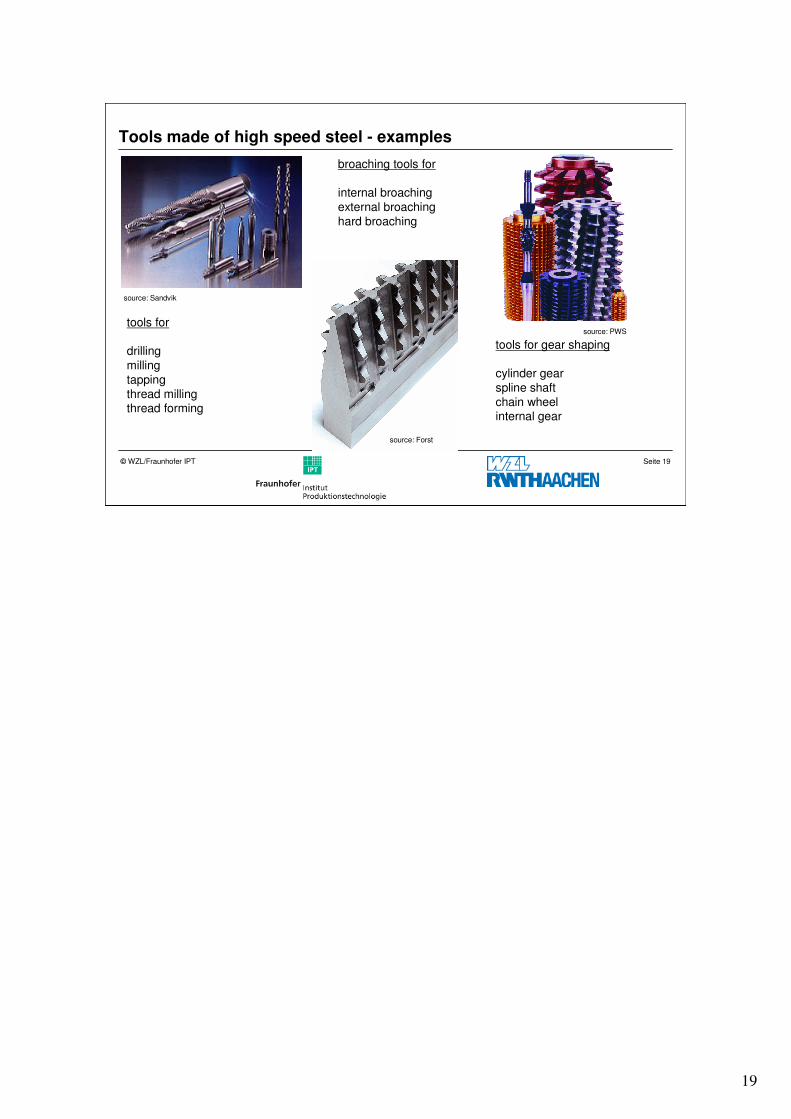
Tools made of high speed steel - examples
source: Forst
source: Sandvik
source: PWS
tools for gear shaping
cylinder gearspline shaft chain wheelinternal gear
broaching tools for
internal broachingexternal broachinghard broaching
tools for
drillingmillingtapping thread millingthread forming
20
Seite 20© WZL/Fraunhofer IPT
Structure
Introduction
Tool steel
� Cemented carbide
– WC-Co-based cemented carbide (HW)
– TiN/TiC-based cemented carbide „cermet“ (HT)
– fine grain cemented carbide
Coatings
Summary
21
Seite 21© WZL/Fraunhofer IPT
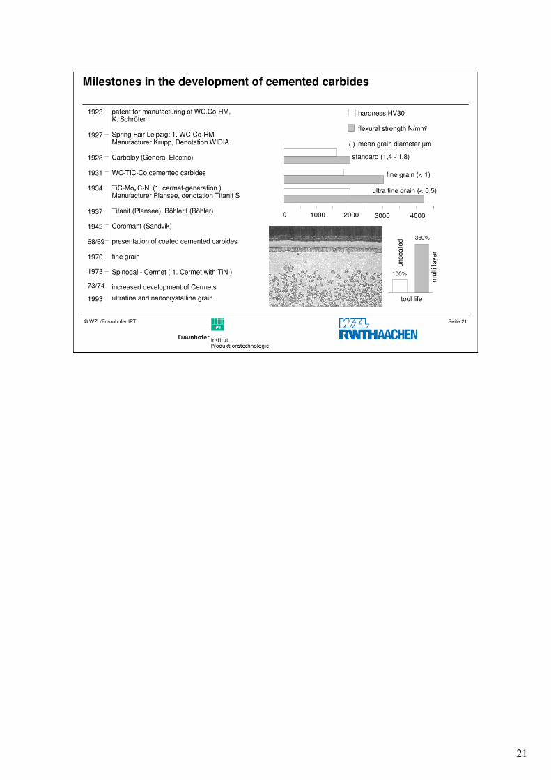
Milestones in the development of cemented carbides
patent for manufacturing of WC.Co-HM,K. Schröter
Spring Fair Leipzig: 1. WC-Co-HMManufacturer Krupp, Denotation WIDIA
Carboloy (General Electric)
WC-TIC-Co cemented carbides
TiC-Mo2 C-Ni (1. cermet-generation )Manufacturer Plansee, denotation Titanit S
Titanit (Plansee), Böhlerit (Böhler)
Coromant (Sandvik)
presentation of coated cemented carbides
fine grain
Spinodal - Cermet ( 1. Cermet with TiN )
increased development of Cermets
ultrafine and nanocrystalline grain
hardness HV30
flexural strength N/mm2
mean grain diameter µm
standard (1,4 - 1,8)
fine grain (< 1)
ultra fine grain (< 0,5)
un
co
ate
d
mu
lti la
yer
0 1000 2000 3000 4000
tool life
1923
100%
360%
1927
1928
1931
1934
1937
1942
68/69
1970
1973
73/74
1993
( )
22
Seite 22© WZL/Fraunhofer IPT
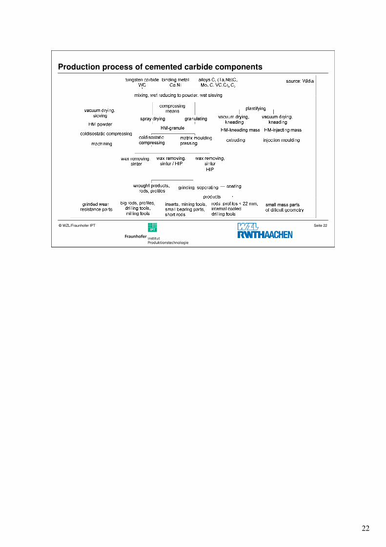
Production process of cemented carbide components
23
Seite 23© WZL/Fraunhofer IPT
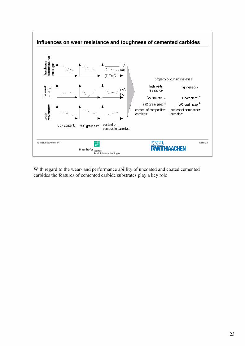
Influences on wear resistance and toughness of cemented carbides
With regard to the wear- and performance abillity of uncoated and coated cemented
carbides the features of cemented carbide substrates play a key role
24
Seite 24© WZL/Fraunhofer IPT
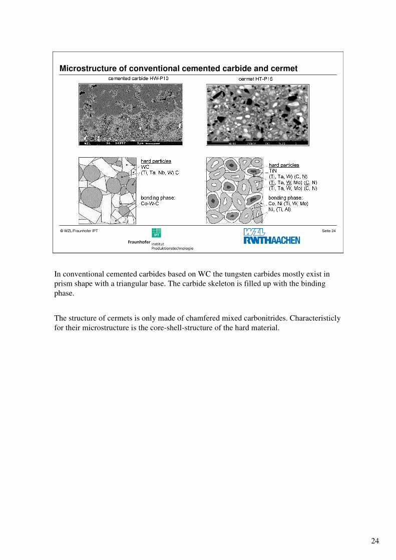
Microstructure of conventional cemented carbide and cermet
In conventional cemented carbides based on WC the tungsten carbides mostly exist in
prism shape with a triangular base. The carbide skeleton is filled up with the binding
phase.
The structure of cermets is only made of chamfered mixed carbonitrides. Characteristicly
for their microstructure is the core-shell-structure of the hard material.
25
Seite 25© WZL/Fraunhofer IPT
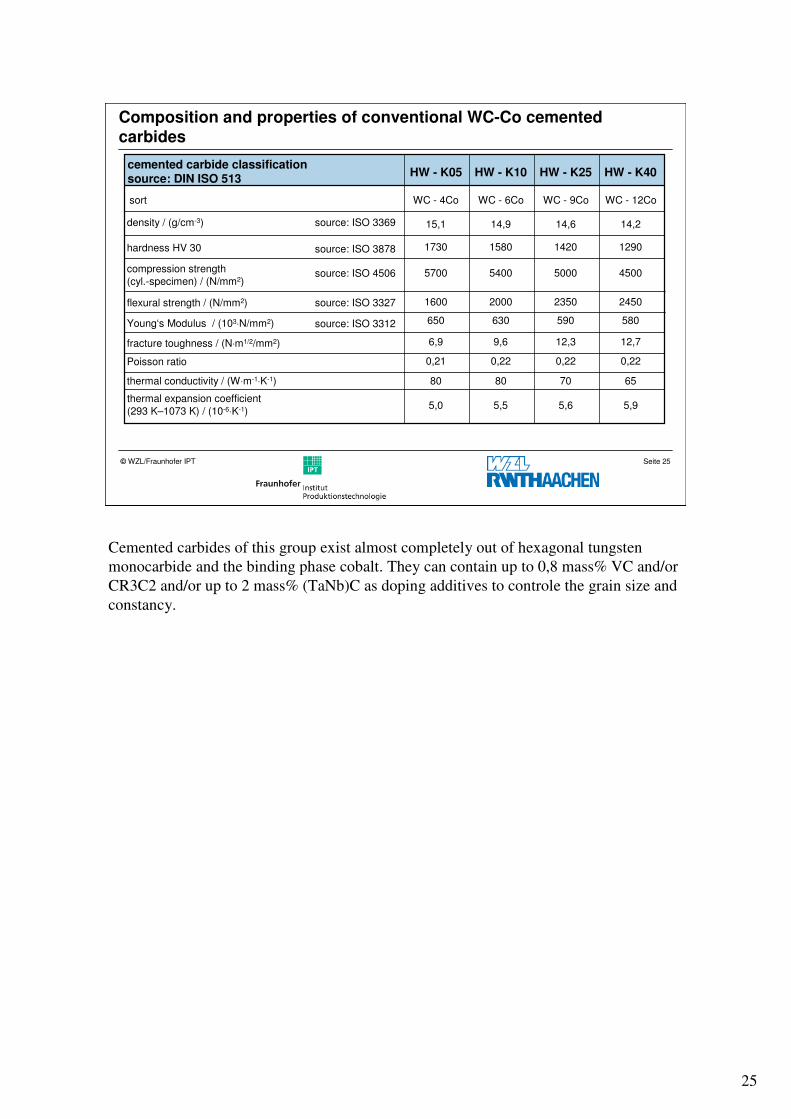
Composition and properties of conventional WC-Co cemented
carbides
cemented carbide classificationsource: DIN ISO 513
HW - K05 HW - K10 HW - K25 HW - K40
sort WC - 4Co WC - 6Co WC - 9Co WC - 12Co
15,1 14,9 14,6 14,2
1730 1580 1420 1290
5700 5400 5000 4500
1600 2000 2350 2450
650 630 590 580
6,9 9,6 12,3 12,7
0,21 0,22 0,22 0,22
80 80 70 65
5,0 5,5 5,6 5,9
source: ISO 3369
source: ISO 3878
source: ISO 4506
source: ISO 3327
source: ISO 3312
density / (g/cm-3)
hardness HV 30
compression strength
(cyl.-specimen) / (N/mm2)
flexural strength / (N/mm2)
Young‘s Modulus / (103⋅N/mm2)
fracture toughness / (N⋅m1/2/mm2)
Poisson ratio
thermal conductivity / (W⋅m-1⋅K-1)
thermal expansion coefficient
(293 K–1073 K) / (10-6⋅K-1)
Cemented carbides of this group exist almost completely out of hexagonal tungsten
monocarbide and the binding phase cobalt. They can contain up to 0,8 mass% VC and/or
CR3C2 and/or up to 2 mass% (TaNb)C as doping additives to controle the grain size and
constancy.
26
Seite 26© WZL/Fraunhofer IPT
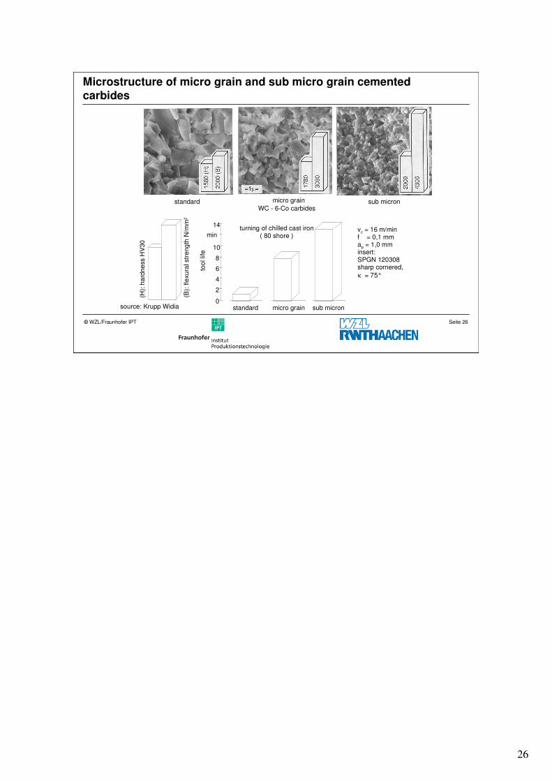
Microstructure of micro grain and sub micro grain cemented
carbides
turning of chilled cast iron( 80 shore )
0
2
4
6
8
10
14
min
too
l lif
e
standard micro grain sub micron
standard micro grain sub micronWC - 6-Co carbides
(H):
ha
rdn
ess H
V30
(B):
fle
xu
ral str
eng
th N
/mm
2
source: Krupp Widia
vc = 16 m/minf = 0,1 mmap = 1,0 mminsert:SPGN 120308sharp cornered,
κ = 75°
27
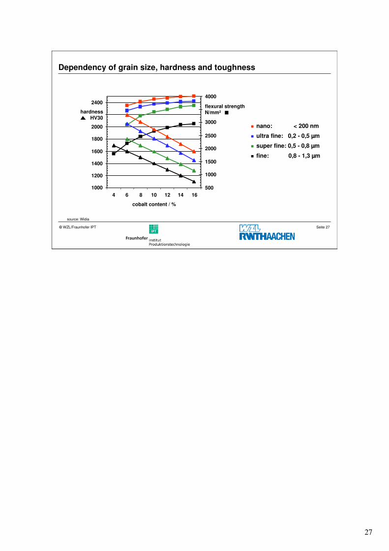
Seite 27© WZL/Fraunhofer IPT
Dependency of grain size, hardness and toughness
source: Widia
� nano: < 200 nm
� fine: 0,8 - 1,3 µm
� super fine: 0,5 - 0,8 µm
� ultra fine: 0,2 - 0,5 µm
1000
1200
1400
1600
1800
2000
2400
hardnessHV30
500
1000
1500
2000
2500
3000
4000
flexural strengthN/mm²
4 6 8 10 12 16
cobalt content / %
14
28
Seite 28© WZL/Fraunhofer IPT
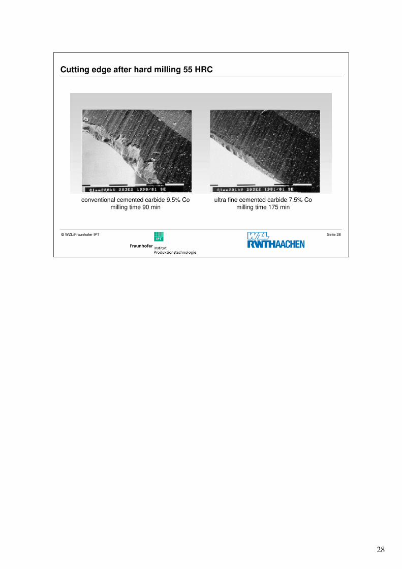
Cutting edge after hard milling 55 HRC
conventional cemented carbide 9.5% Comilling time 90 min
ultra fine cemented carbide 7.5% Comilling time 175 min
29
Seite 29© WZL/Fraunhofer IPT
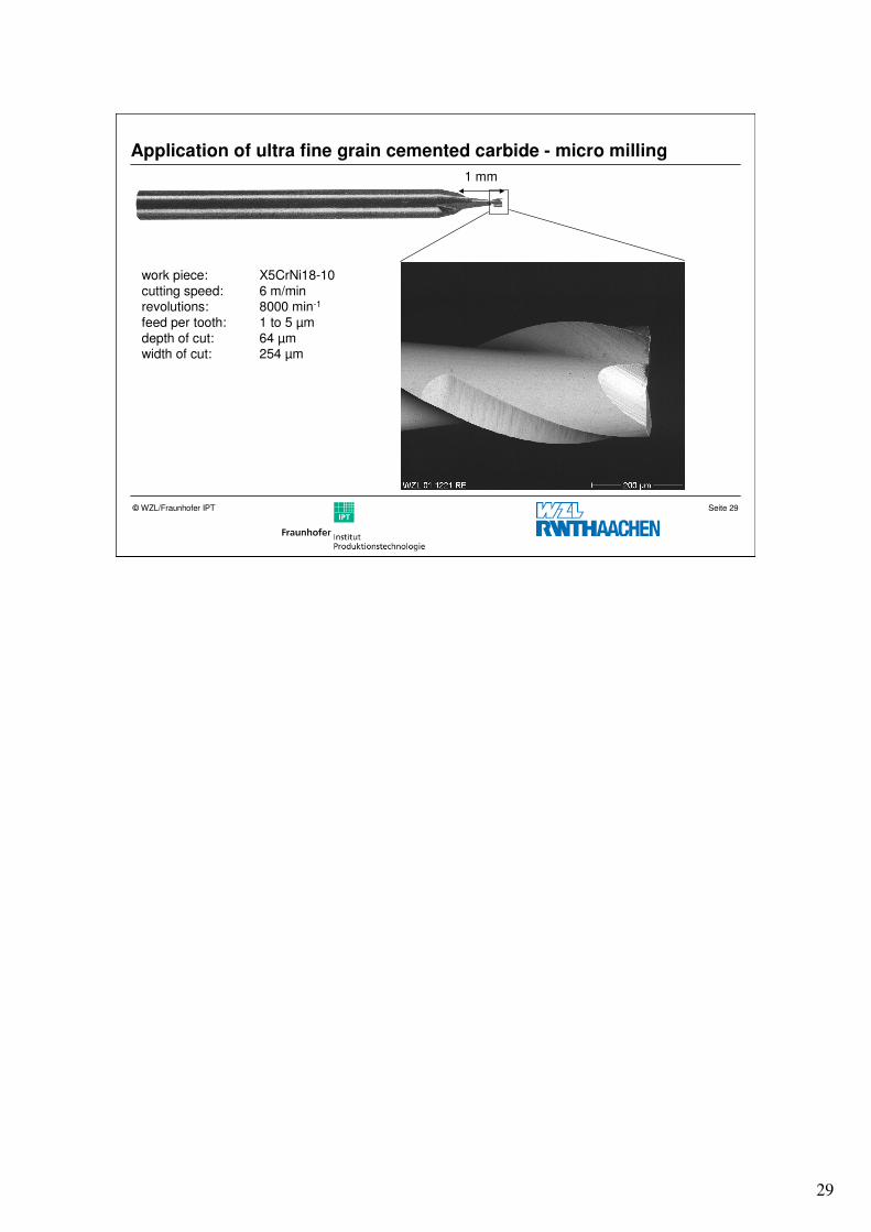
Application of ultra fine grain cemented carbide - micro milling
work piece: X5CrNi18-10cutting speed: 6 m/minrevolutions: 8000 min-1
feed per tooth: 1 to 5 µmdepth of cut: 64 µmwidth of cut: 254 µm
1 mm
30
Seite 30© WZL/Fraunhofer IPT
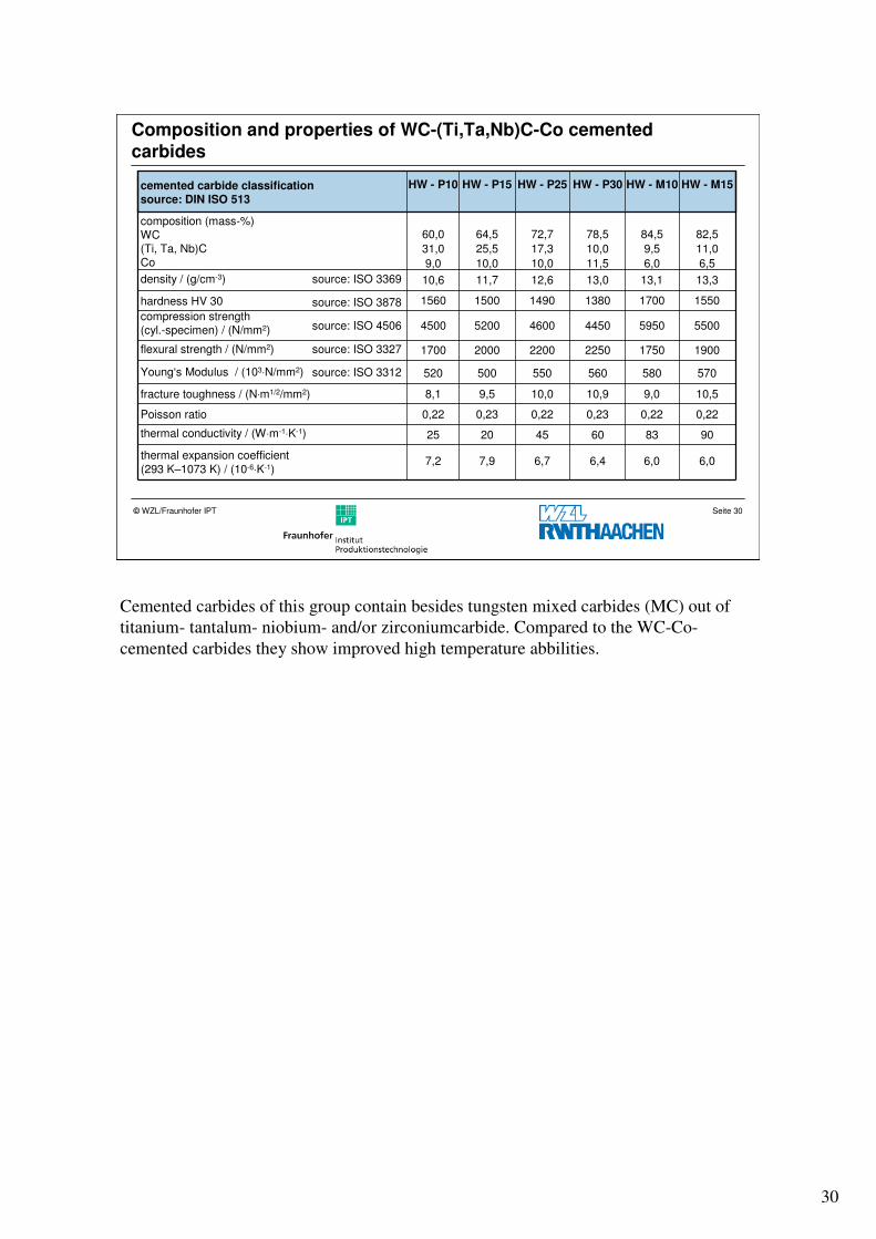
Composition and properties of WC-(Ti,Ta,Nb)C-Co cemented
carbides
cemented carbide classification source: DIN ISO 513
HW - P10 HW - P15 HW - P25 HW - P30 HW - M10 HW - M15
composition (mass-%)WC(Ti, Ta, Nb)CCo
31,0
60,0
9,0
25,5
64,5
10,0
17,3
72,7
10,0
10,0
78,5
11,5
9,5
84,5
6,0
11,0
82,5
6,5
10,6 11,7 12,6 13,0 13,1 13,3
1560 1500 1490 1380 1700 1550
4500 5200 4600 4450 5950 5500
1700 2000 2200 2250 1750 1900
520 500 550 560 580 570
8,1 9,5 10,0 10,9 9,0 10,5
0,22 0,23 0,22 0,23 0,22 0,22
25 20 45 60 83 90
7,2 7,9 6,7 6,4 6,0 6,0
source: ISO 3369
source: ISO 3878
source: ISO 4506
source: ISO 3327
source: ISO 3312
density / (g/cm-3)
hardness HV 30
compression strength(cyl.-specimen) / (N/mm2)
flexural strength / (N/mm2)
Young‘s Modulus / (103⋅N/mm2)
fracture toughness / (N⋅m1/2/mm2)
Poisson ratio
thermal conductivity / (W⋅m-1⋅K-1)
thermal expansion coefficient
(293 K–1073 K) / (10-6⋅K-1)
Cemented carbides of this group contain besides tungsten mixed carbides (MC) out of
titanium- tantalum- niobium- and/or zirconiumcarbide. Compared to the WC-Co-
cemented carbides they show improved high temperature abbilities.
31
Seite 31© WZL/Fraunhofer IPT
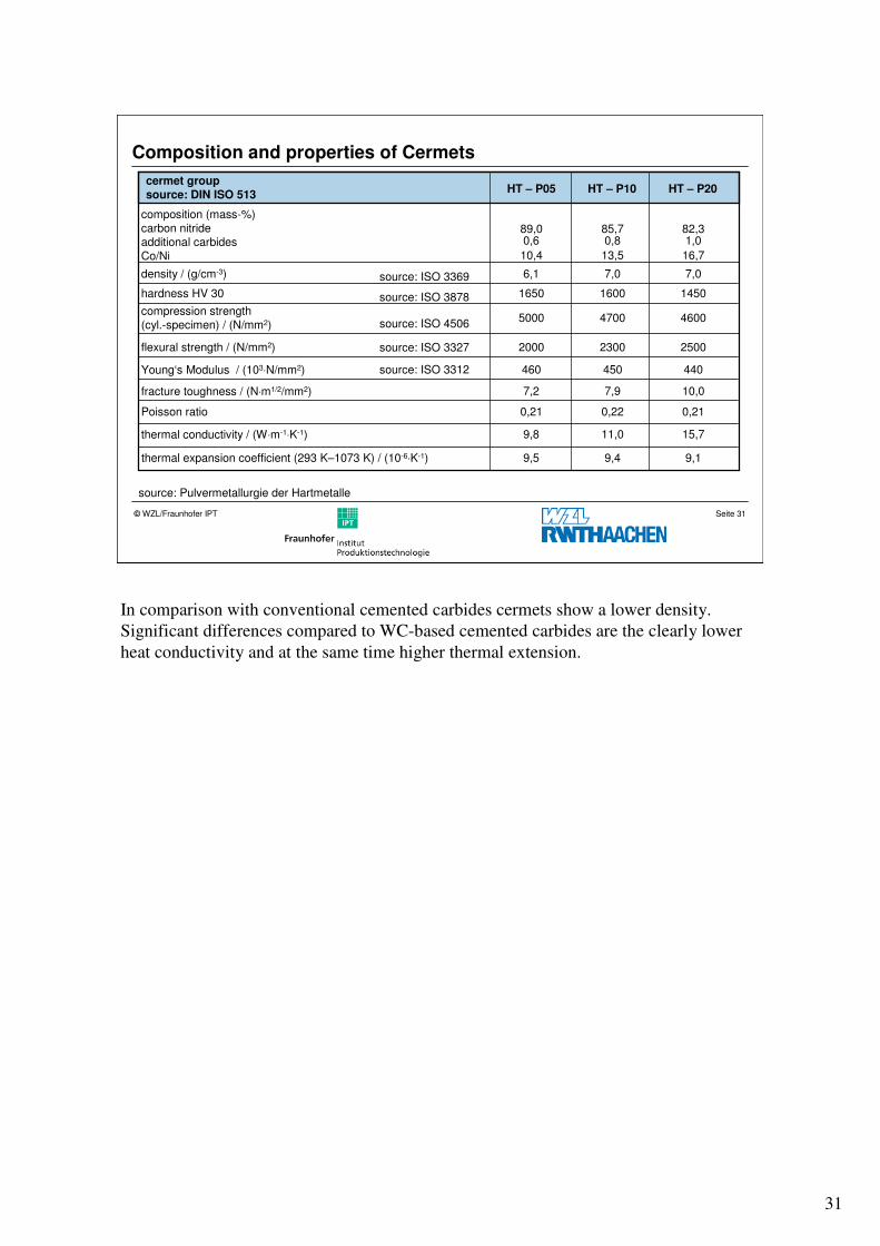
source: Pulvermetallurgie der Hartmetalle
cermet group source: DIN ISO 513
HT – P05 HT – P10 HT – P20
composition (mass-%)carbon nitrideadditional carbidesCo/Ni
89,00,6
10,4
85,70,8
13,5
82,31,0
16,7
source: ISO 3369 6,1 7,0 7,0
source: ISO 3878 1650 1600 1450
source: ISO 45065000 4700 4600
source: ISO 3327 2000 2300 2500
source: ISO 3312 460 450 440
7,2 7,9 10,0
0,21 0,22 0,21
9,8 11,0 15,7
9,5 9,4 9,1
density / (g/cm-3)
hardness HV 30
compression strength(cyl.-specimen) / (N/mm2)
flexural strength / (N/mm2)
Young‘s Modulus / (103⋅N/mm2)
fracture toughness / (N⋅m1/2/mm2)
Poisson ratio
thermal conductivity / (W⋅m-1⋅K-1)
thermal expansion coefficient (293 K–1073 K) / (10-6⋅K-1)
Composition and properties of Cermets
In comparison with conventional cemented carbides cermets show a lower density.
Significant differences compared to WC-based cemented carbides are the clearly lower
heat conductivity and at the same time higher thermal extension.
32
Seite 32© WZL/Fraunhofer IPT
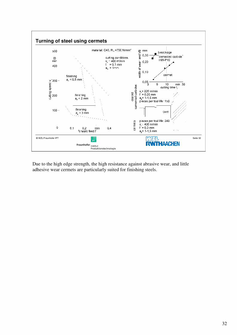
Turning of steel using cermets
Due to the high edge strength, the high resistance against abrasive wear, and little
adhesive wear cermets are particularly suited for finishing steels.
33
Seite 33© WZL/Fraunhofer IPT
Milling with Cermets
end mill,
carbide K25
P
end mill,
cutting speed vc
34
Seite 34© WZL/Fraunhofer IPT
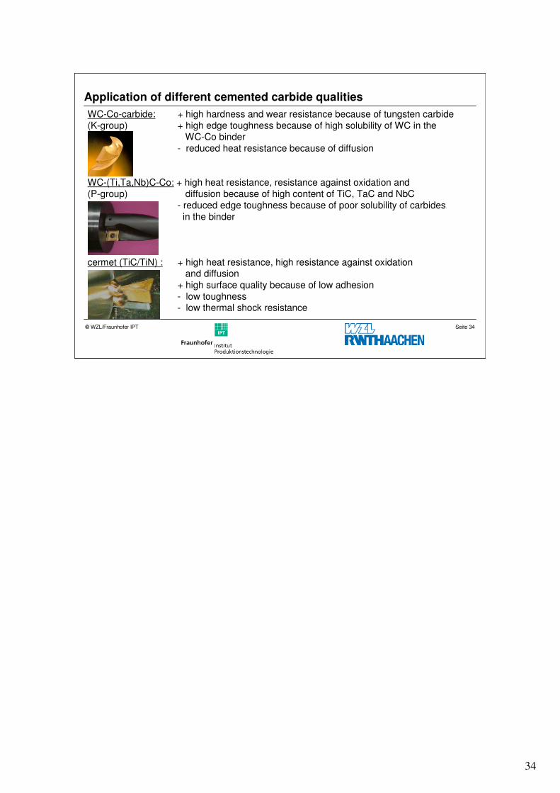
Application of different cemented carbide qualities
WC-Co-carbide: + high hardness and wear resistance because of tungsten carbide(K-group) + high edge toughness because of high solubility of WC in the
WC-Co binder- reduced heat resistance because of diffusion
WC-(Ti,Ta,Nb)C-Co: + high heat resistance, resistance against oxidation and (P-group) diffusion because of high content of TiC, TaC and NbC
- reduced edge toughness because of poor solubility of carbidesin the binder
cermet (TiC/TiN) : + high heat resistance, high resistance against oxidation and diffusion
+ high surface quality because of low adhesion - low toughness- low thermal shock resistance
35
Seite 35© WZL/Fraunhofer IPT
Structure
Introduction
Tool steel
Cemented carbide
� Coatings
– Chemical vapour deposition (CVD)
– Physical vapour deposition (PVD)
Summary
36
Seite 36© WZL/Fraunhofer IPT
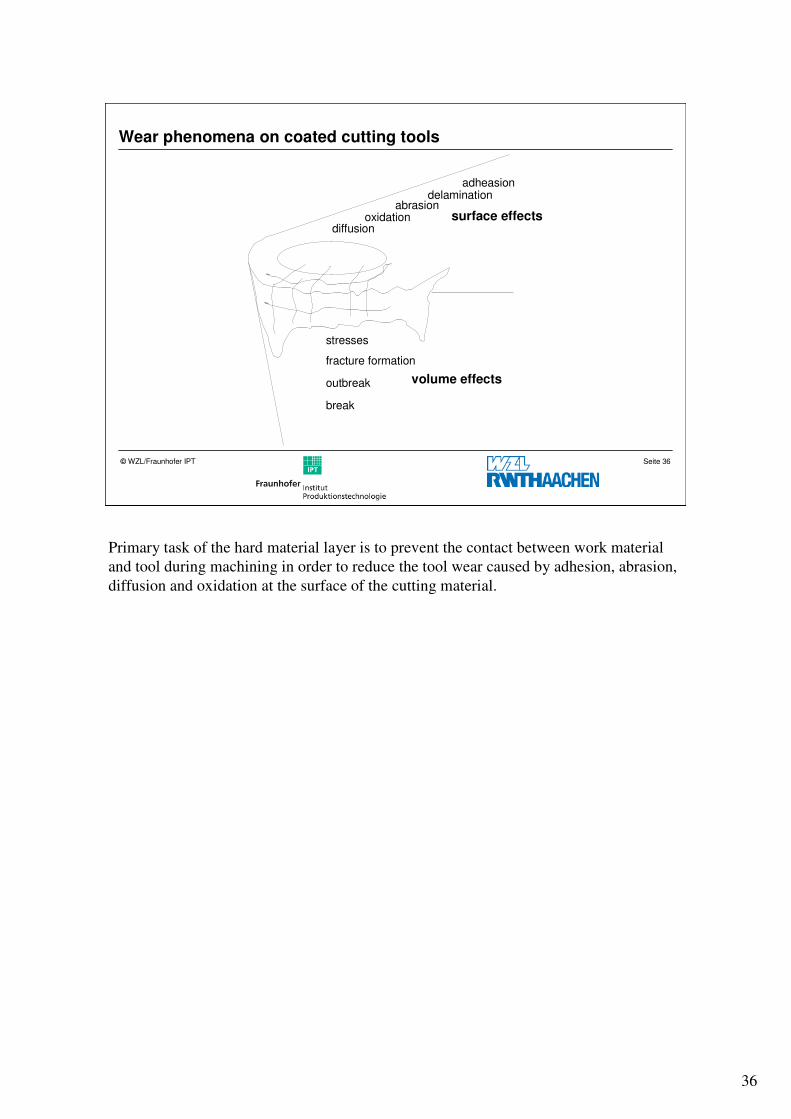
Wear phenomena on coated cutting tools
diffusionoxidation
abrasiondelamination
adheasion
surface effects
volume effects
stresses
fracture formation
outbreak
break
Primary task of the hard material layer is to prevent the contact between work material
and tool during machining in order to reduce the tool wear caused by adhesion, abrasion,
diffusion and oxidation at the surface of the cutting material.
37
Seite 37© WZL/Fraunhofer IPT
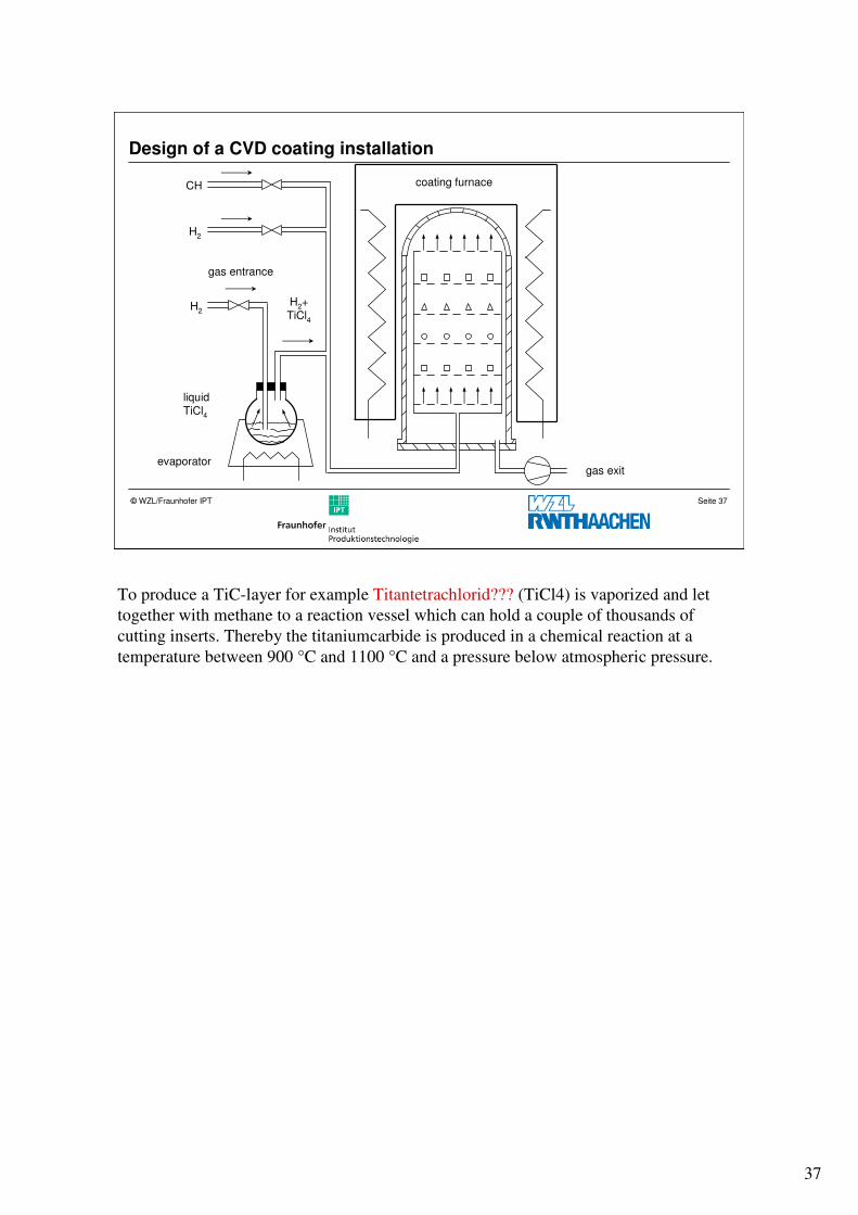
Design of a CVD coating installation
CH
H2
H2+TiCl4
liquidTiCl4
evaporatorgas exit
coating furnace
gas entrance
H2
To produce a TiC-layer for example Titantetrachlorid??? (TiCl4) is vaporized and let
together with methane to a reaction vessel which can hold a couple of thousands of
cutting inserts. Thereby the titaniumcarbide is produced in a chemical reaction at a
temperature between 900 °C and 1100 °C and a pressure below atmospheric pressure.
38
Seite 38© WZL/Fraunhofer IPT
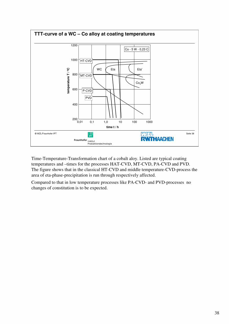
TTT-curve of a WC – Co alloy at coating temperatures
WC Eta Eta'
Co3W
200
400
600
800
1000
1200
0,01 0,1 1,0 10 100 1000
tem
pera
ture
T / º
C
time t / h
Co - 5 W - 0,23 C
HT-CVD
MT-CVD
P-CVD
PVD
Time-Temperature-Transformation chart of a cobalt aloy. Listed are typical coating
temperatures and –times for the processes HAT-CVD, MT-CVD, PA-CVD and PVD.
The figure shows that in the classical HT-CVD and middle temperature-CVD-process the
area of eta-phase-precipitation is run through respectively affected.
Compared to that in low temperature processes like PA-CVD- and PVD-processes no
changes of constitution is to be expected.
39
Seite 39© WZL/Fraunhofer IPT
Coating process and flexural strength
14,5
2,6
F
PA-CVD
PVD
PVD
CVD
ch
an
ge
of
flexu
ralstr
en
gth
/ %
10
10
0
-10
-20
-30
-40
-50
-600 2 4 6 8
700°C
550°C
1000°C
400°C
coating thickness / µm
TiN
TiN/Ti(C,N)
PVD
CVD PVD
PVD
PA-CVD
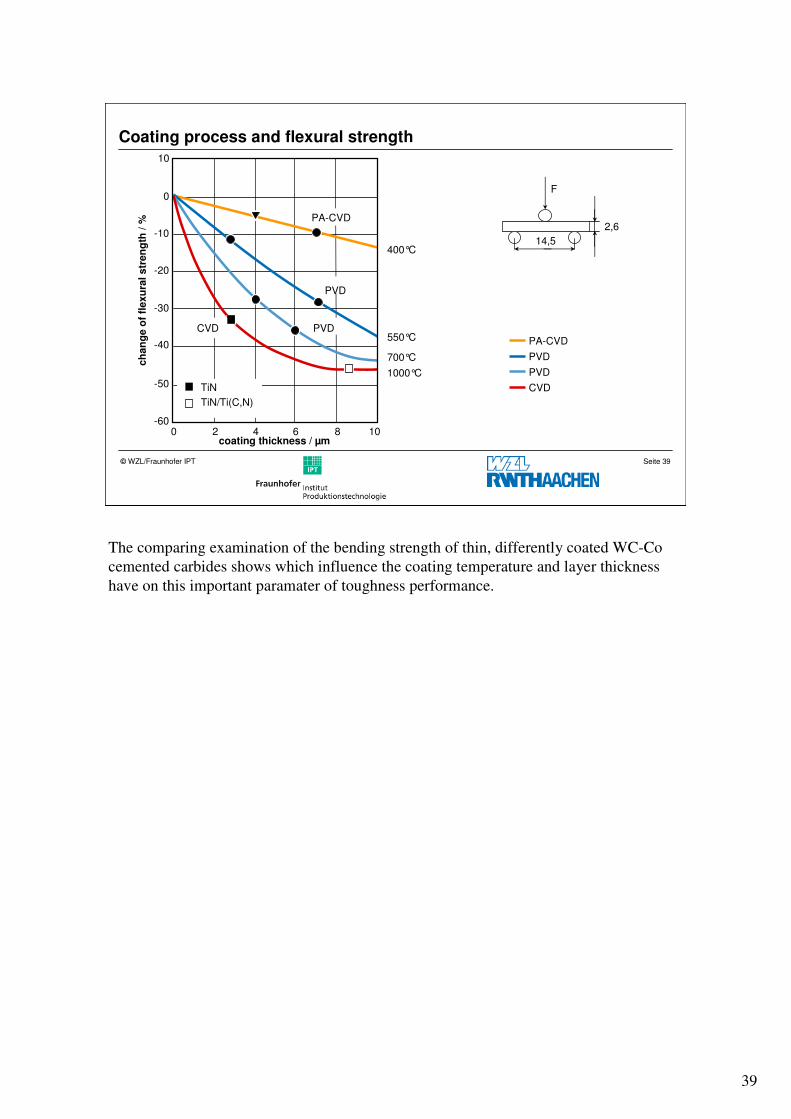
The comparing examination of the bending strength of thin, differently coated WC-Co
cemented carbides shows which influence the coating temperature and layer thickness
have on this important paramater of toughness performance.
40
Seite 40© WZL/Fraunhofer IPT
Coating method and cutting performance
100000
50000
10000
5000
1000
500
10060 80 100 200 400300
imp
ac
tsn
cutting speed vc / (m/min)
work mat.: 42CrMo4+QTRm= 980 N/mm2
substrate: P30/40SPUN 120312f = 0,2 mmap = 2,5 mm
MT-CVD
uncoated
Arc-PVD
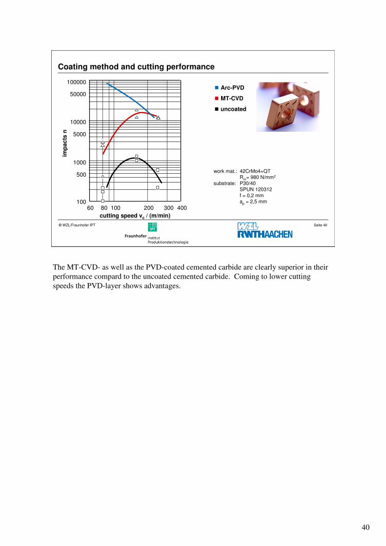
The MT-CVD- as well as the PVD-coated cemented carbide are clearly superior in their
performance compard to the uncoated cemented carbide. Coming to lower cutting
speeds the PVD-layer shows advantages.
41
Seite 41© WZL/Fraunhofer IPT
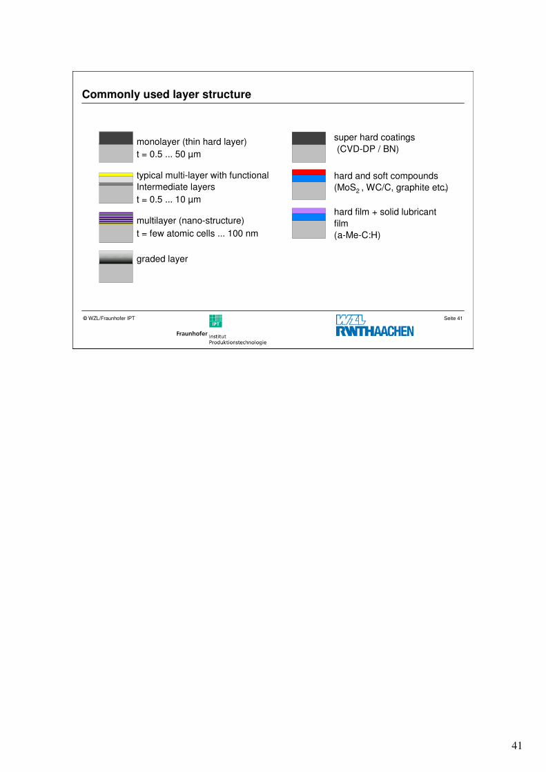
Commonly used layer structure
typical multi-layer with functional
Intermediate layers
multilayer (nano-structure)
graded layer
monolayer (thin hard layer)
t = 0.5 ... 50 µm
t = 0.5 ... 10 µm
t = few atomic cells ... 100 nm
hard and soft compounds
(MoS2 , WC/C, graphite etc..)
hard film + solid lubricant
film
(a-Me-C:H)
super hard coatings
(CVD-DP / BN)
42
Seite 42© WZL/Fraunhofer IPT
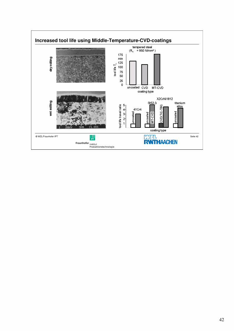
Increased tool life using Middle-Temperature-CVD-coatings
43
Seite 43© WZL/Fraunhofer IPT
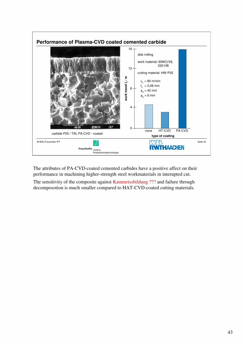
Performance of Plasma-CVD coated cemented carbide
carbide P25 / TiN, PA-CVD - coated
disk milling
work material: 60WCrV8,220 HB
cutting material: HW-P25
vc= 80 m/min
fz = 0,08 mm
ae= 42 mm
ap= 6 mm
type of coating
wo
rktr
avell f
/ m
PA-CVDnone HT-CVD0
4
12
16
8
The attributes of PA-CVD-coated cemented carbides have a positive affect on their
performance in machining higher-strength steel workmaterials in interupted cut.
The sensitivity of the composite against Kammrissbildung ??? and failure through
decomposotion is much smaller compared to HAT-CVD-coated cutting materials.
44
Seite 44© WZL/Fraunhofer IPT
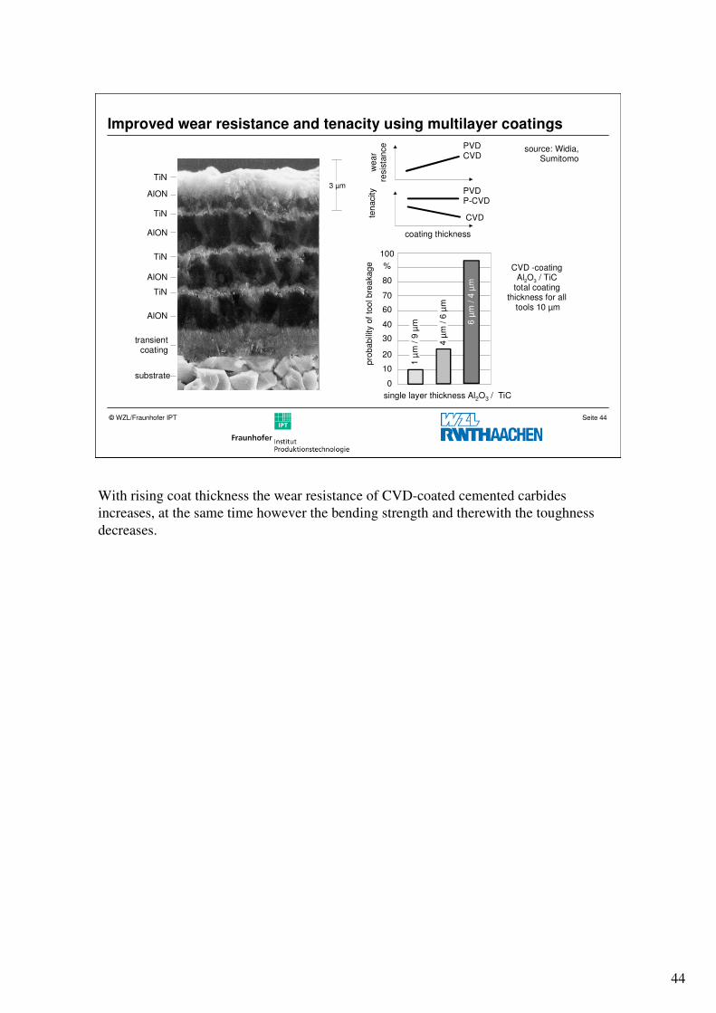
Improved wear resistance and tenacity using multilayer coatings
0
10
20
30
40
60
70
80
%
100
1 µ
m /
9 µ
m
4 µ
m /
6 µ
m
6 µ
m /
4 µ
m
AlON
TiN
AlON
TiN
AlON
TiN
AlON
TiN3 µm
pro
ba
bili
ty o
f to
ol b
rea
ka
ge
single layer thickness Al2O3 / TiC
PVDCVD
PVDP-CVD
CVD
we
ar
resis
tan
ce
ten
acity
coating thickness
transientcoating
substrate
CVD -coatingAl2O3 / TiC
total coating thickness for all
tools 10 µm
source: Widia, Sumitomo
With rising coat thickness the wear resistance of CVD-coated cemented carbides
increases, at the same time however the bending strength and therewith the toughness
decreases.
45
Seite 45© WZL/Fraunhofer IPT
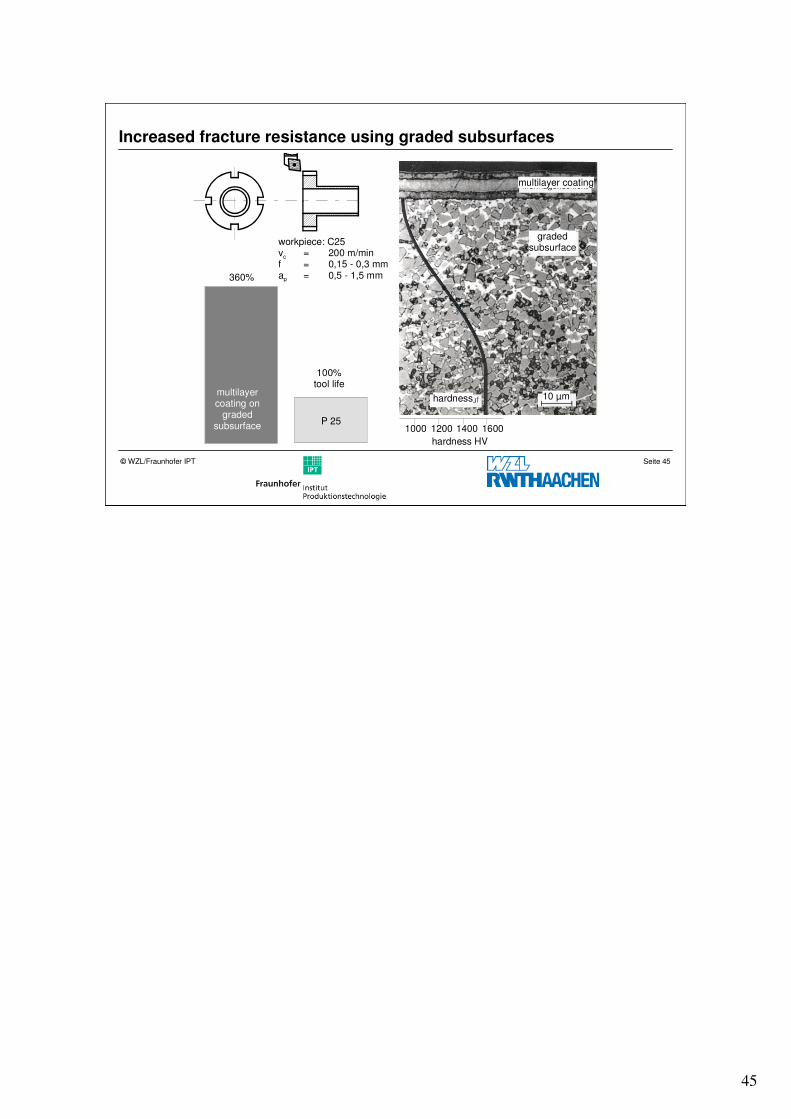
Increased fracture resistance using graded subsurfaces
360%
P 251000 1200 1400 1600
hardness HV
multilayercoating on
gradedsubsurface
100%tool life
workpiece: C25vc = 200 m/minf = 0,15 - 0,3 mmap = 0,5 - 1,5 mm
gradedsubsurface
hardness 10 µm
multilayer coating
46
Seite 46© WZL/Fraunhofer IPT
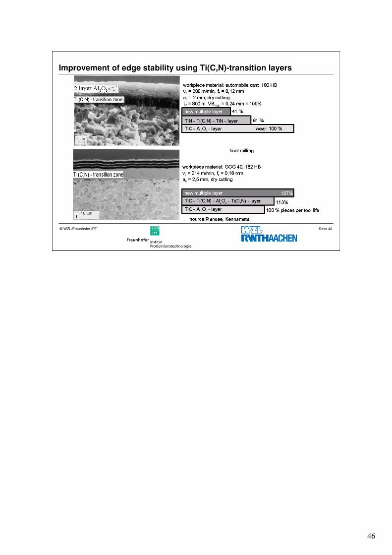
Improvement of edge stability using Ti(C,N)-transition layers
47
Seite 47© WZL/Fraunhofer IPT
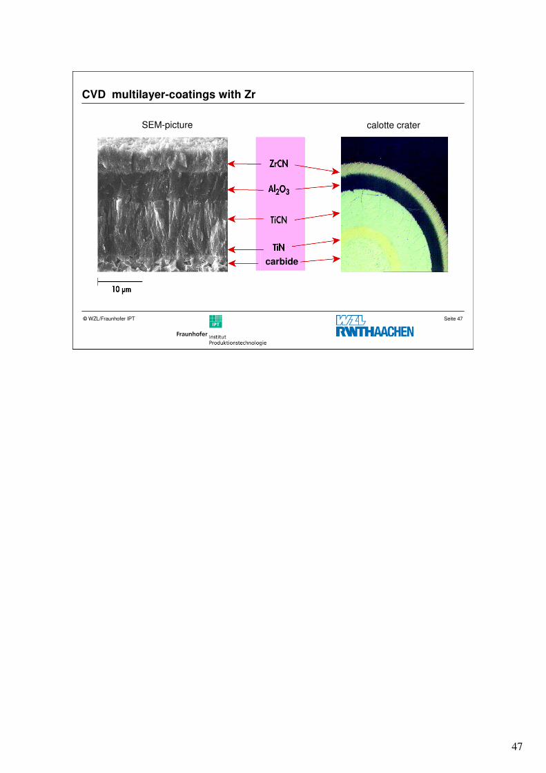
CVD multilayer-coatings with Zr
SEM-picture
carbide
calotte crater
48
Seite 48© WZL/Fraunhofer IPT
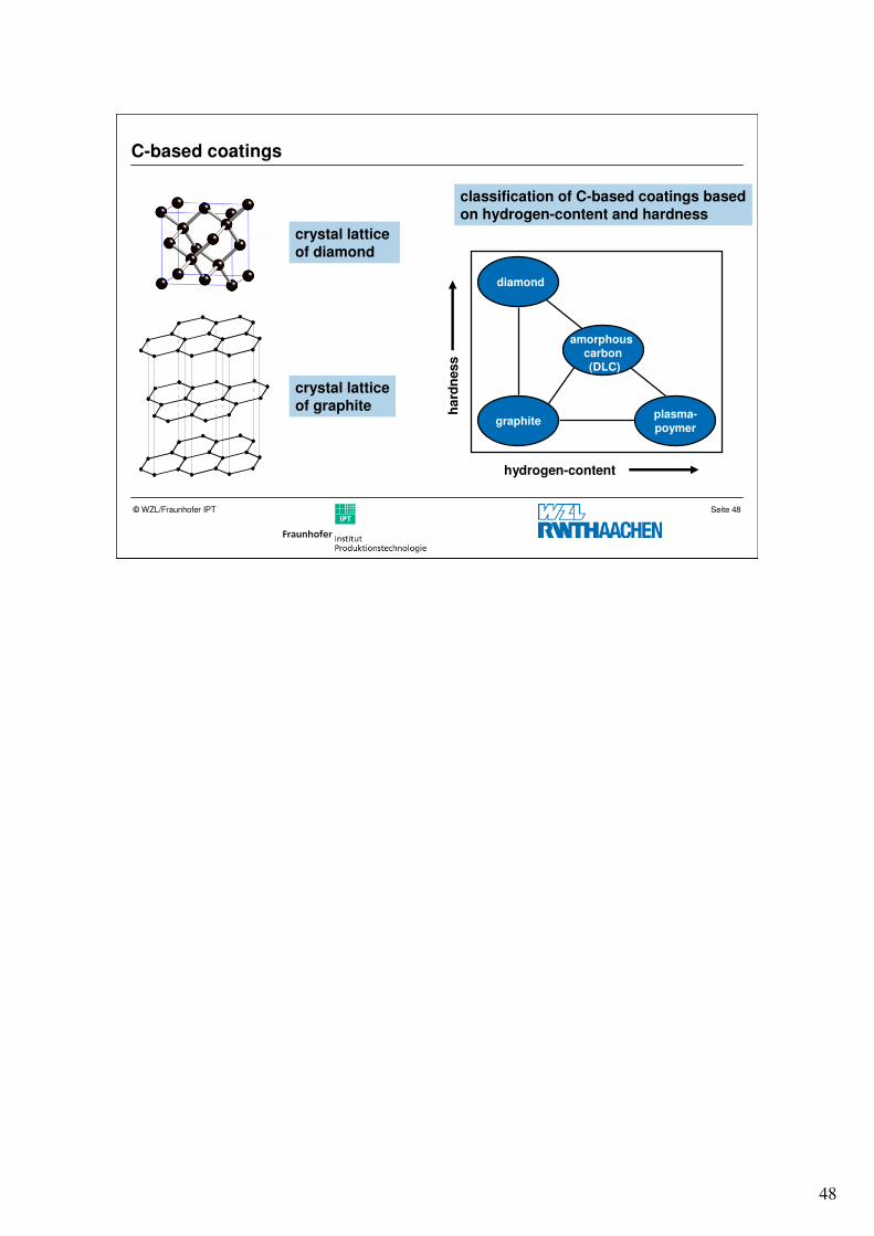
C-based coatings
hydrogen-content
ha
rdn
ess
crystal latticeof graphite
crystal lattice of diamond
classification of C-based coatings basedon hydrogen-content and hardness
diamond
graphiteplasma-
poymer
amorphous carbon(DLC)
49
Seite 49© WZL/Fraunhofer IPT
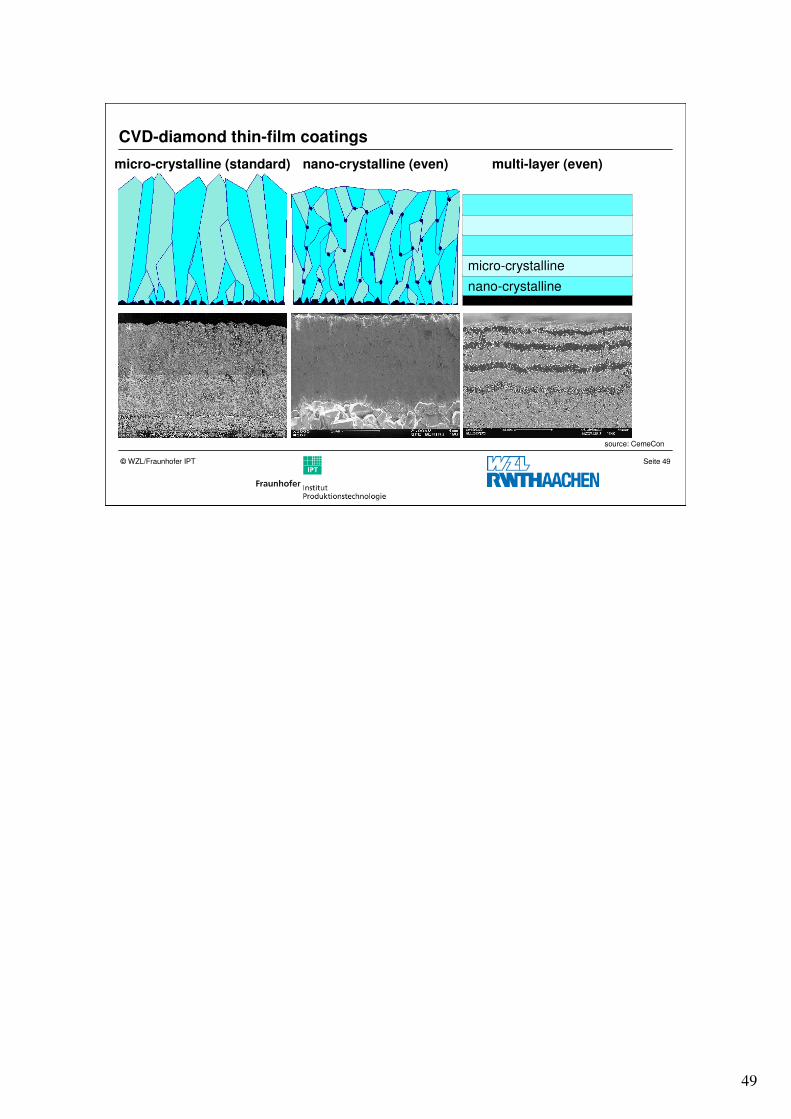
CVD-diamond thin-film coatings
micro-crystalline (standard) nano-crystalline (even) multi-layer (even)
micro-crystalline
nano-crystalline
source: CemeCon
50
Seite 50© WZL/Fraunhofer IPT
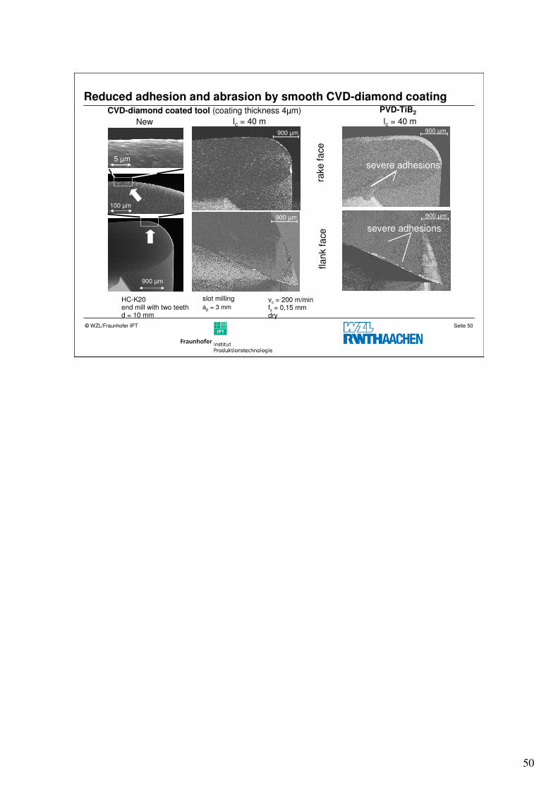
Reduced adhesion and abrasion by smooth CVD-diamond coating
100 µm
5 µm
900 µm
900 µm
rake
fa
ce
900 µm 900 µm
severe adhesions
900 µm
severe adhesions
fla
nk fa
ce
PVD-TiB2CVD-diamond coated tool (coating thickness 4µm)
New lc = 40 m lc = 40 m
vc = 200 m/min fz = 0,15 mm dry
HC-K20 end mill with two teethd = 10 mm
ap = 3 mm
slot milling
51
Seite 51© WZL/Fraunhofer IPT
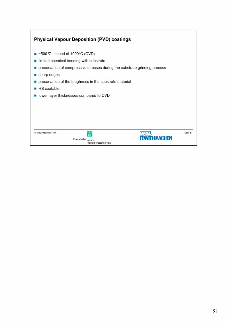
Physical Vapour Deposition (PVD) coatings
� ~500°C instead of 1000°C (CVD)
� limited chemical bonding with substrate
� preservation of compressive stresses during the substrate grinding process
� sharp edges
� preservation of the toughness in the substrate material
� HS coatable
� lower layer thicknesses compared to CVD
52
Seite 52© WZL/Fraunhofer IPT
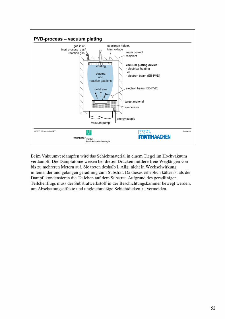
PVD-process – vacuum plating
gas inletinert process gas
reaction gas
vacuum plating device- electrical heatingor
- electron beam (EB-PVD)
vacuum pump
energy supply
evaporator
specimen holder,
bias voltagewater cooled
recipient
electron beam (EB-PVD)
target material
metal ions
plasmaand
reaction gas ions
coating
Beim Vakuumverdampfen wird das Schichtmaterial in einem Tiegel im Hochvakuum
verdampft. Die Dampfatome weisen bei diesen Drücken mittlere freie Weglängen von
bis zu mehreren Metern auf. Sie treten deshalb i. Allg. nicht in Wechselwirkung
miteinander und gelangen geradlinig zum Substrat. Da dieses erheblich kälter ist als der
Dampf, kondensieren die Teilchen auf dem Substrat. Aufgrund des geradlinigen
Teilchenflugs muss der Substratwerkstoff in der Beschichtungskammer bewegt werden,
um Abschattungseffekte und ungleichmäßige Schichtdicken zu vermeiden.
53
Seite 53© WZL/Fraunhofer IPT
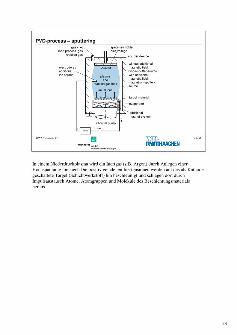
PVD-process – sputtering
vacuum pump
additionalmagnet system
sputter device
- without additionalmagnetic field:diode-sputter-source
- with additionalmagnetic field:magnetron-sputter-source
1…-5 kV
electrode as additionalion source
-+
gas inletinert process gas
reaction gas
metal ions
plasmaand
reaction gas ions
coating
specimen holder,bias voltage
evaporator
target material
In einem Niederdruckplasma wird ein Inertgas (z.B. Argon) durch Anlegen einer
Hochspannung ionisiert. Die positiv geladenen Inertgasionen werden auf das als Kathode
geschaltete Target (Schichtwerkstoff) hin beschleunigt und schlagen dort durch
Impulsaustausch Atome, Atomgruppen und Moleküle des Beschichtungsmaterials
heraus.
54
Seite 54© WZL/Fraunhofer IPT
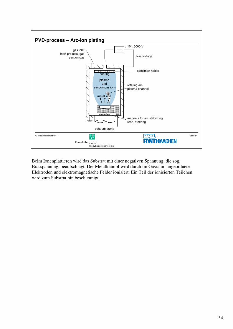
PVD-process – Arc-ion plating
gas inletinert process gas
reaction gas
vacuum pump
magnets for arc stabilizingresp. steering
rotating arcplasma channel
10…5000 V- +
bias voltage
specimen holder
metal ions
plasmaand
reaction gas ions
coating
Beim Ionenplattieren wird das Substrat mit einer negativen Spannung, die sog.
Biasspannung, beaufschlagt. Der Metalldampf wird durch im Gasraum angeordnete
Elektroden und elektromagnetische Felder ionisiert. Ein Teil der ionisierten Teilchen
wird zum Substrat hin beschleunigt.
55
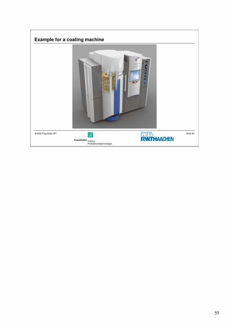
Seite 55© WZL/Fraunhofer IPT
Example for a coating machine
56
Seite 56© WZL/Fraunhofer IPT
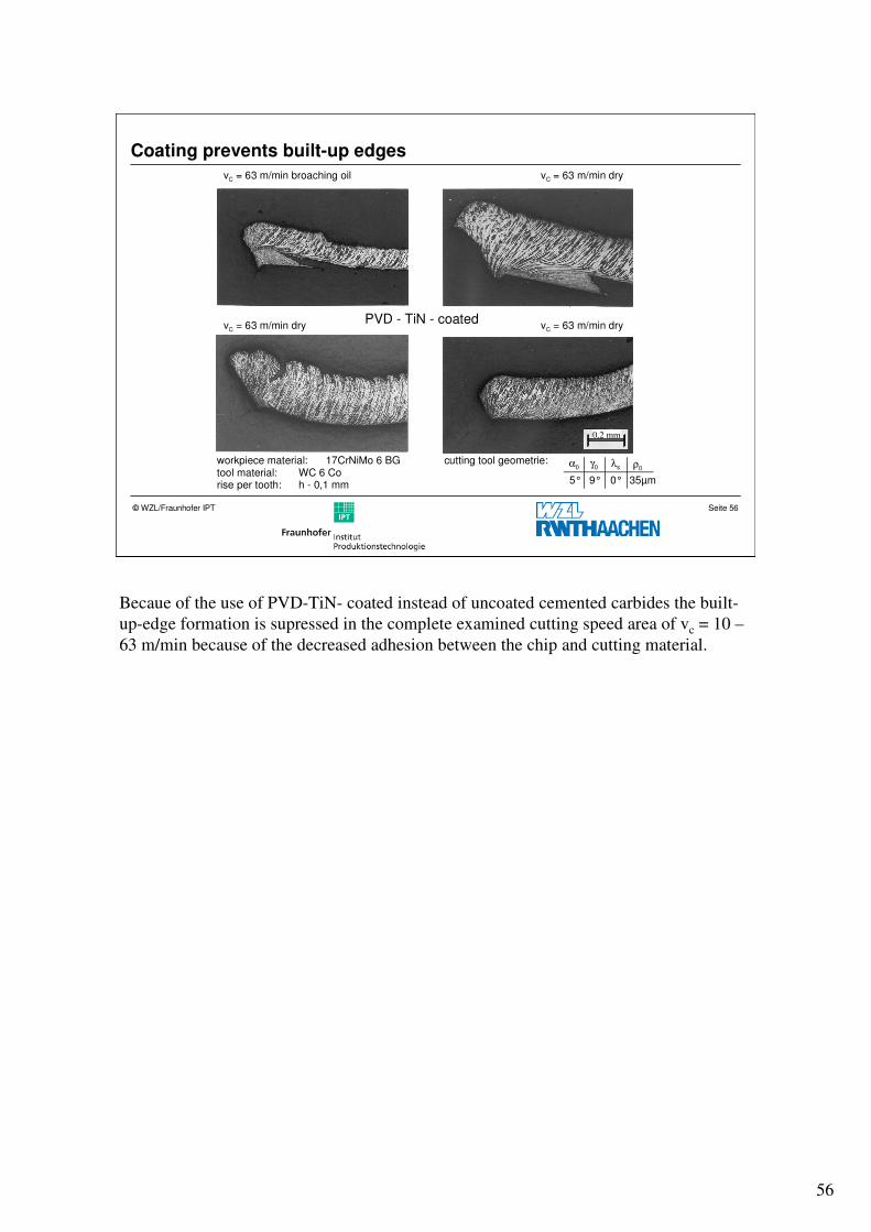
Coating prevents built-up edges
0,2 mm
α0 λs ρ0γ0
5° 9° 0° 35µm
PVD - TiN - coated
vC = 63 m/min broaching oil vC = 63 m/min dry
vC = 63 m/min dry vC = 63 m/min dry
workpiece material: 17CrNiMo 6 BGtool material: WC 6 Corise per tooth: h - 0,1 mm
cutting tool geometrie:
Becaue of the use of PVD-TiN- coated instead of uncoated cemented carbides the built-
up-edge formation is supressed in the complete examined cutting speed area of vc = 10 –
63 m/min because of the decreased adhesion between the chip and cutting material.
57
Seite 57© WZL/Fraunhofer IPT
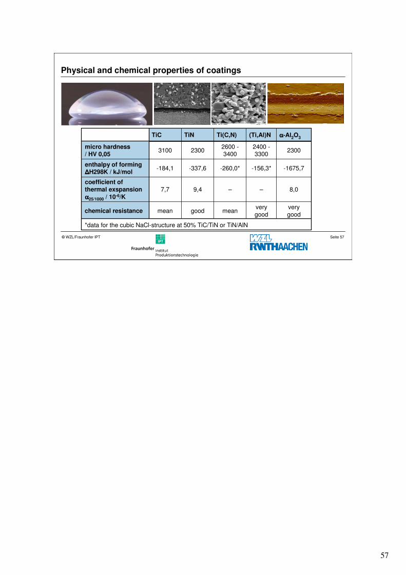
Physical and chemical properties of coatings
*data for the cubic NaCl-structure at 50% TiC/TiN or TiN/AlN
verygood
verygood
meangoodmeanchemical resistance
8,0––9,47,7
coefficient of thermal exspansion
αααα25/1000 / 10-6/K
-1675,7-156,3*-260,0*-337,6-184,1enthalpy of formingΔΔΔΔH298K / kJ/mol
23002400 -3300
2600 -3400
23003100micro hardness/ HV 0,05
αααα-Al2O3(Ti,Al)NTi(C,N)TiNTiC
58
Seite 58© WZL/Fraunhofer IPT
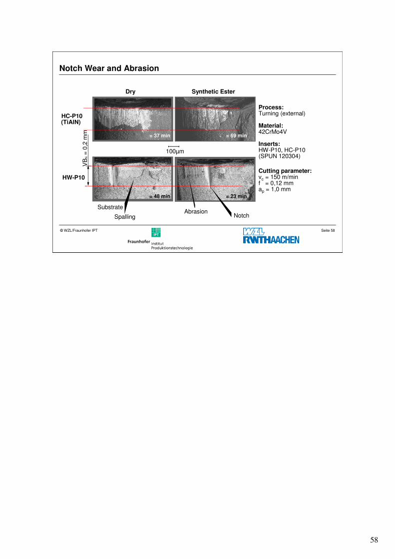
Notch Wear and Abrasion
HW-P10
HC-P10(TiAlN)
Dry Synthetic Ester
Substrate
Spalling
100µm
Notch
= 37 min
VB
N=
0,2
mm
Process:Turning (external)
Material:42CrMo4V
Inserts:HW-P10, HC-P10(SPUN 120304)
Cutting parameter:vc = 150 m/minf = 0,12 mmap = 1,0 mm
Abrasion
= 69 min
= 48 min = 23 min
59
Seite 59© WZL/Fraunhofer IPT
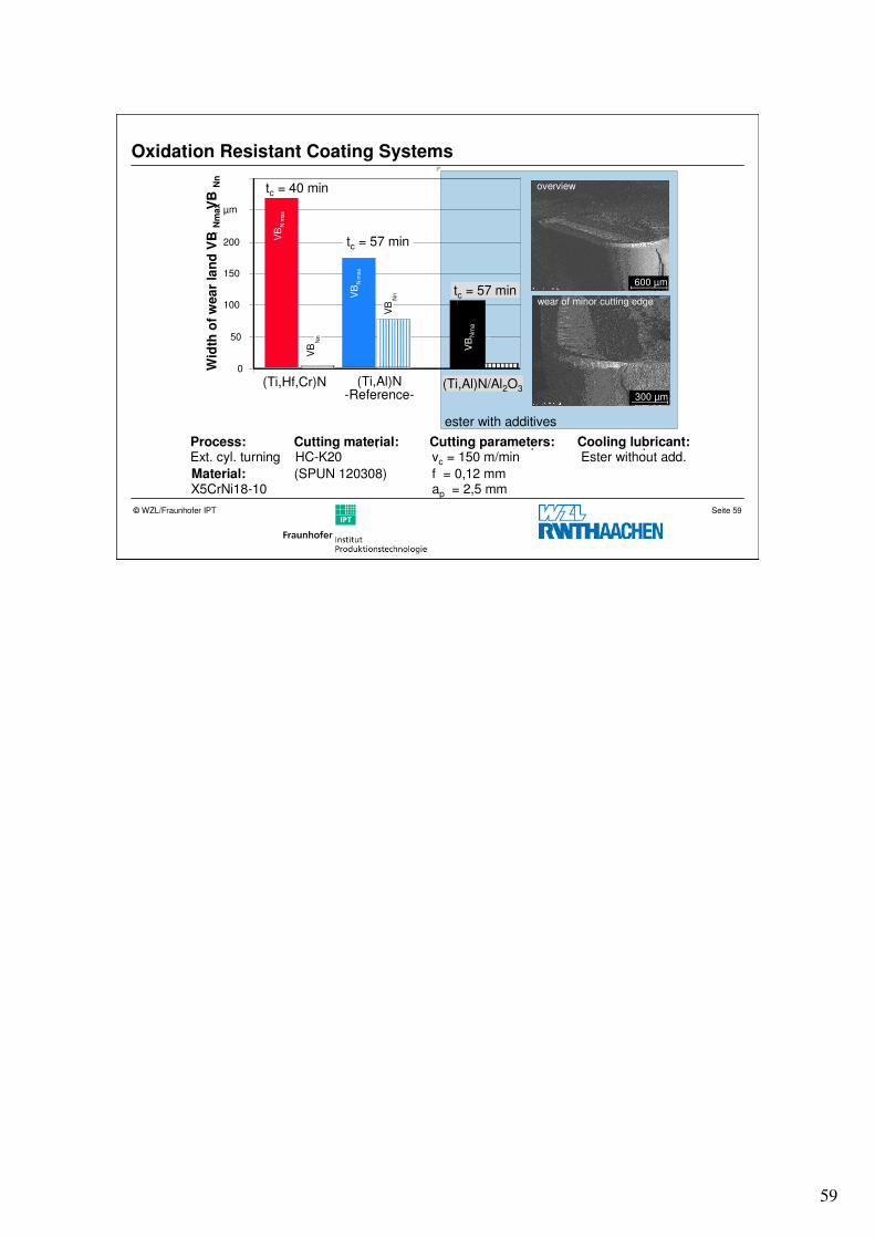
Oxidation Resistant Coating Systems
ester with additives
overview
wear of minor cutting edge
600 µm
300 µm
VB
Nm
a
x
(Ti,Al)N/Al2O3
tc = 57 min
Process:Ext. cyl. turning
Material:X5CrNi18-10
Cutting material::HC-K20
(SPUN 120308)
Cooling lubricant::Ester without add.
Cutting parameters::vc = 150 m/min
f = 0,12 mmap = 2,5 mm
0
50
100
150
200
µmW
idth
of
wea
rla
nd
VB
Nm
ax
,
V
B N
n
(Ti,Hf,Cr)N (Ti,Al)N-Reference-
VB
Nn
tc = 40 min
tc = 57 min VB
Nm
ax
VB
Nn
VB
Nm
ax
60
Seite 60© WZL/Fraunhofer IPT
Structure
Introduction
Tool steel
Cemented carbide
Coatings
� Summary
61
Seite 61© WZL/Fraunhofer IPT
Questions
� Which are the main components in high speed steel (HS), WC-Co-based cemented carbides (HW) and cermets (HT)?
� Why are complex tools such as broaching and gear hobbing mills often made of high speed steel (HS)!
� Why do cermets (HT) have a higher thermal strength than WC-Co-based cemented carbides (HW)?
� A given finishing turning process does not deliver the required surface finish. The surface obtained is too rough. What measures can be taken to increase the surface finish.
� Cemented carbides from the P-group have high content of TiC, TaC and NbC carbides, low content of WC. What is the benefit of this composition, what are the disadvantages?
� What are the advantages of CVD-coatings compared to PVD-coatings?
� A high speed steel has to be coated. What type of process (CVD, PCD) do you consider.
� What wear effects can be influenced by a coating?
� What are main failure effects of coating?
62
Seite 62© WZL/Fraunhofer IPT
Questions
� How does particle size in cemented carbides influence toughness
� What can be done to overcome build up edges
� What are the main conditions to promote adhesive wear
� What can be done to prevent adhesion
� Which material more sensitive to adhesion (compare against tool steel): Aluminum, carbon steel (0,6% C) or grey cast iron (GG 15)
� Show for K - grade carbides the dependence of grit size and cobalt contend on toughness
� Show for K - grade carbides the dependence of grit size and cobalt contend on hardness