Embed Size (px)
Citation preview

PEER-REVIEWED ARTICLE bioresources.com
Teng et al. (2014). “Cutting forces for MDF,” BioResources 9(4), 5845-5857. 5845
Cutting Forces and Chip Morphology in Medium Density Fiberboard Orthogonal Cutting
Yu Teng, Jianwen Ding, Baojin Wang, Xiaolei Guo,* and Pingxiang Cao
The influence of rake angle, cutting speed, and uncut chip thickness on cutting forces and chip morphology in medium density fiberboards orthogonal cutting was investigated. With regard to the normal cutting force and the feed force recorded, there were important variations when machining conditions were modified, or when some tool characteristics were changed. The findings led to the conclusion that there was a close relationship between the cutting conditions and chip formations as well as the cutting forces. Such forces were found to be particularly sensitive to changes in uncut chip thickness, as well as showing dependence on the cutting speed of the tools in orthogonal cutting.
Keywords: Medium Density Fiberboard; Cutting force; Chip morphology; Uncut Chip thickness;
Rake angle; Cutting speed
Contact information: Faculty of Material Science and Engineering, Nanjing Forestry University, Nanjing
210037, China; *Corresponding author: [email protected]
INTRODUCTION
Medium density fiberboard (MDF) is a widely used engineering wood product for
both interior and exterior construction applications. For many applications, the perceived
quality of an MDF is determined by the finish of its machined surface, which is largely
influenced by the extent of tool wear and the mechanism of chip formation
(Bhattacharyya et al. 1993; Penman et al. 1993; Lin et al. 2006). Concerning the
machining of MDF, various studies have been carried out; the conclusions showed that
machinability is strongly dependent on the tool characteristics, cutting conditions, and
work-piece material.
Lin et al. (2006) described the machinability of MDF. A digital camera was used
to record the deformation occurring in front of the tool tip, and scanning electron
microscopy (SEM) was used to further clarify the topology of the machined surface. The
study revealed that differences in MDF density had a close relationship with the
machinability characteristics.
Orthogonal cutting is the machining situation where the straight cutting edge is
perpendicular to the direction of the relative motion of the tool and work, and this is a
basic method of the cutting process (Koch 1964). Dippon et al. (2000) presented a study
of the orthogonal cutting mechanics of MDF. The authors assumed a Coulomb friction
model on both the flank and rake faces and predicted the friction constants on both faces
of the tool. Secondly, the cutting forces were expressed as functions of tool geometry,
uncut chip area, and cutting constant, which were also a function of MDF density,
changing along with the board thickness and the rake angle of tool.
Costes et al. (2003) evaluated the estimated stress and friction distributions on the
rake face in the MDF cutting process. Also using orthogonal cutting, tools with restricted
tool-chip contact length were studied on a computer numerical control lathe, and an

PEER-REVIEWED ARTICLE bioresources.com
Teng et al. (2014). “Cutting forces for MDF,” BioResources 9(4), 5845-5857. 5846
approach to evaluate the friction and normal load distribution on the rake face of the tool
for cutting MDF was presented.
Aguilera et al. (Aguilera 2009; 2011; Aguilera and Barros 2011) set a series of
experiments to investigate the MDF rip sawing, with emphasis placed on the surface
roughness of the processed panel. The findings led to the conclusion that there was a
close relationship between cutting parameters and surface roughness, being greatly
influenced by changes in specific gravity within the profile of the panel, and in particular
to changes of mean chip thickness. The acoustic pressure signal was also investigated and
was demonstrated to be a promising potential method for monitoring wood based
material processes, as it could predict the resulting surface roughness of the machined
boards together with the effect of the feed rates and the cutting modes on MDF.
Davim et al. (2008) investigated the influence of cutting parameters (cutting
speed and feed rate) on surface roughness in MDF milling. End milling of MDF panels
was carried out, and it was found that the surface roughness decreased with an increase of
spindle speed and increased with the feed rate. The spindle speed played a significant role
on the surface roughness as a function of material removal rate (MRR), which showed
that using high cutting speed in milling MDF was an important factor. Aguilera et al.
(2000) focused on the influence of MDF material in a routing operation. Tool-Material
Couple methodology was applied to define the optimum machining conditions for a tool
cutting MDF material for a maximum tool life, as well as a qualified surface roughness.
Davim et al. (2007a) carried out an experimental study dealing with cutting
parameters (cutting speed and feed rate) on delamination of the blind hole in drilling
MDF. Later, Davim et al. (2007b) studied delamination in drilling of MDF using
response surface models. Gaitonde et al. (2008a) researched the prediction and
minimization of delamination in drilling of MDF using response surface methodology
and Taguchi design. They also (Gaitonde et al. 2008b) studied the optimization in drilling
of MDF to minimize delamination by using the methodology of Taguchi optimization
method. All of the studies agreed with the conclusion that a combination of low feed rate
with high cutting speed is necessary to minimize delamination in drilling of MDF.
Guo et al. (2014) investigated the cutting forces and chip morphology during
wood plastic composites orthogonal cutting. Statistical results indicated that the parallel
cutting force was most significantly influenced by chip thickness and that the normal
cutting force was significantly influenced by chip thickness and rake angle.
The aim of this paper was to determine the cutting force required to cut medium
density fiberboard (MDF) and to study its relationship with the chip morphology when
the cutting parameters change.
MATERIALS AND METHODS
Materials The MDF panels tested came from a set having 7.8 mm thickness, which is equal
to the cutting width, MDF board commercial-type, being processed into a disc with a
diameter of 200 mm. For the machining trials, 25 samples were extracted randomly from
one board. The bending strength was tested according to the GB/T 6569-86 in the three-
point bending mode at a cross head of 0.5 mm/min and with a span of 30 mm. The
specimen size for bending test was 35 mm (L) × 4 mm (W) × 3 mm (T). Five

PEER-REVIEWED ARTICLE bioresources.com
Teng et al. (2014). “Cutting forces for MDF,” BioResources 9(4), 5845-5857. 5847
specimens were tested in each run. Some mechanical and physical properties of the MDF
panels are described in Table 1.
As the manufacturing process of MDF, there is a density profile across the
thickness of the board. According to the study of Boucher et al. (2007) and Michaud et al.
(2003), a density of MDF board 768 kg/m3 used in our experiments showed a
comparatively smooth density profile. And in the research of Lin et al. (2006) the
densities of two types MDF boards were low-density (740 kg/m3) and high-density panels
(1000 kg/m3); those changes in density were much larger than the density variation of a
single panel in the present tests. So the influence of density profile along the board
thickness was ignored in the present work.
The specimens obtained were placed in a climatization chamber with a
temperature of 23 oC and a relative humidity of 75% until they reached unchanging
weights. After this stage, the specimens were placed in plastic bags in order to maintain
the humidity and were kept for the test.
Table 1. Physical and Mechanical Properties of MDF Panels Tested
Material Density [ kg/m3 ]
Moisture content [ % ]
Bending Strength [ MPa ]
Elasticity Modulus [ MPa ]
MDF 768 7.8 40 2850
Methods Cutting force and cutting process measurement
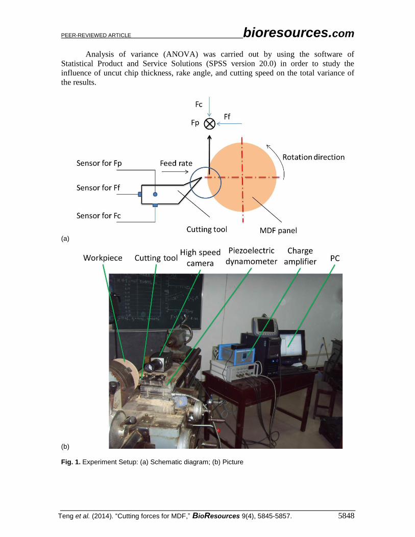
The samples were machined on a lathe machine with variable cutting speed and
feed rate, as shown in Fig. 1. The cutting forces were measured with a piezoelectric
dynamometer Kistler 9257 B coupled to a 5019 A charging amplifier and to a computer
fitted with an acquisition card and the software for signal treatment. When the cutting
tool cut the work piece, only the normal cutting forces (Fc) and the feed force (Ff) were
measured in this series cutting experiments.
A high speed camera, an i-speed 3 camera of Olympus with a frame rate of 4000
fps compared to the resolution of 912×684 and exposure time of 1/10000 s, was used to
record the machining process and chip form. Photos of chips produced in these
experiments were also taken and analyzed.
Plan of the experiment
A full factorial experimental design was established where the main variables
were the uncut chip thickness (h, three levels: 0.027, 0.1 and 0.61 mm), the rake angle of
tools (γf, three levels: 5, 15 and 30°), and the cutting speed (vc, three levels: 0.84, 1.67 and
3.36 m/s), as shown on Table 2.
Table 2. Assignment of Levels to Factors
Level Uncut chip thickness h
[mm] Rake angle γf [°] Cutting speed vc [m/s]
1 0.027 5 0.84 [80 r/min]
2 0.1 15 1.67 [160 r/min]
3 0.61 30 3.36 [320 r/min]
PEER-REVIEWED ARTICLE bioresources.com
Teng et al. (2014). “Cutting forces for MDF,” BioResources 9(4), 5845-5857. 5848
Analysis of variance (ANOVA) was carried out by using the software of
Statistical Product and Service Solutions (SPSS version 20.0) in order to study the
influence of uncut chip thickness, rake angle, and cutting speed on the total variance of
the results.
(a)
(b) Fig. 1. Experiment Setup: (a) Schematic diagram; (b) Picture

PEER-REVIEWED ARTICLE bioresources.com
Teng et al. (2014). “Cutting forces for MDF,” BioResources 9(4), 5845-5857. 5849
RESULTS AND DISCUSSION Analysis of Normal Cutting Force Influence of uncut chip thickness, rake angle, and cutting speed on the normal cutting
force Table 3 shows the results of both of the normal cutting force and feed force for
the full factorial experiment.
Table 3. Full Factorial Experimental Plan
Test No. h [mm] γf [°] vc [m/s] Fc [N/mm] Ff [N/mm]
1 0.027 5 0.84 56.12 162.1
2 0.027 5 1.67 87.86 91.86
3 0.027 5 3.36 87.79 92.05
4 0.027 15 0.84 24.66 141.1
5 0.027 15 1.67 42.48 65.12
6 0.027 15 3.36 43.61 66.15
7 0.027 30 0.84 27.11 116.1
8 0.027 30 1.67 49 69.6
9 0.027 30 3.36 44.9 68.97
10 0.1 5 0.84 73.52 88.89
11 0.1 5 1.67 83.71 105.1
12 0.1 5 3.36 87.67 98.44
13 0.1 15 0.84 21.02 162.4
14 0.1 15 1.67 51.17 92.86
15 0.1 15 3.36 43.02 78.28
16 0.1 30 0.84 45.37 76.98
17 0.1 30 1.67 39.38 69.6
18 0.1 30 3.36 55.49 71.65
19 0.61 5 0.84 49.9 220.7
20 0.61 5 1.67 50.12 226.8
21 0.61 5 3.36 58.02 229.9
22 0.61 15 0.84 14.57 207.5
23 0.61 15 1.67 13.02 189.1
24 0.61 15 3.36 7.47 225.8
25 0.61 30 0.84 17.07 182.7
26 0.61 30 1.67 15.94 181.2
27 0.61 30 3.36 12.18 189.7
Notes: Normal Cutting Force (Fc), Feed Force (Ff)

PEER-REVIEWED ARTICLE bioresources.com
Teng et al. (2014). “Cutting forces for MDF,” BioResources 9(4), 5845-5857. 5850
Figure 2 shows the normal cutting force of different cutting speed changes with
the changes of rake angle (γf) and chip thickness (h).
It can be seen that in Fig. 2, at a comparatively high cutting speed, higher than
1.67 m/s in this test, the normal cutting force had little connection with the cutting speed.
Moreover, lines in Fig. 2 with the cutting speed of 1.67 and 3.36 m/s indicated that the
normal cutting force increased approximately linearly with the increasing of the uncut
chip thickness (h) and decreased slightly with the increasing of rake angle (γf).
However, when the cutting speed was at a very low level (0.84 m/s in Fig. 2), the
normal cutting force changed dramatically with the increasing of uncut chip thickness
(h). The reason may be explained by the study of Dippon et al. (2000), which showed
that the pressure exerted by an uncut chip on the rake face mainly dominated the force on
the rake face.
With the small chip thickness, low cutting speed, and the elasticity of the MDF
fiber itself together with the adhesive used in the MDF manufacturing process, chips are
not very easy to fracture and connect with the uncut chip, and this factor tends to
strengthen the normal cutting force.
Fig. 2. Effect of parameters on normal cutting force of MDF in orthogonal cutting
ANOVA for Normal cutting force
The analysis of variance was carried out in order to acquire the statistical
significance of the variables (h, vc, γf) and their interactions on the normal cutting force in
orthogonal cutting of MDF panels for a level of significance of 5%.
As shown in Table 4, for the MDF cutting, uncut chip thickness, cutting speed,
rake angle, together with the interaction between chip thickness and cutting speed had
statistical contributions on the normal cutting force, according to the p-value of less than
0.05 and the F-value of greater than the F0.05.

PEER-REVIEWED ARTICLE bioresources.com
Teng et al. (2014). “Cutting forces for MDF,” BioResources 9(4), 5845-5857. 5851
Table 4. Results of ANOVA for Normal Cutting Force
Source SS Df MS F Sig. F0.05
h 73348.262 2 36674.131 140.395 0.000 5.14 *
vc 4767.202 2 2383.601 9.125 0.009 5.14 *
γf 4892.830 2 2446.415 9.365 0.008 5.14 *
h * vc 5033.557 4 1258.389 4.817 0.028 4.53 *
h * γf 1513.401 4 378.350 1.448 0.303 4.53 NS
vc * γf 1609.928 4 402.482 1.541 0.279 4.53 NS
Error 2089.767 8 261.221
Total 565460.187 26
R2= 99.6% ; R2(Adj) = 98.8%; * Significant; NS non-significant SS - Sum of Squares; MS – Mean Square; Sig - Significance
Analysis of Feed Force ANOVA for Feed force
The analysis of variance was carried out in order to acquire the statistical
significance of the variables (h, vc, γf) and their interactions on the feed force in
orthogonal cutting of MDF panels for a level of significance of 5%.
Table 5. Results of ANOVA for Feed Force
Source SS Df MS F Sig. F0.05
h 4472.749 2 2236.374 52.302 0.000 5.14 *
γf 9239.570 2 4619.785 108.043 0.000 5.14 *
vc 852.363 2 426.182 9.967 0.007 5.14 *
h * γf 24.921 4 6.230 0.146 0.960 4.53 NS
h * vc 623.216 4 155.804 3.644 0.056 4.53 NS
γf * vc 158.740 4 39.685 0.928 0.494 4.53 NS
Error 342.070 8 42.759
Total 69240.025 26
R2 = 97.8% ; R2(Adj) = 92.9%; * Significant; NS non-significant SS - Sum of Squares; MS – Mean Square; Sig - Significance
Table 5 shows the results of ANOVA analysis for the feed force. As can be seen
in Table 5, uncut chip thickness, cutting speed, and rake angle had statistical significance
with respect to the feed force, since p-value of these factors was less than 0.05, and the F-
value of these factors was greater than F0.05.
Influence of uncut chip thickness, rake angle, and cutting speed on the feed force
Figure 3 shows the feed force of different cutting speed changes with the changes
of rake angle (γf) and chip thickness (h).

PEER-REVIEWED ARTICLE bioresources.com
Teng et al. (2014). “Cutting forces for MDF,” BioResources 9(4), 5845-5857. 5852
Fig. 3. Effect of parameters on feed force of MDF in orthogonal cutting
From Fig. 3 it can be seen that, with the increasing of the rake angle, the feed
force of MDF cutting mainly decreased in magnitude at the beginning and then changed
slightly. Take the cutting speed of 1.67 m/s for example, the feed force was decreased by
more than 30 N, with the rake angle changing from 5o to 15o, and then changed less than
10 N, though the rake angle changed from 15o to 30o. This may be the reason that with
rising of rake angle, the chip contact area changed, which is in agreement with the study
of Costes et al. (2003), indicating that the cutting edge was loaded most within 0.1 mm,
and diminished almost completely after 0.25 mm when machining MDF.
It can also be found that, at the uncut chip thickness less than 0.1 mm in this test,
there were little differences found on feed force when the uncut chip thickness changed.
Meanwhile, the uncut chip thickness increased more than 0.1 mm (0.61 mm in this
experiment), and the feed force decreased obviously, especially under the large cutting
speed (cutting speed of 3.36 m/s for example). This revealed that the chip thickness had
great contributions on the feed force.
Analysis of Chip Morphology
The MDF cutting process is mainly influenced by fracture and compression of
MDF chips between the incoming material and the rake angle of tool (Costes et al. 2003).
Hence, the chip morphology was studied in this experiment. In the present work, the
resulting chip form was obviously influenced by the cutting conditions. Photos of the
typical moments recorded during the chip forming process at uncut chip thickness of
0.027, 0.1, and 0.61 mm, respectively, at rake angle of 5, 15, and 30°, respectively, at
cutting speed 0.84, 1.67, and 3.36 m/s, respectively, are shown in Table 6(a, b, c).
From Table 6(a, b, c) it is apparent that the forming process of all kinds of chips
can be clearly captured. Like Table 6(c), the coiled chip type can be easily found in the
picture. All kinds of chip morphology can also be divided by using the pictures taken by
high speed camera, which will be explained in the following pages.

PEER-REVIEWED ARTICLE bioresources.com
Teng et al. (2014). “Cutting forces for MDF,” BioResources 9(4), 5845-5857. 5853
Table 6a. Photos by i-SPEED Camera at Uncut Chip Thickness of 0.027 mm
vc γf 5° 15° 30°
0.84 m/s
1.67 m/s
3.36 m/s
Table 6b. Photos by i-SPEED Camera at Uncut Chip Thickness of 0.1 mm
vc γf 5° 15° 30°
0.84 m/s
1.67 m/s
3.36 m/s

PEER-REVIEWED ARTICLE bioresources.com
Teng et al. (2014). “Cutting forces for MDF,” BioResources 9(4), 5845-5857. 5854
Table 6c. Photos by i-SPEED Camera at Uncut Chip Thickness of 0.61 mm
vc γf 5° 15° 30°
0.84 m/s
1.67 m/s
3.36 m/s
When cutting the MDF panel, various types of chips obtained for the full factorial
experiment can be divided into three typical chip forms, namely coiled chip, granular
chip, and dust. Typical examples of all these three classified chip forms are shown in Fig.
4 by the usage of the photos of macroscopic view. The coiled chip (Fig. 4(a, b)) is the one
that continuous chip formed into one roll or two rolls connected with each other. The
granular chip (Fig. 4(c, d)) is the one that continuous chip splits into pieces, and these
small chip pieces are easy to break out into more tiny particles. The dust (Fig. 4(e, f))
includes those chips that cannot be clearly classified because of their small sizes.
a b
Fig. 4 (a, b). Photos of Macroscopic View of Classified Chip Form Examples of Coiled Chip (a, b) γf = 30°, h = 0.61 mm, vc = 0.84 m/s
PEER-REVIEWED ARTICLE bioresources.com
Teng et al. (2014). “Cutting forces for MDF,” BioResources 9(4), 5845-5857. 5855
C D
e f
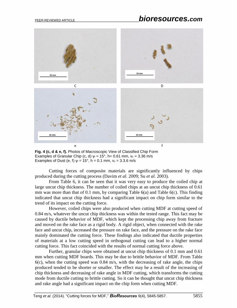
Fig. 4 (c, d & e, f). Photos of Macroscopic View of Classified Chip Form Examples of Granular Chip (c, d) γf = 15°, h= 0.61 mm, vc = 3.36 m/s Examples of Dust (e, f) γf = 15°, h = 0.1 mm, vc = 3.3.6 m/s
Cutting forces of composite materials are significantly influenced by chips
produced during the cutting process (Davim et al. 2009; Su et al. 2003).
From Table 6, it can be seen that it was very easy to produce the coiled chip at
large uncut chip thickness. The number of coiled chips at an uncut chip thickness of 0.61
mm was more than that of 0.1 mm, by comparing Table 6(a) and Table 6(c). This finding
indicated that uncut chip thickness had a significant impact on chip form similar to the
trend of its impact on the cutting force.
However, coiled chips were also produced when cutting MDF at cutting speed of
0.84 m/s, whatever the uncut chip thickness was within the tested range. This fact may be
caused by ductile behavior of MDF, which kept the processing chip away from fracture
and moved on the rake face as a rigid body. A rigid object, when connected with the rake
face and uncut chip, increased the pressure on rake face, and the pressure on the rake face
mainly dominated the cutting force. These findings also indicated that ductile properties
of materials at a low cutting speed in orthogonal cutting can lead to a higher normal
cutting force. This fact coincided with the results of normal cutting force above.
Further, granular chips were obtained at uncut chip thickness of 0.1 mm and 0.61
mm when cutting MDF boards. This may be due to brittle behavior of MDF. From Table
6(c), when the cutting speed was 0.84 m/s, with the decreasing of rake angle, the chips
produced tended to be shorter or smaller. The effect may be a result of the increasing of
chip thickness and decreasing of rake angle in MDF cutting, which transforms the cutting
mode from ductile cutting to brittle cutting. So it can be thought that uncut chip thickness
and rake angle had a significant impact on the chip form when cutting MDF.

PEER-REVIEWED ARTICLE bioresources.com
Teng et al. (2014). “Cutting forces for MDF,” BioResources 9(4), 5845-5857. 5856
CONCLUSIONS
1. Statistical results indicated that the changes of rake angle, uncut chip thickness (feed
rate), cutting speed, and the interaction of uncut chip thickness and cutting speed had
very significant influence on the normal cutting force, while the variations of
interaction of rake angle and uncut chip thickness, as well as interaction of rake angle
and cutting speed made little contribution to it.
2. Statistical results indicated that the changes of rake angle, uncut chip thickness (feed
rate), and cutting speed greatly influenced the normal cutting force, while the
variations of interactions of rake angle, uncut chip thickness, and cutting speed,
respectively, had little contributions to it.
3. Chip forms of MDF cutting could be divided into three typical types. Low cutting
speed or high chip thickness tended to produce coiled chips. Granular chips were
more likely obtained at large chip thickness and small rake angle.
ACKNOWLEDGEMENTS
The authors are grateful for the support from the Project Funded by Priority
Academic Program Development of Jiangsu Higher Education Institutions (PAPD), Key
Projects in China National Science and Technology Pillar Program during the Twelfth
Five-year Plan Period (2012BAD24B01).
REFERENCES CITED
Aguilera, A. (2009). "Cutting energy and surface roughness in medium density fiberboard
rip sawing," European Journal of Wood and Wood Products 69(1), 11-18. doi:
10.1007/s00107-009-0396-z
Aguilera, A. (2011). "Surface roughness evaluation in medium density fibreboard rip
sawing," European Journal of Wood and Wood Products 69(3), 489-493. doi:
10.1007/s00107-010-0481-3
Aguilera, A., and Barros, J. L. (2011). "Surface roughness assessment on medium density
fibreboard rip sawing using acoustic signals," European Journal of Wood and Wood
Products 70(1-3), 369-372. doi: 10.1007/s00107-011-0528-0
Aguilera, A., Meausoone, P. J., and Martin, P. (2000). "Wood material influence in
routing operations: the MDF case," Holz Als Roh-Und Werkstof 58, 278-283.
Bhattacharyya, D., Allen, M. N., and Mander, S. J. (1993). "Cryogenic machining of
Kevlar composites," Master. Manuf. Process 8, 631-652.
Boucher, J., M´eausoone, P. J., Martin, P., Auchet, S., and Perrin, L. (2007). "Influence of
helix angle and density variation on the cutting force in wood-based products
machining," Journal of Materials Processing Technology 189, 211-218.
Costes, J. P., Deces-Petit, C., Altintas, Y., and Ko, P. (2003). "Estimated stress and friction
distributions on tool rake face in the medium density fiberboard cutting process,"
Forest Products Journal 53(11-12), 59-66.
Davim, J. P., Gaitonde, V. N., and Karnik, S. R. (2007a). "An investigative study of
delamination in drilling of medium density fibreboard (MDF) using response surface

PEER-REVIEWED ARTICLE bioresources.com
Teng et al. (2014). “Cutting forces for MDF,” BioResources 9(4), 5845-5857. 5857
models," The International Journal of Advanced Manufacturing Technology 37(1-2),
49-57. doi: 10.1007/s00170-007-0937-8
Davim, J. P., Clemente, V., and Silva, S. (2007b). "Evaluation of delamination in drilling
medium density fibreboard," Proceedings of the Institution of Mechanical Engineers
Part B-Journal of Engineering Manufacture 221(4), 655-658. doi:
10.1243/09544054jem781
Davim, J. P., Clemente, V. C., and Silva, S. (2008). "Surface roughness aspects in milling
MDF (medium density fibreboard)," The International Journal of Advanced
Manufacturing Technology 40(1-2), 49-55. doi: 10.1007/s00170-007-1318-z
Davim, J. P., Silva, L. R., Festas, A., and Abrão, A. M. (2009). "Machinability study on
precision turning of PA 66 polyamide with and without glass fiber reinforcing,"
Materials & Design 30(2), 228-234.
Dippon, J., Ren, H., Amara, F. B., and Altintas, Y. (2000). "Orthogonal cutting mechanics
of medium density fiberboards," Forest Products Journal 50, 25-30.
Gaitonde, V. N., Karnik, S. R., and Davim, J. P. (2008a). "Prediction and minimization of
delamination in drilling of medium-density fiberboard (MDF) using response surface
methodology and Taguchi design," Materials and Manufacturing Processes 23(3-4),
377-384. doi: 10.1080/10426910801938379
Gaitonde, V. N., Karnik, S. R., and Davim, J. P. (2008b). "Taguchi multiple-performance
characteristics optimization in drilling of medium density fibreboard (MDF) to
minimize delamination using utility concept," Journal of Materials Processing
Technology 196(1-3), 73-78. doi: 10.1016/j.jmatprotec.2007.05.003
Guo, X., Ekevad, M., Marklund, B., Li, R., Cao, P., and Grönlund, A. (2014). "Cutting
forces and chip morphology during wood plastic composites orthogonal cutting,"
BioResources 9(2), 2090-2106.
Koch, P. (1964). Wood Machining Process, Ronald Press.
Lin, R. J. T., Houts, J. V., and Bhattacharyya, D. (2006). "Machinability investigation of
medium-density fibreboard," Holzforschung 60, 71-77.
Michaud, F. (2003). "Rhéologie de panneaux composites bois/thermoplastiques sous
chargement thermomécanique: aptitude au postformage," Ph.D. Thesis, Laval
University, Quebec, 2003.
Penman, D., Olsson, O. J., and Bowman, C. C. (1993). "Automatic inspection of
reconstituted wood panels for surface defects," Proc. SPIE 1823, 284-292.
Su, W. C., Wang, Y., Zhu, N., and Tanaka, C. (2003). "Effect of tool angles on the chips
generated during milling of wood by straight router –bits," Journal of Wood Science
49(3), 271-274.
Article submitted: May 5, 2014; Peer review completed: June 18, 2014; Revised version
received and accepted: July 26, 2014; Published: August 7, 2014.