Embed Size (px)
Citation preview
DIESEL Engine Fire Pump ControllersFeatures
1-1
For more information visit: www.chfire.com BR05805068K/B
FD100 Diesel Engine Controllers
September 2007
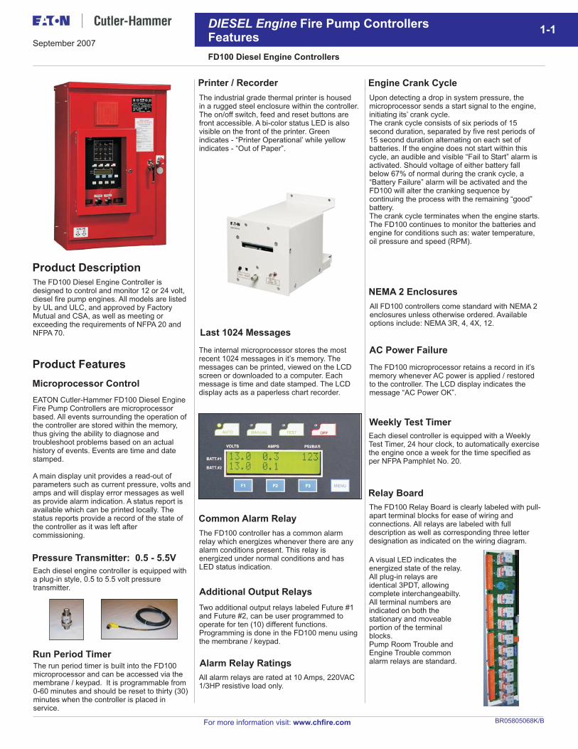
Last 1024 Messages
Printer / Recorder
The industrial grade thermal printer is housedin a rugged steel enclosure within the controller.The on/off switch, feed and reset buttons arefront accessible. A bi-color status LED is alsovisible on the front of the printer. Greenindicates - “Printer Operational’ while yellowindicates - “Out of Paper”.
Product Features
Microprocessor Control
EATON Cutler-Hammer FD100 Diesel EngineFire Pump Controllers are microprocessorbased. All events surrounding the operation ofthe controller are stored within the memory,thus giving the ability to diagnose andtroubleshoot problems based on an actualhistory of events. Events are time and datestamped.
A main display unit provides a read-out ofparameters such as current pressure, volts andamps and will display error messages as wellas provide alarm indication. A status report isavailable which can be printed locally. Thestatus reports provide a record of the state ofthe controller as it was left aftercommissioning.
Product Description
The FD100 Diesel Engine Controller isdesigned to control and monitor 12 or 24 volt,diesel fire pump engines. All models are listedby UL and ULC, and approved by FactoryMutual and CSA, as well as meeting orexceeding the requirements of NFPA 20 andNFPA 70.
Pressure Transmitter: 0.5 - 5.5V
Each diesel engine controller is equipped witha plug-in style, 0.5 to 5.5 volt pressuretransmitter.
Run Period TimerThe run period timer is built into the FD100microprocessor and can be accessed via themembrane / keypad. It is programmable from0-60 minutes and should be reset to thirty (30)minutes when the controller is placed inservice.
The internal microprocessor stores the mostrecent 1024 messages in it’s memory. Themessages can be printed, viewed on the LCDscreen or downloaded to a computer. Eachmessage is time and date stamped. The LCDdisplay acts as a paperless chart recorder.
Common Alarm Relay
The FD100 controller has a common alarmrelay which energizes whenever there are anyalarm conditions present. This relay isenergized under normal conditions and hasLED status indication.
Two additional output relays labeled Future #1and Future #2, can be user programmed tooperate for ten (10) different functions.Programming is done in the FD100 menu usingthe membrane / keypad.
All alarm relays are rated at 10 Amps, 220VAC1/3HP resistive load only.
Additional Output Relays
Alarm Relay Ratings
A visual LED indicates theenergized state of the relay.All plug-in relays areidentical 3PDT, allowingcomplete interchangeabilty.All terminal numbers areindicated on both thestationary and moveableportion of the terminalblocks.Pump Room Trouble andEngine Trouble commonalarm relays are standard.
Upon detecting a drop in system pressure, themicroprocessor sends a start signal to the engine,initiating its’ crank cycle.The crank cycle consists of six periods of 15second duration, separated by five rest periods of15 second duration alternating on each set ofbatteries. If the engine does not start within thiscycle, an audible and visible “Fail to Start” alarm isactivated. Should voltage of either battery fallbelow 67% of normal during the crank cycle, a“Battery Failure” alarm will be activated and theFD100 will alter the cranking sequence bycontinuing the process with the remaining “good”battery.The crank cycle terminates when the engine starts.The FD100 continues to monitor the batteries andengine for conditions such as: water temperature,oil pressure and speed (RPM).
Engine Crank Cycle
Relay Board
The FD100 Relay Board is clearly labeled with pull-apart terminal blocks for ease of wiring andconnections. All relays are labeled with fulldescription as well as corresponding three letterdesignation as indicated on the wiring diagram.
NEMA 2 Enclosures
All FD100 controllers come standard with NEMA 2enclosures unless otherwise ordered. Availableoptions include: NEMA 3R, 4, 4X, 12.
AC Power Failure
The FD100 microprocessor retains a record in it’smemory whenever AC power is applied / restoredto the controller. The LCD display indicates themessage “AC Power OK”.
Weekly Test Timer
Each diesel controller is equipped with a WeeklyTest Timer, 24 hour clock, to automatically exercisethe engine once a week for the time specified asper NFPA Pamphlet No. 20.
Product Features
Battery Chargers
DIESEL Engine Fire Pump ControllersFeatures
1-2
FD100 Diesel Engine Controllers
September 2007
For more information visit: www.chfire.com
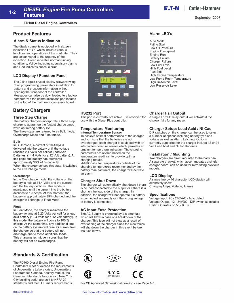
Alarm LED’s
Auto ModeFail to StartLow Oil PressureEngine OverspeedEngine RunBattery FailureCharger FailureLow Fuel LevelHigh Fuel LevelFuel SpillHigh Engine TemperatureLow Pump Room TemperatureHigh Reservoir LevelLow Reservoir Level
Alarm & Status Indication
LCD Display / Function Panel
The display panel is equipped with sixteenindication LED’s which
colour keyed to the urgency of theindication. Green indicates normal runningconditions, Yellow indicates supervisory alarmsand Red indicates critical alarms.
indicate variousfunctions and operations of the controller. Theyare
The 2 line liquid crystal display allows viewingof all programming parameters in addition tobattery and pressure information withoutopening the front door of the controller.Messages can also be downloaded to a laptopcomputer via the communications port locatedon the top of the main microprocessor board.
BR05805068K/B
Three Step ChargeThe battery chargers incorporate a three stepcharge to guarantee the fastest charge timeswhile optimizing battery life.The three steps are referred to as Bulk mode,Overcharge Mode and Float mode.
In Bulk mode, a current of 10 Amps isdelivered into the battery until the voltagereaches 2.4 Volts per cell for Lead AcidBatteries. (14.4 Volts for a 12 Volt battery). Atthis point, the battery has recoveredapproximately 90% of its capacity.When the charger senses this state, it switchesto the Overcharge mode.
In the Overcharge mode, the voltage on thebattery is held at 14.4 Volts and the currentinto the battery declines. This mode ismaintained until the current into the batterydeclines to 1.5 Amps. At this moment, thebattery is approximately 99% charged and thecharger will change to Float Mode.
In Float Mode, the charger maintains thebattery voltage at 2.23 Volts per cell for a leadacid battery (13.4 Volts for a 12 Volt battery). Inthis mode, the battery will come to 100 %charge. At the same time, any additional loadon the battery system will draw its current fromthe charger so that the battery will notdischarge due to these additional loads.This charging technique insures that thebattery will not be overcharged.
Bulk
Overcharge
Float
RS232 Port
Temperature Monitoring
Charger Shut Down
AC Input Fuse Protection
This port is currently not active. It is reserved foruse with the Diesel Plus controller.
To achieve optimal performance of the chargerand to insure that the batteries are notovercharged, each charger is equipped with aninternal temperature sensor which provides anambient temperature indication. The chargingparameters are altered based on thetemperature readings, to provide optimalcharging results.Additionally, for temperatures outside of thecharging temperatures recommended by thebattery manufacturers, the charger will activatean alarm.
The charger will automatically shut down if thereis no load connected to the output or if there is ashort on the load side of the charger. Inaddition, the charger will not operate if a batteryis connected incorrectly or if the wrong voltageof battery is connected.
The AC Supply is protected by a 6 amp fusewhich will blow in case of a breakdown of thecharger. This fuse will not blow as a result ofoverloading of the charger since the electronicswill shutdown the charger in this event beforethe fuse blows.
Internal Temperature Sensor
Charger Fail Output
Charger Setup: Lead Acid / Ni Cad
Installation / Mounting
LCD Display
Specifications
A single Form C relay output will activate if thecharger fails for any reason.
DIP switches on the charger can be used to selecta number of options including battery type andvoltage as well as Alarm Latching. Optionscurrently supported for the charger include 12 or 24Volt Lead Acid and NiCad Batteries.
Two chargers are direct mounted to the back pan.A separate bracket, which accommodates a singlecharger board, can be used for retro-fitting previousmodels.
A single line by 16 character LCD display willalternately show:Charging Amps; Voltage; Alarms
Voltage Input: 90 - 240VAC - Auto detectVoltage Output: 12 - 24VDC - DIP switch selectableHertz: Operates on 50 / 60Hz
Standards & Certification
The FD100 Diesel Engine Fire PumpControllers meet or exceed the requirementsof Underwriters Laboratories, UnderwritersLaboratories Canada, Factory Mutual, theCanadian Standards Association, New YorkCity building code, are built to NFPA 20standards and meet CE mark requirements.
N. Y. C.APPROVED
For CE Approved Dimensional drawing - see Page 1-5.
6.64 [169]
1.23 [31]
22.17 [563]
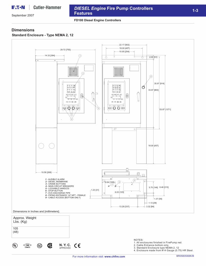
1 - AUDIBLE ALARM2 - DIESEL MEMBRANE3 - CRANK BUTTONS4 - MAIN CIRCUIT BREAKERS5 - LOCKABLE HANDLES6 - STOP BUTTON7 - DVS DISCHARGE PIPE8 - PIPING ENTRANCE 1/4" NPT - FEMALE9 - CABLE ACCESS (BOTTOM ONLY)
10.56 [268]
29.72 [755]
14.33 [364]
CRANK # 1CB1 CRANK # 2 CB2
35.97 [914]
53.97 [1371]
33.97 [863]
1.37 [35]
8.48 [215]5.75 [146]
1.13 [29]
3.32 [84]13.29 [337]
6.03 [153]
18.00 [457]
CRANK # 1CB1 CRANK # 2 CB2
18.00 [457]
10.00 [254]
2.00 [51]
Dimensions
For more information visit: www.chfire.com
1-3
Standard Enclosure - Type NEMA 2, 12
DIESEL Engine Fire Pump ControllersFeatures
FD100 Diesel Engine Controllers
NOTES:1. All enclosures finished in FirePump red.2. Cable Entrance bottom only.3. Standard Enclosure type NEMA 2, 124. Enclosure made from #14 Gauge (0.75) HR Steel.
Approx. WeightLbs. (Kg)
105(48)
N. Y. C.APPROVED
Dimensions in Inches and [millimeters].
September 2007
BR05805068K/B
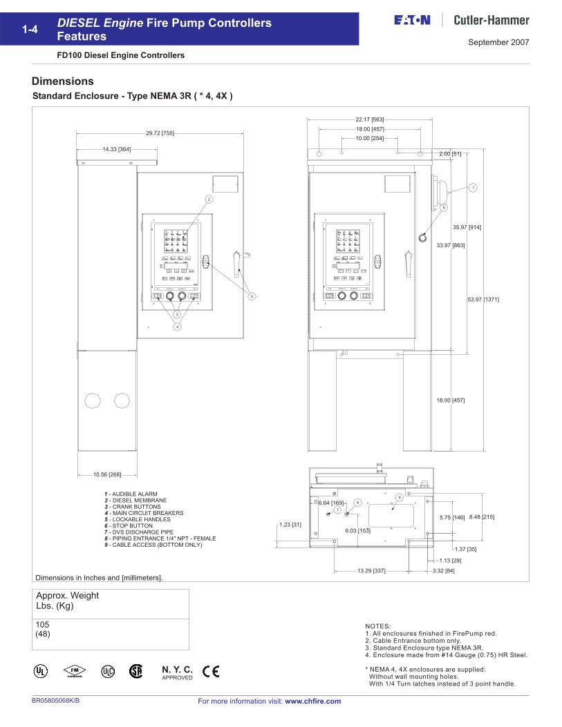
Dimensions
For more information visit: www.chfire.com
1-4
Standard Enclosure - Type NEMA 3R ( * 4, 4X )
DIESEL Engine Fire Pump ControllersFeatures
FD100 Diesel Engine Controllers
NOTES:1. All enclosures finished in FirePump red.2. Cable Entrance bottom only.3. Standard Enclosure type NEMA 3R.4. Enclosure made from #14 Gauge (0.75) HR Steel.
* NEMA 4, 4X enclosures are supplied:Without wall mounting holes.With 1/4 Turn latches instead of 3 point handle.
Approx. WeightLbs. (Kg)
105(48)
N. Y. C.APPROVED
Dimensions in Inches and [millimeters].
September 2007
BR05805068K/B
14.33 [364]
29.72 [755]
22.17 [563]
33.97 [863]
1 - AUDIBLE ALARM2 - DIESEL MEMBRANE3 - CRANK BUTTONS4 - MAIN CIRCUIT BREAKERS5 - LOCKABLE HANDLES6 - STOP BUTTON7 - DVS DISCHARGE PIPE8 - PIPING ENTRANCE 1/4" NPT - FEMALE9 - CABLE ACCESS (BOTTOM ONLY)
10.00 [254]
2.00 [51]
18.00 [457]
53.97 [1371]
18.00 [457]
10.56 [268]
35.97 [914]
1.23 [31]
6.64 [169]
6.03 [153]
13.29 [337] 3.32 [84]
1.13 [29]
5.75 [146] 8.48 [215]
1.37 [35]
CRANK # 1CB1 CRANK # 2 CB2 CRANK # 1CB1 CRANK # 2 CB2
1
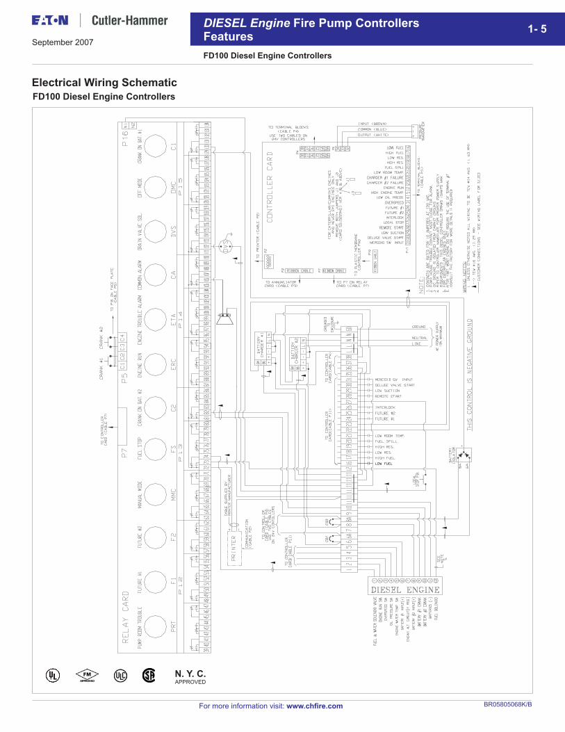
Electrical Wiring Schematic
For more information visit: www.chfire.com
N. Y. C.APPROVED
FD100 Diesel Engine Controllers
FD100 Diesel Engine Controllers
DIESEL Engine Fire Pump ControllersFeatures
1- 5September 2007
BR05805068K/B
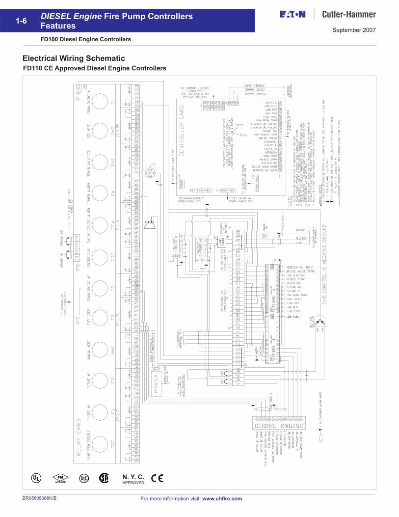
Electrical Wiring Schematic
For more information visit: www.chfire.com
N. Y. C.APPROVED
FD110 CE Approved Diesel Engine Controllers
FD100 Diesel Engine Controllers
DIESEL Engine Fire Pump ControllersFeatures
1-6September 2007
BR05805068K/B
For more information visit: www.chfire.com
N. Y. C.APPROVED
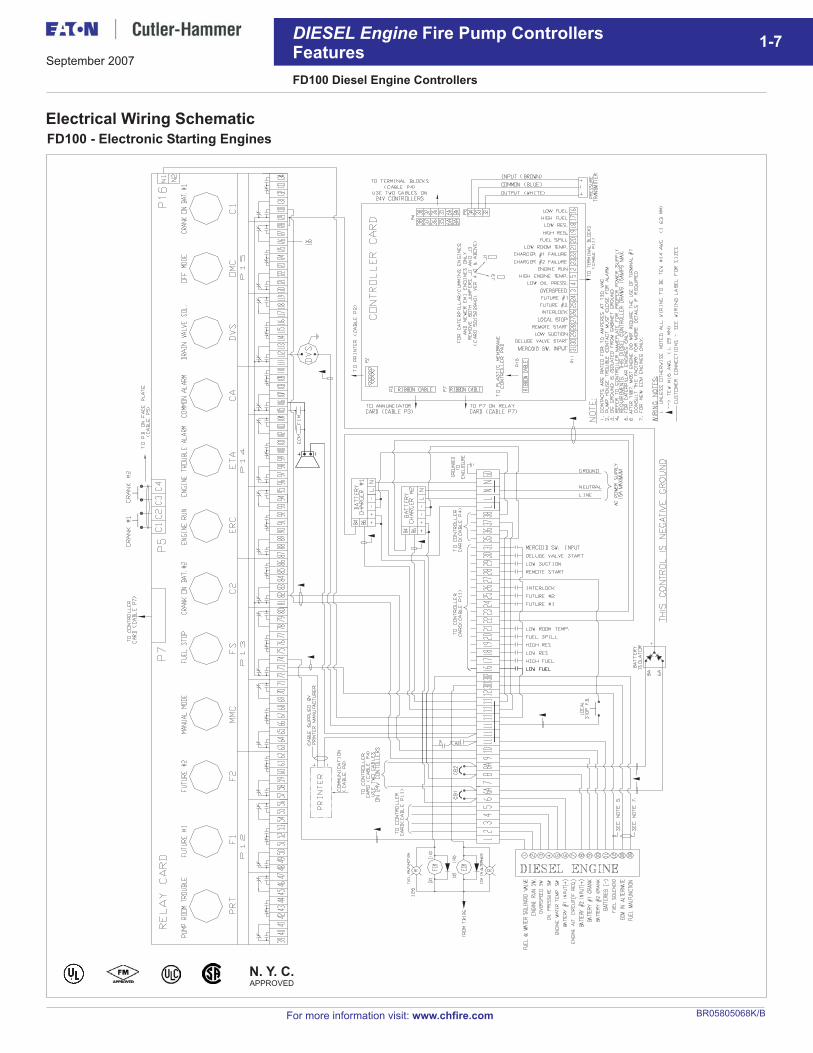
Electrical Wiring Schematic
FD100 - Electronic Starting Engines
FD100 Diesel Engine Controllers
DIESEL Engine Fire Pump ControllersFeatures
1-7September 2007
BR05805068K/B
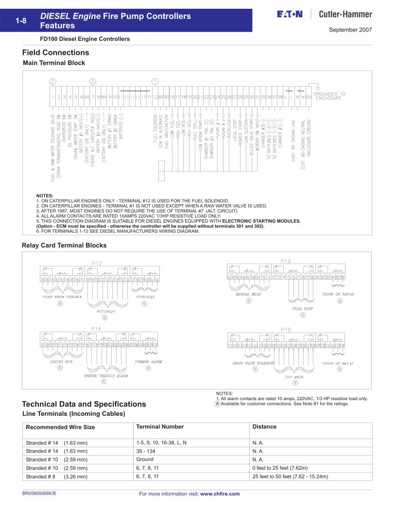
Field Connections
Relay Card Terminal Blocks
Main Terminal Block
For more information visit: www.chfire.com
NOTES:1. ON CATERPILLAR ENGINES ONLY - TERMINAL #12 IS USED FOR THE FUEL SOLENOID.2. ON CATERPILLAR ENGINES - TERMINAL #1 IS NOT USED EXCEPT WHEN A RAW WATER VALVE IS USED.3. AFTER 1987, MOST ENGINES DO NOT REQUIRE THE USE OF TERMINAL #7. (ALT. CIRCUIT)4. ALL ALARM CONTACTS ARE RATED 10AMPS 220VAC 1/3HP RESISTIVE LOAD ONLY.5. THIS CONNECTION DIAGRAM IS SUITABLE FOR DIESEL ENGINES EQUIPPED WITH
6. FOR TERMINALS 1-12 SEE DIESEL MANUFACTURERS WIRING DIAGRAM.
ELECTRONIC STARTING MODULES.(Option - ECM must be specified - otherwise the controller will be supplied without terminals 301 and 302).
Technical Data and Specifications
Line Terminals (Incoming Cables)
Recommended Wire Size
Stranded # 14 (1.63 mm)
Stranded # 14 (1.63 mm)
Stranded # 10 (2.59 mm)
Stranded # 10 (2.59 mm)
Stranded # 8 (3.26 mm)
Terminal Number
1-5, 9, 10, 16-38, L, N
39 - 134
Ground
6, 7, 8, 11
6, 7, 8, 11
Distance
N. A.
N. A.
N. A.
0 feet to 25 feet (7.62m)
25 feet to 50 feet (7.62 - 15.24m)
NOTES:1. All alarm contacts are rated 10 amps, 220VAC, 1/3 HP resistive load only.8 Available for customer connections. See Note #1 for the ratings.
FD100 Diesel Engine Controllers
DIESEL Engine Fire Pump ControllersFeatures
1-8September 2007
BR05805068K/B
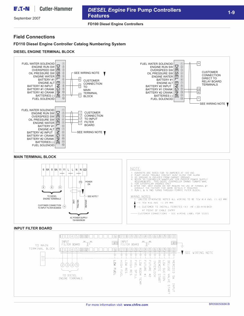
DIESEL ENGINE TERMINAL BLOCK
6 86A 8A 11 11 L L N N GD
6
TO DIESEL
ENGINE TERMINALS
AC POWER SUPPLY
15A MAXIMUM
POWER
ON
SEE NOTE 7
LIN
E
NE
UT
RA
L
GR
OU
NDCUSTOMER CONNECTION
TO INPUT FILTER BOARDS
8 11
11
PO
MAIN TERMINAL BLOCK
1
12
11
10
9
8
7
6
3
2
4
55
4
3
2
DIE
SE
LE
NG
INE
FUEL WATER SOLENOID
SEE WIRING NOTE
CUSTOMERCONNECTIONTO INPUTFILTERBOARD
ENGINE RUN SWOVERSPEED SW
OIL PRESSURE SWENGINE WATER
BATTERY #1ENGINE ALT
BATTERY #2 INPUTBATTERY #1 CRANKBATTERY #2 CRANK
BATTERIES (-)FUEL SOLENOID
Field Connections
FD110 Diesel Engine Controller Catalog Numbering System
For more information visit: www.chfire.com
FD100 Diesel Engine Controllers
DIESEL Engine Fire Pump ControllersFeatures
1-9
INPUT FILTER BOARD
1
12
11
10
9
8
7
6
74
130
82
11
5
4
3
2D
IES
EL
EN
GIN
EFUEL WATER SOLENOID
CUSTOMERCONNECTIONDIRECT TORELAY BOARDTERMINALS
ENGINE RUN SWOVERSPEED SW
OIL PRESSURE SWENGINE WATER
BATTERY #1ENGINE ALT
BATTERY #2 INPUTBATTERY #1 CRANKBATTERY #2 CRANK
BATTERIES (-)FUEL SOLENOID
1
12
11
10
9
8
7
6 6
8
11
5
4
3
2
DIE
SE
LE
NG
INE
FUEL WATER SOLENOID
SEE WIRING NOTE
CUSTOMERCONNECTIONTOMAINTERMINALBLOCK
ENGINE RUN SWOVERSPEED SW
OIL PRESSURE SWENGINE WATER
BATTERY #1ENGINE ALT
BATTERY #2 INPUTBATTERY #1 CRANKBATTERY #2 CRANK
BATTERIES (-)FUEL SOLENOID
SEE WIRING NOTE
September 2007
BR05805068K/B
For more information visit: www.chfire.com
FD100 Diesel Engine Controllers
DIESEL Engine Fire Pump ControllersFeatures
1-10
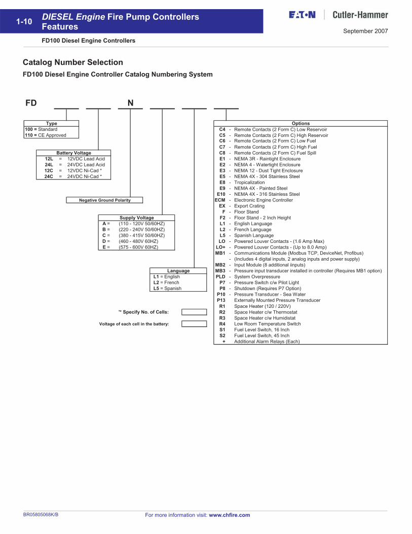
Catalog Number Selection
FD100 Diesel Engine Controller Catalog Numbering System
100 = Standard C4 - Remote Contacts (2 Form C) Low Reservoir
110 = CE Approved C5 - Remote Contacts (2 Form C) High ReservoirC6 - Remote Contacts (2 Form C) Low Fuel
C7 - Remote Contacts (2 Form C) High Fuel
C8 - Remote Contacts (2 Form C) Fuel Spill
12L = 12VDC Lead Acid E1 - NEMA 3R - Raintight Enclosure
24L = 24VDC Lead Acid E2 - NEMA 4 - Watertight Enclosure
12C = 12VDC Ni-Cad * E3 - NEMA 12 - Dust Tight Enclosure
24C = 24VDC Ni-Cad * E5 - NEMA 4X - 304 Stainless Steel
E8 - Tropicalization
E9 - NEMA 4X - Painted Steel
E10 - NEMA 4X - 316 Stainless Steel
Negative Ground Polarity ECM - Electronic Engine Controller
EX - Export Crating
F - Floor Stand
Supply Voltage F2 - Floor Stand - 2 Inch Height
A = (110 - 120V 50/60HZ) L1 - English Language
B = (220 - 240V 50/60HZ) L2 - French Language
C = (380 - 415V 50/60HZ) L5 - Spanish Language
D = (460 - 480V 60HZ) LO - Powered Louver Contacts - (1.6 Amp Max)
E = (575 - 600V 60HZ) LO+ - Powered Louver Contacts - (Up to 8.0 Amp)
MB1 - Communications Module (Modbus TCP, DeviceNet, Profibus)
- (Includes 4 digital inputs, 2 analog inputs and power supply)
MB2 - Input Module (8 additional iinputs)
MB3 - Pressure input transducer installed in controller (Requires MB1 option)
L1 = English PLD - System Overpressure
L2 = French P7 - Pressure Switch c/w Pilot Light
L5 = Spanish P8 - Shutdown (Requires P7 Option)
P10 - Pressure Transducer - Sea Water
P13 Externally Mounted Pressure Transducer
R1 Space Heater (120 / 220V)
R2 Space Heater c/w Thermostat
R3 Space Heater c/w Humidistat
Voltage of each cell in the battery: R4 Low Room Temperature Switch
S1 Fuel Level Switch, 16 Inch
S2 Fuel Level Switch, 45 Inch
+ Additional Alarm Relays (Each)
Options
'* Specify No. of Cells:
Language
NFD
Battery Voltage
Type
September 2007
BR05805068K/B
FD100 Diesel Engine Controllers
DIESEL Engine Fire Pump ControllersFeatures
1-11
For more information visit: www.chfire.com
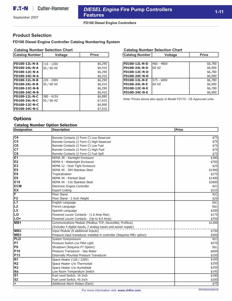
Product Selection
FD100 Diesel Engine Controller Catalog Numbering System
Options
Catalog Number Selection Chart Catalog Number Selection Chart
Catalog Number Price Catalog Number Price
FD100-12L-N-A $6,290 FD100-12L-N-D 460 - 480V $6,780
FD100-24L-N-A $6,410 FD100-24L-N-D 60 HZ $6,900
FD100-12C-N-A $6,290 FD100-12C-N-D $6,780
FD100-24C-N-A $6,410 FD100-24C-N-D $6,900
FD100-12L-N-B 220 - 240V $6,290 FD100-12L-N-E 575 - 600V $6,780
FD100-24L-N-B 50 / 60 HZ $6,410 FD100-24L-N-E 60 HZ $6,900
FD100-12C-N-B $6,290 FD100-12C-N-E $6,780
FD100-24C-N-B $6,410 FD100-24C-N-E $6,900
FD100-12L-N-C 380 - 415V $6,890
FD100-24L-N-C 50 / 60 HZ $7,010
FD100-12C-N-C $6,890
FD100-24C-N-C $7,010
Voltage
110 - 120V
50 / 60 HZ
Voltage
Catalog Number Option SelectionDesignation Description Price
C4 Remote Contacts (2 Form C) Low Reservoir $75
C5 Remote Contacts (2 Form C) High Reservoir $75
C6 Remote Contacts (2 Form C) Low Fuel $75
C7 Remote Contacts (2 Form C) High Fuel $75
C8 Remote Contacts (2 Form C) Fuel Spill $75
E1 NEMA 3R - Raintight Enclosure $380
E2 NEMA 4 - Watertight Enclosure $700
E3 NEMA 12 - Dust Tight Enclosure $25
E5 NEMA 4X - 304 Stainless Steel $1900
E8 Tropicalization $275
E9 NEMA 4X - Painted Steel $1400
E10 NEMA 4X - 316 Stainless Steel $3000
ECM Electronic Engine Controller N/C
EX Export Crating $525
F Floor Stand N/C
F2 Floor Stand - 2 Inch Height $25
L1 English Language Std.
L2 French Language Std.
L5 Spanish Language $200
LO Powered Louver Contacts - (1.6 Amp Max) $175
LO+ Powered Louver Contacts - (Up to 8.0 Amp) $350
MB1 Communications Module (Modbus TCP, DeviceNet, Profibus) $1200
(Includes 4 digital inputs, 2 analog inputs and power supply)
MB2 Input Module (8 additional iinputs) $750
MB3 Pressure input transducer installed in controller (Requires MB1 option) $500
PLD System Overpressure N/C
P7 Pressure Switch c/w Pilot Light $570
P8 Shutdown (Requires P7 Option) Std.
P10 Pressure Transducer - Sea Water $600
P13 Externally Mounted Pressure Transducer $250
R1 Space Heater (120 / 220V) $185
R2 Space Heater c/w Thermostat $250
R3 Space Heater c/w Humidistat $250
R4 Low Room Temperature Switch $145
S1 Fuel Level Switch, 16 Inch $180
S2 Fuel Level Switch, 45 Inch $200
+ Additional Alarm Relays (Each) $75
Note: Prices above also apply to Model FD110 - CE Approved units.
September 2007
BR05805068K/B
EATONCutler-Hammer2256 29th Street NE #10 Calgary, Alberta, T1Y 7G4Canadatel: 403-717-2000fax: 403-717-0567www.chfire.com
© 2007 Eaton CorporationAll Rights ReservedPrinted in CanadaPublication No.: BR05805068K/BSeptember 2007
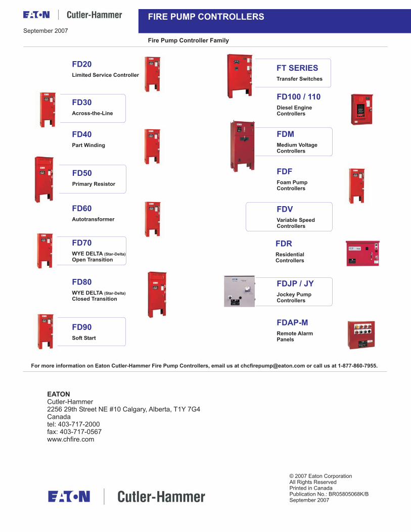
FIRE PUMP CONTROLLERS
Fire Pump Controller Family
For more information on Eaton Cutler-Hammer Fire Pump Controllers, email us at [email protected] or call us at 1-877-860-7955.
FD20
Limited Service Controller
FD30
Across-the-Line
FD40
Part Winding
FD50
Primary Resistor
FD60
Autotransformer
FD70
WYE DELTAOpen Transition
(Star-Delta)
FD80
WYE DELTAClosed Transition
(Star-Delta)
FD90
Soft Start
FDR
ResidentialControllers
FT SERIES
Transfer Switches
FDV
Variable SpeedControllers
FDF
Foam PumpControllers
FDM
Medium VoltageControllers
FDJP / JY
Jockey PumpControllers
FDAP-M
Remote AlarmPanels
FD100 / 110
Diesel EngineControllers
September 2007