Embed Size (px)
Citation preview

Cutes Corporation CT-2000 Series
IGBT INVERTER
Instruction
Head Office : 2-22, Nan Yuan Road, Chung Li City, Taiwan TEL: 886 3 4612333 or 886 3 4526161 ext. 275 FAX: 886 3 4526227 or 886 3 4511347 E-mail: [email protected] URL: www.cutes.com.tw

Introduction Thank you for choosing the CT-2000 inverter unit, this inverter unit is suitable for operating squirrel cage induction motors. Please read this instruction manual carefully before actual usage in order to ensure proper operation and suit your needs. Table of Contents 1. Inspection upon receiving 2. Installation and Storage 3. Application notes 4. Block diagram and Wiring 5. Operation Test 6. Function Setup and Specification 7. Description of alarm display indications 8. Troubleshooting 9. Maintenance and Inspection 10. Function code Table
11. Inspection upon receiving A. Check that the model, the capacity and power voltage specifications
are as ordered. B. Check that no damage has occurred during transportation. C. Check that none of the internal parts have been damaged or have
fallen off. D. Check that none of the connectors have been damaged or have fallen
off. E. Check that there is no loosening of the terminals or screws of each of
the parts. 2. Installation and Storage
A. Storage: If the equipment is not to be installed immediately, it should be stored in a
clean and dry location at ambient temperatures from 20℃to 55℃. The surrounding air must be free of corrosive contaminants.
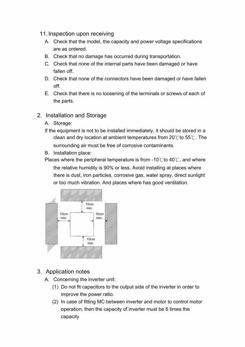
B. Installation place: Places where the peripheral temperature is from -10℃to 40℃, and where
the relative humidity is 90% or less. Avoid installing at places where there is dust, iron particles, corrosive gas, water spray, direct sunlight or too much vibration. And places where has good ventilation.
������������
���������������
������������������
��������������
10cmmin.
10cmmin.
10cmmin.
10cmmin.
3. Application notes
A. Concerning the inverter unit: (1) Do not fit capacitors to the output side of the inverter in order to
improve the power ratio. (2) In case of fitting MC between inverter and motor to control motor
operation, then the capacity of inverter must be 6 times the capacity

of motor. (3) Run a motor that is within the capacity of the inverter unit, light load
current and no-load current will cause the motor to develop ripple current.
(4) This unit is provided with a current limiting function. The starting torque is assumed to be from 80% to 120%.
B. Concerning the AC motor
(1) When general-purpose motors are operated at low speeds, there is a reduced cooling effect, please apply the special purpose motor.
(2) Operation at frequencies exceeding 60 Hz requires caution as there is the danger of the mechanical strength failure of the motor.
(3) When motors with brakes are being operated, the power for the brake and inverter should be taken from the same power supply and the brake operation must be in phase when the unit is started and stopped.
4. Block diagram, Wiring
A. Wiring of main and control circuit Wire according to the standard connection diagram. On using the external
sequence control, please use small signal relay or double terminal relay to avoid relay terminal malfunction.
B. Signal circuit The signal circuit uses either shielded pairs or twisted pairs, should be
wired either using a wiring duct separated from that for the power circuit, or with the wiring conduit isolated as much as possible.
C. Connecting the power supply and the AC motor Connect the main circuit, by wiring according to the main circuit terminal
connection diagram. Care is required not to make a mistake when connecting the input and output terminals, lest it will cause inverter damage. Specifications of main circuit path and NFB are as follow:
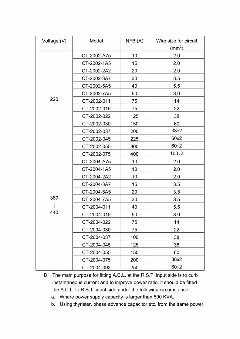
Voltage (V) Model NFB (A) Wire size for circuit
(mm2) CT-2002-A75 10 2.0 CT-2002-1A5 15 2.0 CT-2002-2A2 20 2.0 CT-2002-3A7 30 3.5 CT-2002-5A5 40 5.5 CT-2002-7A5 50 8.0 CT-2002-011 75 14 CT-2002-015 75 22 CT-2002-022 125 38 CT-2002-030 150 60 CT-2002-037 200 38×2 CT-2002-045 225 60×2 CT-2002-055 300 60×2
220
CT-2002-075 400 100×2 CT-2004-A75 10 2.0 CT-2004-1A5 10 2.0 CT-2004-2A2 10 2.0 CT-2004-3A7 15 3.5 CT-2004-5A5 20 3.5 CT-2004-7A5 30 3.5 CT-2004-011 40 5.5 CT-2004-015 50 8.0 CT-2004-022 75 14 CT-2004-030 75 22 CT-2004-037 100 38 CT-2004-045 125 38 CT-2004-055 150 60
380 |
440
CT-2004-075 200 38×2 CT-2004-093 250 60×2
D. The main purpose for fitting A.C.L. at the R.S.T. input side is to curb instantaneous current and to improve power ratio, it should be fitted the A.C.L. to R.S.T. input side under the following circumstance: a. Where power supply capacity is larger than 500 KVA. b. Using thyrister, phase advance capacitor etc. from the same power

supply. A.C.L. Specifications table:
Voltage (V) Model Current (Ar.m.s) Induction Value CT-2002-A75 6A 1.8mH CT-2002-1A5 10A 1.1mH CT-2002-2A2 15A 0.71mH CT-2002-3A7 20A 0.53mH CT-2002-5A5 30A 0.35mH CT-2002-7A5 40A 0.26mH CT-2002-011 60A 0.18mH CT-2002-015 80A 0.13mH CT-2002-022 120A 0.09mH CT-2002-030 150A 70uH CT-2002-037 200A 50uH CT-2002-045 250A 44uH CT-2002-055 300A 35uH
220
CT-2002-075 400A 27uH CT-2004-A75 5A 4.2mH CT-2004-1A5 5A 4.2mH CT-2004-2A2 7.5A 3.6mH CT-2004-3A7 10A 2.2mH CT-2004-5A5 15A 1.42mH CT-2004-7A5 20A 1.0mH CT-2004-011 30A 0.7mH CT-2004-015 40A 0.53mH CT-2004-022 60A 0.36mH CT-2004-030 80A 0.26mH CT-2004-037 100A 0.21mH CT-2004-045 120A 0.18mH CT-2004-055 150A 0.14mH CT-2004-075 200A 0.11mH
380 |
440
CT-2004-093 250A 0.10mH Notes: The A.C.L. for 220V and 380V/440V have different induction values, please do not mix up.

E. Standard External Connection Diagram
CPU
Operationalpanel
IM
BrakingControl
special request
DBRTH
P NPRDBR
U
V
W
VC
ACLMCB R
S
T
220V/50Hz200-230V/
60Hz400V/50Hz380-440V/
60Hz
PowerSupply
IN2
CC
VC
IN3
Ext. Operation controller5K 0-10V
4-20mA
FR
RR
1(AC2)
2(DC2)
3(3DF)
4(JOG/5DF)
Forward operation
TwistedShield wires
VOUT
CC
%tachometer(DC 10V MAX)
C1 No.1Multifunctional
relay outputterminal
3-phase
ConvertorAdaptor
Voltage detectCurrent detect
Interface
PowerControl
E
CC
IN1
CC
5(2DF)
6(MBS/RST)
COM
Reverse operation
Common terminal
Common terminal
Common terminal
Common terminal
Common terminal
Common terminal
Ext. Operation controller5K 0-10V
External Signal
NO1
NC1
C2
NO2
NC2
No.2Multifunctional
relay outputterminal
*
* While external is required for DBR,disconnect internal DBR first.

F. Control circuit
C1 NO1 NC1 NO2 NC2C2
No.1Multifunctional
relay outputterminal
No.2Multifunctional
relay outputterminal
Vout IN1 IN2 IN3 VC CC
1/2W5K ohm
1/2W5K ohm
0-10VDC
VoltageOutput
4-20mACurrent
Set
Main Voltage Set
AccessoryVoltage
Set
COM 1 2 3 4 5 6 COMRR FR
AC2 DC2 3DF JOG 2DF RST
��������
��������
��������
����������
����������
����������
����������
����������
Multi-functional
inputterminal
Multi-functional
inputterminal
Multi-functional
inputterminal
Reverseoperation
Forwardoperation

G. Terminal Specifications R.S.T AC power input
terminal 3∮AC power 200V/50Hz, 200-230/V/60Hz, 400V/50Hz, 400-460V/60Hz
U.V.W Inverter output terminal
3-phase induction motor
E Ground terminal Ground terminal of inverter chassis
Main Circuit
P.PR Brake resistor connecting terminal
Connected proper brake resistor according to rated ampere
VC Power speed output setting
DC 10V
IN1 Current speed input setting
DC 4-20mA, CD01=2
IN2 Voltage speed input setting
DC 0-10V/5KΩVR, CD01=1
IN3 Voltage speed input setting
CD 0-10V/5KΩVR, CD01=3
VOUT Operation (Frequency/Current) output indication
With “+”-VOUT and “-“-CC shorted input 0-10V DC, Frequency/Current set by CD54
Control Terminal
(1)
CC Common input control terminal
Ground terminal for speed setting
COM Sequence control common terminal
Ground terminal for sequence control
FR Forward operation input terminal
Forward operation by FR-COM shorted
RR Reverse operation input terminal
Reverse operation by RR-COM shorted
1 2nd acceleration input terminal (AC2)
Select 2nd acceleration time mode by shorting 1-COM, set CD10
2 2nd deceleration input terminal (DC2)
Select 2nd deceleration time mode by shorting 2-COM, set CD11
3 3rd speed input terminal (3DF)
Select 3rd operation speed by shorting 3-COM, frequency is set by CD13
4 Jogging operation or 5th speed (JOG/5DF)
Shorting 4-COM, JOG/5DF is set by CD59
Control Terminal
(2)
5 2nd speed input terminal (2DF)
Select 2nd operation speed by shorting 5-COM, frequency is by CD12

6 Free-run operation or alarm reset (MBS/RST)
Shorting 6-COM, MBS/RST is set by CD59
C1,NC1,NO1,C2,NC2,NO2
Control output terminal
����������
NO
NC
C
Multifunctional relay output terminal Connector capacity AC 220V, 0.1A While normal C-X closed and NC-X Closed While operating C-X open and NO-X closed Functions of C1, NC1, NO1 are set by CD47 Functions of C2, NC2, NO2 are set by CD48
5. Operational Test A. Check before test Please check the following:
(1) Is wiring correct? Check especially the input and output terminals. (2) Is there a short-circuit or ground connection on external wiring? (3) Make sure there is no loosening of screws. (4) Check external sequence control circuit. (5) Check voltage of power supply.
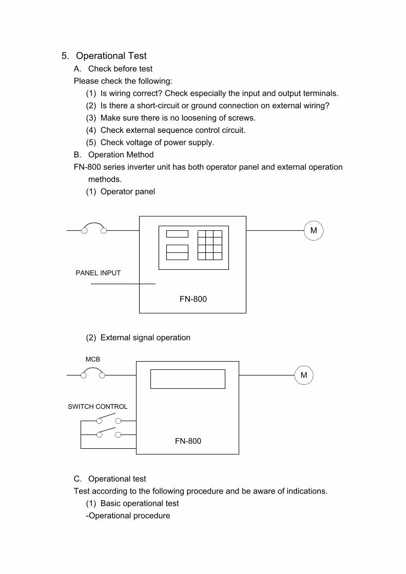
B. Operation Method FN-800 series inverter unit has both operator panel and external operation
methods. (1) Operator panel
FN-800
M
PANEL INPUT
(2) External signal operation
FN-800
M
SWITCH CONTROL
MCB
C. Operational test Test according to the following procedure and be aware of indications.
(1) Basic operational test -Operational procedure

I. Connect power supply II. Monitor glittering indicates frequency III. Press either FWD or REV key, motor starts running. It will stop
accelerating after reaching set frequency IV. After pressing STOP key, motor stops and indicating frequency
steps down. The set frequency starts glittering after the motor stops.
V. Repeat procedures III and IV to test forward and reverse operations.
-Operation monitor display I. Stop display, with reciprocal glittering indicated Hz LED and
factory setting 10.00 Hz. II. Hz display, with FWD(or REV) LED lighted up steadily,
indication goes up according to frequency until reaching value 10.00 Hz
III. Indication goes down according to operation frequency, and returns to situation ” I ” after stop
(2) Frequency change test - Operational procedure
I. Exercise the above operation test procedures I, II, III II. Directly press panel number key to input value III. Use SET key to change frequency value
※ Directly use step keys at procedure II to change, or use function keys (PROG, READ, SET) to program
IV. Repeat procedures II, III to increase or decrease frequency -Operation monitor display
I. The same as the above basic test of I, II II. Monitor display indicates the input value while motor is running
as the original setting III. Monitor display indicates the current new setting value
Note: 1. Is motor operation direction correct? (Changing any two of
U.V.W output terminals to change motor operation direction) 2. Is there any noise or vibration on motor? 3. Is it run smoothly during acceleration and deceleration? 4. Is there any power failure?

6. Adjust and Function Specification
7-segementmonitor
1.Displays frequencyCd02=0
Displays current Cd02=1Displays RPM NO2=2
Displays various readingssee Cd02
2. After indicates alarm,ignore Cd02, directly
displaysfailure status
READYDisplays that the panel isready to accept key input
Monitor modedisplay
Displays monitor status
Ten-key pad
987
654
321
.0
Cutes Corporation
1
1
STOPREV
SETREAD
FWD
PROG
。READY。HZ。A
。ALARM
Operation monitordisplay
Displays forward/reverse/stop status
Operation instructionkeys
Control from keyboardExternal control operation, stop
mode by set Cd04=1
STOP key
1. Stops inverter operation2. Resets function
3. Resets alarm indication
Step keys
1. To change frequency2. Select function items
Function setting keys
These three keys offer selectingread or setting value of function
Operator panel partsnames and functions
Data input key
§Code No. 00 Set frequency (settable range 0-240 HZ) There are 5 methods to change set frequency, items A-C are methods of panel key operation, items D-E are methods of external terminal input.
A. Directly use number keys to input data B. Use PROG key to input data

C. Use step keys(▲,▼) for setting D. Set external voltage E. Set external current
Note: 1. Set value should be in accordance with V/F slope (CD05) and upper
limit frequency (Cd17). Set function key
PROG
READ
SET
SET
0
0
00 0
0
00
0
0
0
0
0
0
C
C
C
d
d
d
3
3
3
3
Set step key (▲,▼)
Press [Arrow up] key (▲) to increase set frequency. Press [Arrow down] key (▼) to decrease set frequency.
§Code No.01 Setting procedure of frequency (Selective range 0-7) The function cannot be modified during revolution. Setting procedure of frequency is to select either panel key or external analog signal . Cd01=0 Set frequency on operation panel, as the above items A-C. Cd01=1 Set frequency by terminal In2 DC 0-10V/5KΩVR Cd01=2 Set frequency by terminal In1 DC 4-20mA Set number key Ex.: Set frequency to 20Hz
2
0
SET
2
2
2 0 0 0
0
Ex. Instant change to 20Hz
*Note:

1. Displays frequency only in frequency status. §Code No.02 Select monitor display (Selective range 0-6) The monitor is consisted of four 7-setment LEDs, displays frequency, current and various data by digital number and character. Cd02=0 Display the frequency, LED HZ active Cd02=1 Display the current, LED A active Cd02=2 Display RPM, LED HA, A de-active Cd02=3 Display DC bus Cd02=4 Display rms of U.V.W AC output Cd02=5 Display external control terminal status Cd02=6 Display MCK §Code No.03 Torque mode (Selective range 0,1) The function cannot be modified during revolution. Cd03=0 Automatic torque compensation de-active, set compensation by Cd07. Cd03=1 Automatic torque compensation active, the largest compensation is 2 times of the setting Cd07. §Code No.04 Operation command mode (Selective range 0,1) The function cannot be modified during revolution. Cd04=0 Operation on operation panel Cd04=1 Operation by external terminal, including FR, RR, common terminal (1, 2, 3, 4, 5, 6) §Code No.05 Set V/F pattern (Selective range 1-11) The function cannot be modified during revolution. There are 11 patterns of V/F slope, as follow:

V
V
V
V
V
V
V
V
V
V
F F
F
F
F
F
F F
F F
1 2 3
6 7 8
4
109
5
50HZ 60HZ 50HZ 100HZ 60HZ 120HZ
50HZ 150HZ 60HZ 180HZ 50HZ 200HZ 60HZ 240HZ
87HZ 174HZ 103HZ 206HZ
When Cd05=11, V/F slope is determined by Cd57, Cd58. Note: Select Cd05=11 if set frequency exceeds 240 Hz. §Code No.06 Motor current rate (Settable range 25-100) Set motor overload protective current, in order to avoid motor failure because of overload. Set value=100, please calculate the following formula: Set Value = Motor rated current / Inverter rated current ×100 Ex. Use inverter with 3.7KW(5HP) to drive motor with 2.2KW(3HP) Inverter rated current = 17.4A Motor rated current = 8A Set Value = 8 / 17.4 ×100 = 46% §Code No.07 Torque compensation Vb (Settable range 0-150) The function cannot be modified during revolution. This function is to raise output voltage to increase torque of motor. It can also be used to increase load slope of low voltage produced by long wiring between inverter and motor, as well as fluid, fan and pump.

100%
50%
15%
0%FS
Output Frequency (HZ)
Out
put V
olta
geVB
§Code No.08, 09, 10, 11 Acceleration / deceleration time (Settable range 0.1-9999) The time needed for set frequency from 0Hz to 50Hz. There are 2 selections for each of acceleration time and deceleration time. To set acceleration/deceleration time Set Value (T) = (50 - 0) / △F ×T1 T1: time needed for accelerate / decelerate △F: frequency changed Ex.: Frequency from 50Hz down to 30Hz, needed time 1 sec. Then: Set Value (T) = 50 / 50 - 30 ×1 = 2.5 Cd08 = Acceleration time Cd09 = Deceleration time Cd10 = 2nd Acceleration time Cd11 = 2nd Deceleration time Note: The 2nd acceleration / deceleration time only available on external operation mode (e.g. Cd03=1). §Code No.12, 13, 14 Speed setting (Settable range 0.5-240) This function has 4 kinds of speed setting The 2nd , 3rd, 4th speeds are set from external terminal FR (or RR) which accommodate terminal 3, 5, the setting value cannot exceed the allowed range. Cd12 = 2nd speed setting Cd13 = 3rd speed setting Cd14 = 4th speed setting Note: When apply to multi-speed setting, use external control (e.g. Cd03=1) to start and use panel to pre-input to set frequency.

§Code No.15 Jogging frequency (Settable range 0.5-30) To control jogging, use external terminal 4-FR or 4-RR with COM shorted. Set running direction
FR or RR
Runningmode:
Jogging
Forward(Reverse)
2
Note: Jogging operation is valid only when operation command selects the external operation signal mode (e.g. Cd03=1) and Cd59=0 or 1. Jogging operation procedures:
1. First put in 4, and then FR (or RR). 2. Put in 4 and FR (or RR) simultaneously.
Be sure always to put in 4 before FR (or RR). §Code No.16 Start frequency (Settable range 0.5-30) Set motor start frequency Settable range of frequency is 0.5Hz to 30Hz, accuracy is 0.01Hz.
Time
StartFrequency
Frequency
Note: The most appropriate range for start frequency is 0.5Hz to 10Hz. § Code No.17 Upper limiter of frequency (Selective range 10-240) This limiter is used to operate within upper limit frequency of motor Avoid input errors caused by the panel keys and result in mechanical

damage. Note: If set frequency exceeds 240Hz, set Cd05=11. §Code No.18 Lower limiter of frequency (Settable range 0.5-100) This limiter is used to operate within lower limit frequency of motor
FHOutputFrequency
UpperLimiter
LowerLimiter
Set Frequency Operation
§Code No.19 Acceleration / deceleration time of jogging (Setting range 0.10-30.00) Time needed for set frequency from 0Hz to 50Hz. Set Value (T) = (50 - 0) / △F ×T1 T1: Time needed for acceleration/deceleration △F: Frequency changed §Code No.20, 21 Jump frequency (Settable range 0-240) This function is to avoid mechanical resonance frequency Frequency operation automatically jumps to point +/- jump width (set by Cd22) This function is only available on constant speed operation, not influence during acceleration/deceleration, it is settable at 2 points.
Cd21Cd22
Cd20 Cd22
Time
OutputFrequency
§Code No.22 Jump frequency width (Settable range 0-6) This function must accommodate Cd20 and Cd21

§Code No.23 Braking mode (Settable range 0-3) This function must accommodate Cd24, Cd25, Cd26. Cd23=0 No DC braking Cd23=1 Stop mode Cd23=2 Start mode Cd23=3 Stop and start mode §Code No.24 DC braking frequency (Settable range 1-10) This function must accommodate Cd23, Cd25, Cd26. Set frequency of DC brake starts at the time of inverter deceleration stops, the DC brake is active when operates below the starting frequency. §Code No.25 DC braking voltage (Settable range 1-15) This function must accommodate Cd23, CD24, Cd26. DC braking torque setting When DC brake is active, monitor displays “dCbr” Cd25=1-15, the higher value the higher output brake torque Note: When DC brake voltage is high, be aware of over current. §Code No.26 DC braking time (Settable range 1-60) Adjust DC braking time
Braking Time
BrakingFrequency
Time
Time
BrakingRate
StartFrequencyO
utpu
t Fre
quen
cyBr
akin
g Vo
ltage
Note: 1. DC braking time too long or too many times is possible to cause
motor damage because of overheat.
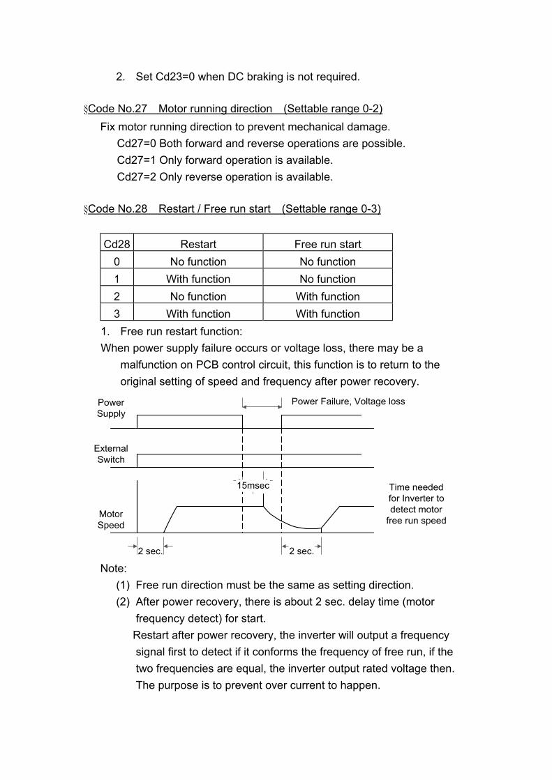
2. Set Cd23=0 when DC braking is not required. §Code No.27 Motor running direction (Settable range 0-2) Fix motor running direction to prevent mechanical damage. Cd27=0 Both forward and reverse operations are possible. Cd27=1 Only forward operation is available. Cd27=2 Only reverse operation is available. §Code No.28 Restart / Free run start (Settable range 0-3)
Cd28 Restart Free run start 0 No function No function 1 With function No function 2 No function With function 3 With function With function
1. Free run restart function: When power supply failure occurs or voltage loss, there may be a
malfunction on PCB control circuit, this function is to return to the original setting of speed and frequency after power recovery.
PowerSupply
ExternalSwitch
MotorSpeed
Power Failure, Voltage loss
2 sec.2 sec.
15msec Time neededfor Inverter todetect motor
free run speed
Note: (1) Free run direction must be the same as setting direction. (2) After power recovery, there is about 2 sec. delay time (motor
frequency detect) for start. Restart after power recovery, the inverter will output a frequency
signal first to detect if it conforms the frequency of free run, if the two frequencies are equal, the inverter output rated voltage then. The purpose is to prevent over current to happen.
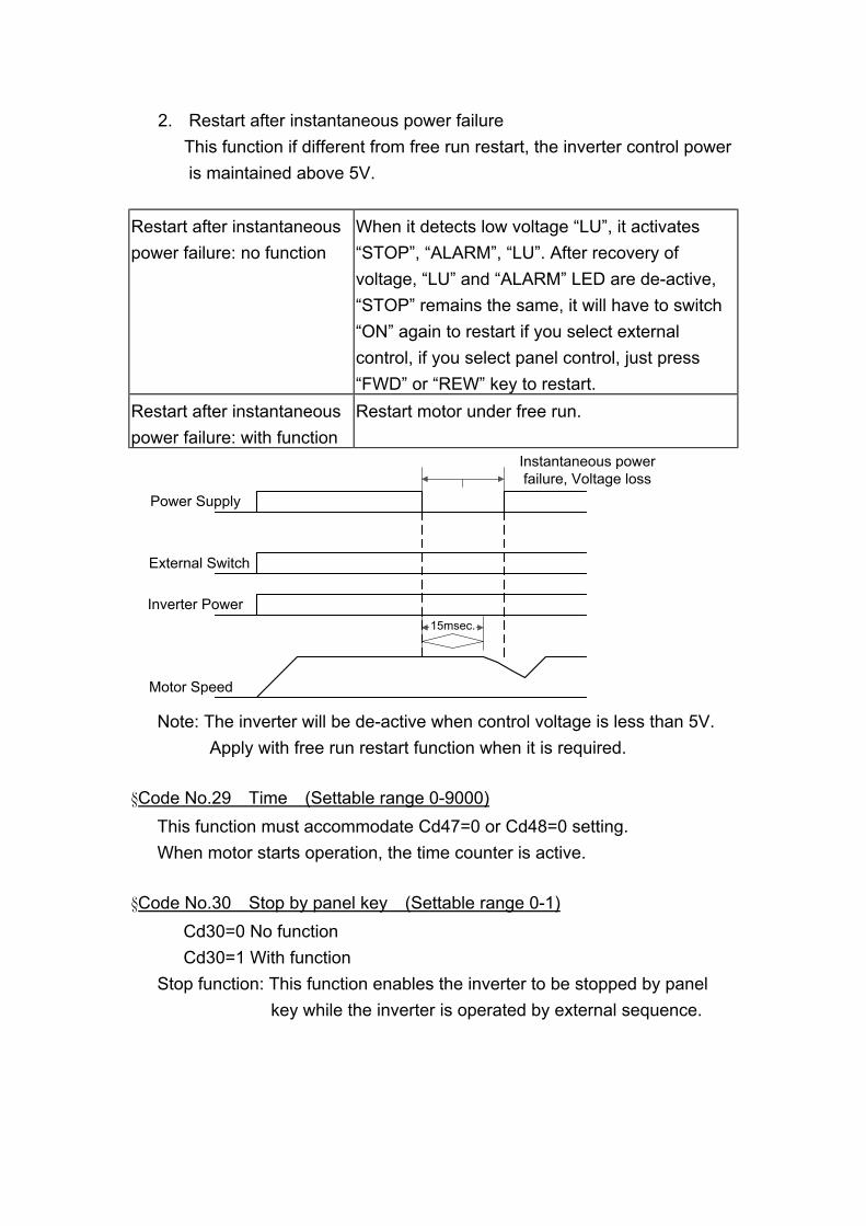
2. Restart after instantaneous power failure This function if different from free run restart, the inverter control power
is maintained above 5V. Restart after instantaneous power failure: no function
When it detects low voltage “LU”, it activates “STOP”, “ALARM”, “LU”. After recovery of voltage, “LU” and “ALARM” LED are de-active, “STOP” remains the same, it will have to switch “ON” again to restart if you select external control, if you select panel control, just press “FWD” or “REW” key to restart.
Restart after instantaneous power failure: with function
Restart motor under free run.
15msec.
Power Supply
External Switch
Inverter Power
Motor Speed
Instantaneous powerfailure, Voltage loss
Note: The inverter will be de-active when control voltage is less than 5V. Apply with free run restart function when it is required. §Code No.29 Time (Settable range 0-9000) This function must accommodate Cd47=0 or Cd48=0 setting. When motor starts operation, the time counter is active. §Code No.30 Stop by panel key (Settable range 0-1) Cd30=0 No function Cd30=1 With function Stop function: This function enables the inverter to be stopped by panel key while the inverter is operated by external sequence.

§Code No.31 Initial factory setting (Settable range 0,1) The function cannot be modified during revolution. Set data to original factory setting. Cd31=0 No change Cd31=1 Initial factory setting, refer to function code table. Note: After this function is active, content value returns to “0”, readable value is always “0”. §Code No.32, 33, 34, 35 Failure record Record cause of failure, in order to solve failure. Note:
1. Cannot record failure Err, Ero, Erc. 2. Only memorize 4 records. 3. Cannot record inverter stopped by low voltage. 4. Read only Code 32, 33, 34, 35 or delete all (Code 36), cannot put
in failure record by operator. §Code No.36 Failure record clear (Settable range 0, 1) Clear the failure record content of Code 32, 33, 34, 35. Cd36=0 No change Cd36=1 All of the contents of data will be “nOnE”. Note: After this function is active, content value automatically returns to “0”, thus readable value is always “0”. §Code No.37 Frequency gain setting (Settable range 20-200) Select ratio of frequency gain Gain setting for external signals is available using this function. Output Frequency = Set Value ×Frequency Gain Ex. Under the mode of external voltage (0-10V) frequency setting, frequency gain = 100%, set voltage to 2V, Output Frequency = (2V/10V) ×120Hz ×100% = 24Hz If change frequency gain to 150%, then Output Frequency = (2V/10V) ×120Hz ×150% = 36Hz

200%
100%
20%
200 100
2010V20mA
0V4mAAnalog Setting Signal
Note: If the maximum frequency exceeds more than 120Hz, gain setting of larger than 100% is ignored and fixed at 100% and input data of Code 37 will not be changed. §Code No.38 Analog output calibration (Settable range 90-110) Set the ratio of frequency graduation calibration then Cd38=99 99% of initial factory Cd38=101 101% of initial factory Set Cd54 to select analog output §Code No.39 Frequency command bias (Settable range 0-250) External analog frequency command bias setting
Frequency Output %
Frequency CommandSettable Range
10V0V
§Code No.40, 41, 42, 43 Multi-speed setting (Settable range 0.5-240) This function has 8 kinds of speed operation Use external terminal FR (or RR) accommodate 3, 4, 5 to select different speeds. Refer to the following table: Cd40=0 5th speed setting Cd40=1 6th speed setting Cd40=2 7th speed setting

Cd40=3 8th speed setting Note:
Apply to multi-speed setting, external control is required for operation control mode (e.g. Cd04=1), and it is also required to set Cd59 for activating common terminal 4.
External terminal Name
Selective speed
2 3 4 5 6 7 8 Terminal 5 ○ ○ ○ ○ Terminal 3 ○ ○ ○ ○ Terminal 4 ○ ○ ○ ○
○: stands for external terminal to put in. §Code No.44 Stop mode (Settable range 0-2) Cd44=0 Deceleration stop Cd44=1 Free run stop Cd44=2 Free run stop, but restart after the deceleration time is reached, Deceleration time is set by Cd11. §Code No.45 Frequency detect level (Settable range 0.5-240) This function is only available when RELAY output terminal Cd47=6 or Cd48=6, and Cd45 is assigned.
HZ OUTPUT
CD45
FA-FC
OPENCLOSE TIME
TIME
§Code No.46 Speed multiplier (Settable range 0.01-500) The function shows revolution speed multiplied by a scaling factor on the 7-segment display.

1. Hz and A LED de-active. 2. RPM = Frequency ×Speed multiplier. 3. If the value overflow, it will show “9999”.
§Code No.47 Relay 1 output select (Settable range 0-6) The function sets the mode of relay to activate.
Cd47 Specification Remark 0 Time counter Time reached to the content of Cd29 1 Fault 2 Stop 3 Acceleration 4 Speed reached 5 Deceleration 6 Speed pass over Revolution frequency >content of Cd45
§Code No.48 Relay 2 output select (Settable range 0-6) The function sets the mode of relay to activate.
Cd48 Specification Remark 0 Time counter Time reached to the content of Cd29 1 Fault 2 Stop 3 Acceleration 4 Speed reached 5 Deceleration 6 Speed pass over Revolution frequency >content of Cd45
§Code No.49 Function to lock data (Settable range 0, 1) To lock data, prevent errors by none operator. Cd49=0 Data change capable Cd49=1 Data change not capable §Code No.50 Software version (Read only) This function is to record software version, read only.
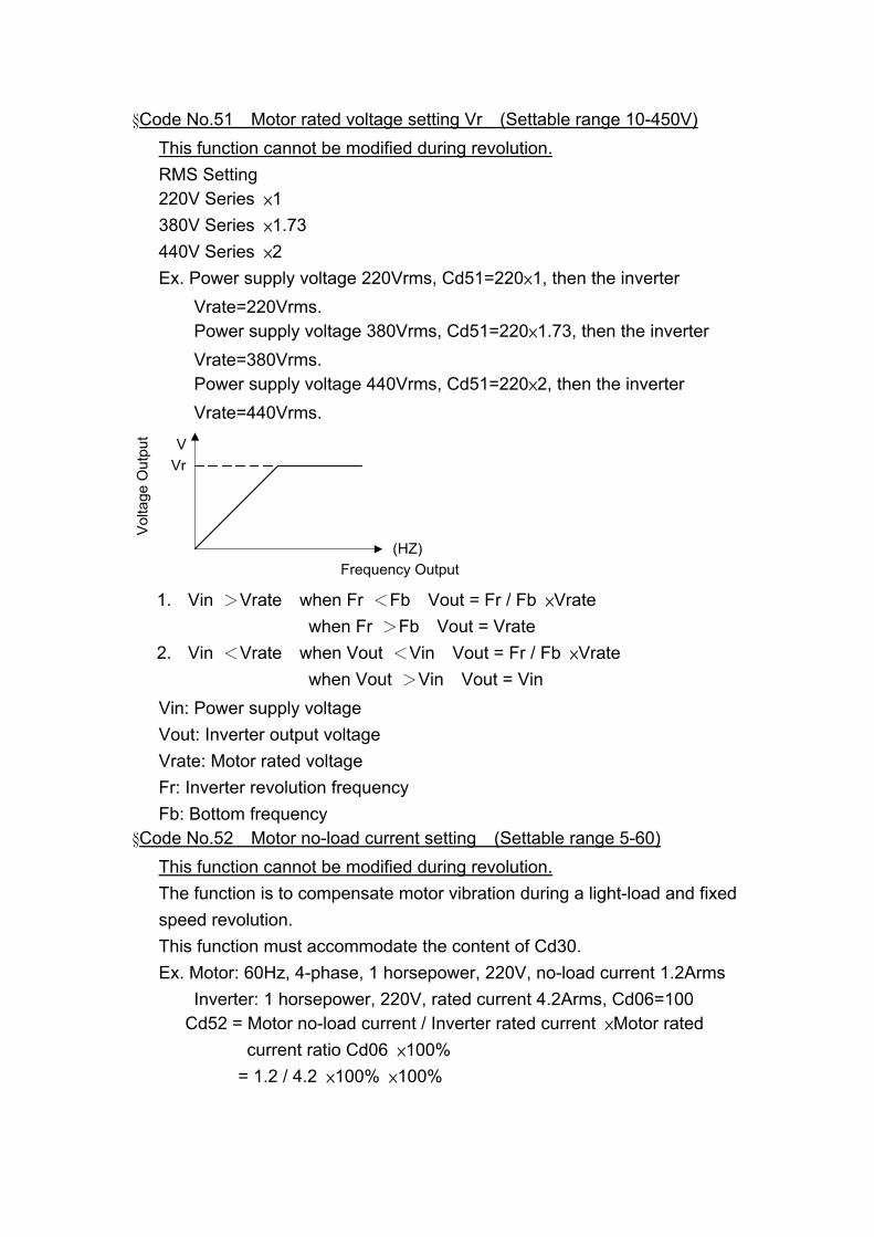
§Code No.51 Motor rated voltage setting Vr (Settable range 10-450V) This function cannot be modified during revolution. RMS Setting 220V Series ×1 380V Series ×1.73 440V Series ×2 Ex. Power supply voltage 220Vrms, Cd51=220×1, then the inverter Vrate=220Vrms. Power supply voltage 380Vrms, Cd51=220×1.73, then the inverter Vrate=380Vrms. Power supply voltage 440Vrms, Cd51=220×2, then the inverter Vrate=440Vrms.
Volta
ge O
utpu
t
Frequency Output(HZ)
VrV
1. Vin >Vrate when Fr <Fb Vout = Fr / Fb ×Vrate
when Fr >Fb Vout = Vrate 2. Vin <Vrate when Vout <Vin Vout = Fr / Fb ×Vrate
when Vout >Vin Vout = Vin Vin: Power supply voltage Vout: Inverter output voltage Vrate: Motor rated voltage Fr: Inverter revolution frequency Fb: Bottom frequency §Code No.52 Motor no-load current setting (Settable range 5-60) This function cannot be modified during revolution. The function is to compensate motor vibration during a light-load and fixed speed revolution. This function must accommodate the content of Cd30. Ex. Motor: 60Hz, 4-phase, 1 horsepower, 220V, no-load current 1.2Arms Inverter: 1 horsepower, 220V, rated current 4.2Arms, Cd06=100 Cd52 = Motor no-load current / Inverter rated current ×Motor rated current ratio Cd06 ×100% = 1.2 / 4.2 ×100% ×100%

= 28.5% §Code No.53 Motor slip differential compensation (Settable range 0-100) This function is to compensate speed variation produced by load variation. This function must accommodate the content of Cd52. Setting value 0-100 in relative slip differential 0.0-10.0% Ex. 60HZ, 4-phase 1700 rpm Synchronous speed = 1800 rpm Full-load speed = 1700 rpm Slip differential speed = 1800-1700=100 rpm Slip differential % = Slip differential speed / Synchronous speed × 100% = 100 / 1800 ×100% = 5.5%
Slip differential compensation
Loadvariation
Motorspeed
Motorspeed
Outputfrequency
Time
Without slipdifferential
compensation
With slipdifferential
compensation
With slipdifferential
compensation

§Code No.56 Overcurrent stall preventive mode (Settable range 10-200%) This function is to prevent when motor current exceeds stall current from stall. There are 2 kinds of acceleration time slopes when motor acceleration current exceeding stall current occurs: Instantaneous load increase during steady operation and current exceeding overcurrent stall, revolution frequency will drop till current dropped to within stall current level.
Freq
uenc
y
Freq
uenc
y
TimeTime
Time TimeDuringacceleration
Druing speedreached
Stallpreventive
mode
Stallpreventive
mode
Inve
rter c
urre
nt
Inve
rter c
urre
ntStallcurrentlevel
Stallcurrentlevel
NormalStatus
§Code No.57 Maximum frequency setting FH (Settable range 10-240) This function cannot be modified during revolution. When Cd05=11, the maximum frequency V/F slope FH Settable range 10Hz-240Hz Please refer to function code table. §Code No.58 Bottom frequency setting Fb (Settable range 10-240) This function cannot be modified during revolution. When Cd05=11, the bottom frequency V/F slope Fb Settable range 10Hz-240Hz (Fb ≦FH) Please refer to function code table.

§Code No.59 Select external terminal 4 / 6 (Settable range 0-3) This function is to select setting common terminal 4 and 6. CD59 Common input terminal setting
0 External terminal 4=JOG External terminal 6=MBS 1 External terminal 4=JOG External terminal 6=RST 2 External terminal 4=5DF External terminal 6=MBS 3 External terminal 4=5DF External terminal 6=RST
Terminal specification: JOG: Jogging operation 5DF: Multi-speed MBS: Free run stop, operates both panel key and external signal. RST: Reset, operates both panel key and external signal. §Code No.60 V / F frequency FC (Settable range 0.5-240) This function cannot be modified during revolution. To set V/F slope frequency FC when Cd05=11. Settable range 10Hz-240Hz (FC ≦Fb)
Out
put V
olta
ge
Output Frequency(HZ)
15%
0%
150
0
FC Fb FH
Cd7 VB
Cd60 Cd58 Cd57
§Code No.61 PWN frequency This function is to set PWN frequency
Cd61 PWM Frequency 1 4 KHZ 2 6 KHZ 3 8 KHZ 4 10 KHZ 5 12 KHZ 6 14 KHZ
Note: The maximum PWM frequency setting value is 8 KHZ for inverter above 20HP (including 20HP).

7. Description of alarm display indications Error indication Description of fault operation Item for inspection Processing
Err Operation error Was the unit operated as
indicated in the manual
Use the correct procedure
ErO Operation error of internal
ROM, RAM
Switch off the power and then
apply again
Replace the unit
ErC Error of internal CPU Is there a large amount of
external noise
Check the contact absorber. Install
a noise filter
OCPA Overcurrent (180% rated
current)
Was there rapid acceleration Lengthen the acceleration time
OCPd Overcurrent (180% rated
current)
Was there rapid deceleration Lengthen the deceleration time
OCPn Overcurrent (180% rated
current)
Was there any variation in the
load
Lengthen the time for the load
variations
OC Overcurrent (200% rated
current)
Was there rapid acceleration /
deceleration and variation in the
load
Lengthen the acceleration and
deceleration time and reduce the
load
OCS Output short circuit or ground
detected
Is there a short circuit for the
output or grounding for the
motor
Perform a megger check for the
motor
OU DC link overvoltage Was there fast deceleration, or
fast voltage
Lengthen the deceleration time.
Investigate the use of the optional
DBR
LU Insufficient voltage detected
due to power failure or
instantaneous power loss.
Is there a low voltage at power,
or internal inverter wiring error
Improve the voltage condition and
confirm inverter model
OH Overheating of the cooling
fan detected
1. Cooling fan stops
2. Ambient temperature too
hot
3. Motor being overload
1. Exchange the cooling fan
2. Lower the ambient
temperature
3. Check the load conditions
OL Overload detected for more
than one minute
Is the motor being overloaded Increase the capacity of the
inverter and motor
bUOH DBR overheat detected Is the braking ratio appropriate Reduce GD2 of load or lengthen
deceleration time
Fb Blown fuse Is the fuse blown Change a fuse
PLU Power voltage too low Is power voltage too low Improve power supply condition

8. Troubleshooting Description of trouble Possible cause Solution
1. Wiring error Refer to the wiring diagram
1. Check the power input wiring
2. Is there a voltage for U.V.W output
2. Wrong settings at
operator panel
The function code No.04 is as follows
0: Panel key operation
1: External signals
3. Inverter displays fault
indication
Refer to “Protect Function”
4. Motor cannot start due
to overload
Exchange a higher capacity one
5. Motor breaks down Repair motor
The motor does not
run at all
6. Inverter breaks down Please contact us
1. Motor wiring error Refer to the wiring diagram
2. Overload Reduce the load or increase inverter
capacity
3. Is V/F slope
appropriate
Check Code 05 V/F slope is appropriate
with motor specification
4. Is start torque
appropriate
Adjust Code 07 torque boost to over come
steady friction but not over current trip.
5. Is the acceleration
time too short when
compared to load GD2
Lengthen acceleration time by apply Code
08 and Code 10 or increase inverter
capacity
“OCPA” is indicated
as soon as the motor
is started.
(Overcurrent protect
operation during
acceleration.)
6. The inverter is starting
during motor free-run
Refers to Code 28, change the value from
0 to 1
“OCPd” is indicated
as the motor is
decelerating.
(Overcurrent protect
operation during
deceleration).
1. Deceleration time too
short, unable to be
loaded
Apply Code 09 and Code 11 to lengthen
deceleration time or increase inverter
capacity
1. Short circuit on U.V.W
or grounding for motor
Exclude short circuit or grounding
2. Instantaneously
mechanical load on
motor
Reduce load or increase inverter capacity
“OC” or “OCS” is
indicated during
operation.
(Overcurrent)
3. Motor breaks down Repair motor

4. Inverter breaks down Please contact us
1. Is power voltage with
the specification
Improve power voltage condition
2. Braking resistor not
applied
Apply braking resistor, increase braking
ratio
“OU” is displayed
during inverter
operation
3. Deceleration time too
short, unable to be
loaded
Apply Code 09 and Code 11 to lengthen
deceleration time
1. Is power voltage with
the specification
Improve power voltage condition
2. Instantaneous power
voltage failure
Check the capacity of the power facilities
“LU” is displayed
during inverter
operation
3. Power dropped and
the protector function
has operated
Check the capacity of the power facilities
1. Overload Reduce load or increase inverter capacity “OL” is displayed
during inverter
operation
2. Is inverter overcurrent
limiter appropriate
Apply Code 06 to re-set motor rated
current
1. Check if the cooling
fan is still working
Change cooling fan and clean dirt “OH” is displayed
during inverter
operation 2. Is ambient
temperature too hot
Improve ambient temperature condition
1. Power failure Check the capacity of the power facilities No any indication, the
output frequency
displayed “0”
2. Is there loosen part on
external control
terminal
Check external control terminal

9. Maintenance and Inspection Maintenance and inspection must be taken under power off. Cautions on maintenance and inspection:
(1) Capacitor is charged at high voltage for a while after turning off the power. (Accordingly, start the inspection work at least 5 minutes after turning off the power)
(2) Do the work with operator. Inspection items:
(1) Please check the following items A. Motor runs as expected. B. Avoid installing on circumstances like acid, alkaloid. C. No trouble is recognized in the cooling system and irregular
vibration or noise. D. No parts is overheated or burned.
(2) Periodic inspection
Interval Inspection item Every 6 months 1. Terminal plates and mounting bolts.
2. Corrosion and breaks in the terminal clips for the wiring.
3. Condition for the connector fixing. Once a year 1. Use clean, dry air to remove dust buildup from
the guards, the stack and the cooling fan. 2. Check for parts burns or damage and make
any exchanges necessary.

10. Function Code Table Code No.
Function Detail of Data Initial factory setting
0 Set frequency 0-240Hz 10 1 Frequency setting
procedure 0: Operation panel Cd00 1: External IN2 (0-10V) 2: External IN1 (4-20mA)
0
2 Select monitor display data
0: Frequency (HZ) 1: Current (A) 2: r.p.m 3: DC Voltage 4: Output AC Voltage 5: External I/O status
0
3 Torque mode 0: Without auto boost 1: With auto boost
1
4 Operation command 0: Operation panel 1: External signal
0
5 V/F pattern 1-10 fixed Modes 11: Set by CD57, CD58
2
6 Motor rated current 25-100% 100 7 Torque boost 0-150 (0-15.0%) 20 8 1st acceleration time 0.1-9999 (S/50HZ) 5 9 1st deceleration time 0.1-9999 (S/50HZ) 5
10 2nd acceleration time 0.1-9999 (S/50HZ) 10 11 2nd deceleration time 0.1-9999 (S/50HZ) 10 12 No.2 frequency HZ 20 13 No.3 frequency HZ 30 14 No.4 frequency HZ 40 15 Jogging frequency 0.5HZ-30HZ 5 16 Start frequency 0.5HZ-30HZ 1 17 Upper limit frequency 10-400HZ 60 18 Lower limit frequency 0-100HZ 0 19 Jogging acceleration /
deceleration time 0.1-10 (S/50HZ) 1
20 Jump frequency 1 HZ 0 21 Jump frequency 2 HZ 0 22 Jump frequency width 0-6HZ 1 23 Braking mode 0: de-active 0

1: Active when stop 2: Active when start 3: Active both stop and start
24 DC braking frequency 1-10HZ 1 25 DC braking rate 0-15 5 26 DC braking time 1-60 Sec. 1 27 Operation direction
setting 0: Both forward and reverse 1: Forward only 2: Reverse only
0
28 Restart in instantaneous power failure / Free run start
0: Without / Without 1: With / Without 2: Without / With 3: With / With
0
29 Time 1-9000 (Sec.) 5 30 “Stop” function at
panel key under the operation of external sequence
0: Impossible 1: Possible
1
31 Initialize data 0: No change 1: Data at the time of shipment
0
32 Fault annunciation (The last)
nOnE
33 Fault annunciation (Before the last)
nOnE
34 Fault annunciation (The 2nd before the last)
nOnE
35 Fault annunciation (The 3rd before the last)
OCPA OCPN OCPD OCS OC OL OU PLU LU Fb Erc nonE nOnE
36 Memory clear for fault annunciation
1: Memory clear 0
37 Frequency gain setting 20-200% 100 38 Analog output calibrate 90-110% 100 39 Frequency command
bias 0-250 125
40 No.5 Frequency HZ 45 41 No.6 Frequency HZ 50

42 No.7 Frequency HZ 55 43 No.8 Frequency HZ 60 44 Stop mode 0: Decelerate stop
1: Free run stop 2: Free run stop after deceleration time is reached
0
45 Detect frequency level 0.5-240HZ 0.5 46 Speed multiplier 0.01-500 1 47 Relay 1 output select 0-6 1 48 Relay 2 output select 0-6 4 49 Lock data 0: Data change capable
1: Data change not capable 0
50 Software version Read only 1 51 Motor rated voltage 10-450
200V Series×1 380V Series×1.73 400V Series×2
220
52 Motor no-load current 5-60% 30 53 Motor slip differential
boost 0.0-10.0% 0
54 External analog output select
0: Display output frequency 1: Display output current
0
55 56 Current stall
preventive 10-200% 150
57 Max. frequency FH setting
10-240HZ (FH) 60
58 Motor rated frequency Fb
10-240HZ (Fb) FH ≧Fb
60
59 MBS / RST JOG / 5DF
0: Terminal 4=JOG, 6=MBS 1: Terminal 4=JOG, 6=RST 2: Terminal 4=5DF, 6=MBS 3: Terminal 4=5DF, 6=RST
0
60 V/F Frequency FC 0.5-240HZ 0.5 61 P.W.M. Frequency 1: 4KHZ 4: 10KHZ
2: 6KHZ 5: 12KHZ 3: 8KHZ : 14KHZ
3