Embed Size (px)
Citation preview
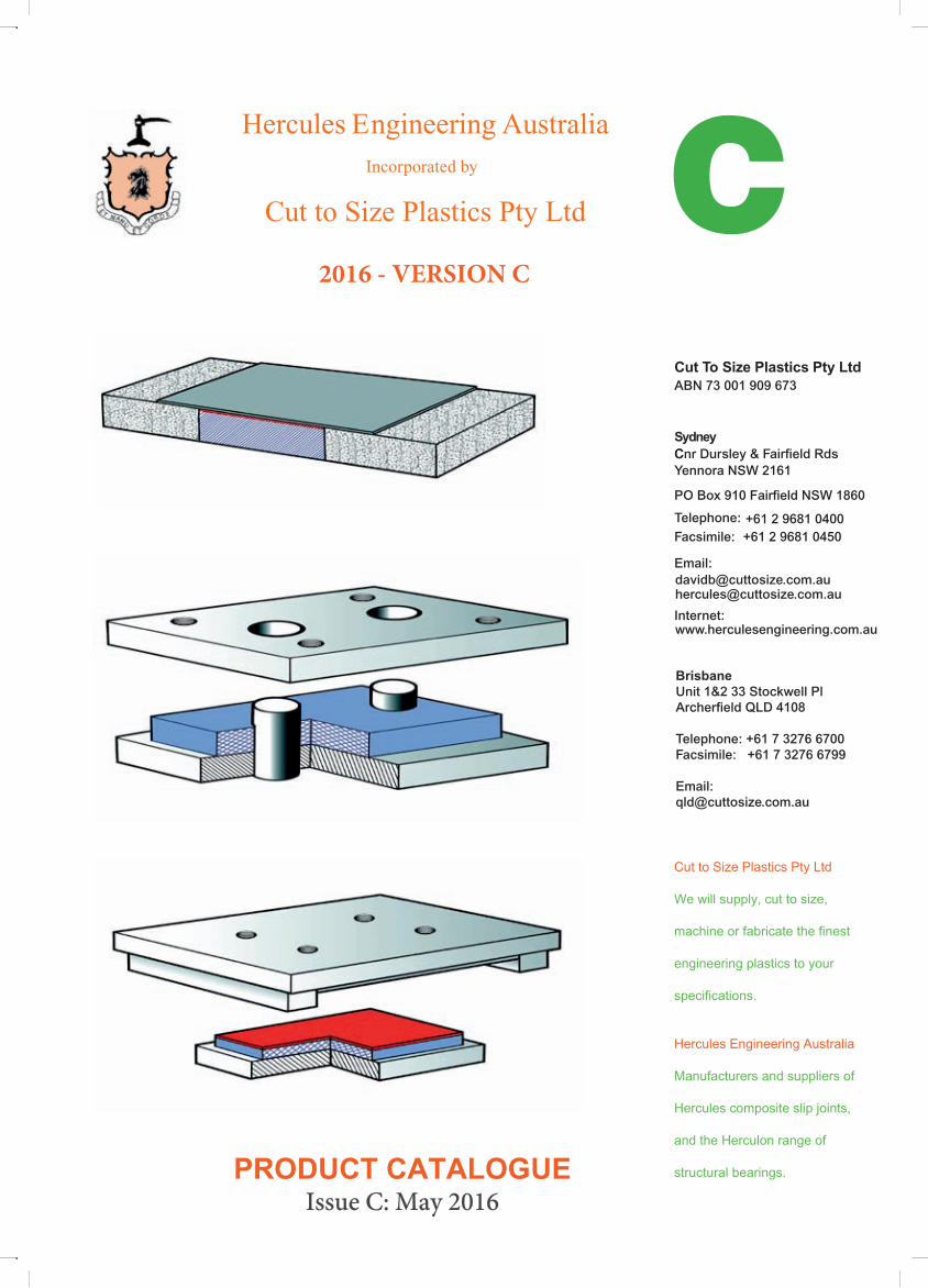
Cut to Size Plastics Pty Ltd incorporating
Hercules Engineering Australia
PRODUCT CATALOGUEIssue C: May 2016
ABN 73 001 909 673
24 Whiting Street
Artarmon NSW 2064
Sydney Australia
PO Box 559
Artarmon NSW 1570
Telephone: +61 2 9439 7066
Facsimile: +61 2 9439 2494
Email: [email protected]
Internet: www.cuttosize.com.au
Cut to Size Plastics Pty Ltd
We will supply, cut to size,
machine or fabricate the finest
engineering plastics to your
specifications.
Hercules Engineering Australia
Manufacturers and suppliers of
Hercules composite slip joints,
and the Herculon range of
structural bearings.
Hercules Engineering Australia
Cut to Size Plastics Pty Ltd
Incorporated by
Cut To Size Plastics Pty LtdABN 73 001 909 673
Cnr Dursley & Fairfield RdsYennora NSW 2161
PO Box 910 Fairfield NSW 1860
Telephone: +61 2 9681 0400Facsimile: +61 2 9681 0450
Email:
www.herculesengineering.com.au
CSydney
[email protected] @cuttosize.com.auhercules
Internet:
BrisbaneUnit 1&2 33 Stockwell PlArcherfield QLD 4108
Telephone: +61 7 3276 6700Facsimile: +61 7 3276 6799
Email:[email protected]
2016 - VERSION C
© Hercules Engineering Australia March 2005
This publication is copyright. Apart from any use as permitted under the Copyright Act 1968 (as amended), no partmay be reproduced, stored in a retrieval system or transmitted in any form or by any means, electronic or mechanical, including photocopying without prior written permission of Hercules Engineering Australia.
Requests and inquiries concerning reproduction and rights should be addressed to:
Herculles Engiineeriing Australliia Tell: Internatiionall +61 2 9439 706624 Whiting Street National (02) 9439 7066Artarmon Fax: International +61 2 9439 2494Sydney, NSW 2064 National (02) 9439 2494Australia Email: [email protected]
Catalogue produced in Australia by: Writext Documentation Pty Ltd PO Box 212, Jannali, NSW 2226Tel: (02) 4261 5455Fax: (02) 4268 5466
Riverstone Printing8-10 Frank Street, Wetherill Park NSW 2164Tel: 02 9732 7777Fax: 02 9732 7732
Hercules Engineering Australia
Cnr Dursley & Fairfield RoadsYennora NSW 2161 Sydney, Australia
Telephone: +61 2 9681 0400Facsimile: +61 2 9681 0450
Email: [email protected]
© Hercules Engineering Australia incorporated by Cut to Size Plastics Pty Ltd Issue C: May 2016
HERCULES ENGINEERING AUSTRALIA - PRODUCT CATALOGUE
Table of Contents
Section 1 - Continuous Slipjoints and Shearstrips
Hercuslip Composite 1-1
Hercules Shearstrip 1-5
Shipping Weights for HSC and HSS 1-8
Section 2 - Herculon Modified Bearings
Herculon Modified Type B Bearing 2-1
Herculon Modified Type D Bearing 2-6
Section 3 - Herculon Type D Bearings
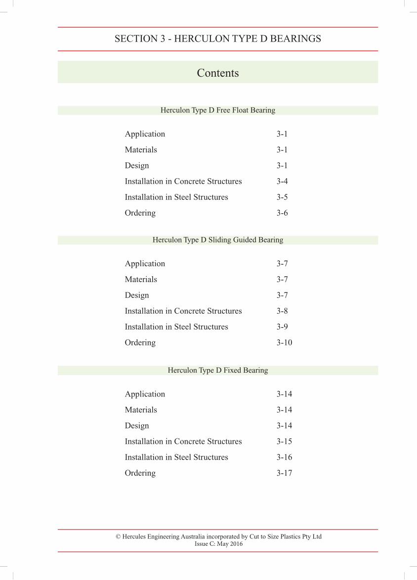
Herculon Type D Free Float Bearing 3-1
Herculon Type D Sliding Guided Bearing 3-7
Herculon Type D Fixed Bearing 3-14
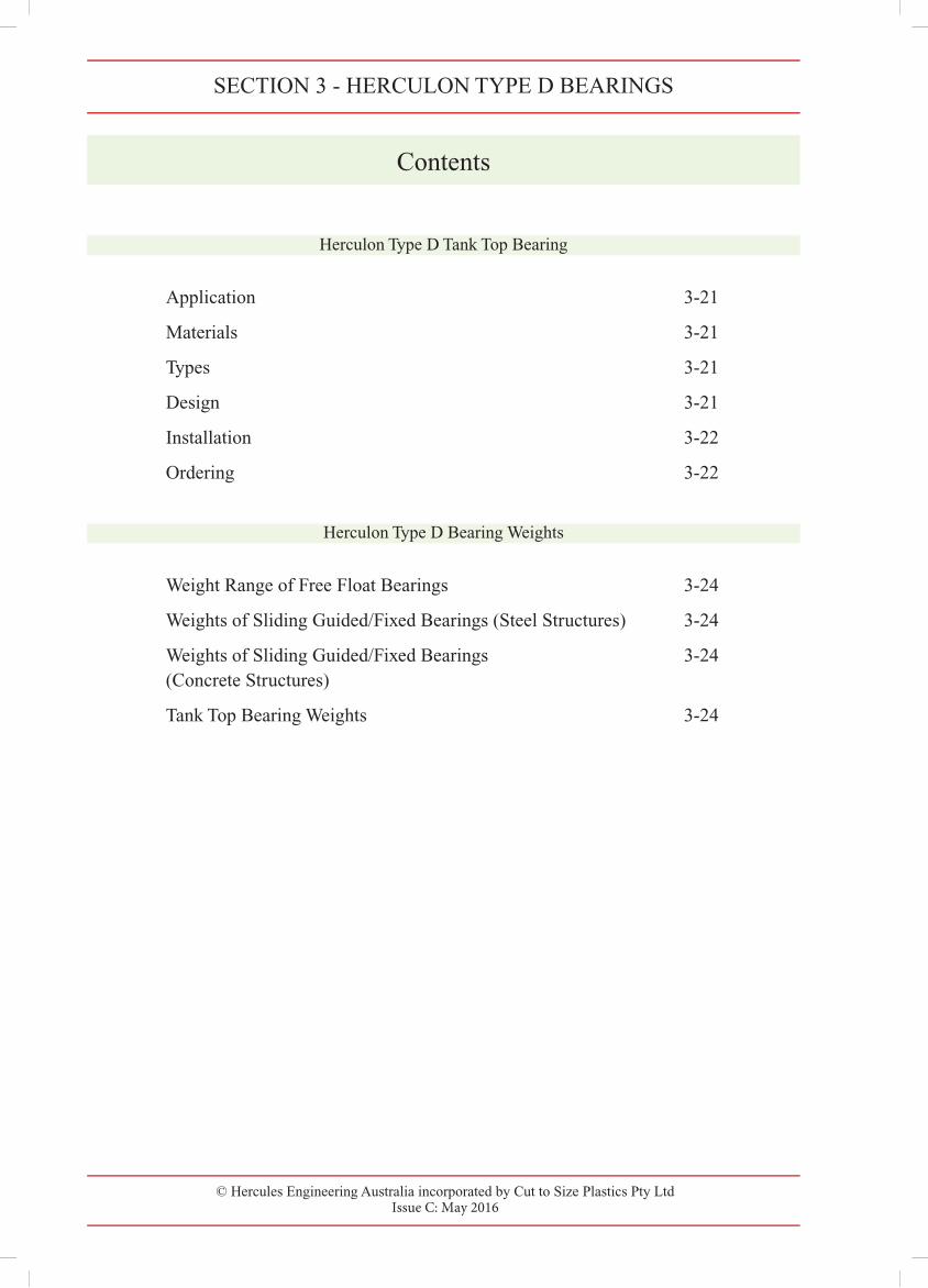
Herculon Type D Tank Top Bearing 3-21
Herculon Type D Bearing Weights 3-24
Hercules Grease Slipjoints 1-9

© Hercules Engineering Australia incorporated by Cut to Size Plastics Pty Ltd Issue C: May 2016
SECTION 1 - CONTINUOUS SLIPJOINTS AND SHEARSTRIPS
Contents
Application 1-1
Materials 1-1
Types 1-1
Design 1-1
Installation 1-2
Ordering 1-2
Hercules Shearstrip
Application 1-5
Materials 1-5
Types 1-5
Design 1-5
Installation 1-6
Ordering 1-7
Shipping Weights for HSC and HSS
Hercuslip Composite 1-8
Hercules Shearstrip 1-8
Hercules Grease Slipjoints
Hercuslip Composite
Application
Materials
Types
Design
Installation
Ordering
1-9
1-9
1-9
1-10
1-10
1-10

© Hercules Engineering Australia incorporated by Cut to Size Plastics Pty Ltd Data Sheet CTSHE/3008/01 - Issue C: May 2016
Hercuslip Composite 1-1Hercuslip Composite 1-1
© Cut to Size Plastics Pty Ltd incorporating Hercules Engineering AustraliaData Sheet CTSHE/3008/00 - Issue A: November 2000
1
Application
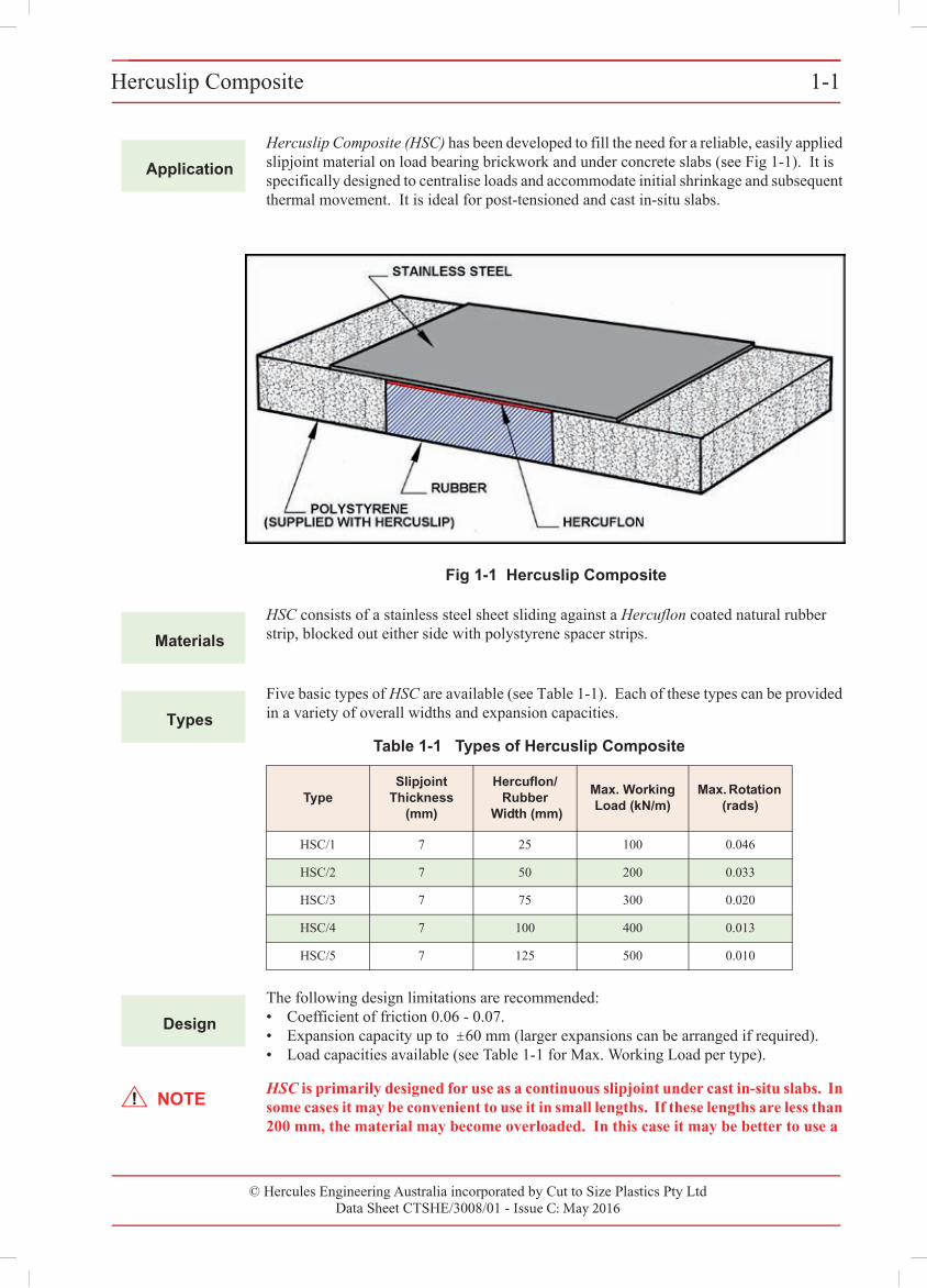
Hercuslip Composite (HSC) has been developed to fill the need for a reliable, easily applied slipjoint material on load bearing brickwork and under concrete slabs (see Fig 1-1). It is specifically designed to centralise loads and accommodate initial shrinkage and subsequent thermal movement. It is ideal for post-tensioned and cast in-situ slabs.
Fig 1-1 Hercuslip Composite
Materials
HSC consists of a stainless steel sheet sliding against a Hercuflon coated natural rubber strip, blocked out either side with polystyrene spacer strips.
Types
Five basic types of HSC are available (see Table 1-1). Each of these types can be provided in a variety of overall widths and expansion capacities.
Table 1-1 Types of Hercuslip Composite
TypeSlipjoint
Thickness (mm)
Hercuflon/Rubber
Width (mm)
Max. Working Load (kN/m)
Max. Rotation (rads)
HSC/1 7 25 100 0.046
HSC/2 7 50 200 0.033
HSC/3 7 75 300 0.020
HSC/4 7 100 400 0.013
HSC/5 7 125 500 0.010
Design
The following design limitations are recommended:• Coefficient of friction 0.06 - 0.07.• Expansion capacity up to ± 60 mm (larger expansions can be arranged if required).• Load capacities available (see Table 1-1 for Max. Working Load per type).
NOTEHSC is primarily designed for use as a continuous slipjoint under cast in-situ slabs. In some cases it may be convenient to use it in small lengths. If these lengths are less than 200 mm, the material may become overloaded. In this case it may be better to use a
1-2 Hercuslip Composite
© Cut to Size Plastics Pty Ltd incorporating Hercules Engineering AustraliaData Sheet CTSHE/3008/00 - Issue A: November 2000
small Herculon Bearing. The standard material should NOT be used under pre-cast elements, a modified version being available for this situation. If in any doubt, please contact our Technical Department.
Installation
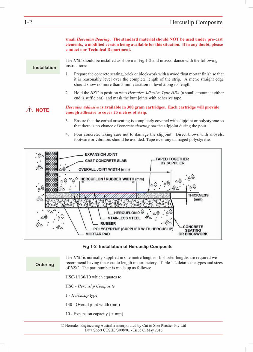
The HSC should be installed as shown in Fig 1-2 and in accordance with the following instructions:
1. Prepare the concrete seating, brick or blockwork with a wood float mortar finish so that it is reasonably level over the complete length of the strip. A metre straight edge should show no more than 3 mm variation in level along its length.
2. Hold the HSC in position with Hercules Adhesive Type HBA (a small amount at either end is sufficient), and mask the butt joints with adhesive tape.
NOTEHercules Adhesive is available in 300 gram cartridges. Each cartridge will provide enough adhesive to cover 25 metres of strip.
3. Ensure that the corbal or seating is completely covered with slipjoint or polystyrene so that there is no chance of concrete shorting out the slipjoint during the pour.
4. Pour concrete, taking care not to damage the slipjoint. Direct blows with shovels, footware or vibrators should be avoided. Tape over any damaged polystyrene.
Fig 1-2 Installation of Hercuslip Composite
Ordering
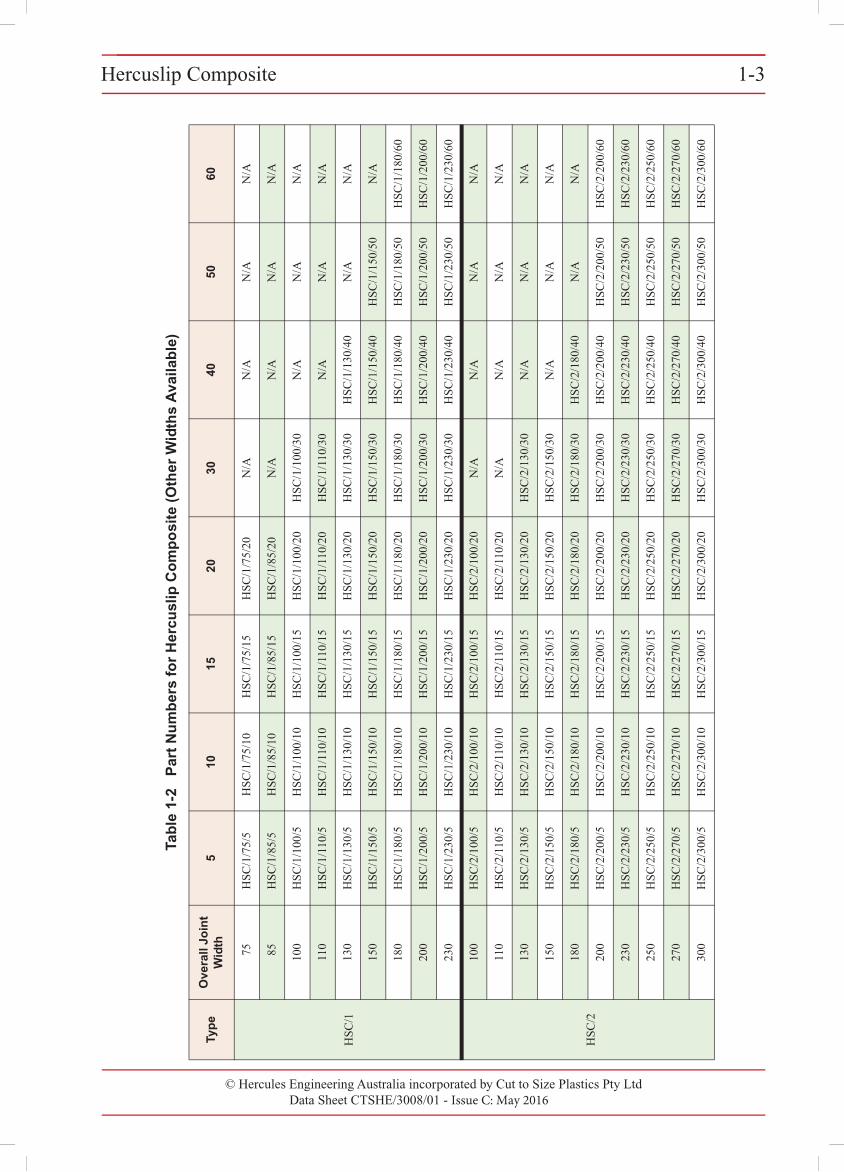
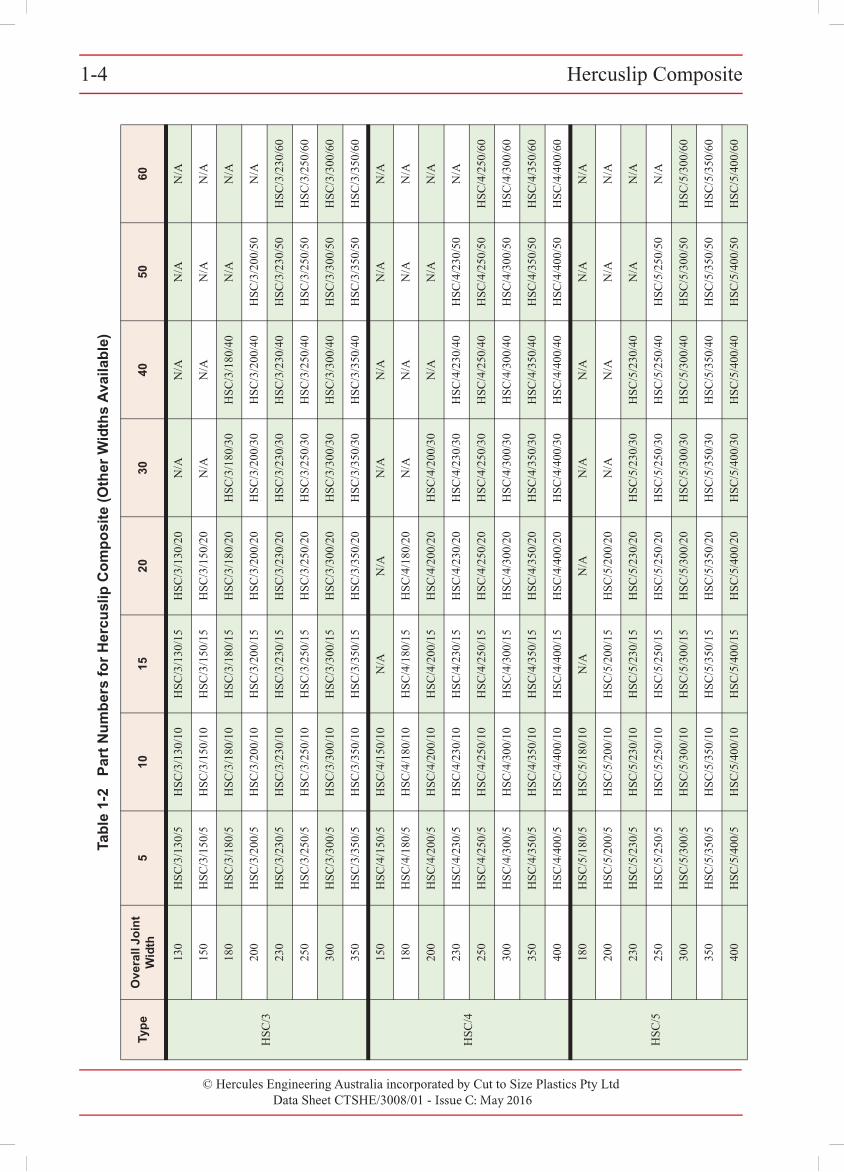
The HSC is normally supplied in one metre lengths. If shorter lengths are required we recommend having these cut to length in our factory. Table 1-2 details the types and sizes of HSC. The part number is made up as follows:
HSC/1/130/10 which equates to:
HSC - Hercuslip Composite
1 - Hercuslip type
130 - Overall joint width (mm)
10 - Expansion capacity ( ± mm)
© Hercules Engineering Australia incorporated by Cut to Size Plastics Pty Ltd Data Sheet CTSHE/3008/01 - Issue C: May 2016
Hercuslip Composite1-21-2 Hercuslip Composite
© Cut to Size Plastics Pty Ltd incorporating Hercules Engineering AustraliaData Sheet CTSHE/3008/00 - Issue A: November 2000
small Herculon Bearing. The standard material should NOT be used under pre-cast elements, a modified version being available for this situation. If in any doubt, please contact our Technical Department.
Installation
The HSC should be installed as shown in Fig 1-2 and in accordance with the following instructions:
1. Prepare the concrete seating, brick or blockwork with a wood float mortar finish so that it is reasonably level over the complete length of the strip. A metre straight edgeshould show no more than 3 mm variation in level along its length.
2. Hold the HSC in position with Hercules Adhesive Type HBA (a small amount at eitherend is sufficient), and mask the butt joints with adhesive tape.
NOTEHercules Adhesive is available in 300 gram cartridges. Each cartridge will provide enough adhesive to cover 25 metres of strip.
3. Ensure that the corb l or seating is completely covered with slipjoint or polystyrene sothat there is no chance of concrete shorting out the slipjoint during the pour.
4. Pour concrete, taking care not to damage the slipjoint. Direct blows with shovels,footware or vibrators should be avoided. Tape over any damaged polystyrene.
Fig 1-2 Installation of Hercuslip Composite
Ordering
The HSC is normally supplied in one metre lengths. If shorter lengths are required we recommend having these cut to length in our factory. Table 1-2 details the types and sizesof HSC. The part number is made up as follows:
HSC/1/130/10 which equates to:
HSC - Hercuslip Composite
1 - Hercuslip type
130 - Overall joint width (mm)
10 - Expansion capacity ( ± mm)
e
© Hercules Engineering Australia incorporated by Cut to Size Plastics Pty LtdData Sheet CTSHE/3008/01 - Issue C: May 2016
Hercuslip Composite 1-3Hercuslip Composite 1-3
© Cut to Size Plastics Pty Ltd incorporating Hercules Engineering AustraliaData Sheet CTSHE/3008/00 - Issue A: November 2000
Tab
le 1
-2
Par
t N
um
ber
s fo
r H
ercu
slip
Co
mp
osi
te (
Oth
er W
idth
s A
vaila
ble
)
Typ
eO
vera
ll Jo
int
Wid
th5
1015
2030
4050
60
HSC
/1
75H
SC/1
/75/
5H
SC/1
/75/
10H
SC/1
/75/
15H
SC/1
/75/
20N
/AN
/AN
/AN
/A
85H
SC/1
/85/
5H
SC/1
/85/
10H
SC/1
/85/
15H
SC/1
/85/
20N
/AN
/AN
/AN
/A
100
HSC
/1/1
00/5
HSC
/1/1
00/1
0H
SC/1
/100
/15
HSC
/1/1
00/2
0H
SC/1
/100
/30
N/A
N/A
N/A
110
HSC
/1/1
10/5
HSC
/1/1
10/1
0H
SC/1
/110
/15
HSC
/1/1
10/2
0H
SC/1
/110
/30
N/A
N/A
N/A
130
HSC
/1/1
30/5
HSC
/1/1
30/1
0H
SC/1
/130
/15
HSC
/1/1
30/2
0H
SC/1
/130
/30
HSC
/1/1
30/4
0N
/AN
/A
150
HSC
/1/1
50/5
HSC
/1/1
50/1
0H
SC/1
/150
/15
HSC
/1/1
50/2
0H
SC/1
/150
/30
HSC
/1/1
50/4
0H
SC/1
/150
/50
N/A
180
HSC
/1/1
80/5
HSC
/1/1
80/1
0H
SC/1
/180
/15
HSC
/1/1
80/2
0H
SC/1
/180
/30
HSC
/1/1
80/4
0H
SC/1
/180
/50
HSC
/1/1
80/6
0
200
HSC
/1/2
00/5
HSC
/1/2
00/1
0H
SC/1
/200
/15
HSC
/1/2
00/2
0H
SC/1
/200
/30
HSC
/1/2
00/4
0H
SC/1
/200
/50
HSC
/1/2
00/6
0
230
HSC
/1/2
30/5
HSC
/1/2
30/1
0H
SC/1
/230
/15
HSC
/1/2
30/2
0H
SC/1
/230
/30
HSC
/1/2
30/4
0H
SC/1
/230
/50
HSC
/1/2
30/6
0
HSC
/2
100
HSC
/2/1
00/5
HSC
/2/1
00/1
0H
SC/2
/100
/15
HSC
/2/1
00/2
0N
/AN
/AN
/AN
/A
110
HSC
/2/1
10/5
HSC
/2/1
10/1
0H
SC/2
/110
/15
HSC
/2/1
10/2
0N
/AN
/AN
/AN
/A
130
HSC
/2/1
30/5
HSC
/2/1
30/1
0H
SC/2
/130
/15
HSC
/2/1
30/2
0H
SC/2
/130
/30
N/A
N/A
N/A
150
HSC
/2/1
50/5
HSC
/2/1
50/1
0H
SC/2
/150
/15
HSC
/2/1
50/2
0H
SC/2
/150
/30
N/A
N/A
N/A
180
HSC
/2/1
80/5
HSC
/2/1
80/1
0H
SC/2
/180
/15
HSC
/2/1
80/2
0H
SC/2
/180
/30
HSC
/2/1
80/4
0N
/AN
/A
200
HSC
/2/2
00/5
HSC
/2/2
00/1
0H
SC/2
/200
/15
HSC
/2/2
00/2
0H
SC/2
/200
/30
HSC
/2/2
00/4
0H
SC/2
/200
/50
HSC
/2/2
00/6
0
230
HSC
/2/2
30/5
HSC
/2/2
30/1
0H
SC/2
/230
/15
HSC
/2/2
30/2
0H
SC/2
/230
/30
HSC
/2/2
30/4
0H
SC/2
/230
/50
HSC
/2/2
30/6
0
250
HSC
/2/2
50/5
HSC
/2/2
50/1
0H
SC/2
/250
/15
HSC
/2/2
50/2
0H
SC/2
/250
/30
HSC
/2/2
50/4
0H
SC/2
/250
/50
HSC
/2/2
50/6
0
270
HSC
/2/2
70/5
HSC
/2/2
70/1
0H
SC/2
/270
/15
HSC
/2/2
70/2
0H
SC/2
/270
/30
HSC
/2/2
70/4
0H
SC/2
/270
/50
HSC
/2/2
70/6
0
300
HSC
/2/3
00/5
HSC
/2/3
00/1
0H
SC/2
/300
/15
HSC
/2/3
00/2
0H
SC/2
/300
/30
HSC
/2/3
00/4
0H
SC/2
/300
/50
HSC
/2/3
00/6
0
© Hercules Engineering Australia incorporated by Cut to Size Plastics Pty LtdData Sheet CTSHE/3008/01 - Issue C: May 2016
Hercuslip Composite1-41-4 Hercuslip Composite
© Cut to Size Plastics Pty Ltd incorporating Hercules Engineering AustraliaData Sheet CTSHE/3008/00 - Issue A: November 2000
HSC
/3
130
HSC
/3/1
30/5
HSC
/3/1
30/1
0H
SC/3
/130
/15
HSC
/3/1
30/2
0N
/AN
/AN
/AN
/A
150
HSC
/3/1
50/5
HSC
/3/1
50/1
0H
SC/3
/150
/15
HSC
/3/1
50/2
0N
/AN
/AN
/AN
/A
180
HSC
/3/1
80/5
HSC
/3/1
80/1
0H
SC/3
/180
/15
HSC
/3/1
80/2
0H
SC/3
/180
/30
HSC
/3/1
80/4
0N
/AN
/A
200
HSC
/3/2
00/5
HSC
/3/2
00/1
0H
SC/3
/200
/15
HSC
/3/2
00/2
0H
SC/3
/200
/30
HSC
/3/2
00/4
0H
SC/3
/200
/50
N/A
230
HSC
/3/2
30/5
HSC
/3/2
30/1
0H
SC/3
/230
/15
HSC
/3/2
30/2
0H
SC/3
/230
/30
HSC
/3/2
30/4
0H
SC/3
/230
/50
HSC
/3/2
30/6
0
250
HSC
/3/2
50/5
HSC
/3/2
50/1
0H
SC/3
/250
/15
HSC
/3/2
50/2
0H
SC/3
/250
/30
HSC
/3/2
50/4
0H
SC/3
/250
/50
HSC
/3/2
50/6
0
300
HSC
/3/3
00/5
HSC
/3/3
00/1
0H
SC/3
/300
/15
HSC
/3/3
00/2
0H
SC/3
/300
/30
HSC
/3/3
00/4
0H
SC/3
/300
/50
HSC
/3/3
00/6
0
350
HSC
/3/3
50/5
HSC
/3/3
50/1
0H
SC/3
/350
/15
HSC
/3/3
50/2
0H
SC/3
/350
/30
HSC
/3/3
50/4
0H
SC/3
/350
/50
HSC
/3/3
50/6
0
HSC
/4
150
HSC
/4/1
50/5
HSC
/4/1
50/1
0N
/AN
/AN
/AN
/AN
/AN
/A
180
HSC
/4/1
80/5
HSC
/4/1
80/1
0H
SC/4
/180
/15
HSC
/4/1
80/2
0N
/AN
/AN
/AN
/A
200
HSC
/4/2
00/5
HSC
/4/2
00/1
0H
SC/4
/200
/15
HSC
/4/2
00/2
0H
SC/4
/200
/30
N/A
N/A
N/A
230
HSC
/4/2
30/5
HSC
/4/2
30/1
0H
SC/4
/230
/15
HSC
/4/2
30/2
0H
SC/4
/230
/30
HSC
/4/2
30/4
0H
SC/4
/230
/50
N/A
250
HSC
/4/2
50/5
HSC
/4/2
50/1
0H
SC/4
/250
/15
HSC
/4/2
50/2
0H
SC/4
/250
/30
HSC
/4/2
50/4
0H
SC/4
/250
/50
HSC
/4/2
50/6
0
300
HSC
/4/3
00/5
HSC
/4/3
00/1
0H
SC/4
/300
/15
HSC
/4/3
00/2
0H
SC/4
/300
/30
HSC
/4/3
00/4
0H
SC/4
/300
/50
HSC
/4/3
00/6
0
350
HSC
/4/3
50/5
HSC
/4/3
50/1
0H
SC/4
/350
/15
HSC
/4/3
50/2
0H
SC/4
/350
/30
HSC
/4/3
50/4
0H
SC/4
/350
/50
HSC
/4/3
50/6
0
400
HSC
/4/4
00/5
HSC
/4/4
00/1
0H
SC/4
/400
/15
HSC
/4/4
00/2
0H
SC/4
/400
/30
HSC
/4/4
00/4
0H
SC/4
/400
/50
HSC
/4/4
00/6
0
HSC
/5
180
HSC
/5/1
80/5
HSC
/5/1
80/1
0N
/AN
/AN
/AN
/AN
/AN
/A
200
HSC
/5/2
00/5
HSC
/5/2
00/1
0H
SC/5
/200
/15
HSC
/5/2
00/2
0N
/AN
/AN
/AN
/A
230
HSC
/5/2
30/5
HSC
/5/2
30/1
0H
SC/5
/230
/15
HSC
/5/2
30/2
0H
SC/5
/230
/30
HSC
/5/2
30/4
0N
/AN
/A
250
HSC
/5/2
50/5
HSC
/5/2
50/1
0H
SC/5
/250
/15
HSC
/5/2
50/2
0H
SC/5
/250
/30
HSC
/5/2
50/4
0H
SC/5
/250
/50
N/A
300
HSC
/5/3
00/5
HSC
/5/3
00/1
0H
SC/5
/300
/15
HSC
/5/3
00/2
0H
SC/5
/300
/30
HSC
/5/3
00/4
0H
SC/5
/300
/50
HSC
/5/3
00/6
0
350
HSC
/5/3
50/5
HSC
/5/3
50/1
0H
SC/5
/350
/15
HSC
/5/3
50/2
0H
SC/5
/350
/30
HSC
/5/3
50/4
0H
SC/5
/350
/50
HSC
/5/3
50/6
0
400
HSC
/5/4
00/5
HSC
/5/4
00/1
0H
SC/5
/400
/15
HSC
/5/4
00/2
0H
SC/5
/400
/30
HSC
/5/4
00/4
0H
SC/5
/400
/50
HSC
/5/4
00/6
0
Tab
le 1
-2
Par
t N
um
ber
s fo
r H
ercu
slip
Co
mp
osi
te (
Oth
er W
idth
s A
vaila
ble
)
Typ
eO
vera
ll Jo
int
Wid
th5
1015
2030
4050
60
© Hercules Engineering Australia incorporated by Cut to Size Plastics Pty Ltd Data Sheet CTSHE/3009/01 - Issue C: May 2016
Hercules Shearstrip 1-5Hercules Shearstrip 1-5
© Cut to Size Plastics Pty Ltd incorporating Hercules Engineering AustraliaData Sheet CTSHE/3009/00 - Issue A: November 2000
1
Application
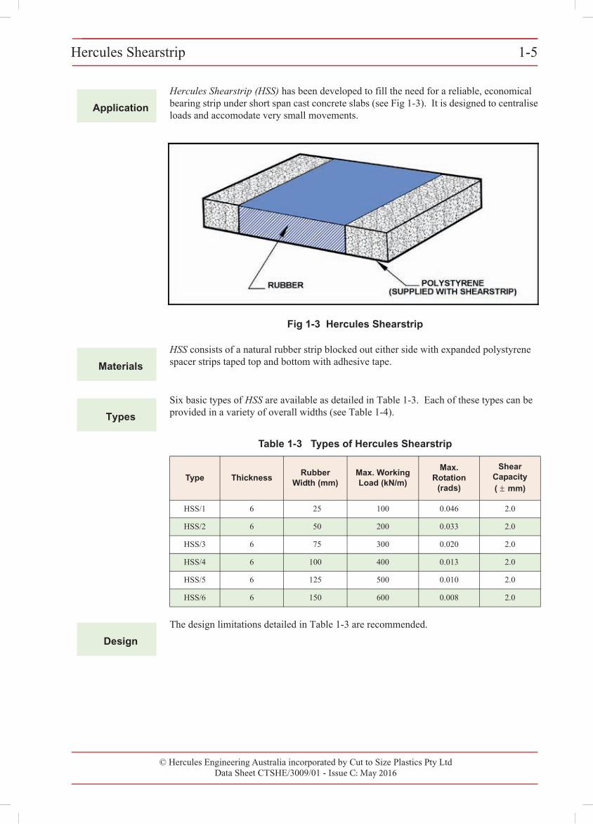
Hercules Shearstrip (HSS) has been developed to fill the need for a reliable, economical bearing strip under short span cast concrete slabs (see Fig 1-3). It is designed to centralise loads and accomodate very small movements.
Fig 1-3 Hercules Shearstrip
Materials
HSS consists of a natural rubber strip blocked out either side with expanded polystyrene spacer strips taped top and bottom with adhesive tape.
Types
Six basic types of HSS are available as detailed in Table 1-3. Each of these types can be provided in a variety of overall widths (see Table 1-4).
Table 1-3 Types of Hercules Shearstrip
Type ThicknessRubber
Width (mm)Max. Working Load (kN/m)
Max. Rotation
(rads)
Shear Capacity ( ± mm)
HSS/1 6 25 100 0.046 2.0
HSS/2 6 50 200 0.033 2.0
HSS/3 6 75 300 0.020 2.0
HSS/4 6 100 400 0.013 2.0
HSS/5 6 125 500 0.010 2.0
HSS/6 6 150 600 0.008 2.0
Design
The design limitations detailed in Table 1-3 are recommended.
© Hercules Engineering Australia incorporated by Cut to Size Plastics Pty LtdData Sheet CTSHE/3009/01 - Issue C: May 2016
Hercules Shearstrip1-61-6 Hercules Shearstrip
© Cut to Size Plastics Pty Ltd incorporating Hercules Engineering AustraliaData Sheet CTSHE/3009/00 - Issue A: November 2000
Installation
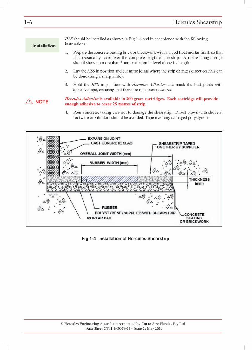
HSS should be installed as shown in Fig 1-4 and in accordance with the following instructions:
1. Prepare the concrete seating brick or blockwork with a wood float mortar finish so thatit is reasonably level over the complete length of the strip. A metre straight edgeshould show no more than 3 mm variation in level along its length.
2. Lay the HSS in position and cut mitre joints where the strip changes direction (this canbe done using a sharp knife).
3. Hold the HSS in position with Hercules Adhesive and mask the butt joints withadhesive tape, ensuring that there are no concrete shorts.
NOTEHercules Adhesive is available in 300 gram cartridges. Each cartridge will provide enough adhesive to cover 25 metres of strip.
4. Pour concrete, taking care not to damage the shearstrip. Direct blows with shovels,footware or vibrators should be avoided. Tape over any damaged polystyrene.
Fig 1-4 Installation of Hercules Shearstrip
© Hercules Engineering Australia incorporated by Cut to Size Plastics Pty LtdData Sheet CTSHE/3009/01 - Issue C: May 2016
Hercules Shearstrip 1-7Hercules Shearstrip 1-7
© Cut to Size Plastics Pty Ltd incorporating Hercules Engineering AustraliaData Sheet CTSHE/3009/00 - Issue A: November 2000
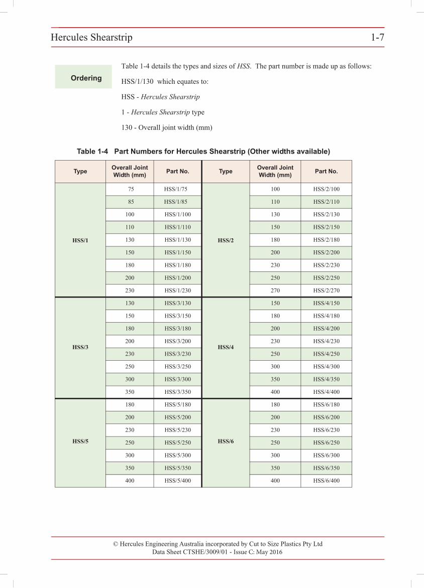
Ordering
Table 1-4 details the types and sizes of HSS. The part number is made up as follows:
HSS/1/130 which equates to:
HSS - Hercules Shearstrip
1 - Hercules Shearstrip type
130 - Overall joint width (mm)
Table 1-4 Part Numbers for Hercules Shearstrip (Other widths available)
TypeOverall Joint Width (mm)
Part No. TypeOverall Joint Width (mm)
Part No.
HSS/1
75 HSS/1/75
HSS/2
100 HSS/2/100
85 HSS/1/85 110 HSS/2/110
100 HSS/1/100 130 HSS/2/130
110 HSS/1/110 150 HSS/2/150
130 HSS/1/130 180 HSS/2/180
150 HSS/1/150 200 HSS/2/200
180 HSS/1/180 230 HSS/2/230
200 HSS/1/200 250 HSS/2/250
230 HSS/1/230 270 HSS/2/270
HSS/3
130 HSS/3/130
HSS/4
150 HSS/4/150
150 HSS/3/150 180 HSS/4/180
180 HSS/3/180 200 HSS/4/200
200 HSS/3/200 230 HSS/4/230
230 HSS/3/230 250 HSS/4/250
250 HSS/3/250 300 HSS/4/300
300 HSS/3/300 350 HSS/4/350
350 HSS/3/350 400 HSS/4/400
HSS/5
180 HSS/5/180
HSS/6
180 HSS/6/180
200 HSS/5/200 200 HSS/6/200
230 HSS/5/230 230 HSS/6/230
250 HSS/5/250 250 HSS/6/250
300 HSS/5/300 300 HSS/6/300
350 HSS/5/350 350 HSS/6/350
400 HSS/5/400 400 HSS/6/400
© Hercules Engineering Australia incorporated by Cut to Size Plastics Pty LtdData Sheet CTSHE/3008/01 & 3009/01 - Issue C: May 2016
1-8 Shipping Weights for HSC and HSS1-8 Shipping Weights for HSC and HSS
© Cut to Size Plastics Pty Ltd incorporating Hercules Engineering AustraliaData Sheet CTSHE/3008/00 & 3009/00 - Issue A: November 2000
1
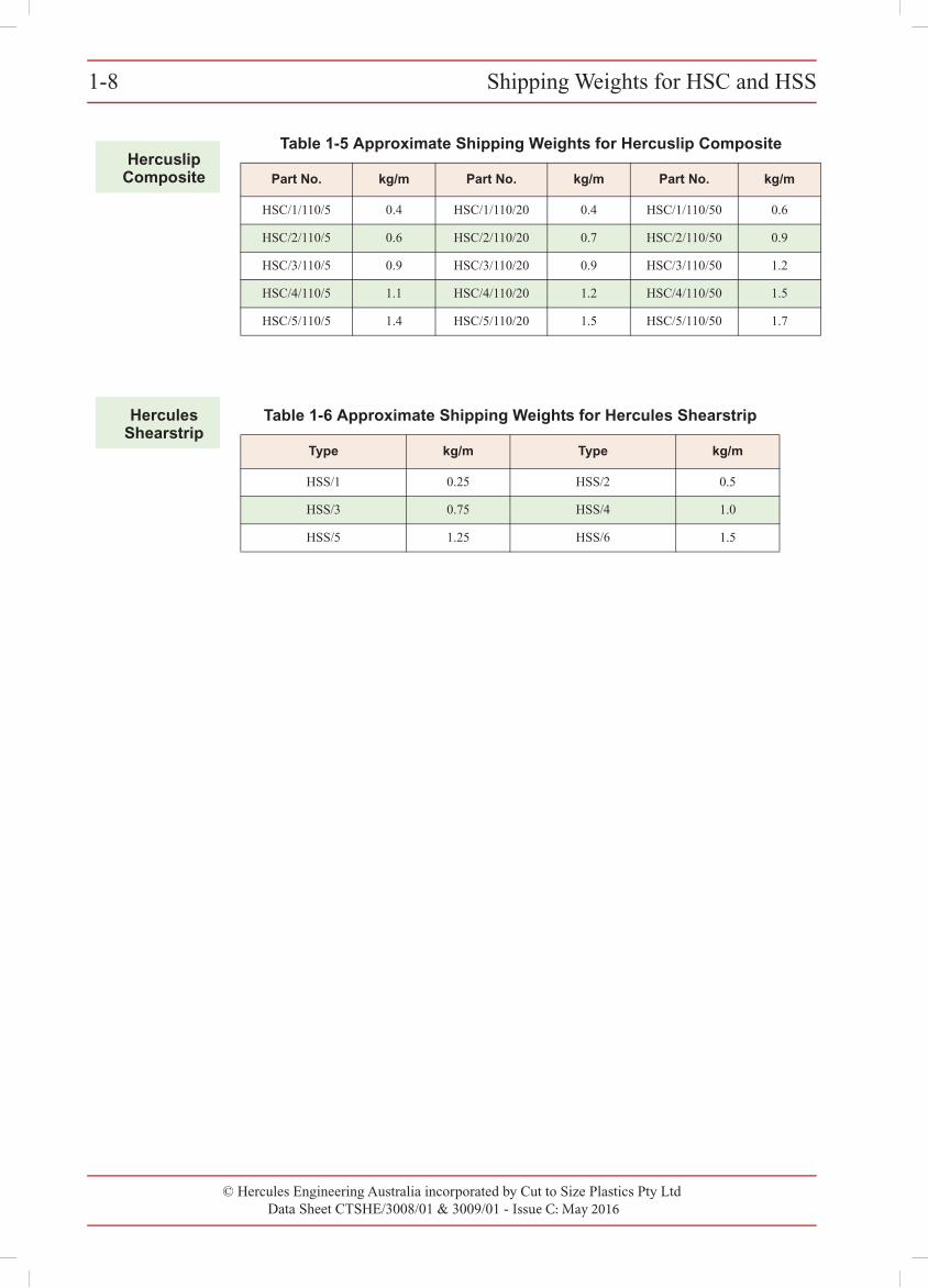
Table 1-5 Approximate Shipping Weights for Hercuslip Composite
Part No. kg/m Part No. kg/m Part No. kg/m
HSC/1/110/5 0.4 HSC/1/110/20 0.4 HSC/1/110/50 0.6
HSC/2/110/5 0.6 HSC/2/110/20 0.7 HSC/2/110/50 0.9
HSC/3/110/5 0.9 HSC/3/110/20 0.9 HSC/3/110/50 1.2
HSC/4/110/5 1.1 HSC/4/110/20 1.2 HSC/4/110/50 1.5
HSC/5/110/5 1.4 HSC/5/110/20 1.5 HSC/5/110/50 1.7
Table 1-6 Approximate Shipping Weights for Hercules Shearstrip
Type kg/m Type kg/m
HSS/1 0.25 HSS/2 0.5
HSS/3 0.75 HSS/4 1.0
HSS/5 1.25 HSS/6 1.5
HercuslipComposite
HerculesShearstrip
Hercules Grease Slipjoints 1 - 9
© Hercules Engineering Australia incorporated by Cut To Size Plastics Pty Ltd
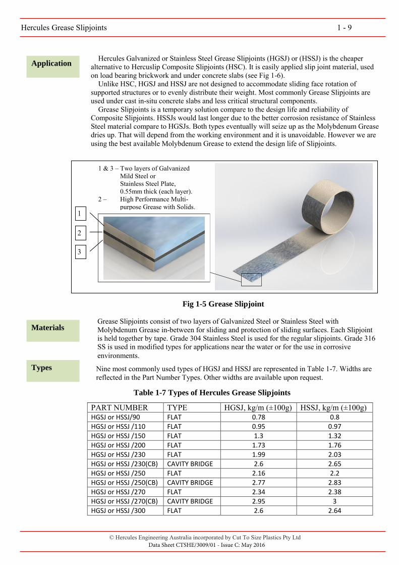
Application Hercules Galvanized or Stainless Steel Grease Slipjoints (HGSJ) or (HSSJ) is the cheaper alternative to Hercuslip Composite Slipjoints (HSC). It is easily applied slip joint material, used on load bearing brickwork and under concrete slabs (see Fig 1-6). Unlike HSC, HGSJ and HSSJ are not designed to accommodate sliding face rotation of supported structures or to evenly distribute their weight. Most commonly Grease Slipjoints are used under cast in-situ concrete slabs and less critical structural components. Grease Slipjoints is a temporary solution compare to the design life and reliability of Composite Slipjoints. HSSJs would last longer due to the better corrosion resistance of Stainless Steel material compare to HGSJs. Both types eventually will seize up as the Molybdenum Grease dries up. That will depend from the working environment and it is unavoidable. However we are using the best available Molybdenum Grease to extend the design life of Slipjoints.
1
2
3
1 & 3 – Two layers of Galvanized Mild Steel or Stainless Steel Plate, 0.55mm thick (each layer).
2 – High Performance Multi- purpose Grease with Solids.
Fig 1-5 Grease Slipjoint
Materials
Types
Grease Slipjoints consist of two layers of Galvanized Steel or Stainless Steel with Molybdenum Grease in-between for sliding and protection of sliding surfaces. Each Slipjoint is held together by tape. Grade 304 Stainless Steel is used for the regular slipjoints. Grade 316 SS is used in modified types for applications near the water or for the use in corrosive environments.
Nine most commonly used types of HGSJ and HSSJ are represented in Table 1-7. Widths are reflected in the Part Number Types. Other widths are available upon request.
PART NUMBER TYPE HGSJ, kg/m (±100g) HSSJ, kg/m (±100g) HGSJ or HSSJ/90 FLAT 0.78 0.8
HGSJ or HSSJ /110 FLAT 0.95 0.97
HGSJ or HSSJ /150 FLAT 1.3 1.32
HGSJ or HSSJ /200 FLAT 1.73 1.76
HGSJ or HSSJ /230 FLAT 1.99 2.03
HGSJ or HSSJ /230(CB) CAVITY BRIDGE 2.6 2.65
HGSJ or HSSJ /250 FLAT 2.16 2.2
HGSJ or HSSJ /250(CB) CAVITY BRIDGE 2.77 2.83
HGSJ or HSSJ /270 FLAT 2.34 2.38
HGSJ or HSSJ /270(CB) CAVITY BRIDGE 2.95 3
HGSJ or HSSJ /300 FLAT 2.6 2.64
Table 1-7 Types of Hercules Grease Slipjoints
Data Sheet CTSHE/3009/01 - Issue C: May 2016
Hercules Grease Slipjoints 1 - 10
© Hercules Engineering Australia incorporated by Cut To Size Plastics Pty Ltd
Design The following design limitations are recommended: • Coefficient of friction* 0.04 (Zinc-Zinc) - 0.16 (Steel-Steel) • Expansion capacity ±2 to ±5mm • Recommended contact stress** 100 – 150MPa • Operating Temperature Range -25°C to +120°C (peak +130°C) • Dropping Point for Grease +175°C
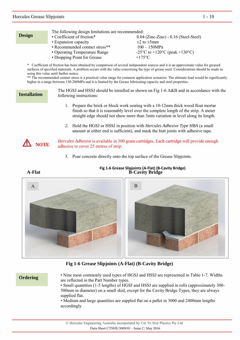
Fig 1-6 Grease Slipjoints (A-Flat) (B-Cavity Bridge)
Installation
Ordering
The HGSJ and HSSJ should be installed as shown on Fig 1-6 A&B and in accordance with the following instructions:
1. Prepare the brick or block work seating with a 10-12mm thick wood float mortarfinish so that it is reasonably level over the complete length of the strip. A meterstraight edge should not show more than 3mm variation in level along its length.
2. Hold the HGSJ or HSSJ in position with Hercules Adhesive Type HBA (a smallamount at either end is sufficient), and mask the butt joints with adhesive tape.
Hercules Adhesive is available in 300 gram cartridges. Each cartridge will provide enough adhesive to cover 25 metres of strip.
3. Pour concrete directly onto the top surface of the Grease Slipjoints.
Fig 1-6 Grease Slipjoints (A-Flat) (B-Cavity Bridge)
• Nine most commonly used types of HGSJ and HSSJ are represented in Table 1-7. Widthsare reflected in the Part Number types. • Small quantities (1-5 lengths) of HGSJ and HSSJ are supplied in rolls (approximately 300-500mm in diameter) on a small skid, except for the Cavity Bridge Types, they are always supplied flat. • Medium and large quantities are suppled flat on a pallet in 3000 and 2400mm lengths
accordingly.
A B
NOTE
A-Flat B-Cavity Bridge
* Coefficient of friction has been obtained by comparison of several independent sources and it is an approximate value for greasedsurfaces of specified materials. A problem occurs with the value concerning the type of grease used. Considerations should be made in using this value until further notice. ** The recommended contact stress is a practical value range for common application scenarios. The ultimate load would be significantly higher in a range between 150-200MPa and it is limited by the Grease lubricating capacity and steel properties.
Data Sheet CTSHE/3009/01 - Issue C: May 2016
© Hercules Engineering Australia incorporated by Cut to Size Plastics Pty Ltd Issue C: May 2016
SECTION 2 - HERCULON MODIFIED BEARINGS
Contents
Herculon Modified Type B Bearing
Application 2-1
Materials 2-1
Types 2-1
Design 2-1
Installation 2-2
Ordering 2-3
Herculon Modified Type D Bearing
Application 2-6
Materials 2-6
Types 2-6
Design 2-6
Installation 2-7
Ordering 2-8

© Hercules Engineering Australia incorporated by Cut to Size Plastics Pty LtdData Sheet CTSHE/3011/01 - Issue C: May 2016
Herculon Modified Type B Bearing 2-1Herculon Modified Type B Bearing 2-1
© Cut to Size Plastics Pty Ltd incorporating Hercules Engineering AustraliaData Sheet CTSHE/3011/00 - Issue A: November 2000
2
Application
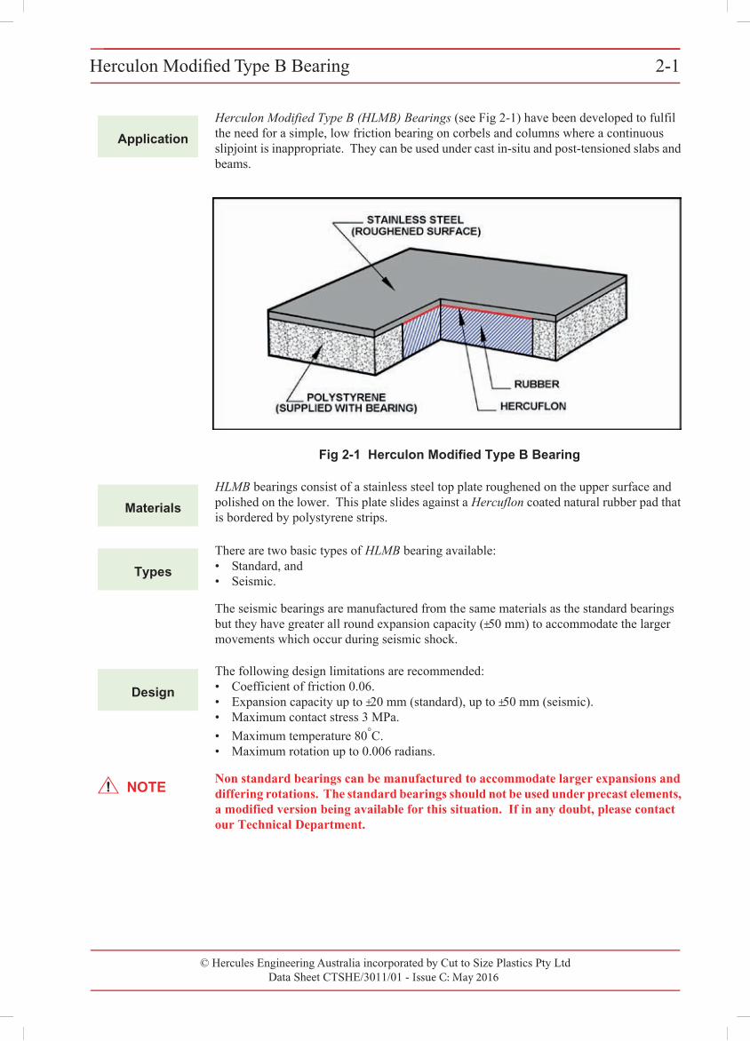
Herculon Modified Type B (HLMB) Bearings (see Fig 2-1) have been developed to fulfil the need for a simple, low friction bearing on corbels and columns where a continuous slipjoint is inappropriate. They can be used under cast in-situ and post-tensioned slabs and beams.
Fig 2-1 Herculon Modified Type B Bearing
Materials
HLMB bearings consist of a stainless steel top plate roughened on the upper surface and polished on the lower. This plate slides against a Hercuflon coated natural rubber pad that is bordered by polystyrene strips.
Types
There are two basic types of HLMB bearing available:• Standard, and• Seismic.
The seismic bearings are manufactured from the same materials as the standard bearings but they have greater all round expansion capacity (±50 mm) to accommodate the larger movements which occur during seismic shock.
Design
The following design limitations are recommended:• Coefficient of friction 0.06.• Expansion capacity up to ±20 mm (standard), up to ±50 mm (seismic).• Maximum contact stress 3 MPa.• Maximum temperature 80°C.• Maximum rotation up to 0.006 radians.
NOTENon standard bearings can be manufactured to accommodate larger expansions and differing rotations. The standard bearings should not be used under precast elements, a modified version being available for this situation. If in any doubt, please contact our Technical Department.
© Hercules Engineering Australia incorporated by Cut to Size Plastics Pty LtdData Sheet CTSHE/3011/01 - Issue C: May 2016
Herculon Modified Type B Bearing2-22-2 Herculon Modified Type B Bearing
© Cut to Size Plastics Pty Ltd incorporating Hercules Engineering AustraliaData Sheet CTSHE/3011/00 - Issue A: November 2000
Installation
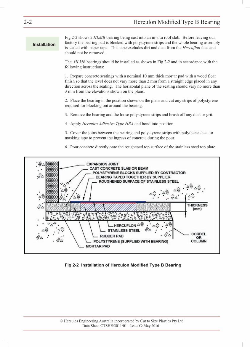
Fig 2-2 shows a HLMB bearing being cast into an in-situ roof slab. Before leaving our factory the bearing pad is blocked with polystyrene strips and the whole bearing assembly is sealed with paper tape. This tape excludes dirt and dust from the Hercuflon face and should not be removed.
The HLMB bearings should be installed as shown in Fig 2-2 and in accordance with the following instructions:
1. Prepare concrete seatings with a nominal 10 mm thick mortar pad with a wood floatfinish so that the level does not vary more than 2 mm from a straight edge placed in any direction across the seating. The horizontal plane of the seating should vary no more than 3 mm from the elevations shown on the plans.
2. Place the bearing in the position shown on the plans and cut any strips of polystyrenerequired for blocking out around the bearing.
3. Remove the bearing and the loose polystyrene strips and brush off any dust or grit.
4. Apply Hercules Adhesive Type HBA and bond into position.
5. Cover the joins between the bearing and polystyrene strips with polythene sheet ormasking tape to prevent the ingress of concrete during the pour.
6. Pour concrete directly onto the roughened top surface of the stainless steel top plate.
Fig 2-2 Installation of Herculon Modified Type B Bearing
© Hercules Engineering Australia incorporated by Cut to Size Plastics Pty LtdData Sheet CTSHE/3011/00 - Issue C: May 2016
Herculon Modified Type B Bearing 2-3Herculon Modified Type B Bearing 2-3
© Cut to Size Plastics Pty Ltd incorporating Hercules Engineering AustraliaData Sheet CTSHE/3011/00 - Issue A: November 2000
Ordering
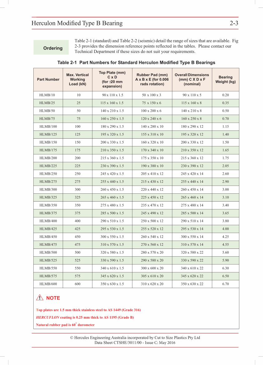
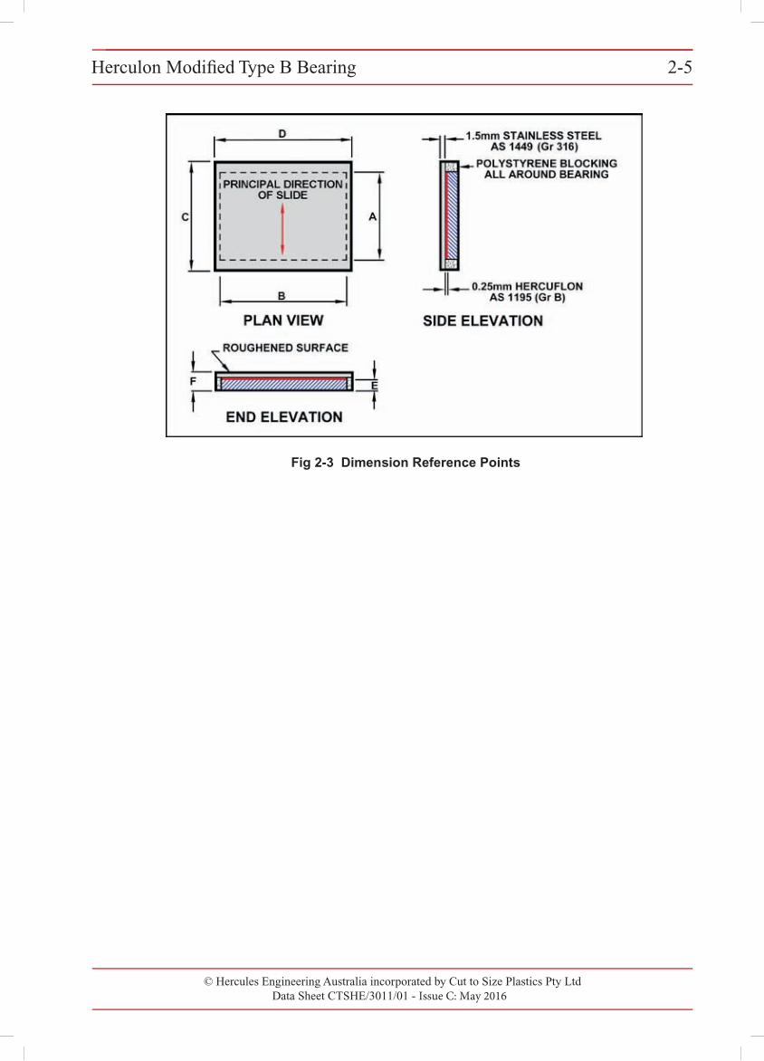
Table 2-1 (standard) and Table 2-2 (seismic) detail the range of sizes that are available. Fig 2-3 provides the dimension reference points reflected in the tables. Please contact our Technical Department if these sizes do not suit your requirements.
Table 2-1 Part Numbers for Standard Herculon Modified Type B Bearings
Part NumberMax. Vertical
WorkingLoad (kN)
Top Plate (mm)C x D
(for ±20 mmexpansion)
Rubber Pad (mm)A x B x E (for 0.006
rads rotation)
Overall Dimensions(mm) C X D x F
(nominal)
BearingWeight (kg)
HLMB/10 10 90 x 110 x 1.5 50 x 100 x 3 90 x 110 x 5 0.20
HLMB/25 25 115 x 160 x 1.5 75 x 150 x 6 115 x 160 x 8 0.35
HLMB/50 50 140 x 210 x 1.5 100 x 200 x 6 140 x 210 x 8 0.50
HLMB/75 75 160 x 250 x 1.5 120 x 240 x 6 160 x 250 x 8 0.70
HLMB/100 100 180 x 290 x 1.5 140 x 280 x 10 180 x 290 x 12 1.15
HLMB/125 125 195 x 320 x 1.5 155 x 310 x 10 195 x 320 x 12 1.40
HLMB/150 150 200 x 330 x 1.5 160 x 320 x 10 200 x 330 x 12 1.50
HLMB/175 175 210 x 350 x 1.5 170 x 340 x 10 210 x 350 x 12 1.65
HLMB/200 200 215 x 360 x 1.5 175 x 350 x 10 215 x 360 x 12 1.75
HLMB/225 225 230 x 390 x 1.5 190 x 380 x 10 230 x 390 x 12 2.05
HLMB/250 250 245 x 420 x 1.5 205 x 410 x 12 245 x 420 x 14 2.60
HLMB/275 275 255 x 440 x 1.5 215 x 430 x 12 255 x 440 x 14 2.90
HLMB/300 300 260 x 450 x 1.5 220 x 440 x 12 260 x 450 x 14 3.00
HLMB/325 325 265 x 460 x 1.5 225 x 450 x 12 265 x 460 x 14 3.10
HLMB/350 350 275 x 480 x 1.5 235 x 470 x 12 275 x 480 x 14 3.40
HLMB/375 375 285 x 500 x 1.5 245 x 490 x 12 285 x 500 x 14 3.65
HLMB/400 400 290 x 510 x 1.5 250 x 500 x 12 290 x 510 x 14 3.80
HLMB/425 425 295 x 530 x 1.5 255 x 520 x 12 295 x 530 x 14 4.00
HLMB/450 450 300 x 550 x 1.5 260 x 540 x 12 300 x 550 x 14 4.25
HLMB/475 475 310 x 570 x 1.5 270 x 560 x 12 310 x 570 x 14 4.55
HLMB/500 500 320 x 580 x 1.5 280 x 570 x 20 320 x 580 x 22 5.60
HLMB/525 525 330 x 590 x 1.5 290 x 580 x 20 330 x 590 x 22 5.90
HLMB/550 550 340 x 610 x 1.5 300 x 600 x 20 340 x 610 x 22 6.30
HLMB/575 575 345 x 620 x 1.5 305 x 610 x 20 345 x 620 x 22 6.50
HLMB/600 600 350 x 630 x 1.5 310 x 620 x 20 350 x 630 x 22 6.70
Top plates are 1.5 mm thick stainless steel to AS 1449 (Grade 316)
HERCUFLON coating is 0.25 mm thick to AS 1195 (Grade B)
Natural rubber pad is 60° durometer
NOTE
Herculon Modified Type B Bearing 2-3
© Cut to Size Plastics Pty Ltd incorporating Hercules Engineering AustraliaData Sheet CTSHE/3011/00 - Issue A: November 2000
Ordering
Table 2-1 (standard) and Table 2-2 (seismic) detail the range of sizes that are available. Fig 2-3 provides the dimension reference points reflected in the tables. Please contact ourTechnical Department if these sizes do not suit your requirements.
Table 2-1 Part Numbers for Standard Herculon Modified Type B Bearings
Part NumberMax. Vertical
Working Load (kN)
Top Plate (mm) C x D
(for ±20 mm expansion)
Rubber Pad (mm) A x B x E (for 0.006
rads rotation)
Overall Dimensions (mm) C X D x F
(nominal)
Bearing Weight (kg)
HLMB/10 10 90 x 110 x 1.5 50 x 100 x 3 90 x 110 x 5 0.20
HLMB/25 25 115 x 160 x 1.5 75 x 150 x 6 115 x 160 x 8 0.35
HLMB/50 50 140 x 210 x 1.5 100 x 200 x 6 140 x 210 x 8 0.50
HLMB/75 75 160 x 250 x 1.5 120 x 240 x 6 160 x 250 x 8 0.70
HLMB/100 100 180 x 290 x 1.5 140 x 280 x 10 180 x 290 x 12 1.15
HLMB/125 125 195 x 320 x 1.5 155 x 310 x 10 195 x 320 x 12 1.40
HLMB/150 150 200 x 330 x 1.5 160 x 320 x 10 200 x 330 x 12 1.50
HLMB/175 175 210 x 350 x 1.5 170 x 340 x 10 210 x 350 x 12 1.65
HLMB/200 200 215 x 360 x 1.5 175 x 350 x 10 215 x 360 x 12 1.75
HLMB/225 225 230 x 390 x 1.5 190 x 380 x 10 230 x 390 x 12 2.05
HLMB/250 250 245 x 420 x 1.5 205 x 410 x 12 245 x 420 x 14 2.60
HLMB/275 275 255 x 440 x 1.5 215 x 430 x 12 255 x 440 x 14 2.90
HLMB/300 300 260 x 450 x 1.5 220 x 440 x 12 260 x 450 x 14 3.00
HLMB/325 325 265 x 460 x 1.5 225 x 450 x 12 265 x 460 x 14 3.10
HLMB/350 350 275 x 480 x 1.5 235 x 470 x 12 275 x 480 x 14 3.40
HLMB/375 375 285 x 500 x 1.5 245 x 490 x 12 285 x 500 x 14 3.65
HLMB/400 400 290 x 510 x 1.5 250 x 500 x 12 290 x 510 x 14 3.80
HLMB/425 425 295 x 530 x 1.5 255 x 520 x 12 295 x 530 x 14 4.00
HLMB/450 450 300 x 550 x 1.5 260 x 540 x 12 300 x 550 x 14 4.25
HLMB/475 475 310 x 570 x 1.5 270 x 560 x 12 310 x 570 x 14 4.55
HLMB/500 500 320 x 580 x 1.5 280 x 570 x 20 320 x 580 x 22 5.60
HLMB/525 525 330 x 590 x 1.5 290 x 580 x 20 330 x 590 x 22 5.90
HLMB/550 550 340 x 610 x 1.5 300 x 600 x 20 340 x 610 x 22 6.30
HLMB/575 575 345 x 620 x 1.5 305 x 610 x 20 345 x 620 x 22 6.50
HLMB/600 600 350 x 630 x 1.5 310 x 620 x 20 350 x 630 x 22 6.70
Top plates are 1.5 mm thick stainless steel to AS 1449 (Grade 316)
HERCUFLON coating is 0.25 mm thick to AS 1195 (Grade B)
Natural rubber pad is 60° durometer
NOTE
© Hercules Engineering Australia incorporated by Cut to Size Plastics Pty LtdData Sheet CTSHE/3011/01 - Issue C: May 2016
Herculon Modified Type B Bearing2-4
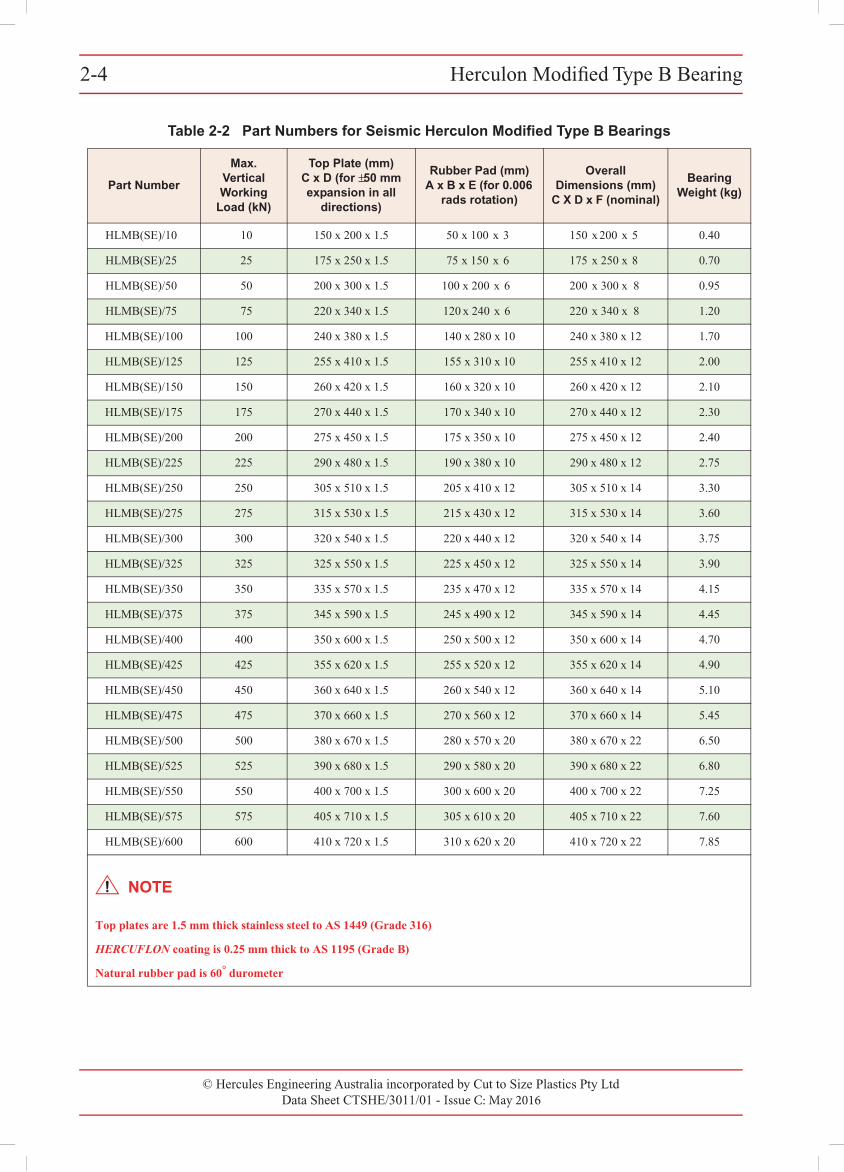
Table 2-2 Part Numbers for Seismic Herculon Modified Type B Bearings
Part Number
Max. Vertical Working
Load (kN)
Top Plate (mm) C x D (for ±50 mm expansion in all
directions)
Rubber Pad (mm) A x B x E (for 0.006
rads rotation)
Overall Dimensions (mm)
C X D x F (nominal)
Bearing Weight (kg)
HLMB(SE)/10 10 150 x 200 x 1.5 50 x 100 x 3 150 x 200 x 5 0.40
HLMB(SE)/25 25 175 x 250 x 1.5 75 x 150 x 6 175 x 250 x 8 0.70
HLMB(SE)/50 50 200 x 300 x 1.5 100 x 200 x 6 200 x 300 x 8 0.95
HLMB(SE)/75 75 220 x 340 x 1.5 120 x 240 x 6 220 x 340 x 8 1.20
HLMB(SE)/100 100 240 x 380 x 1.5 140 x 280 x 10 240 x 380 x 12 1.70
HLMB(SE)/125 125 255 x 410 x 1.5 155 x 310 x 10 255 x 410 x 12 2.00
HLMB(SE)/150 150 260 x 420 x 1.5 160 x 320 x 10 260 x 420 x 12 2.10
HLMB(SE)/175 175 270 x 440 x 1.5 170 x 340 x 10 270 x 440 x 12 2.30
HLMB(SE)/200 200 275 x 450 x 1.5 175 x 350 x 10 275 x 450 x 12 2.40
HLMB(SE)/225 225 290 x 480 x 1.5 190 x 380 x 10 290 x 480 x 12 2.75
HLMB(SE)/250 250 305 x 510 x 1.5 205 x 410 x 12 305 x 510 x 14 3.30
HLMB(SE)/275 275 315 x 530 x 1.5 215 x 430 x 12 315 x 530 x 14 3.60
HLMB(SE)/300 300 320 x 540 x 1.5 220 x 440 x 12 320 x 540 x 14 3.75
HLMB(SE)/325 325 325 x 550 x 1.5 225 x 450 x 12 325 x 550 x 14 3.90
HLMB(SE)/350 350 335 x 570 x 1.5 235 x 470 x 12 335 x 570 x 14 4.15
HLMB(SE)/375 375 345 x 590 x 1.5 245 x 490 x 12 345 x 590 x 14 4.45
HLMB(SE)/400 400 350 x 600 x 1.5 250 x 500 x 12 350 x 600 x 14 4.70
HLMB(SE)/425 425 355 x 620 x 1.5 255 x 520 x 12 355 x 620 x 14 4.90
HLMB(SE)/450 450 360 x 640 x 1.5 260 x 540 x 12 360 x 640 x 14 5.10
HLMB(SE)/475 475 370 x 660 x 1.5 270 x 560 x 12 370 x 660 x 14 5.45
HLMB(SE)/500 500 380 x 670 x 1.5 280 x 570 x 20 380 x 670 x 22 6.50
HLMB(SE)/525 525 390 x 680 x 1.5 290 x 580 x 20 390 x 680 x 22 6.80
HLMB(SE)/550 550 400 x 700 x 1.5 300 x 600 x 20 400 x 700 x 22 7.25
HLMB(SE)/575 575 405 x 710 x 1.5 305 x 610 x 20 405 x 710 x 22 7.60
HLMB(SE)/600 600 410 x 720 x 1.5 310 x 620 x 20 410 x 720 x 22 7.85
Top plates are 1.5 mm thick stainless steel to AS 1449 (Grade 316)
HERCUFLON coating is 0.25 mm thick to AS 1195 (Grade B)
Natural rubber pad is 60° durometer
2-4 Herculon Modified Type B Bearing
© Cut to Size Plastics Pty Ltd incorporating Hercules Engineering AustraliaData Sheet CTSHE/3011/00 - Issue A: November 2000
NOTE
© Hercules Engineering Australia incorporated by Cut to Size Plastics Pty LtdData Sheet CTSHE/3011/01 - Issue C: May 2016
Herculon Modified Type B Bearing 2-5Herculon Modified Type B Bearing 2-5
© Cut to Size Plastics Pty Ltd incorporating Hercules Engineering AustraliaData Sheet CTSHE/3011/00 - Issue A: November 2000
Fig 2-3 Dimension Reference Points
© Hercules Engineering Australia incorporated by Cut to Size Plastics Pty LtdData Sheet CTSHE/3018/01 - Issue C: May 2016
Herculon Modified Type D Bearing2-62-6 Herculon Modified Type D Bearing
© Cut to Size Plastics Pty Ltd incorporating Hercules Engineering AustraliaData Sheet CTSHE/3018/00 - Issue A: November 2000
2
Application
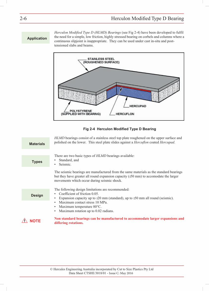
Herculon Modified Type D (HLMD) Bearings (see Fig 2-4) have been developed to fulfil the need for a simple, low friction, highly stressed bearing on corbels and columns where a continuous slipjoint is inappropriate. They can be used under cast in-situ and post-tensioned slabs and beams.
Fig 2-4 Herculon Modified Type D Bearing
Materials
HLMD bearings consist of a stainless steel top plate roughened on the upper surface and polished on the lower. This steel plate slides against a Hercuflon coated Hercupad.
Types
There are two basic types of HLMD bearings available:• Standard, and• Seismic.
The seismic bearings are manufactured from the same materials as the standard bearings but they have greater all round expansion capacity (±50 mm) to accomodate the larger movements which occur during seismic shock.
Design
The following design limitations are recommended:• Coefficient of friction 0.05.• Expansion capacity up to ±20 mm (standard), up to ±50 mm all round (seismic).• Maximum contact stress 10 MPa.• Maximum temperature 80°C.• Maximum rotation up to 0.02 radians.
NOTENon standard bearings can be manufactured to accommodate larger expansions and differing rotations.
© Hercules Engineering Australia incorporated by Cut to Size Plastics Pty LtdData Sheet CTSHE/3018/01 - Issue C: May 2016
Herculon Modified Type D Bearing 2-7Herculon Modified Type D Bearing 2-7
© Cut to Size Plastics Pty Ltd incorporating Hercules Engineering AustraliaData Sheet CTSHE/3018/00 - Issue A: November 2000
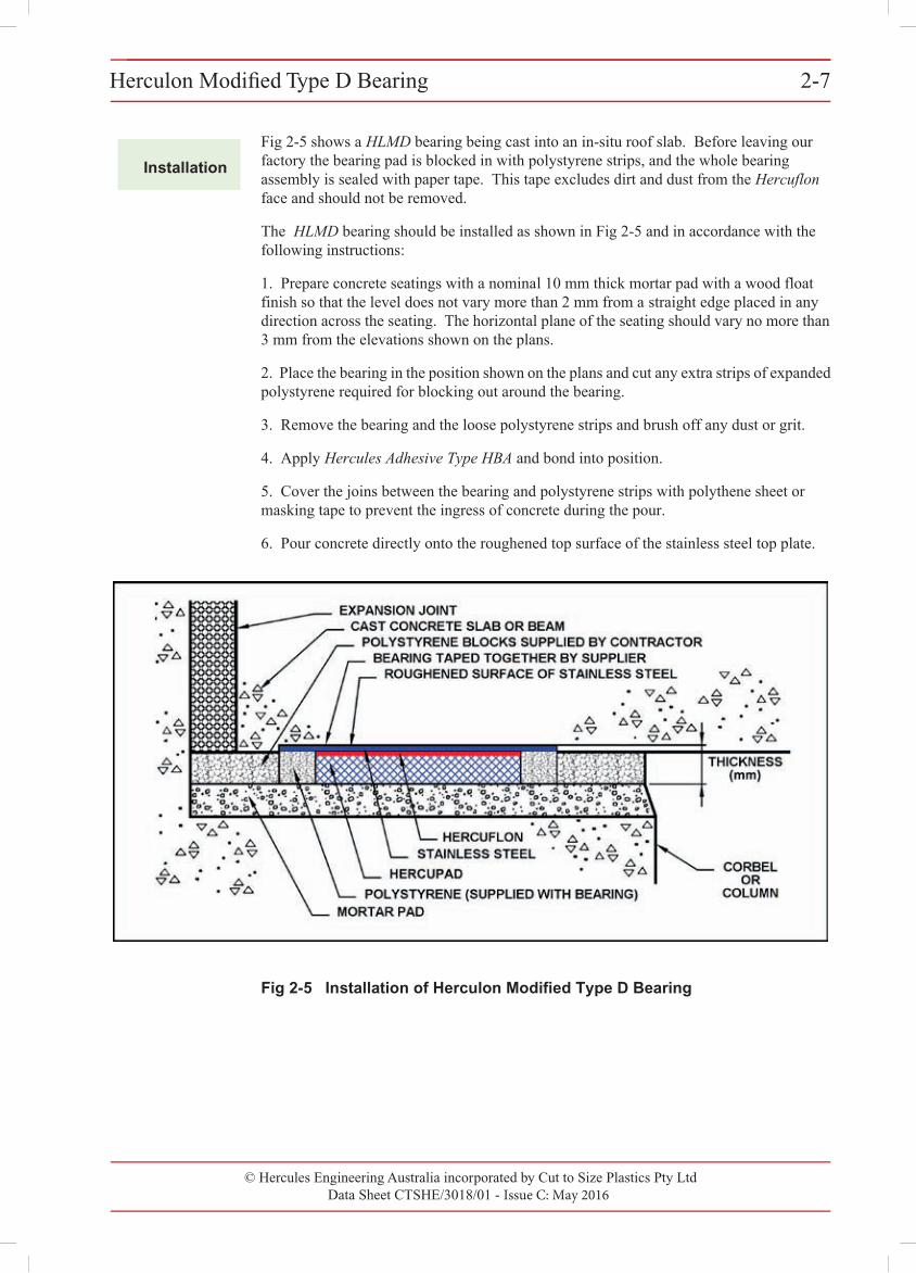
Installation
Fig 2-5 shows a HLMD bearing being cast into an in-situ roof slab. Before leaving our factory the bearing pad is blocked in with polystyrene strips, and the whole bearing assembly is sealed with paper tape. This tape excludes dirt and dust from the Hercuflon face and should not be removed.
The HLMD bearing should be installed as shown in Fig 2-5 and in accordance with the following instructions:
1. Prepare concrete seatings with a nominal 10 mm thick mortar pad with a wood floatfinish so that the level does not vary more than 2 mm from a straight edge placed in any direction across the seating. The horizontal plane of the seating should vary no more than 3 mm from the elevations shown on the plans.
2. Place the bearing in the position shown on the plans and cut any extra strips of expandedpolystyrene required for blocking out around the bearing.
3. Remove the bearing and the loose polystyrene strips and brush off any dust or grit.
4. Apply Hercules Adhesive Type HBA and bond into position.
5. Cover the joins between the bearing and polystyrene strips with polythene sheet ormasking tape to prevent the ingress of concrete during the pour.
6. Pour concrete directly onto the roughened top surface of the stainless steel top plate.
Fig 2-5 Installation of Herculon Modified Type D Bearing
2-8 Herculon Modified Type D Bearing
© Cut to Size Plastics Pty Ltd incorporating Hercules Engineering AustraliaData Sheet CTSHE/3018/00 - Issue A: November 2000
Ordering
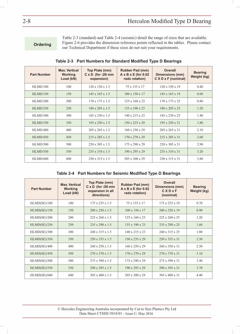
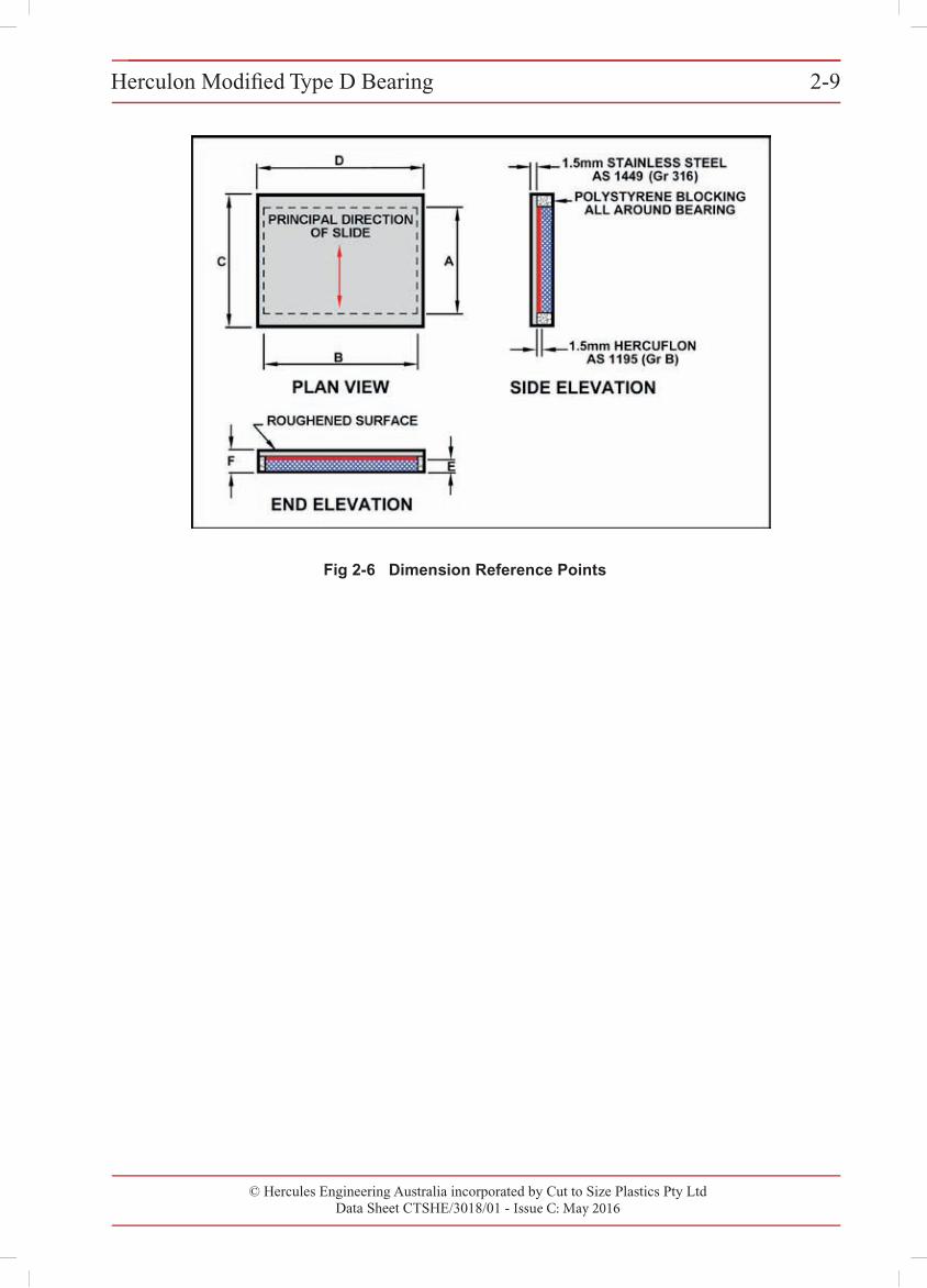
Table 2-3 (standard) and Table 2-4 (seismic) detail the range of sizes that are available. Figure 2-6 provides the dimension reference points reflected in the tables. Please contact our Technical Department if these sizes do not suit your requirements.
Table 2-3 Part Numbers for Standard Modified Type D Bearings
Part NumberMax. Vertical
Working Load (kN)
Top Plate (mm) C x D (for ±20 mm
expansion)
Rubber Pad (mm) A x B x E (for 0.02
rads rotation)
Overall Dimensions (mm)
C X D x F (nominal)
Bearing Weight (kg)
HLMD/100 100 120 x 150 x 1.5 75 x 135 x 17 120 x 150 x 19 0.40
HLMD/150 150 145 x 165 x 1.5 100 x 150 x 17 145 x 165 x 19 0.60
HLMD/200 200 170 x 175 x 1.5 125 x 160 x 23 170 x 175 x 25 0.80
HLMD/250 250 180 x 205 x 1.5 135 x 190 x 23 180 x 205 x 25 1.20
HLMD/300 300 185 x 230 x 1.5 140 x 215 x 23 185 x 230 x 25 1.40
HLMD/350 350 195 x 250 x 1.5 150 x 235 x 29 195 x 250 x 31 1.80
HLMD/400 400 205 x 265 x 1.5 160 x 250 x 29 205 x 265 x 31 2.10
HLMD/450 450 215 x 285 x 1.5 170 x 270 x 29 215 x 285 x 31 2.60
HLMD/500 500 220 x 305 x 1.5 175 x 290 x 29 220 x 305 x 31 2.90
HLMD/550 550 235 x 310 x 1.5 190 x 295 x 29 235 x 310 x 31 3.20
HLMD/600 600 250 x 315 x 1.5 205 x 300 x 29 250 x 315 x 31 3.80
Table 2-4 Part Numbers for Seismic Modified Type D Bearings
Part NumberMax. Vertical
Working Load (kN)
Top Plate (mm) C x D (for ±50 mm
expansion in all directions)
Rubber Pad (mm) A x B x E (for 0.02
rads rotation)
Overall Dimensions (mm)
C X D x F (nominal)
Bearing Weight (kg)
HLMD(SE)/100 100 175 x 235 x 1.5 75 x 135 x 17 175 x 235 x 19 0.70
HLMD(SE)/150 150 200 x 250 x 1.5 100 x 150 x 17 200 x 250 x 19 0.90
HLMD(SE)/200 200 225 x 260 x 1.5 125 x 160 x 23 225 x 260 x 25 1.20
HLMD(SE)/250 250 235 x 290 x 1.5 135 x 190 x 23 235 x 290 x 25 1.60
HLMD(SE)/300 300 240 x 315 x 1.5 140 x 215 x 23 240 x 315 x 25 1.80
HLMD(SE)/350 350 250 x 335 x 1.5 150 x 235 x 29 250 x 335 x 31 2.30
HLMD(SE)/400 400 260 x 250 x 1.5 160 x 250 x 29 260 x 350 x 31 2.50
HLMD(SE)/450 450 270 x 370 x 1.5 170 x 270 x 29 270 x 370 x 31 3.10
HLMD(SE)/500 500 275 x 390 x 1.5 175 x 290 x 29 275 x 390 x 31 3.40
HLMD(SE)/550 550 290 x 395 x 1.5 190 x 295 x 29 290 x 395 x 31 3.70
HLMD(SE)/600 600 305 x 400 x 1.5 205 x 300 x 29 305 x 400 x 31 4.40
© Hercules Engineering Australia incorporated by Cut to Size Plastics Pty LtdData Sheet CTSHE/3018/01 - Issue C: May 2016
Herculon Modified Type D Bearing2-8
© Hercules Engineering Australia incorporated by Cut to Size Plastics Pty Ltd Data Sheet CTSHE/3018/01 - Issue C: May 2016
Herculon Modified Type D Bearing 2-9Herculon Modified Type D Bearing 2-9
© Cut to Size Plastics Pty Ltd incorporating Hercules Engineering AustraliaData Sheet CTSHE/3018/00 - Issue A: November 2000
Fig 2-6 Dimension Reference Points

© Hercules Engineering Australia incorporated by Cut to Size Plastics Pty Ltd Issue C: May 2016
SECTION 3 - HERCULON TYPE D BEARINGS
Contents
Herculon Type D Free Float Bearing
Application 3-1
Materials 3-1
Design 3-1
Installation in Concrete Structures 3-4
Installation in Steel Structures 3-5
Ordering 3-6
Herculon Type D Sliding Guided Bearing
Application 3-7
Materials 3-7
Design 3-7
Installation in Concrete Structures 3-8
Installation in Steel Structures 3-9
Ordering 3-10
Herculon Type D Fixed Bearing
Application 3-14
Materials 3-14
Design 3-14
Installation in Concrete Structures 3-15
Installation in Steel Structures 3-16
Ordering 3-17
© Hercules Engineering Australia incorporated by Cut to Size Plastics Pty Ltd Issue C: May 2016
SECTION 3 - HERCULON TYPE D BEARINGS
Contents
Herculon Type D Tank Top Bearing
Application 3-21
Materials 3-21
Types 3-21
Design 3-21
Installation 3-22
Ordering 3-22
Herculon Type D Bearing Weights
Weight Range of Free Float Bearings 3-24
Weights of Sliding Guided/Fixed Bearings (Steel Structures) 3-24
Weights of Sliding Guided/Fixed Bearings 3-24(Concrete Structures)
Tank Top Bearing Weights 3-24
© Hercules Engineering Australia incorporated by Cut to Size Plastics Pty LtdData Sheet CTSHE/3010/01 - Issue C: May 2016
Herculon Type D Free Float Bearing 3-1Herculon Type D Free Float Bearing 3-1
© Cut to Size Plastics Pty Ltd incorporating Hercules Engineering AustraliaData Sheet CTSHE/3010/00 - Issue A: November 2000
3
Application
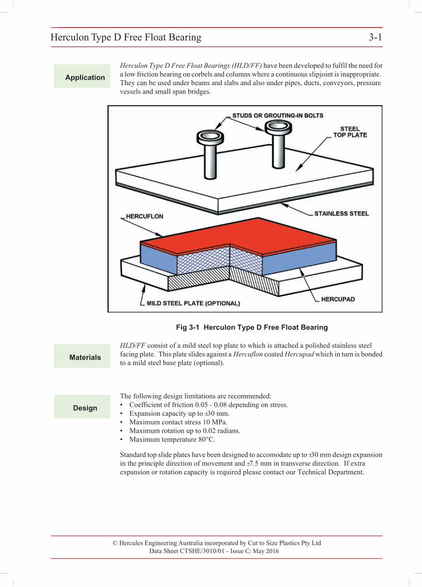
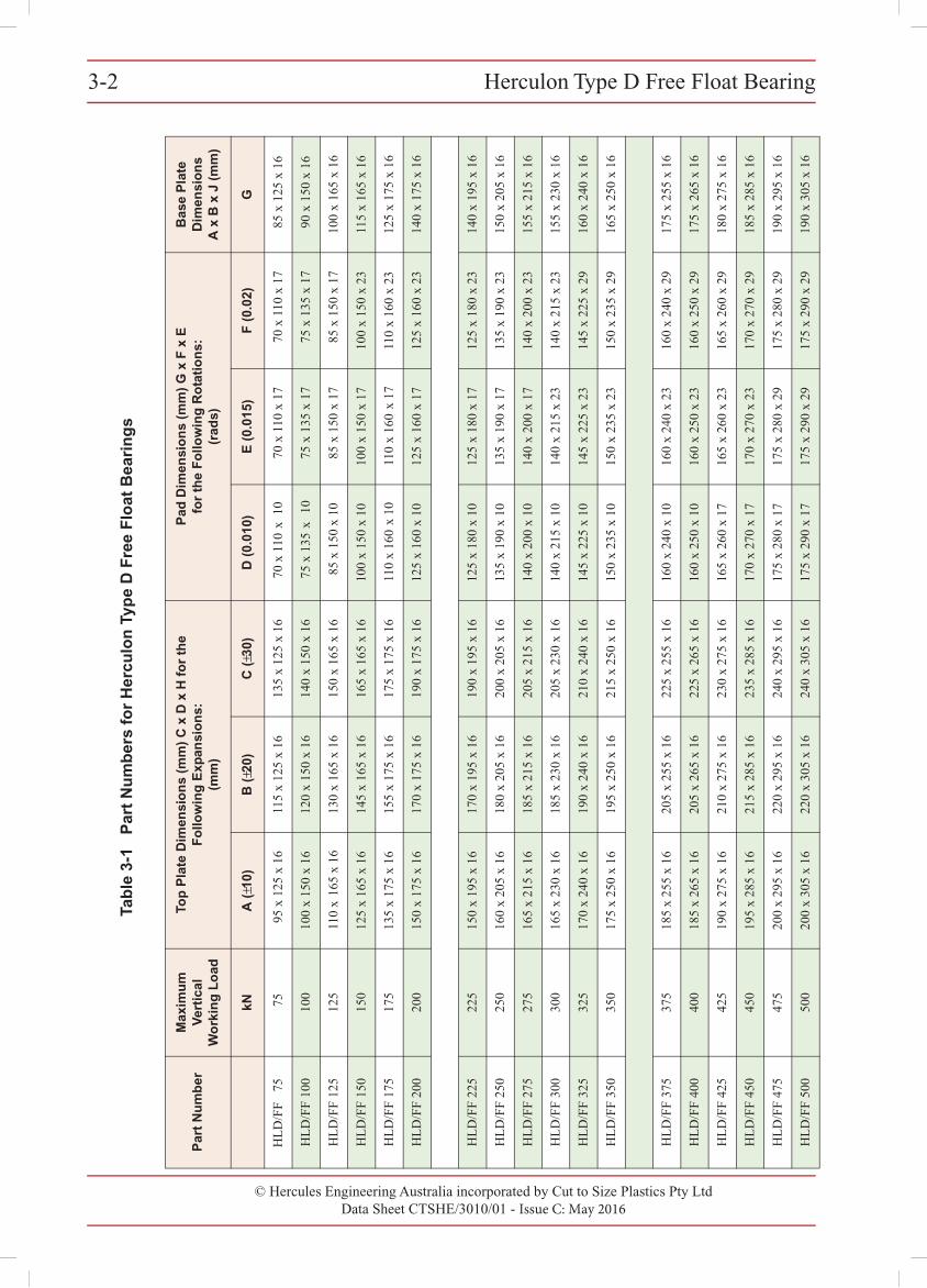
Herculon Type D Free Float Bearings (HLD/FF) have been developed to fulfil the need for a low friction bearing on corbels and columns where a continuous slipjoint is inappropriate. They can be used under beams and slabs and also under pipes, ducts, conveyors, pressure vessels and small span bridges.
Fig 3-1 Herculon Type D Free Float Bearing
Materials
HLD/FF consist of a mild steel top plate to which is attached a polished stainless steel facing plate. This plate slides against a Hercuflon coated Hercupad which in turn is bonded to a mild steel base plate (optional).
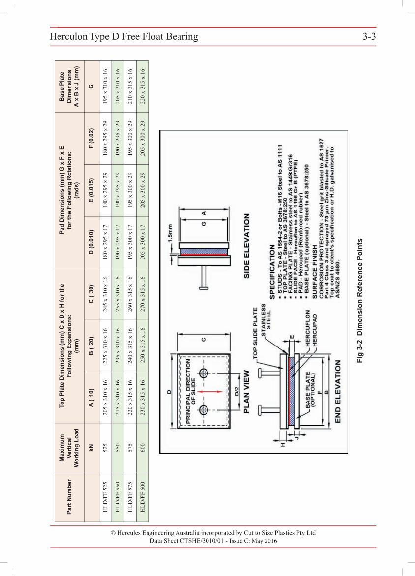
Design
The following design limitations are recommended:• Coefficient of friction 0.05 - 0.08 depending on stress.• Expansion capacity up to ±30 mm.• Maximum contact stress 10 MPa.• Maximum rotation up to 0.02 radians.• Maximum temperature 80°C.
Standard top slide plates have been designed to accomodate up to ±30 mm design expansion in the principle direction of movement and ±7.5 mm in transverse direction. If extra expansion or rotation capacity is required please contact our Technical Department.
© Hercules Engineering Australia incorporated by Cut to Size Plastics Pty LtdData Sheet CTSHE/3010/01 - Issue C: May 2016
Herculon Type D Free Float Bearing3-2 3-2 Herculon Type D Free Float Bearing
© Cut to Size Plastics Pty Ltd incorporating Hercules Engineering AustraliaData Sheet CTSHE/3010/00 - Issue A: November 2000
Tab
le 3
-1
Par
t N
um
ber
s fo
r H
ercu
lon
Typ
e D
Fre
e F
loat
Bea
rin
gs
Par
t N
um
ber
Max
imu
m
Ver
tica
l W
ork
ing
Lo
ad
Top
Pla
te D
imen
sio
ns
(mm
) C
x D
x H
fo
r th
e F
ollo
win
g E
xpan
sio
ns:
(mm
)
Pad
Dim
ensi
on
s (m
m)
G x
F x
E
for
the
Fo
llow
ing
Ro
tati
on
s:(r
ads)
Bas
e P
late
D
imen
sio
ns
A x
B x
J (
mm
)
kNA
(±1
0)B
(±2
0)C
(±3
0)D
(0.
010)
E (
0.01
5)F
(0.
02)
G
HLD
/FF
7575
95 x
125
x 1
611
5 x
125
x 16
135
x 12
5 x
1670
x 1
10 x
10
70 x
110
x 1
770
x 1
10 x
17
85 x
125
x 1
6
HLD
/FF
100
100
100
x 15
0 x
1612
0 x
150
x 16
140
x 15
0 x
1675
x 1
35 x
10
75 x
135
x 1
775
x 1
35 x
17
90 x
150
x 1
6
HLD
/FF
125
125
110
x 16
5 x
1613
0 x
165
x 16
150
x 16
5 x
1685
x 1
50 x
10
85 x
150
x 1
785
x 1
50 x
17
100
x 16
5 x
16
HLD
/FF
150
150
125
x 16
5 x
1614
5 x
165
x 16
165
x 16
5 x
1610
0 x
150
x 10
100
x 15
0 x
1710
0 x
150
x 23
115
x 16
5 x
16
HLD
/FF
175
175
135
x 17
5 x
1615
5 x
175
x 16
175
x 17
5 x
1611
0 x
160
x 10
110
x 16
0 x
1711
0 x
160
x 23
125
x 17
5 x
16
HLD
/FF
200
200
150
x 17
5 x
1617
0 x
175
x 16
190
x 17
5 x
1612
5 x
160
x 10
125
x 16
0 x
1712
5 x
160
x 23
140
x 17
5 x
16
HLD
/FF
225
225
150
x 19
5 x
1617
0 x
195
x 16
190
x 19
5 x
1612
5 x
180
x 10
125
x 18
0 x
1712
5 x
180
x 23
140
x 19
5 x
16
HLD
/FF
250
250
160
x 20
5 x
1618
0 x
205
x 16
200
x 20
5 x
1613
5 x
190
x 10
135
x 19
0 x
1713
5 x
190
x 23
150
x 20
5 x
16
HLD
/FF
275
275
165
x 21
5 x
1618
5 x
215
x 16
205
x 21
5 x
1614
0 x
200
x 10
140
x 20
0 x
1714
0 x
200
x 23
155
x 21
5 x
16
HLD
/FF
300
300
165
x 23
0 x
1618
5 x
230
x 16
205
x 23
0 x
1614
0 x
215
x 10
140
x 21
5 x
2314
0 x
215
x 23
155
x 23
0 x
16
HLD
/FF
325
325
170
x 24
0 x
1619
0 x
240
x 16
210
x 24
0 x
1614
5 x
225
x 10
145
x 22
5 x
2314
5 x
225
x 29
160
x 24
0 x
16
HLD
/FF
350
350
175
x 25
0 x
1619
5 x
250
x 16
215
x 25
0 x
1615
0 x
235
x 10
150
x 23
5 x
2315
0 x
235
x 29
165
x 25
0 x
16
HLD
/FF
375
375
185
x 25
5 x
1620
5 x
255
x 16
225
x 25
5 x
1616
0 x
240
x 10
160
x 24
0 x
2316
0 x
240
x 29
175
x 25
5 x
16
HLD
/FF
400
400
185
x 26
5 x
1620
5 x
265
x 16
225
x 26
5 x
1616
0 x
250
x 10
160
x 25
0 x
2316
0 x
250
x 29
175
x 26
5 x
16
HLD
/FF
425
425
190
x 27
5 x
1621
0 x
275
x 16
230
x 27
5 x
1616
5 x
260
x 17
165
x 26
0 x
2316
5 x
260
x 29
180
x 27
5 x
16
HLD
/FF
450
450
195
x 28
5 x
1621
5 x
285
x 16
235
x 28
5 x
1617
0 x
270
x 17
170
x 27
0 x
2317
0 x
270
x 29
185
x 28
5 x
16
HLD
/FF
475
475
200
x 29
5 x
1622
0 x
295
x 16
240
x 29
5 x
1617
5 x
280
x 17
175
x 28
0 x
2917
5 x
280
x 29
190
x 29
5 x
16
HLD
/FF
500
500
200
x 30
5 x
1622
0 x
305
x 16
240
x 30
5 x
1617
5 x
290
x 17
175
x 29
0 x
2917
5 x
290
x 29
190
x 30
5 x
16
© Hercules Engineering Australia incorporated by Cut to Size Plastics Pty LtdData Sheet CTSHE/3010/01 - Issue C: May 2016
Herculon Type D Free Float Bearing 3-3Herculon Type D Free Float Bearing 3-3
© Cut to Size Plastics Pty Ltd incorporating Hercules Engineering AustraliaData Sheet CTSHE/3010/00 - Issue A: November 2000
Fig
3-2
Dim
ensi
on
Ref
eren
ce P
oin
ts
HLD
/FF
525
525
205
x 31
0 x
1622
5 x
310
x 16
245
x 31
0 x
1618
0 x
295
x 17
180
x 29
5 x
2918
0 x
295
x 29
195
x 31
0 x
16
HLD
/FF
550
550
215
x 31
0 x
1623
5 x
310
x 16
255
x 31
0 x
1619
0 x
295
x 17
190
x 29
5 x
2919
0 x
295
x 29
205
x 31
0 x
16
HLD
/FF
575
575
220
x 31
5 x
1624
0 x
315
x 16
260
x 31
5 x
1619
5 x
300
x 17
195
x 30
0 x
2919
5 x
300
x 29
210
x 31
5 x
16
HLD
/FF
600
600
230
x 31
5 x
16 2
50 x
315
x 1
627
0 x
315
x 16
205
x 30
0 x
1720
5 x
300
x 29
205
x 30
0 x
2922
0 x
315
x 16
Par
t N
um
ber
Max
imu
m
Ver
tica
l W
ork
ing
Lo
ad
Top
Pla
te D
imen
sio
ns
(mm
) C
x D
x H
fo
r th
e F
ollo
win
g E
xpan
sio
ns:
(mm
)
Pad
Dim
ensi
on
s (m
m)
G x
F x
E
for
the
Fo
llow
ing
Ro
tati
on
s:(r
ads)
Bas
e P
late
D
imen
sio
ns
A x
B x
J (
mm
)
kNA
(±1
0)B
(±2
0)C
(±3
0)D
(0.
010)
E (
0.01
5)F
(0.
02)
G
© Hercules Engineering Australia incorporated by Cut to Size Plastics Pty LtdData Sheet CTSHE/3010/01 - Issue C: May 2016
Herculon Type D Free Float Bearing3-43-4 Herculon Type D Free Float Bearing
© Cut to Size Plastics Pty Ltd incorporating Hercules Engineering AustraliaData Sheet CTSHE/3010/00 - Issue A: November 2000
Installation
In Concrete Structures
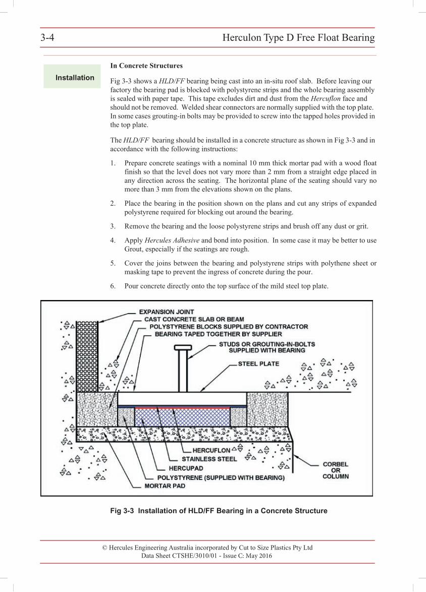
Fig 3-3 shows a HLD/FF bearing being cast into an in-situ roof slab. Before leaving our factory the bearing pad is blocked with polystyrene strips and the whole bearing assembly is sealed with paper tape. This tape excludes dirt and dust from the Hercuflon face and should not be removed. Welded shear connectors are normally supplied with the top plate. In some cases grouting-in bolts may be provided to screw into the tapped holes provided in the top plate.
The HLD/FF bearing should be installed in a concrete structure as shown in Fig 3-3 and in accordance with the following instructions:
1. Prepare concrete seatings with a nominal 10 mm thick mortar pad with a wood floatfinish so that the level does not vary more than 2 mm from a straight edge placed inany direction across the seating. The horizontal plane of the seating should vary nomore than 3 mm from the elevations shown on the plans.
2. Place the bearing in the position shown on the plans and cut any strips of expandedpolystyrene required for blocking out around the bearing.
3. Remove the bearing and the loose polystyrene strips and brush off any dust or grit.
4. Apply Hercules Adhesive and bond into position. In some case it may be better to useGrout, especially if the seatings are rough.
5. Cover the joins between the bearing and polystyrene strips with polythene sheet ormasking tape to prevent the ingress of concrete during the pour.
6. Pour concrete directly onto the top surface of the mild steel top plate.
Fig 3-3 Installation of HLD/FF Bearing in a Concrete Structure
© Hercules Engineering Australia incorporated by Cut to Size Plastics Pty LtdData Sheet CTSHE/3010/01 - Issue C: May 2016
Herculon Type D Free Float Bearing 3-5Herculon Type D Free Float Bearing 3-5
© Cut to Size Plastics Pty Ltd incorporating Hercules Engineering AustraliaData Sheet CTSHE/3010/00 - Issue A: November 2000
Installation
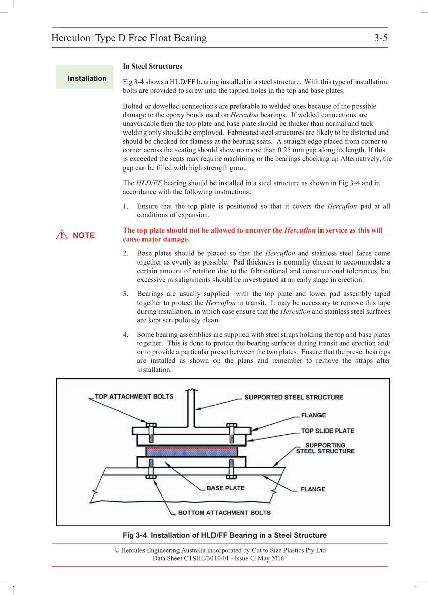
In Steel Structures
Fig 3-4 shows a HLD/FF bearing installed in a steel structure. With this type of installation, bolts are provided to screw into the tapped holes in the top and base plates.
Bolted or dowelled connections are preferable to welded ones because of the possible damage to the epoxy bonds used on Herculon bearings. If welded connections are unavoidable then the top plate and base plate should be thicker than normal and tack welding only should be employed. Fabricated steel structures are likely to be distorted and should be checked for flatness at the bearing seats. A straight edge placed from corner to corner across the seating should show more than 0.25 mm gap along its length. If this
exceeded the seats may require machining or the bearings chocking up Alternatively, the gap can be filled with high strength grout.
The HLD/FF bearing should be installed in a steel structure as shown in Fig 3-4 and in accordance with the following instructions:
1. Ensure that the top plate is positioned so that it covers the Hercuflon pad at allconditions of expansion.
no
NOTEThe top plate should not be allowed to uncover the Hercuflon in service as this will cause major damage.
2. Base plates should be placed so that the Hercuflon and stainless steel faces come together as evenly as possible. Pad thickness is normally chosen to accommodate a certain amount of rotation due to the fabricational and constructional tolerances, butexcessive misalignments should be investigated at an early stage in erection.
3. Bearings are usually supplied with the top plate and lower pad assembly taped together to protect the Hercuflon in transit. It may be necessary to remove this tape during installation, in which case ensure that the Hercuflon and stainless steel surfacesare kept scrupulously clean.
4. Some bearing assemblies are supplied with steel straps holding the top and base plates together. This is done to protect the bearing surfaces during transit and erection and/or to provide a particular preset between the two plates. Ensure that the preset bearings are installed as shown on the plans and remember to remove the straps afterinstallation.
Fig 3-4 Installation of HLD/FF Bearing in a Steel Structure
Herculon Type D Free Float Bearing 3-5
© Cut to Size Plastics Pty Ltd incorporating Hercules Engineering AustraliaData Sheet CTSHE/3010/00 - Issue A: November 2000
Installation
In Steel Structures
Fig 3-4 shows a HLD/FF bearing installed in a steel structure. With this type of installation, bolts are provided to screw into the tapped holes in the top and base plates.
Bolted or dowelled connections are preferable to welded ones because of the possibledamage to the epoxy bonds used on Herculon bearings. If welded connections are unavoidable then the top plate and base plate should be thicker than normal and tackwelding only should be employed. Fabricated steel structures are likely to be distorted and should be checked for flatness at the bearing seats. A straight edge placed from corner tocorner across the seating should show more than 0.25 mm gap along its length. If this is exceeded the seats may require machining or the bearings chocking up. Alternatively, thegap can be filled with high strength grout.
The HLD/FF bearing should be installed in a steel structure as shown in Fig 3-4 and inaccordance with the following instructions:
1. Ensure that the top plate is positioned so that it covers the Hercuflon pad at all conditions of expansion.
NOTEThe top plate should not be allowed to uncover the Hercuflon in service as this will cause major damage.
2. Base plates should be placed so that the Hercuflon and stainless steel faces come together as evenly as possible. Pad thickness is normally chosen to accommodate a certain amount of rotation due to the fabricational and constructional tolerances, but excessive misalignments should be investigated at an early stage in erection.
3. Bearings are usually supplied with the top plate and lower pad assembly taped together to protect the Hercuflon in transit. It may be necessary to remove this tape during installation, in which case ensure that the Hercuflon and stainless steel surfaces are kept scrupulously clean.
4. Some bearing assemblies are supplied with steel straps holding the top and base platestogether. This is done to protect the bearing surfaces during transit and erection and/or to provide a particular preset between the two plates. Ensure that the preset bearings are installed as shown on the plans and remember to remove the straps after installation.
Fig 3-4 Installation of HLD/FF Bearing in a Steel Structure
Herculon Type D Free Float Bearing 3-5
© Cut to Size Plastics Pty Ltd incorporating Hercules Engineering AustraliaData Sheet CTSHE/3010/00 - Issue A: November 2000
Installation
In Steel Structures
Fig 3-4 shows a HLD/FF bearing installed in a steel structure. With this type of installation, bolts are provided to screw into the tapped holes in the top and base plates.
Bolted or dowelled connections are preferable to welded ones because of the possibledamage to the epoxy bonds used on Herculon bearings. If welded connections are unavoidable then the top plate and base plate should be thicker than normal and tackwelding only should be employed. Fabricated steel structures are likely to be distorted and should be checked for flatness at the bearing seats. A straight edge placed from corner tocorner across the seating should show more than 0.25 mm gap along its length. If this is exceeded the seats may require machi ing or the bearings chocking up. Alternatively, thegap can be filled with high strength grout.
The HLD/FF bearing should be installed in a steel structure as shown in Fig 3-4 and inaccordance with the following instructions:
1. Ensure that the top plate is positioned so that it covers the Hercuflon pad at all conditions of expansion.
NOTEThe top plate should not be allowed to uncover the Hercuflon in service as this will cause major damage.
2. Base plates should be placed so that the Hercuflon and stainless steel faces come together as evenly as possible. Pad thickness is normally chosen to accommodate a certain amount of rotation due to the fabricational and constructional tolerances, but excessive misalignments should be investigated at an early stage in erection.
3. Bearings are usually supplied with the top plate and lower pad assembly taped together to protect the Hercuflon in transit. It may be necessary to remove this tape during installation, in which case ensure that the Hercuflon and stainless steel surfaces are kept scrupulously clean.
4. Some bearing assemblies are supplied with steel straps holding the top and base platestogether. This is done to protect the bearing surfaces during transit and erection and/or to provide a particular preset between the two plates. Ensure that the preset bearings are installed as shown on the plans and remember to remove the straps after installation.
Fig 3-4 Installation of HLD/FF Bearing in a Steel Structure
is
© Hercules Engineering Australia incorporated by Cut to Size Plastics Pty LtdData Sheet CTSHE/3010/01 - Issue C: May 2016
Herculon Type D Free Float Bearing3-63-6 Herculon Type D Free Float Bearing
© Cut to Size Plastics Pty Ltd incorporating Hercules Engineering AustraliaData Sheet CTSHE/3010/00 - Issue A: November 2000
Ordering
The part number is made up of groups of letters and numbers - HLD/FF/175/A/E/G . This part number equates to:
HLD - Herculon Type D
FF - Free Float
175 - Capacity in kN
A - Expansion capacity
E - Rotational capacity
G - Base plate (optional)
© Hercules Engineering Australia incorporated by Cut to Size Plastics Pty Ltd Data Sheet CTSHE/3010/01 - Issue C: May 2016
Herculon Type D Sliding Guided Bearing 3-7Herculon Type D Sliding Guided Bearing 3-7
© Cut to Size Plastics Pty Ltd incorporating Hercules Engineering AustraliaData Sheet CTSHE/3010/00 - Issue A: November 2000
3
Application
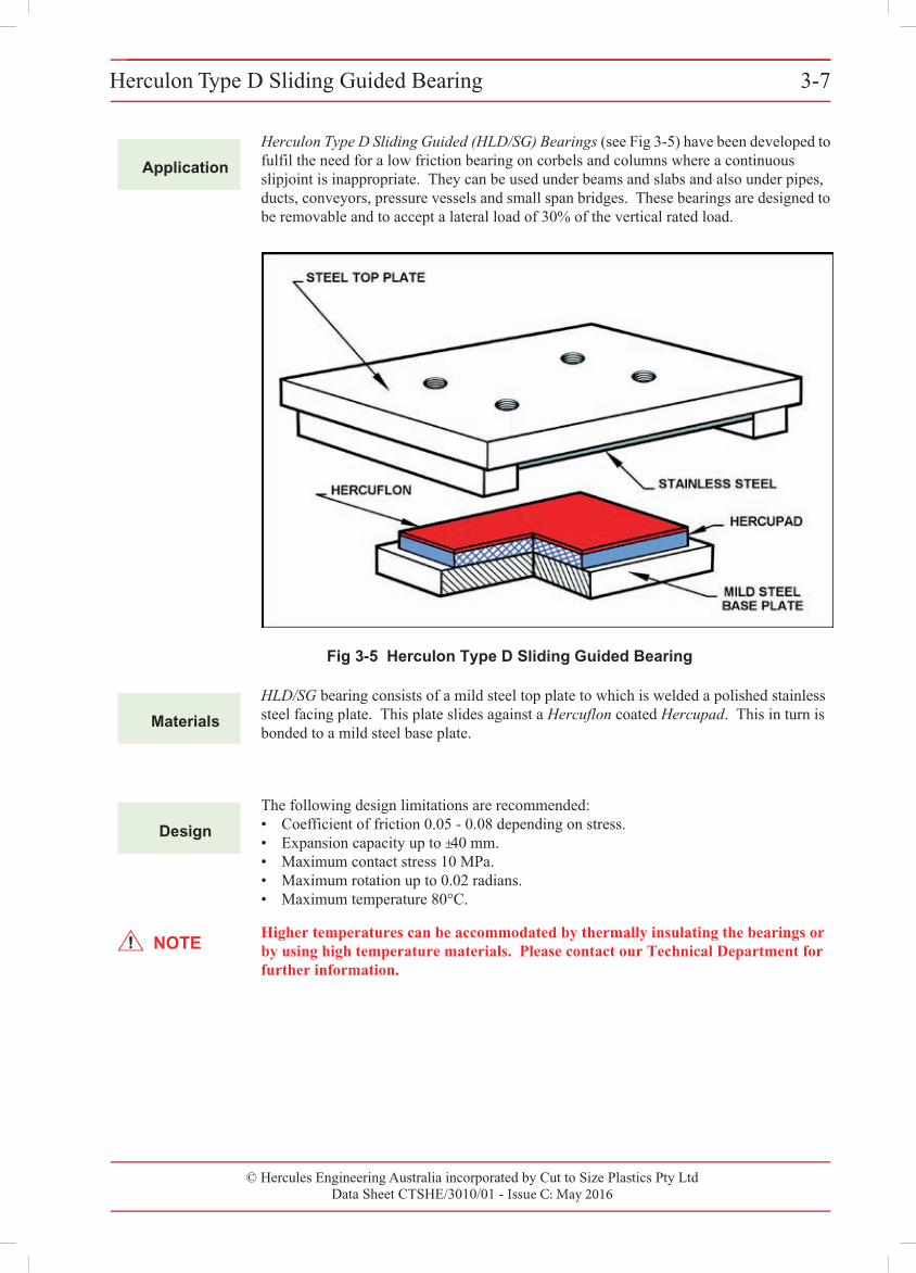
Herculon Type D Sliding Guided (HLD/SG) Bearings (see Fig 3-5) have been developed to fulfil the need for a low friction bearing on corbels and columns where a continuous slipjoint is inappropriate. They can be used under beams and slabs and also under pipes, ducts, conveyors, pressure vessels and small span bridges. These bearings are designed to be removable and to accept a lateral load of 30% of the vertical rated load.
Fig 3-5 Herculon Type D Sliding Guided Bearing
Materials
HLD/SG bearing consists of a mild steel top plate to which is welded a polished stainless steel facing plate. This plate slides against a Hercuflon coated Hercupad. This in turn is bonded to a mild steel base plate.
Design
The following design limitations are recommended:• Coefficient of friction 0.05 - 0.08 depending on stress.• Expansion capacity up to ±40 mm.• Maximum contact stress 10 MPa.• Maximum rotation up to 0.02 radians.• Maximum temperature 80°C.
NOTEHigher temperatures can be accommodated by thermally insulating the bearings or by using high temperature materials. Please contact our Technical Department for further information.
© Hercules Engineering Australia incorporated by Cut to Size Plastics Pty LtdData Sheet CTSHE/3010/01 - Issue C: May 2016
Herculon Type D Sliding Guided Bearing3-83-8 Herculon Type D Sliding Guided Bearing
© Cut to Size Plastics Pty Ltd incorporating Hercules Engineering AustraliaData Sheet CTSHE/3010/00 - Issue A: November 2000
Installation
In Concrete Structures
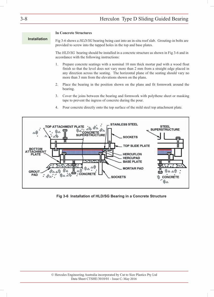
Fig 3-6 shows a HLD/SG bearing being cast into an in-situ roof slab. Grouting-in bolts are provided to screw into the tapped holes in the top and base plates.
The HLD/SG bearing should be installed in a concrete structure as shown in Fig 3-6 and in accordance with the following instructions:
1. Prepare concrete seatings with a nominal 10 mm thick mortar pad with a wood floatfinish so that the level does not vary more than 2 mm from a straight edge placed inany direction across the seating. The horizontal plane of the seating should vary nomore than 3 mm from the elevations shown on the plans.
2. Place the bearing in the position shown on the plans and fit formwork around thebearing.
3. Cover the joins between the bearing and formwork with polythene sheet or maskingtape to prevent the ingress of concrete during the pour.
4. Pour concrete directly onto the top surface of the mild steel top attachment plate.
Fig 3-6 Installation of HLD/SG Bearing in a Concrete Structure
© Hercules Engineering Australia incorporated by Cut to Size Plastics Pty LtdData Sheet CTSHE/3010/01 - Issue C: May 2016
Herculon Type D Sliding Guided Bearing 3-9Herculon Type D Sliding Guided Bearing 3-9
© Cut to Size Plastics Pty Ltd incorporating Hercules Engineering AustraliaData Sheet CTSHE/3010/00 - Issue A: November 2000
Installation
In Steel Structures
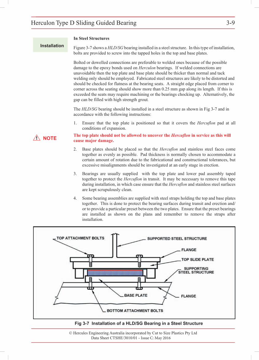
Figure 3-7 shows a HLD/SG bearing installed in a steel structure. In this type of installation, bolts are provided to screw into the tapped holes in the top and base plates.
Bolted or dowelled connections are preferable to welded ones because of the possible damage to the epoxy bonds used on Herculon bearings. If welded connections are unavoidable then the top plate and base plate should be thicker than normal and tack welding only should be employed. Fabricated steel structures are likely to be distorted and should be checked for flatness at the bearing seats. A straight edge placed from corner to corner across the seating should show more than 0.25 mm gap along its length. If this is exceeded the seats may require machining or the bearings chocking up. Alternatively, the gap can be filled with high strength grout.
The HLD/SG bearing should be installed in a steel structure as shown in Fig 3-7 and in accordance with the following instructions:
1. Ensure that the top plate is positioned so that it covers the Hercuflon pad at allconditions of expansion.
NOTEThe top plate should not be allowed to uncover the Hercuflon in service as this will cause major damage.
2. Base plates should be placed so that the Hercuflon and stainless steel faces come together as evenly as possible. Pad thickness is normally chosen to accommodate a certain amount of rotation due to the fabricational and constructional tolerances, but excessive misalignments should be investigated at an early stage in erection.
3. Bearings are usually supplied with the top plate and lower pad assembly taped together to protect the Hercuflon in transit. It may be necessary to remove this tape during installation, in which case ensure that the Hercuflon and stainless steel surfacesare kept scrupulously clean.
4. Some bearing assemblies are supplied with steel straps holding the top and base platestogether. This is done to protect the bearing surfaces during transit and erection and/or to provide a particular preset between the two plates. Ensure that the preset bearings are installed as shown on the plans and remember to remove the straps after installation.
Fig 3-7 Installation of a HLD/SG Bearing in a Steel Structure
Herculon Type D Sliding Guided Bearing 3-9
© Cut to Size Plastics Pty Ltd incorporating Hercules Engineering AustraliaData Sheet CTSHE/3010/00 - Issue A: November 2000
Installation
In Steel Structures
Figure 3-7 shows a HLD/SG bearing installed in a steel structure. In this type of installation, bolts are provided to screw into the tapped holes in the top and base plates.
Bolted or dowelled connections are preferable to welded ones because of the possibledamage to the epoxy bonds used on Herculon bearings. If welded connections areunavoidable then the top plate and base plate should be thicker than normal and tackwelding only should be employed. Fabricated steel structures are likely to be distorted and should be checked for flatness at the bearing seats. A straight edge placed from corner tocorner across the seating should show more than 0.25 mm gap along its length. If this is exceeded the seats may require machining or the bearings chocking up. Alternatively, thegap can be filled with high strength grout.
The HLD/SG bearing should be installed in a steel structure as shown in Fig 3-7 and inaccordance with the following instructions:
1. Ensure that the top plate is positioned so that it covers the Hercuflon pad at allconditions of expansion.
NOTEThe top plate should not be allowed to uncover the Hercuflon in service as this will cause major damage.
2. Base plates should be placed so that the Hercuflon and stainless steel faces come together as evenly as possible. Pad thickness is normally chosen to accommodate a certain amount of rotation due to the fabricational and constructional tolerances, butexcessive misalignments should be investigated at an early stage in erection.
3. Bearings are usually supplied with the top plate and lower pad assembly taped together to protect the Hercuflon in transit. It may be necessary to remove this tape during installation, in which case ensure that the Hercuflon and stainless steel surfaces are kept scrupulously clean.
4. Some bearing assemblies are supplied with steel straps holding the top and base platestogether. This is done to protect the bearing surfaces during transit and erection and/or to provide a particular preset between the two plates. Ensure that the preset bearingsare installed as shown on the plans and remember to remove the straps afterinstallation.
Fig 3-7 Installation of a HLD/SG Bearing in a Steel Structure
Herculon Type D Sliding Guided Bearing 3-9
© Cut to Size Plastics Pty Ltd incorporating Hercules Engineering AustraliaData Sheet CTSHE/3010/00 - Issue A: November 2000
Installation
In Steel Structures
Figure 3-7 shows a HLD/SG bearing installed in a steel structure. In this type of installation, bolts are provided to screw into the tapped holes in the top and base plates.
Bolted or dowelled connections are preferable to welded ones because of the possibledamage to the epoxy bonds used on Herculon bearings. If welded connections areunavoidable then the top plate and base plate should be thicker than normal and tackwelding only should be employed. Fabricated steel structures are likely to be distorted and should be checked for flatness at the bearing seats. A straight edge placed from corner tocorner across the seating should show more than 0.25 mm gap along its length. If this is exceeded the seats may require machining or the bearings chocking up. Alternatively, thegap can be filled with high strength grout.
The HLD/SG bearing should be installed in a steel structure as shown in Fig 3-7 and inaccordance with the following instructions:
1. Ensure that the top plate is positioned so that it covers the Hercuflon pad at allconditions of expansion.
NOTEThe top plate should not be allowed to uncover the Hercuflon in service as this will cause major damage.
2. Base plates should be placed so that the Hercuflon and stainless steel faces come together as evenly as possible. Pad thickness is normally chosen to accommodate a certain amount of rotation due to the fabricational and constructional tolerances, but excessive misalignments should be investigated at an early stage in erection.
3. Bearings are usually supplied with the top plate and lower pad assembly taped together to protect the Hercuflon in transit. It may be necessary to remove this tape during installation, in which case ensure that the Hercuflon and stainless steel surfacesare kept scrupulously clean.
4. Some bearing assemblies are supplied with steel straps holding the top and base platestogether. This is done to protect the bearing surfaces during transit and erection and/or to provide a particular preset between the two plates. Ensure that the preset bearings are installed as shown on the plans and remember to remove the straps after installation.
Fig 3-7 Installation of a HLD/SG Bearing in a Steel Structure
Herculon Type D Sliding Guided Bearing 3-9
© Cut to Size Plastics Pty Ltd incorporating Hercules Engineering AustraliaData Sheet CTSHE/3010/00 - Issue A: November 2000
Installation
In Steel Structures
Figure 3-7 shows a HLD/SG bearing installed in a steel structure. In this type of installation, bolts are provided to screw into the tapped holes in the top and base plates.
Bolted or dowelled connections are preferable to welded ones because of the possibledamage to the epoxy bonds used on Herculon bearings. If welded connections areunavoidable then the top plate and base plate should be thicker than normal and tackwelding only should be employed. Fabricated steel structures are likely to be distorted and should be checked for flatness at the bearing seats. A straight edge placed from corner tocorner across the seating should show more than 0.25 mm gap along its length. If this is exceeded the seats may require machining or the bearings chocking up. Alternatively, thegap can be filled with high strength grout.
The HLD/SG bearing should be installed in a steel structure as shown in Fig 3-7 and inaccordance with the following instructions:
1. Ensure that the top plate is positioned so that it covers the Hercuflon pad at allconditions of expansion.
NOTEThe top plate should not be allowed to uncover the Hercuflon in service as this will cause major damage.
2. Base plates should be placed so that the Hercuflon and stainless steel faces come together as evenly as possible. Pad thickness is normally chosen to accommodate a certain amount of rotation due to the fabricational and constructional tolerances, but excessive misalignments should be investigated at an early stage in erection.
3. Bearings are usually supplied with the top plate and lower pad assembly taped together to protect the Hercuflon in transit. It may be necessary to remove this tape during installation, in which case ensure that the Hercuflon and stainless steel surfacesare kept scrupulously clean.
4. Some bearing assemblies are supplied with steel straps holding the top and base platestogether. This is done to protect the bearing surfaces during transit and erection and/or to provide a particular preset between the two plates. Ensure that the preset bearings are installed as shown on the plans and remember to remove the straps after installation.
Fig 3-7 Installation of a HLD/SG Bearing in a Steel Structure
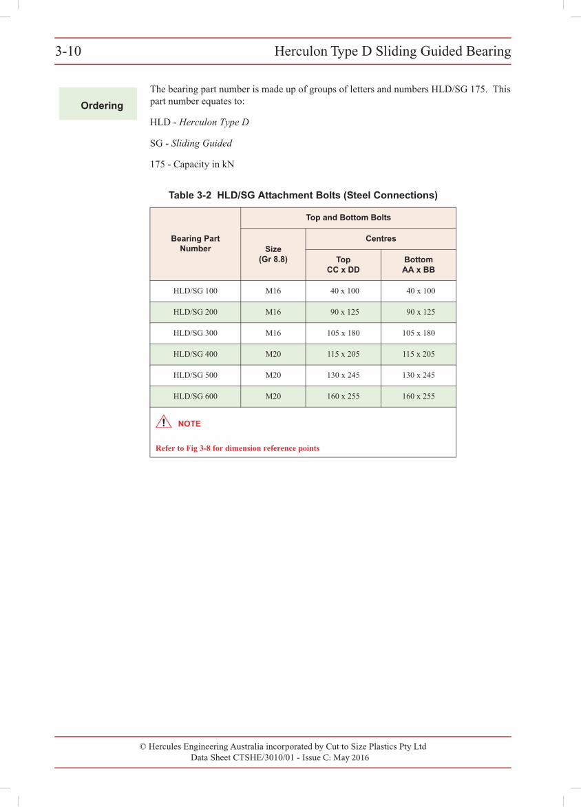
3-10 Herculon Type D Sliding Guided Bearing
© Cut to Size Plastics Pty Ltd incorporating Hercules Engineering AustraliaData Sheet CTSHE/3010/00 - Issue A: November 2000
Ordering
The bearing part number is made up of groups of letters and numbers HLD/SG 175. This part number equates to:
HLD - Herculon Type D
SG - Sliding Guided
175 - Capacity in kN
Table 3-2 HLD/SG Attachment Bolts (Steel Connections)
Bearing Part Number
Top and Bottom Bolts
Size (Gr 8.8)
Centres
TopCC x DD
BottomAA x BB
HLD/SG 100 M16 40 x 100 40 x 100
HLD/SG 200 M16 90 x 125 90 x 125
HLD/SG 300 M16 105 x 180 105 x 180
HLD/SG 400 M20 115 x 205 115 x 205
HLD/SG 500 M20 130 x 245 130 x 245
HLD/SG 600 M20 160 x 255 160 x 255
Refer to Fig 3-8 for dimension reference points
NOTE
© Hercules Engineering Australia incorporated by Cut to Size Plastics Pty LtdData Sheet CTSHE/3010/01 - Issue C: May 2016
Herculon Type D Sliding Guided Bearing3-10
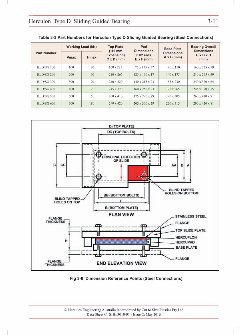
Table 3-3 Part Numbers for Herculon Type D Sliding Guided Bearing (Steel Connections)
Part Number
Working Load (kN) Top Plate (±40 mm
Expansion) C x D (mm)
Pad Dimensions
0.02 rads E x F (mm)
Base Plate DimensionsA x B (mm)
Bearing Overall Dimensions
C x D x H(mm)Vmax Hmax
HLD/SG 100 100 30 160 x 225 75 x 135 x 17 90 x 150 160 x 225 x 59
HLD/SG 200 200 60 210 x 265 125 x 160 x 17 140 x 175 210 x 265 x 59
HLD/SG 300 300 90 240 x 320 140 x 215 x 23 155 x 230 240 x 320 x 65
HLD/SG 400 400 120 245 x 370 160 x 250 x 23 175 x 265 245 x 370 x 75
HLD/SG 500 500 150 260 x 410 175 x 290 x 29 190 x 305 260 x 410 x 81
HLD/SG 600 600 180 290 x 420 205 x 300 x 29 220 x 315 290 x 420 x 81
Herculon Type D Sliding Guided Bearing 3-11
© Cut to Size Plastics Pty Ltd incorporating Hercules Engineering AustraliaData Sheet CTSHE/3010/00 - Issue A: November 2000
Fig 3-8 Dimension Reference Points (Steel Connections)
© Hercules Engineering Australia incorporated by Cut to Size Plastics Pty LtdData Sheet CTSHE/3010/01 - Issue C: May 2016
Herculon Type D Sliding Guided Bearing 3-11
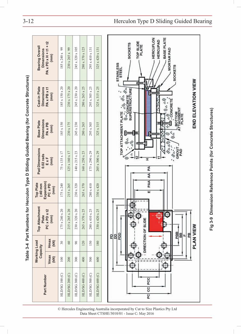
© Hercules Engineering Australia incorporated by Cut to Size Plastics Pty LtdData Sheet CTSHE/3010/01 - Issue C: May 2016
Herculon Type D Sliding Guided Bearing3-12 T
able
3-4
Par
t N
um
ber
s fo
r H
ercu
lon
Typ
e D
Slid
ing
Gu
ided
Bea
rin
g (
for
Co
ncr
ete
Str
uct
ure
s)
Par
t N
um
ber
Wo
rkin
g L
oad
C
apac
ity
Top
Att
ach
men
t P
late
P
C x
PD
x t
2 (m
m)
Top
Pla
te
(±40
mm
E
xpan
sio
n)
PC
x P
D
(mm
)
Pad
Dim
ensi
on
s 0.
02 r
ads
E x
F(m
m)
Bas
e P
late
D
imen
sio
ns
PA
x P
B(m
m)
Cas
t-in
Pla
te
Dim
ensi
on
sP
A x
PB
x t
1(m
m)
Bea
rin
g O
vera
ll D
imen
sio
ns
PA
x P
D x
H +
t1
+ t
2(m
m)
Vm
ax
(kN
)H
max
(k
N)
HLD
/SG
100
(C)
100
3017
5 x
240
x 20
175
x 24
075
x 1
35 x
17
185
x 15
018
5 x
150
x 20
185
x 24
0 x
99
HLD
/SG
200
(C)
200
6021
5 x
265
x 20
215
x 26
512
5 x
160
x 17
230
x 17
523
0 x
175
x 20
230
x 26
5 x
99
HLD
/SG
300
(C)
300
9023
0 x
320
x 20
230
x 32
014
0 x
215
x 23
245
x 23
024
5 x
230
x 20
245
x 32
0 x
105
HLD
/SG
400
(C)
400
120
265
x 37
0 x
2526
5 x
370
160
x 25
0 x
2328
0 x
265
280
x 26
5 x
2528
0 x
370
x 12
5
HLD
/SG
500
(C)
500
150
280
x 41
0 x
2528
0 x
410
175
x 29
0 x
2929
5 x
305
295
x 30
5 x
2529
5 x
410
x 13
1
HLD
/SG
600
(C)
600
180
330
x 42
0 x
2533
0 x
420
205
x 30
0 x
2932
5 x
315
325
x 31
5 x
2532
5 x
420
x 13
1
3-12 Herculon Type D Sliding Guided Bearing
© Cut to Size Plastics Pty Ltd incorporating Hercules Engineering AustraliaData Sheet CTSHE/3010/00 - Issue A: November 2000
Fig
3-9
Dim
ensi
on
Ref
eren
ce P
oin
ts (
for
Co
ncr
ete
Str
uct
ure
s)
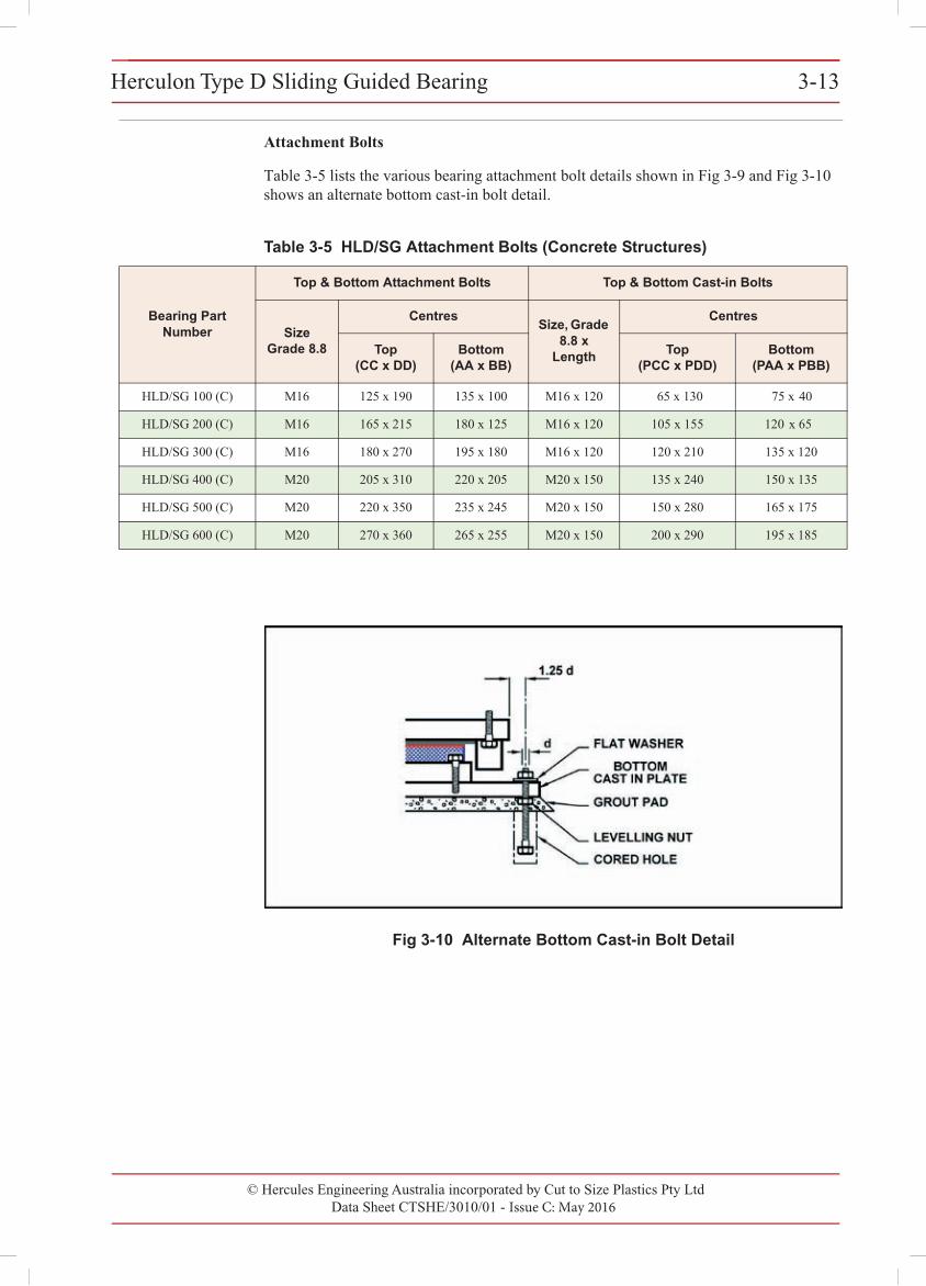
© Hercules Engineering Australia incorporated by Cut to Size Plastics Pty LtdData Sheet CTSHE/3010/01 - Issue C: May 2016
Herculon Type D Sliding Guided Bearing 3-13Herculon Type D Sliding Guided Bearing 3-13
© Cut to Size Plastics Pty Ltd incorporating Hercules Engineering AustraliaData Sheet CTSHE/3010/00 - Issue A: November 2000
Attachment Bolts
Table 3-5 lists the various bearing attachment bolt details shown in Fig 3-9 and Fig 3-10 shows an alternate bottom cast-in bolt detail.
Table 3-5 HLD/SG Attachment Bolts (Concrete Structures)
Bearing Part Number
Top & Bottom Attachment Bolts Top & Bottom Cast-in Bolts
Size Grade 8.8
CentresSize, Grade
8.8 x Length
Centres
Top (CC x DD)
Bottom(AA x BB)
Top (PCC x PDD)
Bottom (PAA x PBB)
HLD/SG 100 (C) M16 125 x 190 135 x 100 M16 x 120 65 x 130 75 x 40
HLD/SG 200 (C) M16 165 x 215 180 x 125 M16 x 120 105 x 155 120 x 65
HLD/SG 300 (C) M16 180 x 270 195 x 180 M16 x 120 120 x 210 135 x 120
HLD/SG 400 (C) M20 205 x 310 220 x 205 M20 x 150 135 x 240 150 x 135
HLD/SG 500 (C) M20 220 x 350 235 x 245 M20 x 150 150 x 280 165 x 175
HLD/SG 600 (C) M20 270 x 360 265 x 255 M20 x 150 200 x 290 195 x 185
Fig 3-10 Alternate Bottom Cast-in Bolt Detail
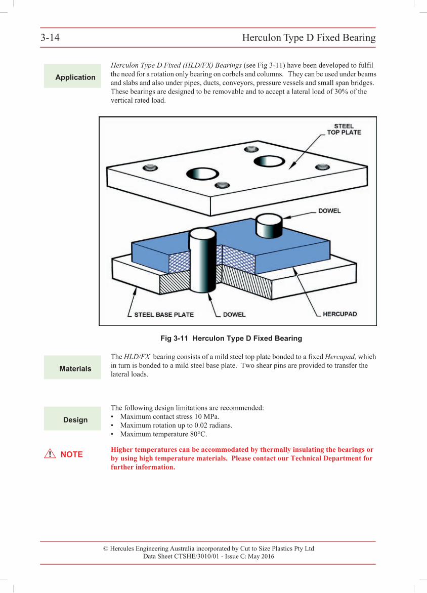
© Hercules Engineering Australia incorporated by Cut to Size Plastics Pty Ltd Data Sheet CTSHE/3010/01 - Issue C: May 2016
Herculon Type D Fixed Bearing3-143-14 Herculon Type D Fixed Bearing
© Cut to Size Plastics Pty Ltd incorporating Hercules Engineering AustraliaData Sheet CTSHE/3010/00 - Issue A: November 2000
3
Application
Herculon Type D Fixed (HLD/FX) Bearings (see Fig 3-11) have been developed to fulfil the need for a rotation only bearing on corbels and columns. They can be used under beams and slabs and also under pipes, ducts, conveyors, pressure vessels and small span bridges. These bearings are designed to be removable and to accept a lateral load of 30% of the vertical rated load.
Fig 3-11 Herculon Type D Fixed Bearing
Materials
The HLD/FX bearing consists of a mild steel top plate bonded to a fixed Hercupad, which in turn is bonded to a mild steel base plate. Two shear pins are provided to transfer the lateral loads.
Design
The following design limitations are recommended:• Maximum contact stress 10 MPa.• Maximum rotation up to 0.02 radians.• Maximum temperature 80°C.
NOTEHigher temperatures can be accommodated by thermally insulating the bearings or by using high temperature materials. Please contact our Technical Department for further information.
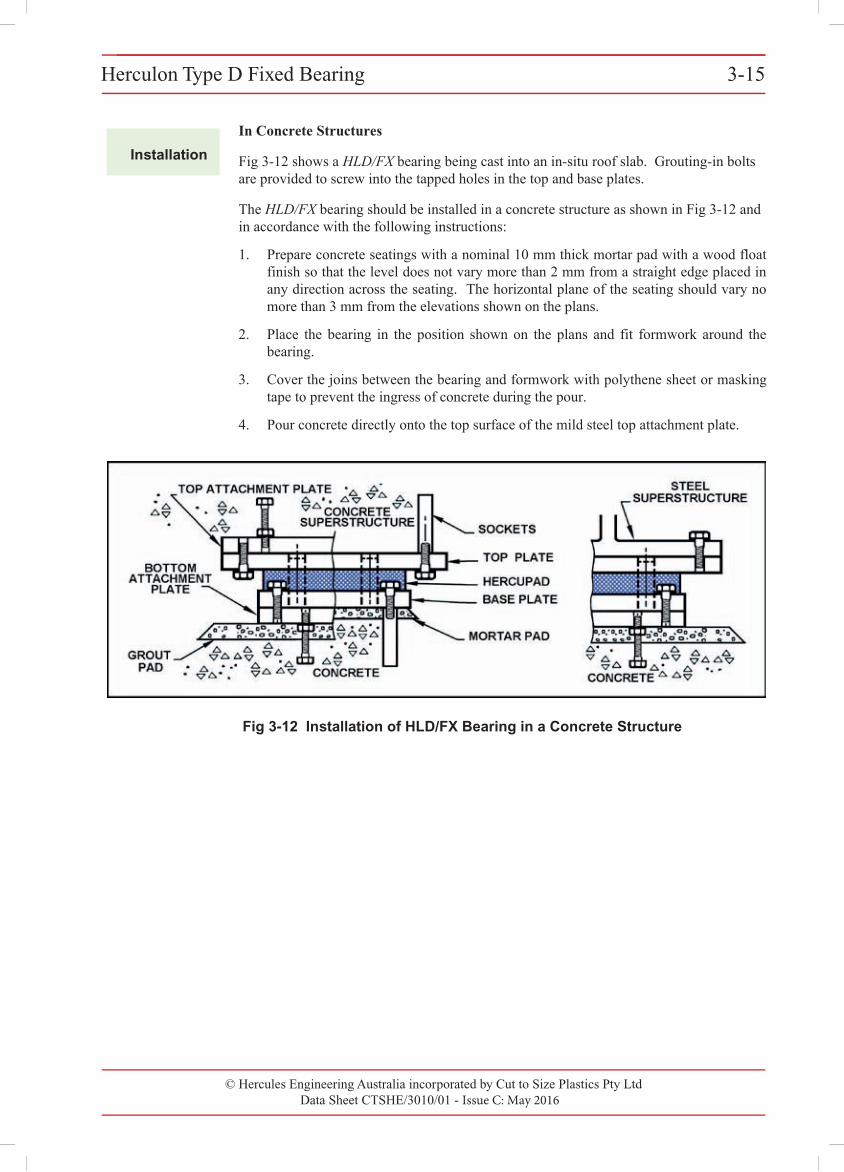
© Hercules Engineering Australia incorporated by Cut to Size Plastics Pty LtdData Sheet CTSHE/3010/01 - Issue C: May 2016
Herculon Type D Fixed Bearing 3-15Herculon Type D Fixed Bearing 3-15
© Cut to Size Plastics Pty Ltd incorporating Hercules Engineering AustraliaData Sheet CTSHE/3010/00 - Issue A: November 2000
Installation
In Concrete Structures
Fig 3-12 shows a HLD/FX bearing being cast into an in-situ roof slab. Grouting-in bolts are provided to screw into the tapped holes in the top and base plates.
The HLD/FX bearing should be installed in a concrete structure as shown in Fig 3-12 and in accordance with the following instructions:
1. Prepare concrete seatings with a nominal 10 mm thick mortar pad with a wood floatfinish so that the level does not vary more than 2 mm from a straight edge placed inany direction across the seating. The horizontal plane of the seating should vary nomore than 3 mm from the elevations shown on the plans.
2. Place the bearing in the position shown on the plans and fit formwork around thebearing.
3. Cover the joins between the bearing and formwork with polythene sheet or maskingtape to prevent the ingress of concrete during the pour.
4. Pour concrete directly onto the top surface of the mild steel top attachment plate.
Fig 3-12 Installation of HLD/FX Bearing in a Concrete Structure
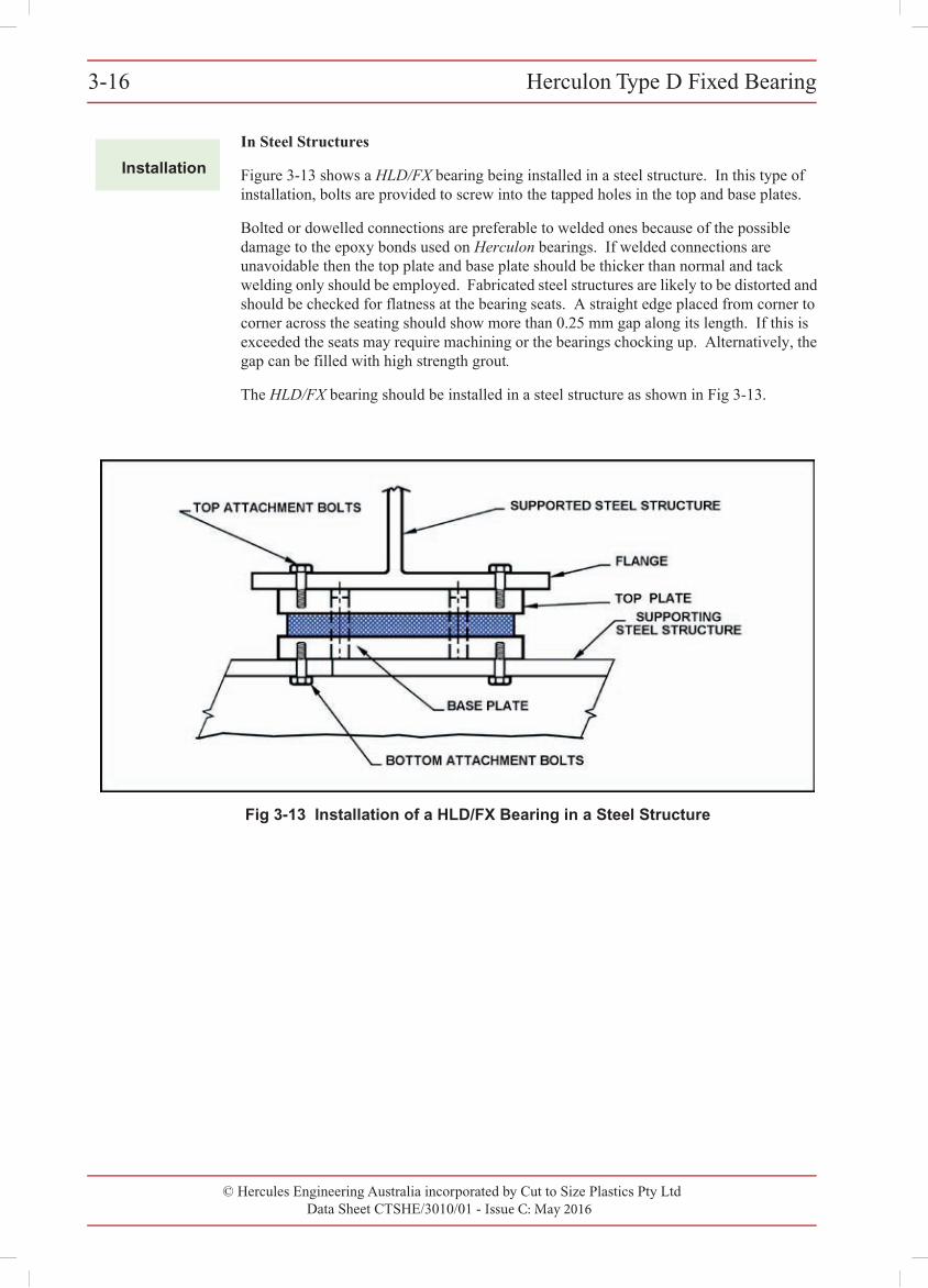
© Hercules Engineering Australia incorporated by Cut to Size Plastics Pty LtdData Sheet CTSHE/3010/01 - Issue C: May 2016
Herculon Type D Fixed Bearing3-163-16 Herculon Type D Fixed Bearing
© Cut to Size Plastics Pty Ltd incorporating Hercules Engineering AustraliaData Sheet CTSHE/3010/00 - Issue A: November 2000
Installation
In Steel Structures
Figure 3-13 shows a HLD/FX bearing being installed in a steel structure. In this type of installation, bolts are provided to screw into the tapped holes in the top and base plates.
Bolted or dowelled connections are preferable to welded ones because of the possible damage to the epoxy bonds used on Herculon bearings. If welded connections are unavoidable then the top plate and base plate should be thicker than normal and tack welding only should be employed. Fabricated steel structures are likely to be distorted and should be checked for flatness at the bearing seats. A straight edge placed from corner to corner across the seating should show more than 0.25 mm gap along its length. If this is exceeded the seats may require machining or the bearings chocking up. Alternatively, the gap can be filled with high strength grout.
The HLD/FX bearing should be installed in a steel structure as shown in Fig 3-13.
Fig 3-13 Installation of a HLD/FX Bearing in a Steel Structure
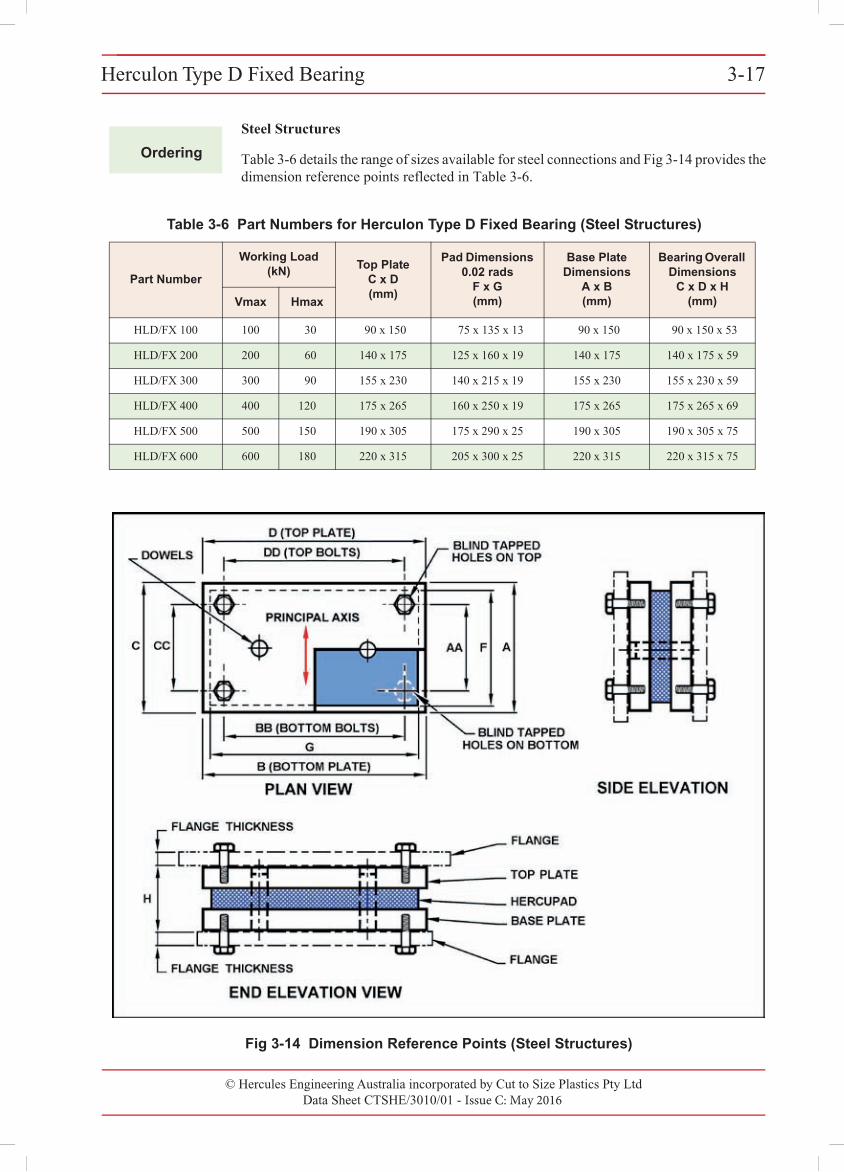
© Hercules Engineering Australia incorporated by Cut to Size Plastics Pty LtdData Sheet CTSHE/3010/01 - Issue C: May 2016
Herculon Type D Fixed Bearing 3-17Herculon Type D Fixed Bearing 3-17
© Cut to Size Plastics Pty Ltd incorporating Hercules Engineering AustraliaData Sheet CTSHE/3010/00 - Issue A: November 2000
Ordering
Steel Structures
Table 3-6 details the range of sizes available for steel connections and Fig 3-14 provides the dimension reference points reflected in Table 3-6.
Fig 3-14 Dimension Reference Points (Steel Structures)
Table 3-6 Part Numbers for Herculon Type D Fixed Bearing (Steel Structures)
Part Number
Working Load (kN) Top Plate
C x D(mm)
Pad Dimensions 0.02 rads
F x G(mm)
Base Plate Dimensions
A x B (mm)
Bearing Overall Dimensions
C x D x H(mm)Vmax Hmax
HLD/FX 100 100 30 90 x 150 75 x 135 x 13 90 x 150 90 x 150 x 53
HLD/FX 200 200 60 140 x 175 125 x 160 x 19 140 x 175 140 x 175 x 59
HLD/FX 300 300 90 155 x 230 140 x 215 x 19 155 x 230 155 x 230 x 59
HLD/FX 400 400 120 175 x 265 160 x 250 x 19 175 x 265 175 x 265 x 69
HLD/FX 500 500 150 190 x 305 175 x 290 x 25 190 x 305 190 x 305 x 75
HLD/FX 600 600 180 220 x 315 205 x 300 x 25 220 x 315 220 x 315 x 75
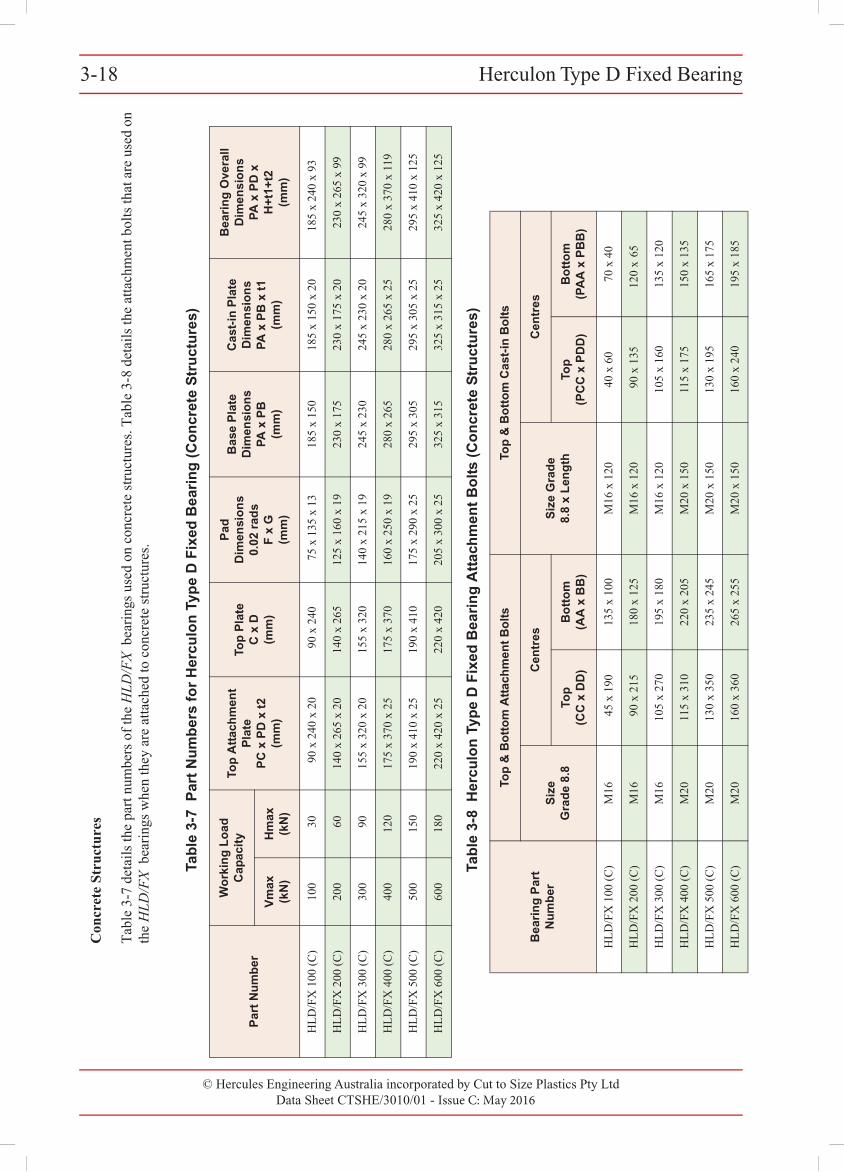
3-18 Herculon Type D Fixed Bearing
© Cut to Size Plastics Pty Ltd incorporating Hercules Engineering AustraliaData Sheet CTSHE/3010/00 - Issue A: November 2000
Con
cret
e St
ruct
ures
Tabl
e 3-
7 de
tails
the
part
num
bers
of t
he H
LD
/FX
bea
rings
use
d on
con
cret
e st
ruct
ures
. Tab
le 3
-8 d
etai
ls th
e at
tach
men
t bol
ts th
at a
re u
sed
on
the
HL
D/F
X b
earin
gs w
hen
they
are
atta
ched
to c
oncr
ete
stru
ctur
es.
Tab
le 3
-7 P
art
Nu
mb
ers
for
Her
culo
n T
ype
D F
ixed
Bea
rin
g (
Co
ncr
ete
Str
uct
ure
s)
Par
t N
um
ber
Wo
rkin
g L
oad
C
apac
ity
Top
Att
ach
men
t P
late
PC
x P
D x
t2
(mm
)
Top
Pla
te
C x
D
(mm
)
Pad
D
imen
sio
ns
0.02
rad
sF
x G
(mm
)
Bas
e P
late
D
imen
sio
ns
PA
x P
B(m
m)
Cas
t-in
Pla
te
Dim
ensi
on
sP
A x
PB
x t
1(m
m)
Bea
rin
g O
vera
ll D
imen
sio
ns
PA
x P
D x
H
+t1
+t2
(mm
)V
max
(k
N)
Hm
ax
(kN
)
HLD
/FX
100
(C)
100
3090
x 2
40 x
20
90 x
240
75 x
135
x 1
318
5 x
150
185
x 15
0 x
2018
5 x
240
x 93
HLD
/FX
200
(C)
200
6014
0 x
265
x 20
140
x 26
512
5 x
160
x 19
230
x 17
523
0 x
175
x 20
230
x 26
5 x
99
HLD
/FX
300
(C)
300
9015
5 x
320
x 20
155
x 32
014
0 x
215
x 19
245
x 23
024
5 x
230
x 20
245
x 32
0 x
99
HLD
/FX
400
(C)
400
120
175
x 37
0 x
2517
5 x
370
160
x 25
0 x
1928
0 x
265
280
x 26
5 x
2528
0 x
370
x 11
9
HLD
/FX
500
(C)
500
150
190
x 41
0 x
2519
0 x
410
175
x 29
0 x
2529
5 x
305
295
x 30
5 x
2529
5 x
410
x 12
5
HLD
/FX
600
(C)
600
180
220
x 42
0 x
2522
0 x
420
205
x 30
0 x
2532
5 x
315
325
x 31
5 x
2532
5 x
420
x 12
5
Tab
le 3
-8 H
ercu
lon
Typ
e D
Fix
ed B
eari
ng
Att
ach
men
t B
olt
s (C
on
cret
e S
tru
ctu
res)
Bea
rin
g P
art
Nu
mb
er
Top
& B
ott
om
Att
ach
men
t B
olt
sTo
p &
Bo
tto
m C
ast-
in B
olt
s
Siz
e G
rad
e 8.
8
Cen
tres
Siz
e G
rad
e 8.
8 x
Len
gth
Cen
tres
Top
(C
C x
DD
)B
ott
om
(AA
x B
B)
Top
(PC
C x
PD
D)
Bo
tto
m
(PA
A x
PB
B)
HLD
/FX
100
(C)
M16
45 x
190
135
x 10
0M
16 x
120
40 x
60
70 x
40
HLD
/FX
200
(C)
M16
90 x
215
180
x 12
5M
16 x
120
90 x
135
120
x 65
HLD
/FX
300
(C)
M16
105
x 27
019
5 x
180
M16
x 1
2010
5 x
160
135
x 12
0
HLD
/FX
400
(C)
M20
115
x 31
022
0 x
205
M20
x 1
5011
5 x
175
150
x 13
5
HLD
/FX
500
(C)
M20
130
x 35
023
5 x
245
M20
x 1
5013
0 x
195
165
x 17
5
HLD
/FX
600
(C)
M20
160
x 36
026
5 x
255
M20
x 1
5016
0 x
240
195
x 18
5
© Hercules Engineering Australia incorporated by Cut to Size Plastics Pty LtdData Sheet CTSHE/3010/01 - Issue C: May 2016
Herculon Type D Fixed Bearing3-18
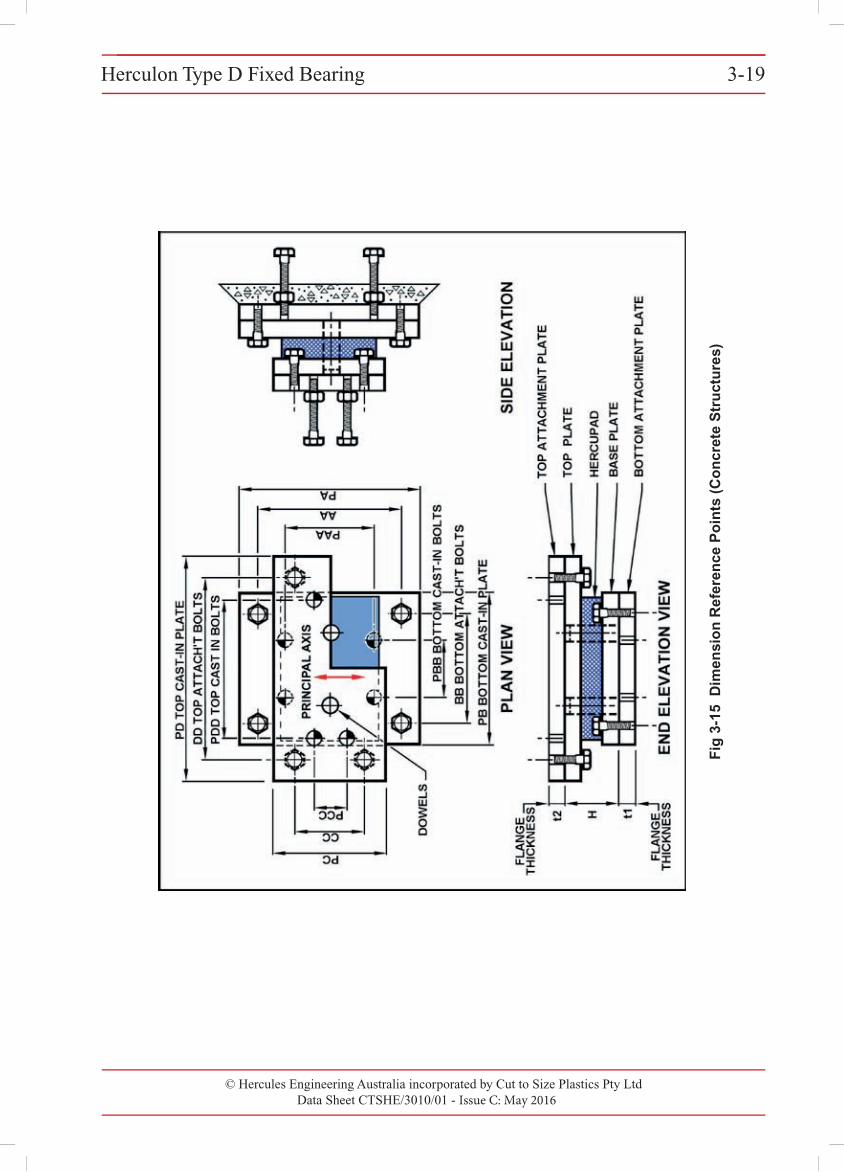
Herculon Type D Fixed Bearing 3-19
© Cut to Size Plastics Pty Ltd incorporating Hercules Engineering AustraliaData Sheet CTSHE/3010/00 - Issue A: November 2000
Fig
3-1
5 D
imen
sio
n R
efer
ence
Po
ints
(C
on
cret
e S
tru
ctu
res)
© Hercules Engineering Australia incorporated by Cut to Size Plastics Pty LtdData Sheet CTSHE/3010/01 - Issue C: May 2016
Herculon Type D Fixed Bearing 3-19
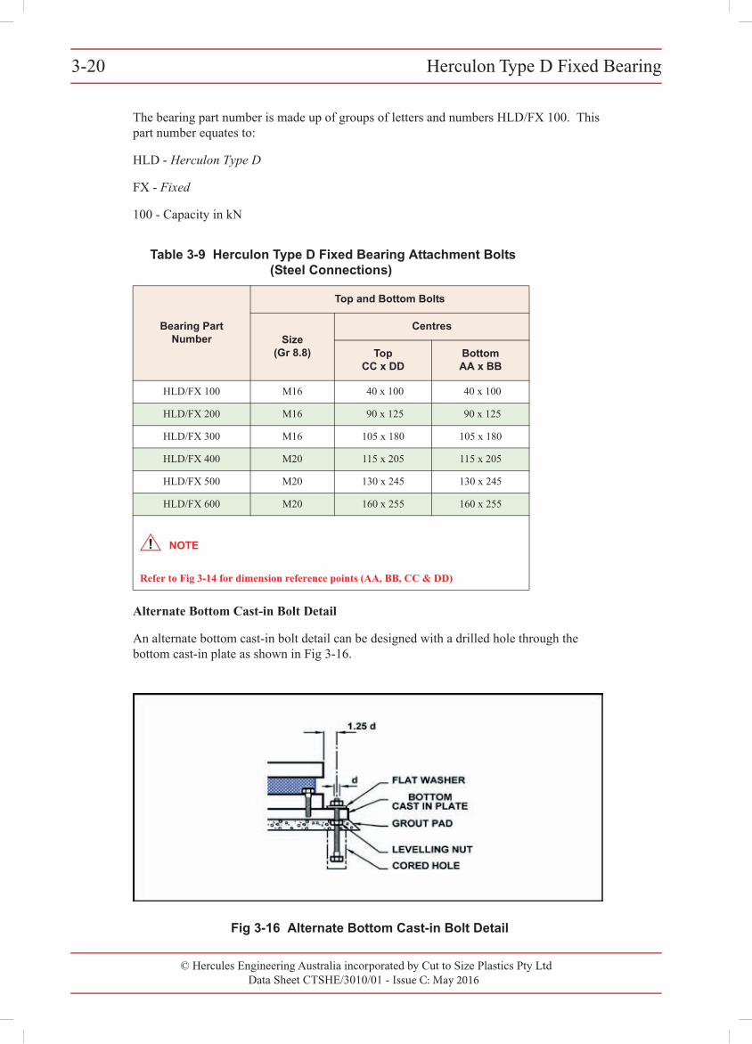
© Hercules Engineering Australia incorporated by Cut to Size Plastics Pty LtdData Sheet CTSHE/3010/01 - Issue C: May 2016
Herculon Type D Fixed Bearing3-203-20 Herculon Type D Fixed Bearing
© Cut to Size Plastics Pty Ltd incorporating Hercules Engineering AustraliaData Sheet CTSHE/3010/00 - Issue A: November 2000
The bearing part number is made up of groups of letters and numbers HLD/FX 100. This part number equates to:
HLD - Herculon Type D
FX - Fixed
100 - Capacity in kN
Alternate Bottom Cast-in Bolt Detail
An alternate bottom cast-in bolt detail can be designed with a drilled hole through the bottom cast-in plate as shown in Fig 3-16.
Fig 3-16 Alternate Bottom Cast-in Bolt Detail
Table 3-9 Herculon Type D Fixed Bearing Attachment Bolts (Steel Connections)
Bearing Part Number
Top and Bottom Bolts
Size (Gr 8.8)
Centres
TopCC x DD
BottomAA x BB
HLD/FX 100 M16 40 x 100 40 x 100
HLD/FX 200 M16 90 x 125 90 x 125
HLD/FX 300 M16 105 x 180 105 x 180
HLD/FX 400 M20 115 x 205 115 x 205
HLD/FX 500 M20 130 x 245 130 x 245
HLD/FX 600 M20 160 x 255 160 x 255
NOTE
Refer to Fig 3-14 for dimension reference points (AA, BB, CC & DD)
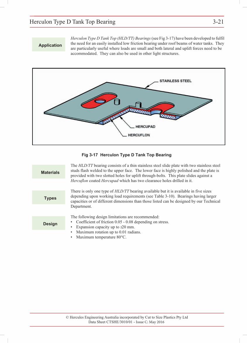
© Hercules Engineering Australia incorporated by Cut to Size Plastics Pty LtdData Sheet CTSHE/3010/01 - Issue C: May 2016
Herculon Type D Tank Top Bearing 3-21Herculon Type D Tank Top Bearing 3-21
© Cut to Size Plastics Pty Ltd incorporating Hercules Engineering AustraliaData Sheet CTSHE/3010/00 - Issue A: November 2000
3
Application
Herculon Type D Tank Top (HLD/TT) Bearings (see Fig 3-17) have been developed to fulfil the need for an easily installed low friction bearing under roof beams of water tanks. They are particularly useful where loads are small and both lateral and uplift forces need to be accommodated. They can also be used in other light structures.
Fig 3-17 Herculon Type D Tank Top Bearing
Materials
The HLD/TT bearing consists of a thin stainless steel slide plate with two stainless steel studs flash welded to the upper face. The lower face is highly polished and the plate is provided with two slotted holes for uplift through-bolts. This plate slides against a Hercuflon coated Hercupad which has two clearance holes drilled in it.
Types
There is only one type of HLD/TT bearing available but it is available in five sizes depending upon working load requirements (see Table 3-10). Bearings having larger capacities or of different dimensions than those listed can be designed by our Technical Department.
Design
The following design limitations are recommended:• Coefficient of friction 0.05 - 0.08 depending on stress.• Expansion capacity up to ±20 mm.• Maximum rotation up to 0.01 radians.• Maximum temperature 80°C.
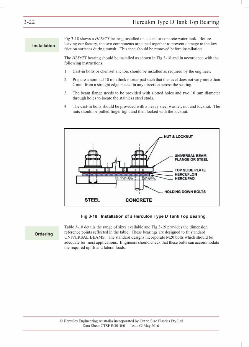
© Hercules Engineering Australia incorporated by Cut to Size Plastics Pty LtdData Sheet CTSHE/3010/01 - Issue C: May 2016
Herculon Type D Tank Top Bearing3-223-22 Herculon Type D Tank Top Bearing
© Cut to Size Plastics Pty Ltd incorporating Hercules Engineering AustraliaData Sheet CTSHE/3010/00 - Issue A: November 2000
Installation
Fig 3-18 shows a HLD/TT bearing installed on a steel or concrete water tank. Before leaving our factory, the two components are taped together to prevent damage to the low friction surfaces during transit. This tape should be removed before installation.
The HLD/TT bearing should be installed as shown in Fig 3-18 and in accordance with the following instructions:
1. Cast-in bolts or chemset anchors should be installed as required by the engineer.
2. Prepare a nominal 10 mm thick mortar pad such that the level does not vary more than2 mm from a straight edge placed in any direction across the seating.
3. The beam flange needs to be provided with slotted holes and two 10 mm diameterthrough holes to locate the stainless steel studs.
4. The cast-in bolts should be provided with a heavy steel washer, nut and locknut. Thenuts should be pulled finger tight and then locked with the locknut.
Fig 3-18 Installation of a Herculon Type D Tank Top Bearing
Ordering
Table 3-10 details the range of sizes available and Fig 3-19 provides the dimension reference points reflected in the table. These bearings are designed to fit standard UNIVERSAL BEAMS. The standard designs incorporate M20 bolts which should be adequate for most applications. Engineers should check that these bolts can accommodate the required uplift and lateral loads.
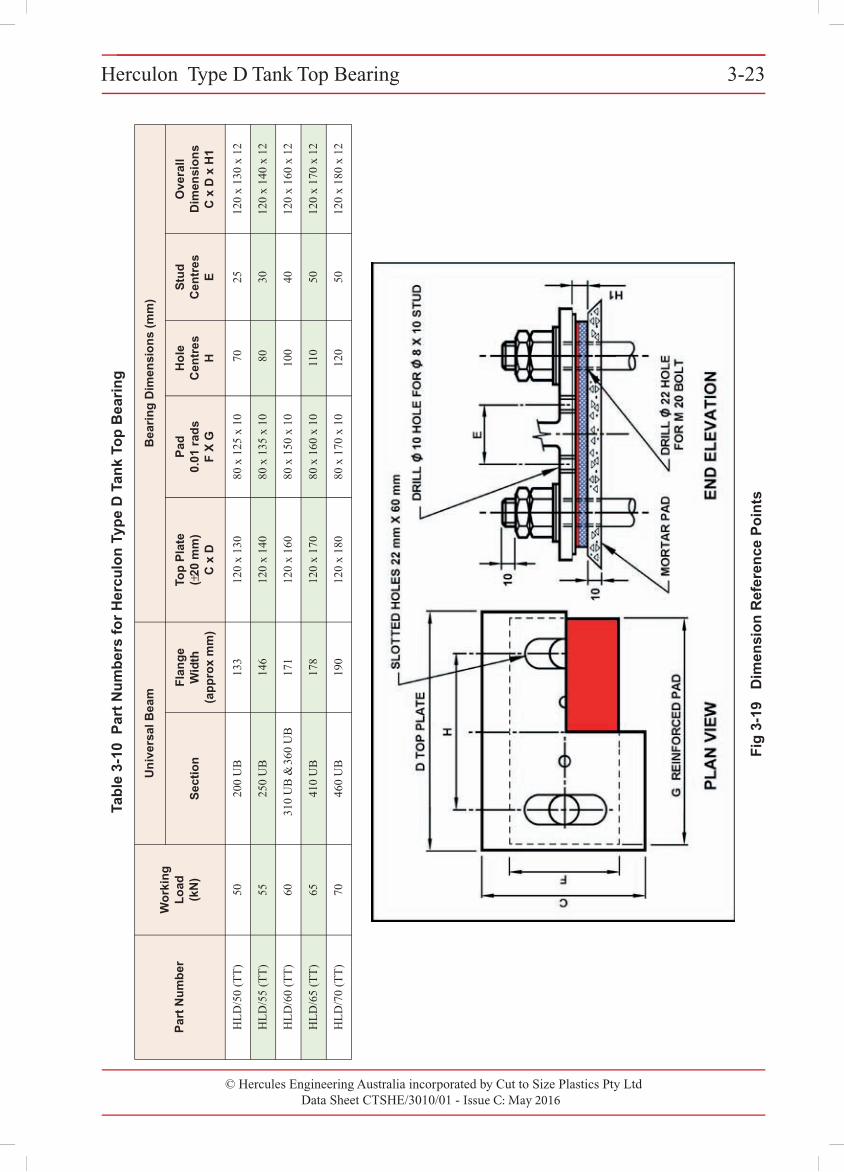
© Hercules Engineering Australia incorporated by Cut to Size Plastics Pty LtdData Sheet CTSHE/3010/01 - Issue C: May 2016
Herculon Type D Tank Top Bearing 3-23
Tab
le 3
-10
Par
t N
um
ber
s fo
r H
ercu
lon
Typ
e D
Tan
k To
p B
eari
ng
Par
t N
um
ber
Wo
rkin
g
Lo
ad(k
N)
Un
iver
sal B
eam
Bea
rin
g D
imen
sio
ns
(mm
)
Sec
tio
nF
lan
ge
Wid
th(a
pp
rox
mm
)
Top
Pla
te(±
20 m
m)
C x
D
Pad
0.01
rad
sF
X G
Ho
le
Cen
tres
H
Stu
d
Cen
tres
E
Ove
rall
Dim
ensi
on
sC
x D
x H
1
HLD
/50
(TT)
5020
0 U
B13
312
0 x
130
80 x
125
x 1
070
2512
0 x
130
x 12
HLD
/55
(TT)
5525
0 U
B14
612
0 x
140
80 x
135
x 1
080
3012
0 x
140
x 12
HLD
/60
(TT)
60 3
10 U
B &
360
UB
171
120
x 16
080
x 1
50 x
10
100
4012
0 x
160
x 12
HLD
/65
(TT)
6541
0 U
B17
812
0 x
170
80 x
160
x 1
011
050
120
x 17
0 x
12
HLD
/70
(TT)
7046
0 U
B19
012
0 x
180
80 x
170
x 1
012
050
120
x 18
0 x
12
Herculon Type D Tank Top Bearing 3-23
© Cut to Size Plastics Pty Ltd incorporating Hercules Engineering AustraliaData Sheet CTSHE/3010/00 - Issue A: November 2000
Fig
3-1
9 D
imen
sio
n R
efer
ence
Po
ints
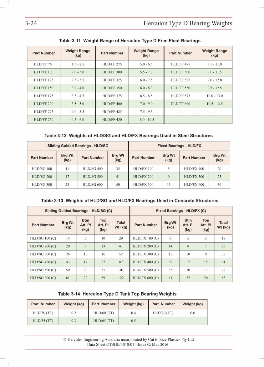
3-24 Herculon Type D Bearing Weights
© Cut to Size Plastics Pty Ltd incorporating Hercules Engineering AustraliaData Sheet CTSHE/3010/00 - Issue A: November 2000
3
Table 3-11 Weight Range of Herculon Type D Free Float Bearings
Part NumberWeight Range
(kg)Part Number
Weight Range (kg)
Part NumberWeight Range
(kg)
HLD/FF 75 1.5 - 2.5 HLD/FF 275 5.0 - 6.5 HLD/FF 475 8.5 - 11.0
HLD/FF 100 2.0 - 3.0 HLD/FF 300 5.5 - 7.0 HLD/FF 500 9.0 - 11.5
HLD/FF 125 2.5 - 3.5 HLD/FF 325 6.0 - 7.5 HLD/FF 525 9.0 - 12.0
HLD/FF 150 3.0 - 4.0 HLD/FF 350 6.0 - 8.0 HLD/FF 550 9.5 - 12.5
HLD/FF 175 3.5 - 4.5 HLD/FF 375 6.5 - 8.5 HLD/FF 575 10.0 - 13.0
HLD/FF 200 3.5 - 5.0 HLD/FF 400 7.0 - 9.0 HLD/FF 600 10.5 - 13.5
HLD/FF 225 4.0 - 5.5 HLD/FF 425 7.5 - 9.5 - -
HLD/FF 250 4.5 - 6.0 HLD/FF 450 8.0 - 10.5 - -
Table 3-12 Weights of HLD/SG and HLD/FX Bearings Used in Steel Structures
Sliding Guided Bearings - HLD/SG Fixed Bearings - HLD/FX
Part NumberBrg Wt
(kg)Part Number
Brg Wt (kg)
Part NumberBrg Wt
(kg)Part Number
Brg Wt (kg)
HLD/SG 100 11 HLD/SG 400 35 HLD/FX 100 5 HLD/FX 400 20
HLD/SG 200 17 HLD/SG 500 41 HLD/FX 200 9 HLD/FX 500 25
HLD/SG 300 23 HLD/SG 600 50 HLD/FX 300 13 HLD/FX 600 30
Table 3-13 Weights of HLD/SG and HLD/FX Bearings Used in Concrete Structures
Sliding Guided Bearings - HLD/SG (C) Fixed Bearings - HLD/FX (C)
Part NumberBrg Wt
(kg)
Btm Att. Pl (kg)
Top Att. Pl (kg)
Total Wt (kg)
Part NumberBrg Wt
(kg)
Btm Att. Pl (kg)
Top Att. Pl (kg)
Total Wt (kg)
HLD/SG 100 (C) 14 5 10 29 HLD/FX 100 (C) 9 5 5 19
HLD/SG 200 (C) 20 8 13 41 HLD/FX 200 (C) 14 8 7 29
HLD/SG 300 (C) 26 10 16 52 HLD/FX 300 (C) 18 10 9 37
HLD/SG 400 (C) 43 17 27 87 HLD/FX 400 (C) 29 17 15 61
HLD/SG 500 (C) 50 20 31 101 HLD/FX 500 (C) 35 20 17 72
HLD/SG 600 (C) 61 22 39 122 HLD/FX 600 (C) 41 22 20 83
Table 3-14 Herculon Type D Tank Top Bearing Weights
Part Number Weight (kg) Part Number Weight (kg) Part Number Weight (kg)
HLD/50 (TT) 0.2 HLD/60 (TT) 0.4 HLD/70 (TT) 0.6
HLD/55 (TT) 0.3 HLD/65 (TT) 0.5 -
© Hercules Engineering Australia incorporated by Cut to Size Plastics Pty LtdData Sheet CTSHE/3010/01 - Issue C: May 2016
Herculon Type D Bearing Weights3-24