Embed Size (px)
Citation preview
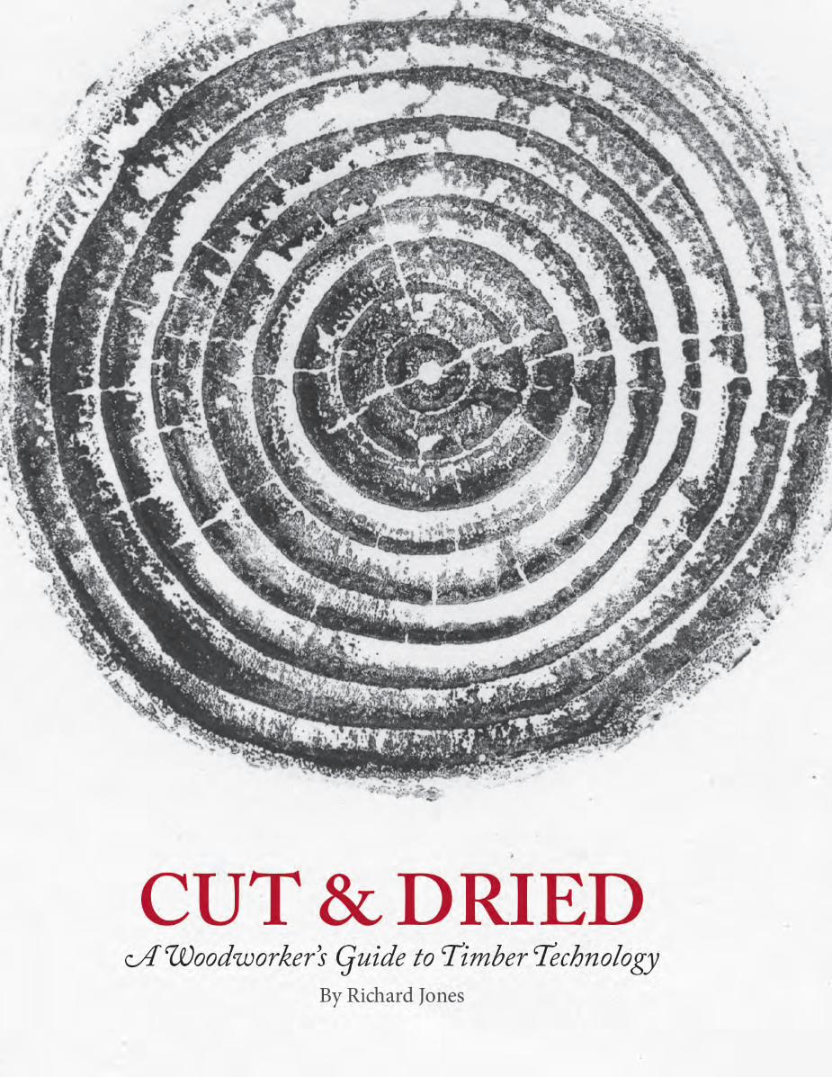

Cut & Dried

CUT & DRIEDA Woodworker’s Guide to Timber Technology
Richard Jones
LOST ART PRESS : FORT MITCHELL
First published by Lost Art Press LLC in 201826 Greenbriar Ave., Fort Mitchell, KY, 41017, USAWeb: http://lostartpress.com
Title: Cut & Dried: A Woodworker’s Guide to Timber TechnologyAuthor: Richard JonesPublisher: Christopher Schwarz Editor: Kara Gebhart UhlBook design and layout: Meghan BatesIllustrator: Richard Jones Copy editor: Megan FitzpatrickIndex: Rachel Nishan from Twin Oaks Indexing (www.twinoaks.org)Distribution: John Hoffman
Copyright © 2018 by Richard Jones. All rights reserved
ISBN: 978-0-9978702-9-9
First printing.
ALL RIGHTS RESERVEDNo part of this book may be reproduced in any form or by any electronic or mechanical means including information storage and retrieval systems without permission in writing from the publisher; except by a reviewer, who may quote brief passages in a review.
This book was printed and bound in the United States.
Foreword ix Acknowledgements xi1. Introduction 3 1.1 The Ubiquitous Oak 5 1.2 Balanoculture 8 1.3 Oak: Partner of Mankind 8 1.4 United Kingdom of Great Britain Tree Cover 10 1.5 The Romans & Later Centuries 11 1.6 The ‘Baltic Problem’ 12 1.7 Tree History, Oddities, & Tree Migrations 14 1.8 The Latin Binomial System 152. Tree Distribution 19 2.1 Equatorial Rainforest 19 2.2 Montane Tropics 19 2.3 Monsoon Forest 20 2.4 Savannah & Desert 20 2.5 Mediterranean Forest 20 2.6 Temperate Forest 20 2.7 Boreal Forest & the Taiga 20 2.8 Tundra 213. Tree Classification, Growth & Structure 23 3.1 Log Cross Section 25 3.2 Gymnosperms & Angiosperms – Differences 274. Roots, Leaves, Seeds, Flowers, Germination, Transpiration, Woodland Regeneration 29 4.1 Roots 29 4.2 Buds 32 4.3 Leaves 35 4.4 Flowers 37 4.5 Seeds & Germination 38 4.6 Transpirational Pull & Root Pressure 40 4.7 Woodland Regeneration 42 4.8 Characteristics Found in Deciduous Trees 425. Felling, Conversion & Yield 47 5.1 Viable Wood for Conversion 48 5.2 Felling, Logging, Harvesting 49 5.3 Conversion of Wood 51 5.4 Measuring Log Yield 64 5.5 Hoppus Feet 64 5.6 Doyle Scale 65
Contents
6. Water, Water Vapour & Wood 69 6.1 Atmospheric Humidity 69 6.2 Water in Wood 72 6.3 Hysteresis 75 6.4 Moisture Gain & Loss in Wood – An Analogy 75 6.5 Fibre Saturation Point 75 6.6 Measuring Wood Moisture Content 76 6.7 Microwave Oven Drying 77 6.8 Moisture Meters 78 6.9 Green Wood Use & Chair Bodging 79 6.10 Wood Moisture Content Percentages & Appropriate Timber Use 80 6.11 Atmospheric RH – Its Effect on Wood MC 81 6.12 Allowing for Changes in Wood Moisture Content 85 6.13 Moisture Content & Dimensional Change in Wood 86 6.14 Tangential, Radial, Longitudinal Shrinkage 88 6.15 Sapwood Movement & its Use in Projects 897. Coping with Wood Movement 93 7.1 Dimensional Change & Stability 94 7.2 Calculating Wood Movement 95 7.3 Sample Wood Expansion & Contraction Calculations 97 7.4 Distortion – Warping, Cupping, Bowing etc. 98 7.5 Wood Movement & Joinery 104 7.6 Built-up Laminations 105 7.7 End Grain Orientation & Panel Glue-ups 107 7.8 Wide Boards 109 7.9 Chatoyance Considerations 109 7.10 Edge Joinery 110 7.11 Storing a Panel Between Glue-up & Use 112 7.12 Mitres & Movement 113 7.13 Moisture Cycling 114 7.14 Moisture Cycling in Table & Cabinet Tops 115 7.15 Water Damage: Surface Checking & Cupping 115 7.16 Stress Release in Wood During Ripping: Kickback 1158. Seasoning or Drying of Wood 119 8.1 Drying Wood Using Air 120 8.2. Wood Moisture Content in Response to Temperature & Relative Humidity 122 8.3 Stickers & Stickering 123 8.4 Air Drying 125 8.5 Advanced Air-drying Methods 129 8.6 Wood-drying Kilns 130 8.7 Circulating Air, Monitors & Kiln Controls 134 8.8 Kiln Drying Schedules 138 8.9 Special Kiln Treatments 139 8.10 Kiln Drying Standards 1439. Drying Faults 147 9.1 Case-hardening & Reverse Case-hardening 149 9.2. Seasoning-induced Wood Discolouration 150
10. From the Kiln to the User 155 10.1 Green or Dry Tally? 157 10.2 Visual Grading of Timber (Lumber in North America) 157 10.3 American Appearance Grading 157 10.4 U.K. Appearance Grading 161 10.5 Measuring Planks or Boards in the U.K. 162 10.6 Appearance Grading of Oak Grown in Mainland Europe 163 10.7 General Wood Buying Tips 16511. Fungi & Wood 169 11.1 Physiology & Structure 169 11.2 Beneficial Fungi 171 11.3 Unwelcome Fungi 173 11.4 ‘Beautifying’ Fungi 180 11.5 Health Risks of Fungi 18312. Insect Pests 187 12.1 Termites 187 12.2 Common Furniture Beetle – Anobium punctatum 190 12.3 Death-watch Beetle – Xestobium rufovillosum 192 12.4 Powder Post Beetle – Lyctus Beetle 192 12.5 Pinhole Borers – Ambrosia Beetles 193 12.6 House Longhorn Beetle – Hylotrupes 194 12.7 Leaf-miner Flies – Pith Fleck 195 12.8 Carpenter Ants (Camponotus species) 195 12.9 Bees and Wasps 196 12.10 Insect Pest Control, Eradication & Deterrents 197 13. Characteristics of Timber 203 13.1 Grain 203 13.2 Knots – Knot Formation & Structure 210 13.3 Shakes 21414. Wood Strength & Structures 219 14.1 Frequently-tested Strength Properties 220 14.2 Rarer Strength Properties 222 14.3 Wood Strength Testing 224 14.4 Stress, Strain & Strength 228 14.5 Additional Factors Affecting Strength 232 14.6 Deformation in Pure Bending 235 14.7 Strength Grading of Structural Timber 240 14.8 Structures 24415. Ecological & Environmental Issues 253 15.1 Worldwide Forest Coverage & Wood Extraction 254 15.2 Non-Wood Forest Products (NWFPs) 256 15.3 Wood Consumption 257 15.4 Tree Planting, Ownership & Management Responsibility 260 15.5 Growth of Forest Protection Efforts 261 15.6 Considerate Usage of Forest Products 265 About the Author 271 Glossary 273 Bibliography 287 Websites 306 Appendix 309

ix
When I began working as a furniture maker I knew little of trees, their
varieties, their adaptability to a wide range of climates, their life cycle or their history. My interest really focused only on the wood in front of me and what my em-ployer expected me to do with it. At that early stage in my career I quickly learnt to recognise a board of English oak, but I found it harder to recognise a live oak tree in a hedgerow.
As my skills in the trade improved I re-alised living trees, their felling, conversion and other factors affect how wood behaves as we work it and how it performs in ser-vice. I set about increasing my knowledge. I quickly discovered many facts such as the range of influences affecting the char-acter and form of the living tree: its spe-cies, the climate it experiences, the nature of the soil, its elevation above sea level, the competition it faces for space etc. I became hooked, and as the years passed
Foreword
I found the study of trees and wood more engrossing. They are for me fascinating life forms, and I have come to regard them as things of wonder and great beauty. My approach to the subject is widely focused, a different point of view perhaps to one conceivably employed by a specialist wood scientist or a timber technologist investi-gating specific characteristics or fields of study.
My interests were piqued by an eclectic mix, including trees and history, trees and social affairs, environmental issues and political issues related to trees and forests; all of these topics, and more, are supple-mental to the essential knowledge wood-workers need to understand and work the material successfully. I have always felt, as a furniture designer, and not a wood scien-tist, I had the luxury to explore the subject of trees and wood quite widely. It’s true, as woodworkers, we need to know how wood expands and contracts across the
grain when it takes on or loses moisture, and it’s helpful to know how to calculate the likely range of movement; but know-ing only the dry technical elements of the subject divorces us from the essential role trees and forests, and the wood and other products we got from them play. Trees and wood have all played a role in man-kind’s ability to survive and develop, our religions, our economies, the rise and fall of empires and city states, our medicine, our diet and so on. I have found my ex-ploration into the wide range of subjects associated with trees and wood gives me a rounded knowledge affecting my ability to work wood with confidence, and helps me discuss related matters such as politics, envrionmental issues and human history affected by trees and wood both with cus-tomers, and new and experienced wood-workers. I believe others will find similar benefits through reading this book.
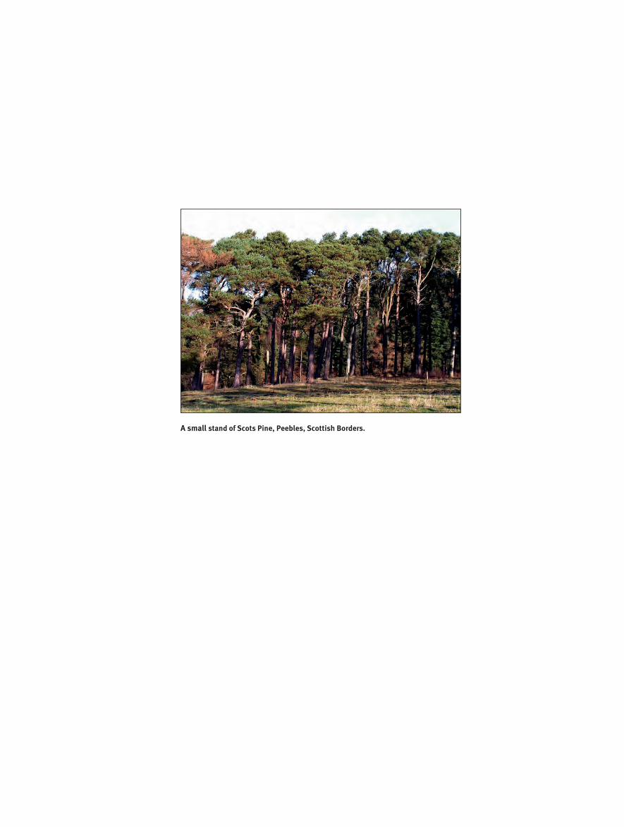
A small stand of Scots Pine, Peebles, Scottish Borders.
The writing of this manuscript owes much to the following peo-ple, each of who provided assis-
tance in a variety of ways. Without their help this text would have been so much the poorer. I thank each of them for their support, kindness, patience and generosity of spirit.
Dr. Stephen Compton, Reader in Ento-mology, Institute of Integrative and Com-parative Biology, University of Leeds, who reviewed the section on insect pests and wood, and provided specialist knowledge and suggestions to improve the text and content. David Pinniger, BSc (Hons) in Zoology, MIBiol, FRES, MBE of DBP Entomology was also kind enough to review this section and provided photo-graphs of insects to illustrate the text.
Frank Hird, owner of Nidd Valley Saw-mills, Yorkshire, for generous access to his timber yard and its operations. Similar thanks go to Tino Rawnsley of Rawnsley Woodland Products, Cornwall, for allow-ing me to photograph his solar kiln.
Acknowledgements
Professor Eugene Wengert, Extension Specialist, University of Wisconsin-Mad-ison, for his review of the wood season-ing and drying faults text. He provided numerous suggestions for improvement. Similarly, Geoff Cooper, Senior Consul-tant, Building Research Establishment-Timber, Great Britain, provided valuable help with the same two sections.
Dr. Jeremy Knapp, Senior Lecturer, Institute of Integrative and Compara-tive Biology, University of Leeds, who reviewed the section on fungi and wood, and provided specialist knowledge and suggestions. Dr. Knapp also gave me per-mission to use some of his photographs to illustrate passages.
Mr. David Richardson, BEng, CEng, MIStructE, Senior Teaching Fellow, De-partment of Civil Engineering, Univer-sity of Leeds, for reviewing the section on Structures and Wood Strength for factual accuracy, assistance with formulae and calculations, and for making significant suggestions to improve the text.
Jack Metcalfe of Leeds Marquetry So-ciety provided veneer samples, which I prepared, polished and photographed.
John Robinson of Associated Timber Services (formerly Sewstern Timber), Lincolnshire, for talking to me about the kiln-drying operations he runs and gen-erously giving me permission to use the photographs I took of the kilns and yard.
James Hesketh, M(Eng) University of Leeds, who patiently helped me gain ad-ditional insight into the bending theory of beams.
Thorp Perrow Arboretum, Bedale, North Yorkshire, for granting me permis-sion to take and use photographs of vari-ous trees in their collection.
I am grateful to the following people for permitting me to use their photographs in the manuscript: Bill Tindall, Tennes-see; Spencer Hochstetler, Tennessee; Dr. Michael Kuo, Illinois; and Phil Lund of Timberwise (U.K.) Ltd., Cheshire, CW9 7XF.
xi

A Guide to Abbreviations Used in this Book
Acronym/Abbreviations MeaningAH: Absolute HumidityATFS: American Tree Farm SystemCites: Convention on the International Trade in Endangered SpeciesCoC: Chain of CustodyEMC: Equilibrium Moisture ContentEU: European UnionF1F: FAS One Face GradeFAS: First & Second Face GradeFSC: Forest Stewardship CouncilFSP: Fibre Saturation PointGlulam: Glued laminated timber (aka lumber in North America)ISO: International Organization for StandardizationISPM 15: International Standards For Phytosanitary Measures No. 15LVL: Laminated Veneered LumberM&T or M and T: mortice and tenonMC: Moisture ContentMDF: Medium Density FibreboardMOE: Modulus of ElasticityMOR: Modulus of RuptureMpa: MegapascalNo 1C: Number 1 Common Grade No 2AC: Number 2A Common Grade OSB: Orientated Strand BoardPa: PascalPEFC: Programme for the Endorsement of Forest CertificationPEG: Polyethylene glycolPSI: Pounds per square inchPSL: Parallel Strand LumberQ-F2X: Oak (Q) [Quercus] strip/square-edged timber (F), of second quality (2), with sapwood on one edge (X) [Example of European appearance grading of hardwoods]RH: Relative HumiditySFI: Sustainable Forest InitiativeSFM: Sustainable Forest ManagementSI: International System of Units: abbreviated from the French Système international d'unitésSM: Surface MeasureSZ: Shrinkage ZoneT/R: Tangential/Radial (tangential to radial shrinkage ratio)
93
7Coping with Wood Movement:Dimensional Change, Distortion, Moisture Cycling
& Stress Release (Kickback)
This is probably the topic most vexing for woodworkers. How often have you seen a door panel
shrunk so much there’s a gap between it and the frame mouldings, or it’s cracked from top to bottom? You are sure to have seen architraves (door facings) where once tightly mitred joints have developed gaps on the inside corners. Wood tabletops, flat when made, are sometimes hopelessly concave as seen from above and now are more akin to a skateboard park than an eating surface. Then there are solid-wood tabletops with two or three splits in them where at either end they are attached sol-idly to cross-grained clamps (aka bread-board ends).
All of these faults and failures can be at-tributed to the way wood reacts to mois-ture by expanding as it gets wetter and contracting as it dries. If the woodwork-er fails to work with the expanding and contracting hygroscopic nature of wood, failure is almost certain to follow. For in-stance, in the case of the cracked tabletop with the clamped ends described above, the woodworker may have mistakenly glued the clamp on solidly, or the maker could have made mortice and tenon joints where the mortices in the clamped end were too short in the length. This would prevent the tenons on the end of the planked top from moving side to side as the top expanded and contracted over the seasons.
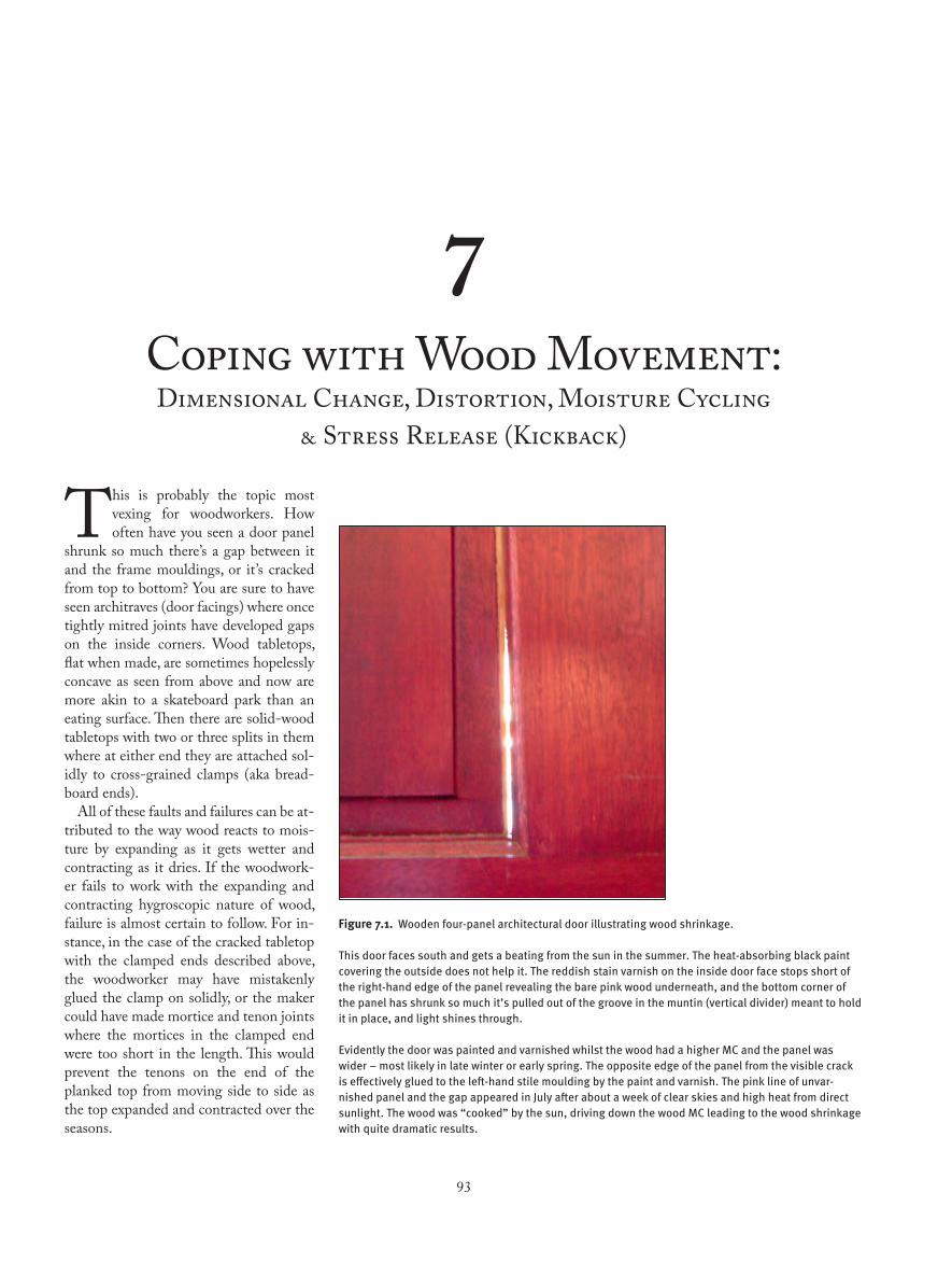
Figure 7.1. Wooden four-panel architectural door illustrating wood shrinkage. This door faces south and gets a beating from the sun in the summer. The heat-absorbing black paint covering the outside does not help it. The reddish stain varnish on the inside door face stops short of the right-hand edge of the panel revealing the bare pink wood underneath, and the bottom corner of the panel has shrunk so much it’s pulled out of the groove in the muntin (vertical divider) meant to hold it in place, and light shines through. Evidently the door was painted and varnished whilst the wood had a higher MC and the panel was wider – most likely in late winter or early spring. The opposite edge of the panel from the visible crack is effectively glued to the left-hand stile moulding by the paint and varnish. The pink line of unvar-nished panel and the gap appeared in July after about a week of clear skies and high heat from direct sunlight. The wood was “cooked” by the sun, driving down the wood MC leading to the wood shrinkage with quite dramatic results.
94 CHAPTER V11
The cause of the gaps described in the mitred corners of the door architrave is wood shrinkage. Typically in new house construction, the installation of doors, skirting (base) boards and other trim takes place before heating and cooling systems are installed and operational. The wood installed is often fairly wet at about 18 percent to 20 percent MC. Occupation of the house means the climate control system is switched on, which then dries the interior, including the wooden parts. The installed architrave loses moisture and shrink across the width. The outside corner of the mitre is fixed and, as the wood contracts, it shrinks from the inside edge toward the outside edge, causing the joint to open up.
The concave tabletop mentioned at the beginning may not be due to an error when it was made, but caused by moisture cycling, a subject discussed further in sec-tion 7.13.
Knowing approximately how much movement a particular species of timber exhibits during service is of great benefit to the woodworker. It means we are able to assess the allowance required to prevent drawers binding in humid periods of the year. Wide panels of solid wood expand and contract across the grain as the sea-sons change, and we can calculate how much tolerance is required for a tabletop to prevent it splitting.
Even quite narrow sections of wood move appreciably, and this is one con-tributing factor in joint failures that oc-cur over time due to moisture cycling. For example, most of us are familiar with door frame mortice and tenons with gaps at the shoulder line. Sometimes joint failure extends to the point where the door sags down from the hinged side. When this occurs, a common result is the leading edge at the bottom, opposite the hinged stile, drags on the floor in the case of ar-chitectural doors or, in cabinetry, across the inside upper face of the cabinet bot-tom.
Upon examination it’s often seen that pegged mortice and tenons show the peg or dowel sitting proud of the surrounding frame. Similarly, through-wedged mortice and tenons will show the end of the tenon and the wedges above the surface of the surrounding wood. At other times of the
year the end of the wedges and tenon sit below the outside surface of the morticed part.
7.1 Dimensional Change & StabilityThe difference between tangential move-ment and radial movement due to mois-ture gain or loss can be a source of trou-blesome wood. Certain woods are known to be stable and others are the opposite. Stable in this case refers to how much a piece of wood distorts as it shrink. Figure 7.5 provides a clue to working out which species fall into which category. The first piece of information to look for when as-sessing if a wood is likely to be unstable is large tangential and radial shrinkage factors. Secondly, the ratio of tangential-to-radial shrinkage also provides a clue. Radial shrinkage is always less than tan-gential shrinkage.
In the group of stable woods is Ameri-can mahogany with small tangential shrinkage of 5.1 percent and a similarly small radial shrinkage factor of 3.7 per-
Useful Rules of Thumb About Wood, Water & Movement Values
Two useful descriptions of the relationship between wood, its moisture con-tent, and the typical percentage change in its size in response to changes in
moisture content.Rule No. 1 (below) uses universally understood percentages factors.Rules 2 to 6 all state the same thing but use different systems of measure to say
it. Pick the statement that best suits you. For example, in the U.S. No. 4 will prob-ably be most apt. 1. Changing wood MC by between 3 percent and 4 percent causes it to shrink or grow approximately 1 percent across the grain. 2. 10 ft³ of wood gets wetter or drier by 1 percent MC when 3.2 Imperial pints of water are added or removed from it. 3. 10 ft³ of wood gets wetter or drier by 1 percent MC when 1.82 litres of water are added or removed from it. 4. 100 board feet of wood gets wetter or drier by 1 percent MC when 3.2 U.S. liquid pints of water are added or removed from it. 5. 100 board feet of wood gets wetter or drier by 1 percent MC when 1.51 litres of water are added or removed from it. 6. 1 cubic metre of wood gets wetter or drier by 1 percent MC when 6.36 litres of water are added or removed from it.
The above rules are not absolutely accurate in all circumstances, as is discussed in other parts of the text, but they are nevertheless useful.
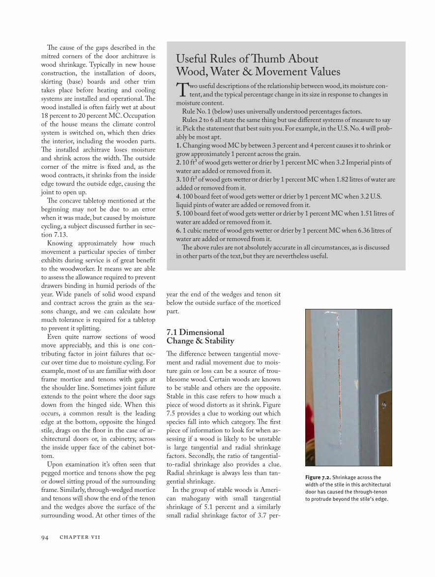
Figure 7.2. Shrinkage across the width of the stile in this architectural door has caused the through-tenon to protrude beyond the stile’s edge.
Coping with Wood Movement 95
cent as measured from 30 percent to 0 percent MC (green to oven dry). The tan-gential-to-radial (T/R) shrinkage ratio is also low at 1.4 found by the sum:
Tangential shrinkage factor / radial shrinkage factor = tangential to radial ra-tio. The sum therefore is, 5.1 / 3.7 = 1.4 (Hoadley1, 2000, p 116).
In the second table of unstable timbers, beech exhibits high-shrinkage percent-ages for both tangential and radial move-ment, along with a high T/R ratio.
Generally speaking, timbers with a T/R ratio close to 1:1 tend to be more stable. The tangential and radial shrinkage fac-tors might both be large or both be small, but it’s the ratio between the shrinkage factors that gives the best clue to stabil-ity. In other words, if shrinkage is large in one direction (tangentially) but small in the other (radially) there is a large differ-ential shrinkage pattern, meaning uneven transverse sectional shrinkage as viewed from the end of a board, and this leads to greater distortion, i.e., instability. If the amount of transverse shrinkage is very similar in both directions the shrinkage is more even and much-less prone to distor-tion and is therefore likely to be stable.
Although tangential and radial shrink-age factors vary significantly from species to species, and T/R ratios are also simi-larly varied, there are some useful aver-age applicable numbers. Taking all spe-cies into account, the average shrinkage of wood dried from green to oven dry is approximately 8 percent tangentially and about 4 percent radially. The average tan-gential to radial (T/R) ratio taken from figures drawn from all timbers is 1.8. Shrinkage in timber length is very small at 0.1 percent (except when dealing with reaction wood or immature wood as dis-cussed earlier).
An interesting feature of dimensional change across the grain of wood is that wood dried from green to kilned dry at 6 percent or 7 percent MC changes more dimensionally than it does when the wood subsequently takes on moisture. This is a form of hysteresis. For example, take a tangentially cut piece of wood dried from green to 15 percent MC whereupon the drying process is paused. Let’s say the width measures exactly 400 mm (15-3/4") at this MC. Further drying of the
wood to 6 percent MC could result in the width finishing at 398 mm (~15-11/16"), a reduction in size of 2 mm (~3/32"). If the wood is then returned to the condi-tions that originally brought the wood to 15 percent MC it will be found on mea-suring it probably hasn’t quite reverted to 400 mm (15-3/4"). It may actually measure 399.5 mm (~15-23/32"). This phenomenon, known as a hysteresis loop, occurs when the wood dries from a high moisture content to a low moisture con-tent followed by subsequent moisture re-gain, particularly so during the first cycle of moisture loss and regain. Subsequent moisture loss and regain results in more
consistent dimensional changes (also see section 6.12.1).
(Note: Further discussion of hysteresis can be found at sections 6.3, 6.12.1, 6.13 and 8.2).
7.2 Calculating Wood MovementThe shrinkage of wood across the grain as it dries from the fibre saturation point, i.e., 30 percent MC down to 0 percent MC, is what most woodworkers need to be able to calculate and understand. This drying from 30 percent MC to 0 percent MC is what I call the “Shrinkage Zone.”
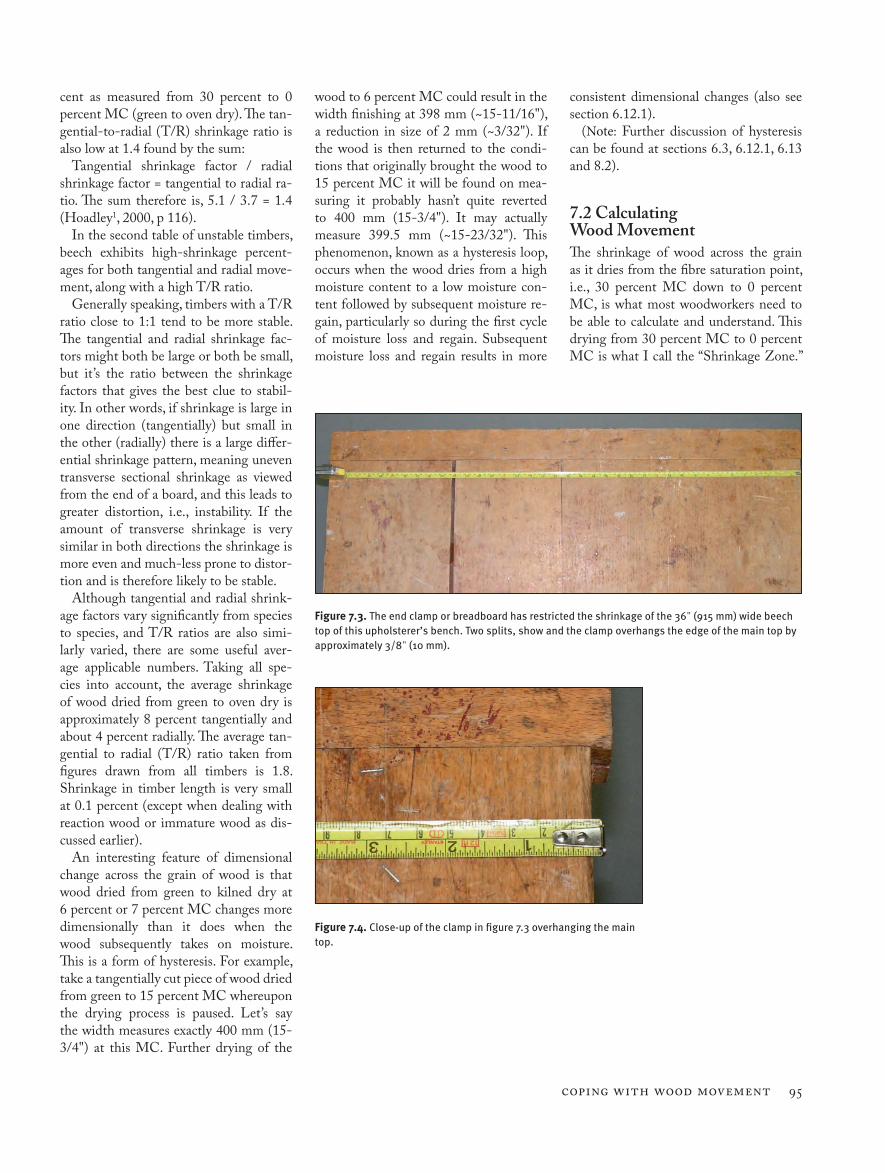
Figure 7.3. The end clamp or breadboard has restricted the shrinkage of the 36" (915 mm) wide beech top of this upholsterer’s bench. Two splits, show and the clamp overhangs the edge of the main top by approximately 3/8" (10 mm).
Figure 7.4. Close-up of the clamp in figure 7.3 overhanging the main top.
Shrinkage Factors For a Collection of Stable Woods
Wood/Timber Approx. Percentage Shrinkage from Green to 0 Percent MC
Ratio of Tangenial to Radial Shrinkage, (T/R)
Tangenial Radial
Mesquite, e.g., Pro-sopis glandulosa and Pjuliflora aka Texas Ironwood
2.6 2.2 1.1
Mahogany, Ameri-can, Swietenia macrophylla.
5.1 3.7 1.4
Greenheart, Ocotea rodiaei
9 8.2 1.1
Hop-hornbeam, British English; Hophornbeam, U.S., Ostrya carpinifolia. Sometimes known as ironwood.
10 9 1.1
Shrinkage Factors For a Collection of Unstable Woods
Wood/Timber Approx. Percentage Shrinkage from Green to 0 Percent MC
Ratio of Tangenial to Radial Shrinkage, (T/R)
Tangenial Radial
Lauan, Shorea contorta
8 3.8 2.1
Keruing, Dipterocarpus soo.
10.9 5.2 2.1
Oak, Northern Red, U.S., Quercus rubra (aka Quercus borea-lis)
8.6 4 2.2
Beech European, Fagus sylvatica
10.7 5.8 2.2
Madrone, Pacific, Arbutus menziesii
12.4 5.6 2.2
Elm, American, Ul-mus americana
9.5 4.2 2.3
Oak, overcup, Quercus lyrata
12.7 5.3 2.4
96 CHAPTER V11
Conversely wood expands in width as it gains moisture in the Shrinkage Zone (SZ) from 0 percent to 30 percent MC. Above 30 percent MC wood (as has al-ready been discussed) is relatively stable. Most shrinkage, expansion and distortion of wood occurs within the SZ (Shrinkage Zone).
Dimensional change across the grain as wood dries or moistens, both tangentially
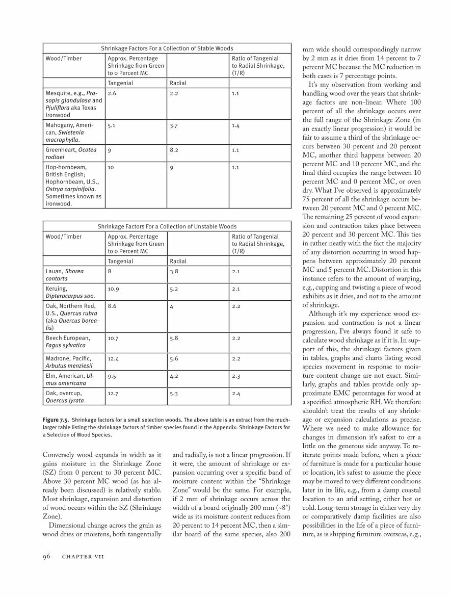
Figure 7.5. Shrinkage factors for a small selection woods. The above table is an extract from the much-larger table listing the shrinkage factors of timber species found in the Appendix: Shrinkage Factors for a Selection of Wood Species.
and radially, is not a linear progression. If it were, the amount of shrinkage or ex-pansion occurring over a specific band of moisture content within the “Shrinkage Zone” would be the same. For example, if 2 mm of shrinkage occurs across the width of a board originally 200 mm (~8") wide as its moisture content reduces from 20 percent to 14 percent MC, then a sim-ilar board of the same species, also 200
mm wide should correspondingly narrow by 2 mm as it dries from 14 percent to 7 percent MC because the MC reduction in both cases is 7 percentage points.
It’s my observation from working and handling wood over the years that shrink-age factors are non-linear. Where 100 percent of all the shrinkage occurs over the full range of the Shrinkage Zone (in an exactly linear progression) it would be fair to assume a third of the shrinkage oc-curs between 30 percent and 20 percent MC, another third happens between 20 percent MC and 10 percent MC, and the final third occupies the range between 10 percent MC and 0 percent MC, or oven dry. What I’ve observed is approximately 75 percent of all the shrinkage occurs be-tween 20 percent MC and 0 percent MC. The remaining 25 percent of wood expan-sion and contraction takes place between 20 percent and 30 percent MC. This ties in rather neatly with the fact the majority of any distortion occurring in wood hap-pens between approximately 20 percent MC and 5 percent MC. Distortion in this instance refers to the amount of warping, e.g., cupping and twisting a piece of wood exhibits as it dries, and not to the amount of shrinkage.
Although it’s my experience wood ex-pansion and contraction is not a linear progression, I’ve always found it safe to calculate wood shrinkage as if it is. In sup-port of this, the shrinkage factors given in tables, graphs and charts listing wood species movement in response to mois-ture content change are not exact. Simi-larly, graphs and tables provide only ap-proximate EMC percentages for wood at a specified atmospheric RH. We therefore shouldn’t treat the results of any shrink-age or expansion calculations as precise. Where we need to make allowance for changes in dimension it’s safest to err a little on the generous side anyway. To re-iterate points made before, when a piece of furniture is made for a particular house or location, it’s safest to assume the piece may be moved to very different conditions later in its life, e.g., from a damp coastal location to an arid setting, either hot or cold. Long-term storage in either very dry or comparatively damp facilities are also possibilities in the life of a piece of furni-ture, as is shipping furniture overseas, e.g.,
Coping with Wood Movement 97
a family moving from the relatively damp west coast of the British Isles to hot and dry Arizona.
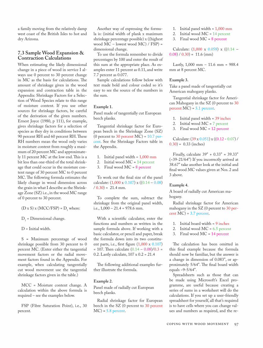
7.3 Sample Wood Expansion & Contraction CalculationsWhen estimating the likely dimensional change in a piece of wood in service I al-ways use 0 percent to 30 percent change in MC as the basis for calculations. The amount of shrinkage given in the wood expansion and contraction table in the Appendix: Shrinkage Factors for a Selec-tion of Wood Species relate to this range of moisture content. If you use other sources for shrinkage factors, be careful of the derivation of the given numbers. Ernest Joyce (1980, p 111), for example, gives shrinkage factors for a selection of species as they dry in conditions between 90 percent RH and 60 percent RH. These RH numbers mean the wood only varies in moisture content from roughly a maxi-mum of 20 percent MC and approximate-ly 11 percent MC at the low end. This is a bit less than one-third of the total shrink-age that could occur in the moisture con-tent range of 30 percent MC to 0 percent MC. The following formula estimates the likely change in wood dimension across the grain in what I describe as the Shrink-age Zone (SZ) i.e., in the wood MC range of 0 percent to 30 percent.
(D x S) x (MCC/FSP) = D1 where:
D1 = Dimensional change.
D = Initial width.
S = Maximum percentage of wood shrinkage possible from 30 percent to 0 percent MC. (Enter either the tangential movement factors or the radial move-ment factors found in the Appendix. For example, when calculating tangentially cut wood movement use the tangential shrinkage factors given in the table.)
MCC = Moisture content change. A calculation within the above formula is required – see the examples below.
FSP (Fibre Saturation Point), i.e., 30 percent.
Another way of expressing the formu-la is: (initial width of plank x maximum shrinkage percentage possible) x ((highest wood MC – lowest wood MC) / FSP) = dimensional change.
To use the formula remember to divide percentages by 100 and enter the result of this sum at the appropriate place. As ex-amples enter 11 percent as 0.11, and write 7.7 percent as 0.077.
Sample calculations follow below with text made bold and colour coded so it’s easy to see the source of the numbers in the sum.
Example 1.Panel made of tangentially cut European beech planks.
Tangential shrinkage factor for Euro-pean beech in the Shrinkage Zone (SZ) (0 percent to 30 percent MC) = 10.7 per-cent. See the Shrinkage Factors table in the Appendix.
1. Initial panel width = 1,000 mm2. Initial wood MC = 14 percent3. Final wood MC = 8 percent
To work out the final size of the panel calculate: (1,000 x 0.107) x ((0.14 – 0.08) / 0.30) = 21.4 mm.
To complete the sum, subtract the shrinkage from the original panel width, i.e., 1,000 – 21.4 = 978.6 mm.
With a scientific calculator, enter the functions and numbers as written in the sample formula above. If working with a basic calculator, or pencil and paper, break the formula down into its two constitu-ent parts, i.e., first figure (1,000 x 0.107) = 107. Then calculate (0.14 – 0.08)/0.3 = 0.2. Lastly calculate, 107 x 0.2 = 21.4
The following additional examples fur-ther illustrate the formula.
Example 2.Panel made of radially cut European beech planks.
Radial shrinkage factor for European beech in the SZ (0 percent to 30 percent MC) = 5.8 percent.
1. Initial panel width = 1,000 mm2. Initial wood MC = 14 percent3. Final wood MC = 8 percent
Calculate: (1,000 x 0.058) x ((0.14 – 0.08) / 0.30) = 11.6 (mm)
Lastly, 1,000 mm – 11.6 mm = 988.4 mm at 8 percent MC.
Example 3.Take a panel made of tangentially cut American mahogany planks.
Tangential shrinkage factor for Ameri-can Mahogany in the SZ (0 percent to 30 percent MC) = 5.1 percent.
1. Initial panel width = 39 inches2. Initial wood MC = 7 percent3. Final wood MC = 12 percent
Calculate: (39 x 0.051) x ((0.12 - 0.07) / 0.30) = 0.33 (inches)
Finally, calculate 39" + 0.33" = 39.33" (~39-21/64") If you incorrectly arrived at 38.67" take another look at the initial and final wood MC values given at Nos. 2 and 3 above.
Example 4.A board of radially cut American ma-hogany.
Radial shrinkage factor for American mahogany in the SZ (0 percent to 30 per-cent MC) = 3.7 percent.
1. Initial board width = 9 inches2. Initial wood MC = 6.5 percent3. Final wood MC = 14 percent
The calculation has been omitted in this final example because the formula should now be familiar, but the answer is a change in dimension of 0.083", or ap-proximately 5/64". The final board width equals ~9-5/64".
Spreadsheets such as those that can be made using Microsoft’s Excel pro-gramme, are useful because creating a series of sums in a worksheet will do the calculations. If you set up a user-friendly spreadsheet for yourself, all that’s required is to have cells where you can change val-ues and numbers as required, and the re-
98 CHAPTER V11
sults can help a maker come to technical and design decisions.
Once you’ve understood the general principles of wood movement in response to changes in atmospheric RH, the knowledge has applications in a range of circumstances. For example, you can build furniture and make allowance for seasonal dimensional changes of the material in re-sponse to seasonal changes in RH.
A realistic scenario is to take a look at an American white oak panel finished on all faces and edges with a film-forming polish such as lacquer or varnish. Polishes form a partial barrier to water vapour and slow down the rate of moisture exchange between the wood and the surrounding air, although they don’t stop it. The wood will move, but the polish barrier will ex-tend the natural hysteresis (delayed reac-tion to altered conditions) of wood even further. Let’s say the panel forms part of a piece of furniture in a British house. In late October it’s MC, checked with a moisture meter, reads 11 percent.
This moisture content is about right for the time of year. Internal RH figures for a typical British house shows average RH at that time of year is typically 55 per-cent or 60 percent. Fifty-five percent RH equates to a wood EMC of roughly 10.5 percent.
August through October are the months when RH is highest in British houses. The driest month is March, when RH hovers close to 40 percent RH. As autumn and winter progress, the wood will gradually dry out to approximately 7.5 percent MC. All that is required now to create calcu-lations like the ones shown earlier is to calculate changes in panel width. Let’s say the panel width is 410 mm. The maximum movement factors for American white oak are 10.5 percent tangentially cut and 5.6 percent radially cut.
Let’s also say the panel is made of four boards just over 100 mm wide. Each board shows roughly equal amounts of radially cut and tangentially cut wood as seen by looking at the end grain. The amount of dimensional change that will therefore occur will be approximately in the middle of the range between the 10.5 percent tangential movement and the 5.6 percent radial movement attributable to American white oak, i.e., ~8.05 percent.
The calculation is: (410 mm x 0.0805) x ((0.11 - 0.075) / 0.30) = 3.85 mm. The panel width will vary between about 406 mm during the late spring and expand back to approximately 410 mm by mid to late autumn.
Applying calculations such as these are useful prior to and during construction of furniture in the workshop. If you know the moisture content of the wood purchased for a job, and know roughly the RH value of your workshop or storage facility at the time you store or work the wood, you can calculate several useful numbers. You can work out what MC your wood will fin-ish at over a given period if your pile is stickered up, allowing air to circulate. This might suggest you slow down the move-ment of moisture into or out of the wood by close stacking the pile to prevent air circulating freely.16
You can calculate the likely dimensional change of your wood over time within the workshop as you work it. And you can make educated assessments of the likely dimensional change of wood after deliv-ery of the piece of furniture to your cus-tomer. For example, if during the period when the furniture is made, the wood has an initial MC of 10 percent and the RH in your workshop hovers around 60 per-cent, and you know the final destination of your piece is a strictly climate-controlled museum where RH is kept constant at 35 percent MC, it almost certainly makes sense to fit traditional handmade dove-tailed drawers guided by runners and kickers just a little tight – the drawers will shrink in height in service.
Built-in furniture attached to the wall can justifiably use man-made board for the plinth or toe kick. A solid-wood board attached with screws in sloppy holes to the front of the plywood plinth makes a durable and attractive face. It al-lows for wood movement and works well. Man-made board is dimensionally stable compared to solid wood, and using it for a plinth means the top of the cabinet stays at the same height all the time. On the other hand, a 6" (150 mm) wide solid English oak plinth with the grain running horizontally expands and contracts ap-proximately 3 mm (1/8") if the moisture content of the wood changes seasonally by the quite large amount of 7 percent,
e.g., from 5 percent to 12 percent MC, or 7 percent to 14 percent MC. This move-ment doesn’t seem much, but if the plinth supports a wooden bathroom sink unit above which an “upstand”, aka backsplash, is attached to the wall, then the potential for a gap forming is obvious.
Similar assessments or calculations are useful if you’re making traditional solid-wood drawers guided by runners and kickers, which are the horizontal frames built into a carcase. Some workers aim for what’s often called a “piston fit” drawer, which is basically a drawer with very little side-to-side or top-to-bottom tolerance within the drawer opening. It could be the case that one or more drawers in a cabinet is, or are, very tall requiring wide pieces of wood for the drawer front, sides and back, perhaps 200 mm to 250 mm wide (8" to 10"). This suggests a drawer made out of wood at 7 percent MC fitted to its opening with little or no vertical tolerance during winter in a climate-controlled workshop in Britain will swell and in all likelihood jam during late summer or au-tumn. It’s difficult to make a tall, close-tolerance “piston fit” drawer that will work as intended all through the year. If the drawer is made to work as a piston fit item during autumn months then, by the following spring, after the wood shrinks it will be somewhat sloppy. This, though, is preferable to a drawer which is piston fit during the late British winter or early spring but swells and sticks in the summer and autumn.
7.4 Distortion – Warping, Cupping, Bowing etc.Apart from the expansion and contrac-tion of wood, particularly across the grain, woodworkers must take into account that there are many and varied ways wood movement can cause problems. For ex-ample, there are differential shrinkage factors between radially cut and tangen-tially cut boards of the same species. Join-ing radially cut planks to tangentially cut planks to make a panel usually results in ridges at the join lines. There are problems that occur when released stresses affect a board, such as cupping, bowing and wind-ing, aka twisting. Frame-and-panel doors are more likely to warp when the framing
Coping with Wood Movement 99
is made of tangentially sawn wood com-pared to using radially cut material. Sur-face checking caused by improper drying of the wood may be invisible during con-struction of a piece of furniture, but due to shrinkage reveals itself after the piece goes into service.
Warp is the result of differential shrink-age between opposite faces of a board or, similarly, differential shrinkage between opposite edges of a board. The result is cup, bow, crook or winding – these are not the only terms used to describe various forms of warp, and alternative terms are intro-duced in the following text. Where there occurs differential shrinkage in more than one plane, a single plank might exhibit all the faults, i.e., it’s cupped, bowed, crooked and twisted or “in winding.”
Illustrated at figures 7.7 and 7.8 are the
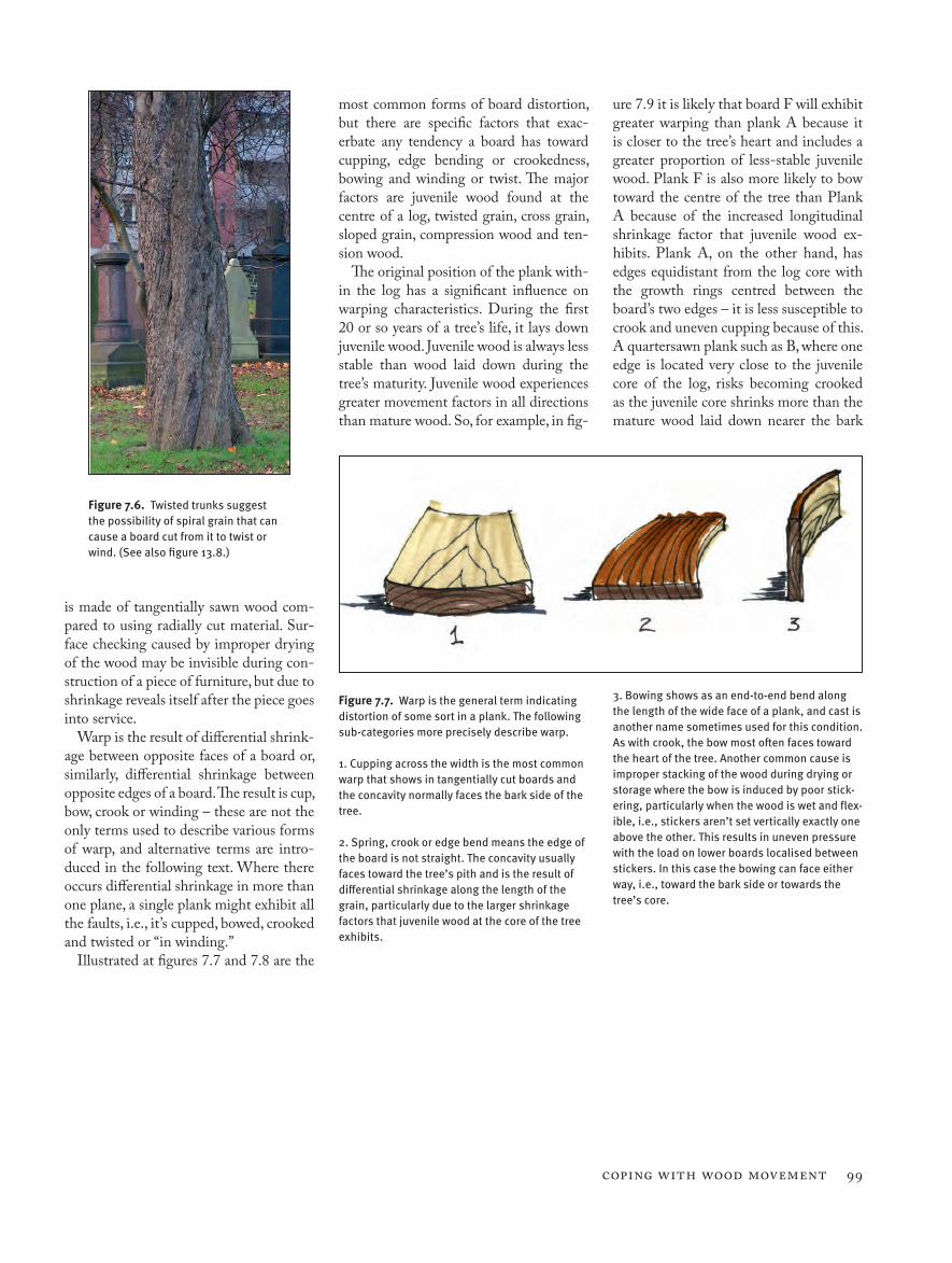
Figure 7.6. Twisted trunks suggest the possibility of spiral grain that can cause a board cut from it to twist or wind. (See also figure 13.8.)
most common forms of board distortion, but there are specific factors that exac-erbate any tendency a board has toward cupping, edge bending or crookedness, bowing and winding or twist. The major factors are juvenile wood found at the centre of a log, twisted grain, cross grain, sloped grain, compression wood and ten-sion wood.
The original position of the plank with-in the log has a significant influence on warping characteristics. During the first 20 or so years of a tree’s life, it lays down juvenile wood. Juvenile wood is always less stable than wood laid down during the tree’s maturity. Juvenile wood experiences greater movement factors in all directions than mature wood. So, for example, in fig-
ure 7.9 it is likely that board F will exhibit greater warping than plank A because it is closer to the tree’s heart and includes a greater proportion of less-stable juvenile wood. Plank F is also more likely to bow toward the centre of the tree than Plank A because of the increased longitudinal shrinkage factor that juvenile wood ex-hibits. Plank A, on the other hand, has edges equidistant from the log core with the growth rings centred between the board’s two edges – it is less susceptible to crook and uneven cupping because of this. A quartersawn plank such as B, where one edge is located very close to the juvenile core of the log, risks becoming crooked as the juvenile core shrinks more than the mature wood laid down nearer the bark
Figure 7.7. Warp is the general term indicating distortion of some sort in a plank. The following sub-categories more precisely describe warp. 1. Cupping across the width is the most common warp that shows in tangentially cut boards and the concavity normally faces the bark side of the tree. 2. Spring, crook or edge bend means the edge of the board is not straight. The concavity usually faces toward the tree’s pith and is the result of differential shrinkage along the length of the grain, particularly due to the larger shrinkage factors that juvenile wood at the core of the tree exhibits.
3. Bowing shows as an end-to-end bend along the length of the wide face of a plank, and cast is another name sometimes used for this condition. As with crook, the bow most often faces toward the heart of the tree. Another common cause is improper stacking of the wood during drying or storage where the bow is induced by poor stick-ering, particularly when the wood is wet and flex-ible, i.e., stickers aren’t set vertically exactly one above the other. This results in uneven pressure with the load on lower boards localised between stickers. In this case the bowing can face either way, i.e., toward the bark side or towards the tree’s core.
100 CHAPTER V11
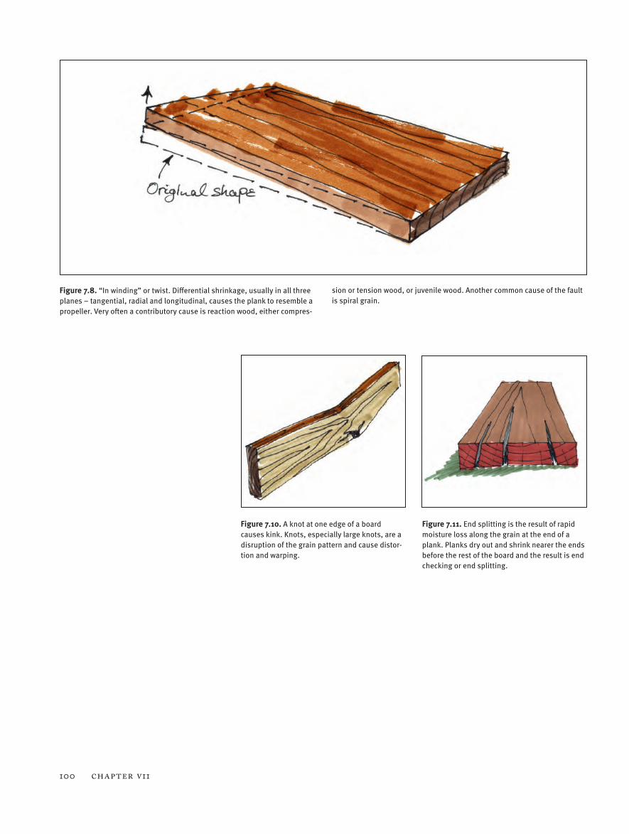
Figure 7.8. “In winding” or twist. Differential shrinkage, usually in all three planes – tangential, radial and longitudinal, causes the plank to resemble a propeller. Very often a contributory cause is reaction wood, either compres-
sion or tension wood, or juvenile wood. Another common cause of the fault is spiral grain.
Figure 7.11. End splitting is the result of rapid moisture loss along the grain at the end of a plank. Planks dry out and shrink nearer the ends before the rest of the board and the result is end checking or end splitting.
Figure 7.10. A knot at one edge of a board causes kink. Knots, especially large knots, are a disruption of the grain pattern and cause distor-tion and warping.
Coping with Wood Movement 101
Figure 7.12. End splitting in air-dried English oak.
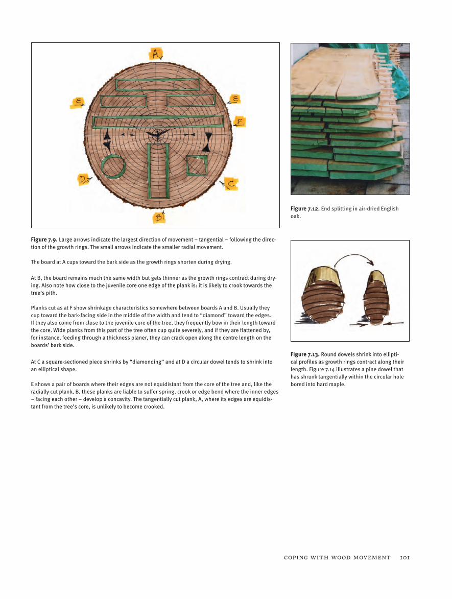
Figure 7.9. Large arrows indicate the largest direction of movement – tangential – following the direc-tion of the growth rings. The small arrows indicate the smaller radial movement. The board at A cups toward the bark side as the growth rings shorten during drying. At B, the board remains much the same width but gets thinner as the growth rings contract during dry-ing. Also note how close to the juvenile core one edge of the plank is: it is likely to crook towards the tree’s pith. Planks cut as at F show shrinkage characteristics somewhere between boards A and B. Usually they cup toward the bark-facing side in the middle of the width and tend to “diamond” toward the edges. If they also come from close to the juvenile core of the tree, they frequently bow in their length toward the core. Wide planks from this part of the tree often cup quite severely, and if they are flattened by, for instance, feeding through a thickness planer, they can crack open along the centre length on the boards’ bark side.
At C a square-sectioned piece shrinks by “diamonding” and at D a circular dowel tends to shrink into an elliptical shape. E shows a pair of boards where their edges are not equidistant from the core of the tree and, like the radially cut plank, B, these planks are liable to suffer spring, crook or edge bend where the inner edges – facing each other – develop a concavity. The tangentially cut plank, A, where its edges are equidis-tant from the tree’s core, is unlikely to become crooked.
Figure 7.13. Round dowels shrink into ellipti-cal profiles as growth rings contract along their length. Figure 7.14 illustrates a pine dowel that has shrunk tangentially within the circular hole bored into hard maple.
102 CHAPTER V11
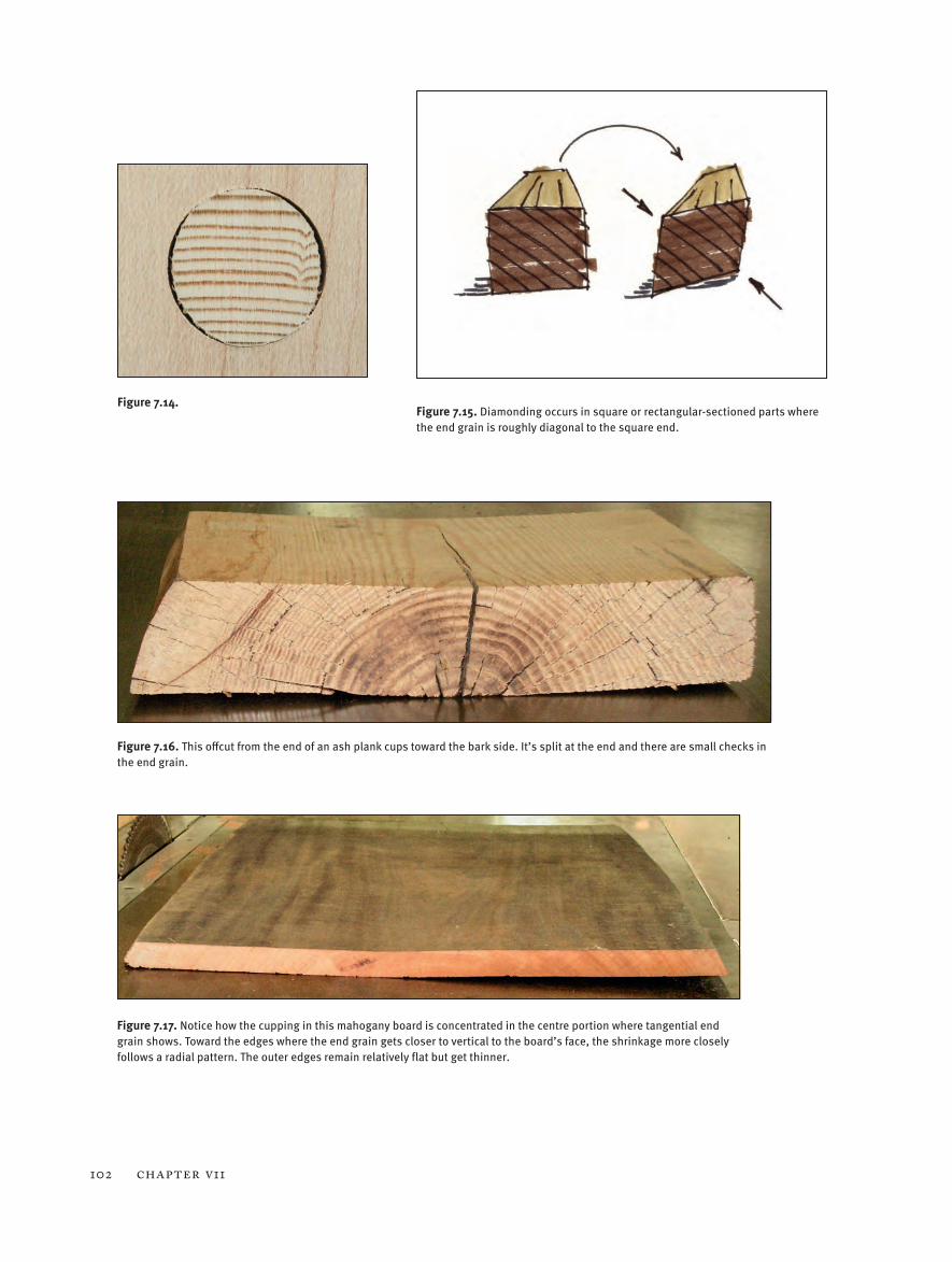
Figure 7.16. This offcut from the end of an ash plank cups toward the bark side. It’s split at the end and there are small checks in the end grain.
Figure 7.14. Figure 7.15. Diamonding occurs in square or rectangular-sectioned parts where the end grain is roughly diagonal to the square end.
Figure 7.17. Notice how the cupping in this mahogany board is concentrated in the centre portion where tangential end grain shows. Toward the edges where the end grain gets closer to vertical to the board’s face, the shrinkage more closely follows a radial pattern. The outer edges remain relatively flat but get thinner.
Coping with Wood Movement 103
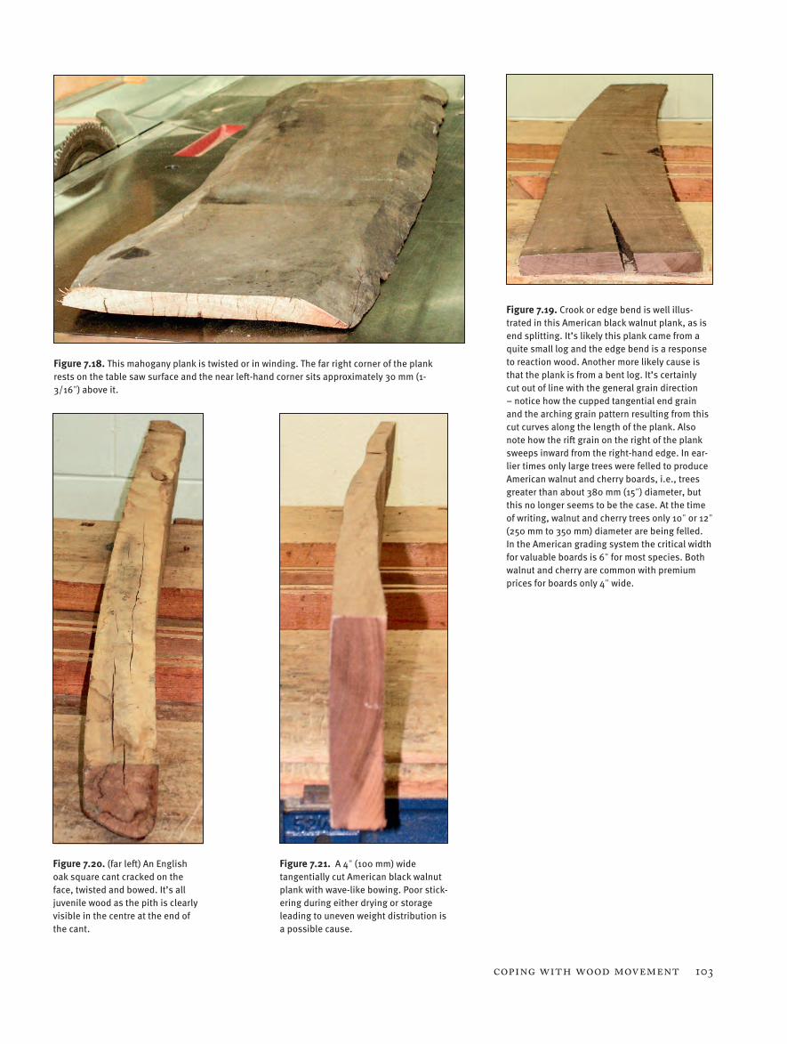
Figure 7.18. This mahogany plank is twisted or in winding. The far right corner of the plank rests on the table saw surface and the near left-hand corner sits approximately 30 mm (1-3/16") above it.
Figure 7.19. Crook or edge bend is well illus-trated in this American black walnut plank, as is end splitting. It’s likely this plank came from a quite small log and the edge bend is a response to reaction wood. Another more likely cause is that the plank is from a bent log. It’s certainly cut out of line with the general grain direction – notice how the cupped tangential end grain and the arching grain pattern resulting from this cut curves along the length of the plank. Also note how the rift grain on the right of the plank sweeps inward from the right-hand edge. In ear-lier times only large trees were felled to produce American walnut and cherry boards, i.e., trees greater than about 380 mm (15") diameter, but this no longer seems to be the case. At the time of writing, walnut and cherry trees only 10" or 12" (250 mm to 350 mm) diameter are being felled. In the American grading system the critical width for valuable boards is 6" for most species. Both walnut and cherry are common with premium prices for boards only 4" wide.
Figure 7.20. (far left) An English oak square cant cracked on the face, twisted and bowed. It’s all juvenile wood as the pith is clearly visible in the centre at the end of the cant.
Figure 7.21. A 4" (100 mm) wide tangentially cut American black walnut plank with wave-like bowing. Poor stick-ering during either drying or storage leading to uneven weight distribution is a possible cause.
104 CHAPTER V11
of the tree.Boarding or planking up small logs
causes more warping than planking up large logs because of the greater propor-tion of juvenile wood in a small log. Cut-ting boards out of crooked logs, boards cut around a large branch, and sawing boards at a marked angle to the grain direction
in the log all cause problems. The appear-ance and patterns may be attractive, but these cuts produce planks where the grain is short, runs out sharply on one face or edge, or the grain reverses: all these pat-terns increase the likelihood of instability leading to warping.
7.5 Wood Movement & JoineryMaking furniture throws up all sorts of interesting construction quandaries for the furniture maker. For instance the di-mensional changes and distortions that are sometimes barely noticeable or impor-tant in a single piece of wood can lead to
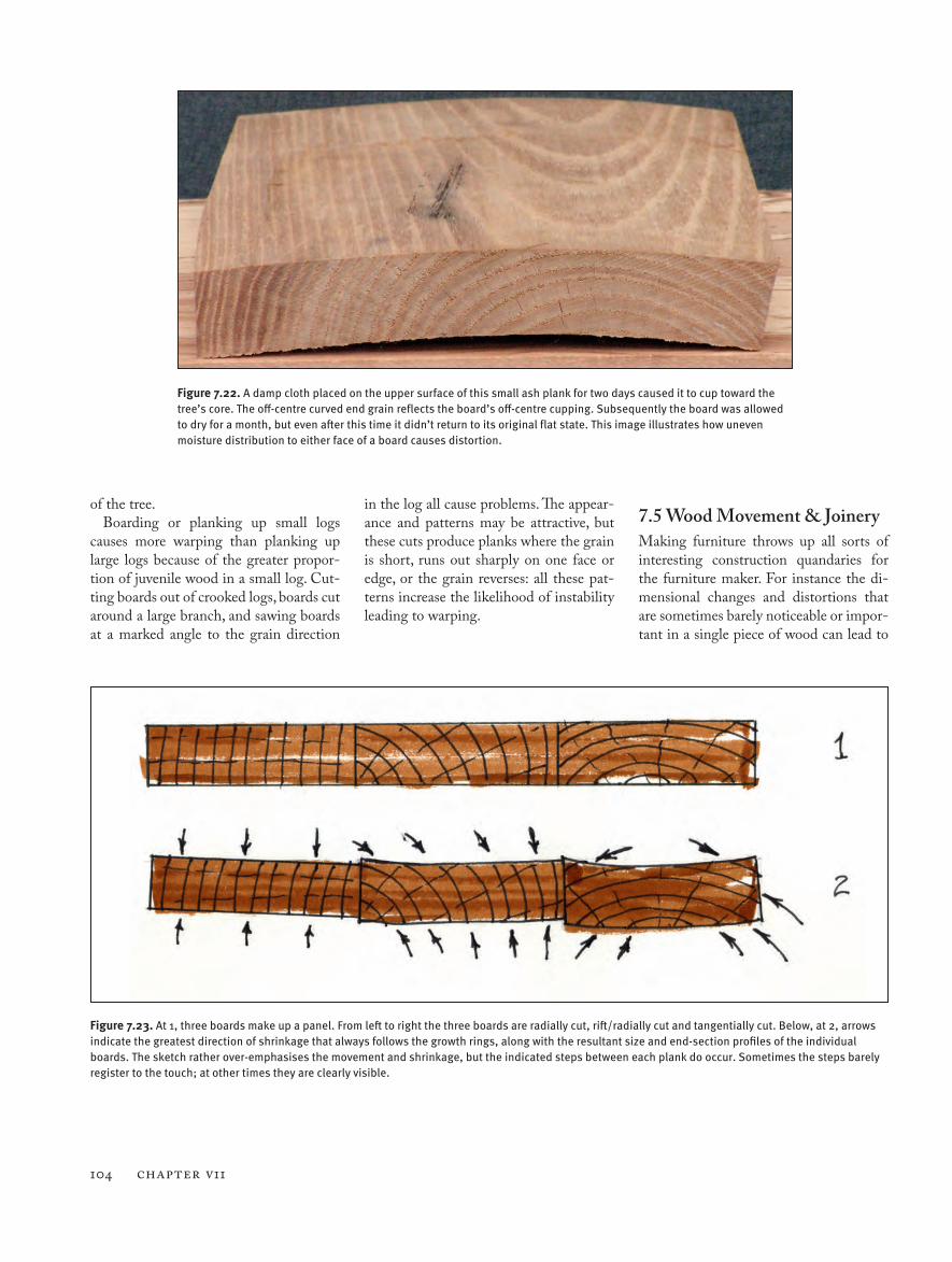
Figure 7.22. A damp cloth placed on the upper surface of this small ash plank for two days caused it to cup toward the tree’s core. The off-centre curved end grain reflects the board’s off-centre cupping. Subsequently the board was allowed to dry for a month, but even after this time it didn’t return to its original flat state. This image illustrates how uneven moisture distribution to either face of a board causes distortion.
Figure 7.23. At 1, three boards make up a panel. From left to right the three boards are radially cut, rift/radially cut and tangentially cut. Below, at 2, arrows indicate the greatest direction of shrinkage that always follows the growth rings, along with the resultant size and end-section profiles of the individual boards. The sketch rather over-emphasises the movement and shrinkage, but the indicated steps between each plank do occur. Sometimes the steps barely register to the touch; at other times they are clearly visible.
Coping with Wood Movement 105
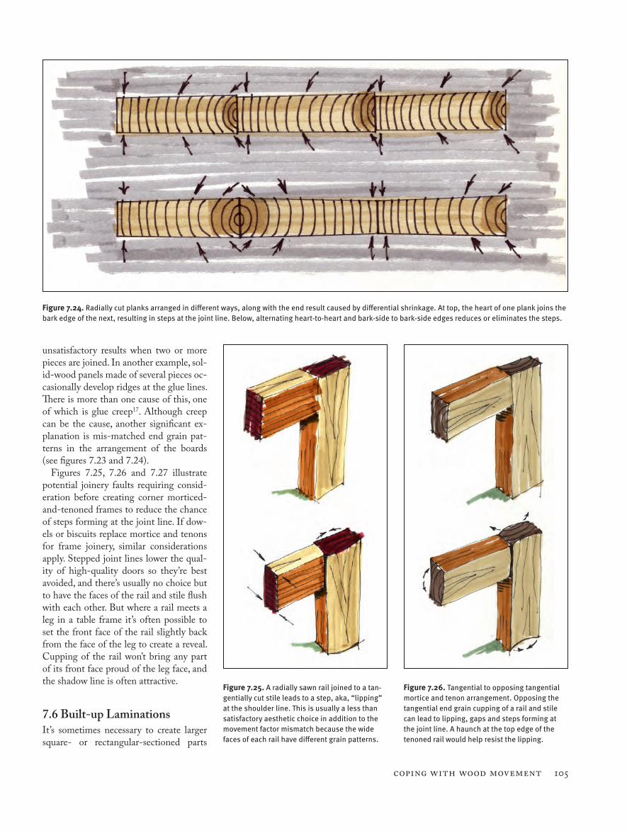
Figure 7.24. Radially cut planks arranged in different ways, along with the end result caused by differential shrinkage. At top, the heart of one plank joins the bark edge of the next, resulting in steps at the joint line. Below, alternating heart-to-heart and bark-side to bark-side edges reduces or eliminates the steps.
Figure 7.25. A radially sawn rail joined to a tan-gentially cut stile leads to a step, aka, “lipping” at the shoulder line. This is usually a less than satisfactory aesthetic choice in addition to the movement factor mismatch because the wide faces of each rail have different grain patterns.
Figure 7.26. Tangential to opposing tangential mortice and tenon arrangement. Opposing the tangential end grain cupping of a rail and stile can lead to lipping, gaps and steps forming at the joint line. A haunch at the top edge of the tenoned rail would help resist the lipping.
unsatisfactory results when two or more pieces are joined. In another example, sol-id-wood panels made of several pieces oc-casionally develop ridges at the glue lines. There is more than one cause of this, one of which is glue creep17. Although creep can be the cause, another significant ex-planation is mis-matched end grain pat-terns in the arrangement of the boards (see figures 7.23 and 7.24).
Figures 7.25, 7.26 and 7.27 illustrate potential joinery faults requiring consid-eration before creating corner morticed-and-tenoned frames to reduce the chance of steps forming at the joint line. If dow-els or biscuits replace mortice and tenons for frame joinery, similar considerations apply. Stepped joint lines lower the qual-ity of high-quality doors so they’re best avoided, and there’s usually no choice but to have the faces of the rail and stile flush with each other. But where a rail meets a leg in a table frame it’s often possible to set the front face of the rail slightly back from the face of the leg to create a reveal. Cupping of the rail won’t bring any part of its front face proud of the leg face, and the shadow line is often attractive.
7.6 Built-up LaminationsIt’s sometimes necessary to create larger square- or rectangular-sectioned parts
106 CHAPTER V11
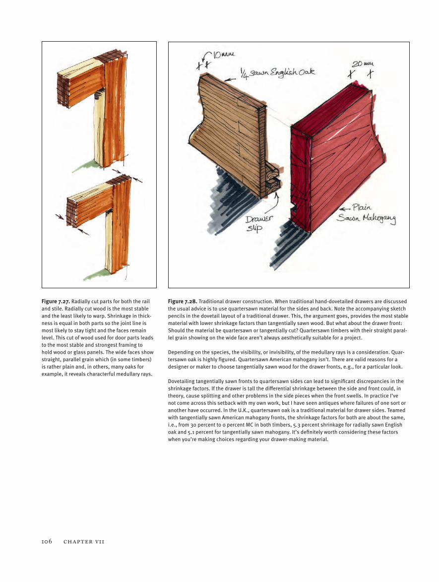
Figure 7.27. Radially cut parts for both the rail and stile. Radially cut wood is the most stable and the least likely to warp. Shrinkage in thick-ness is equal in both parts so the joint line is most likely to stay tight and the faces remain level. This cut of wood used for door parts leads to the most stable and strongest framing to hold wood or glass panels. The wide faces show straight, parallel grain which (in some timbers) is rather plain and, in others, many oaks for example, it reveals characterful medullary rays.
Figure 7.28. Traditional drawer construction. When traditional hand-dovetailed drawers are discussed the usual advice is to use quartersawn material for the sides and back. Note the accompanying sketch pencils in the dovetail layout of a traditional drawer. This, the argument goes, provides the most stable material with lower shrinkage factors than tangentially sawn wood. But what about the drawer front: Should the material be quartersawn or tangentially cut? Quartersawn timbers with their straight paral-lel grain showing on the wide face aren’t always aesthetically suitable for a project. Depending on the species, the visibility, or invisibility, of the medullary rays is a consideration. Quar-tersawn oak is highly figured. Quartersawn American mahogany isn’t. There are valid reasons for a designer or maker to choose tangentially sawn wood for the drawer fronts, e.g., for a particular look. Dovetailing tangentially sawn fronts to quartersawn sides can lead to significant discrepancies in the shrinkage factors. If the drawer is tall the differential shrinkage between the side and front could, in theory, cause splitting and other problems in the side pieces when the front swells. In practice I’ve not come across this setback with my own work, but I have seen antiques where failures of one sort or another have occurred. In the U.K., quartersawn oak is a traditional material for drawer sides. Teamed with tangentially sawn American mahogany fronts, the shrinkage factors for both are about the same, i.e., from 30 percent to 0 percent MC in both timbers, 5.3 percent shrinkage for radially sawn English oak and 5.1 percent for tangentially sawn mahogany. It’s definitely worth considering these factors when you’re making choices regarding your drawer-making material.
Coping with Wood Movement 107
out of smaller pieces. A typical scenario is a need for something like 85 mm (3-3/8") square section stuff for table leg blanks later shaped, profiled or turned. If 100 mm (4") thick rough-sawn wood isn’t available, two pieces of 50 mm (2") thick stuff can often substitute. Ma-chine up two pieces of wood the required length, about 90 mm (3-1/2") wide by 46 mm (~1-13/16") thick, and glue the wide faces together. Similarly there are many woodworkers who build a workbench for themselves and want a 3" to 4" (75 mm to 100 mm) thick top of beech or maple. The only way this is normally achievable is to glue together the 3" to 4" (75 mm to 100 mm) wide faces of several 1" to 2" (25 mm to 50 mm) thick boards. In this circum-stance, one area to pay special attention to is the orientation of the growth rings at the end of each board. Where the end
grain shows every plank tangentially cut as in figure 7.30, there are arrangements that work with the natural shrinkage of the wood, and arrangements that work against this movement.
7.7 End Grain Orientation & Panel Glue-upsAt some point almost every woodworker faces the need to make wide panels out of narrow timber. There are several good reasons for edge joining narrow boards to make wide slabs.
• The selected timber is only avail-able in narrow planks.
• The machinery available can only cope with modest sizes, assuming of course stock is prepared with machinery rather than hand tools.
• It may be that cutting wide pieces
into smaller sections and rearrang-ing the order uses the grain more attractively.
• Edge joining narrow planks some-times provides a means for control-ling, predicting and (to some extent) reducing the effects of warping.
• Preparing a long and/or wide board to a specified thickness might be impossible, i.e., getting a warped piece flat where both sides are par-allel leaves the material too thin for the job.
Some movement of joined panels will almost certainly happen due to variations in atmospheric RH. This applies to both air- and kiln-dried timber.
How you should arrange the planks is often a subject for heated debate. I use all the layouts illustrated in figures 7.31, 7.32 and 7.33, and it depends on the circum-stance. For instance, the most attractive grain might all be on either the heart side or the bark side of tangentially cut boards, and if I’m making a tabletop I will use the material this way, i.e., figure 7.32. For a ta-bletop arranged thus, I usually incorporate a heavy slot-screwed bearer on the under-side. Similarly, if a cabinet side is housed across the grain (dadoed in the U.S.) to accept a shelf or something similar, I of-ten choose the same arrangement because then, at worst, I only have a wide cupped piece to hold flat on the workbench prior to running over it with the router. This is often preferable to dealing with a series of ripples. I tend to use the layout in figure 7.31 most commonly when the strips are narrow, say 50 mm or below, or in cabinets where opposite cabinet sides are linked with tenoned or dovetailed rails.
It’s also a useful option to try and ar-range all the grain so it rises toward one end when viewing the panel from the nar-row edge, although this is often not pos-sible because the grain orientation varies so much. If successfully achieved, this results in reduced tear-out when planing the final glue-up, whether by hand or ma-chine, i.e., you can plane in one direction without tear-out. Sometimes sacrificing this consideration over appearance is a valid choice.
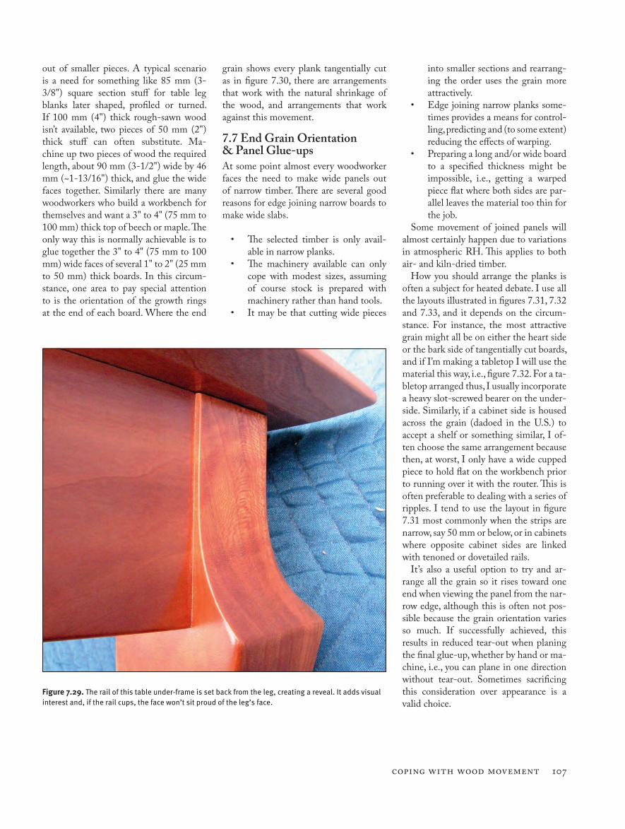
Figure 7.29. The rail of this table under-frame is set back from the leg, creating a reveal. It adds visual interest and, if the rail cups, the face won’t sit proud of the leg’s face.
108 CHAPTER V11
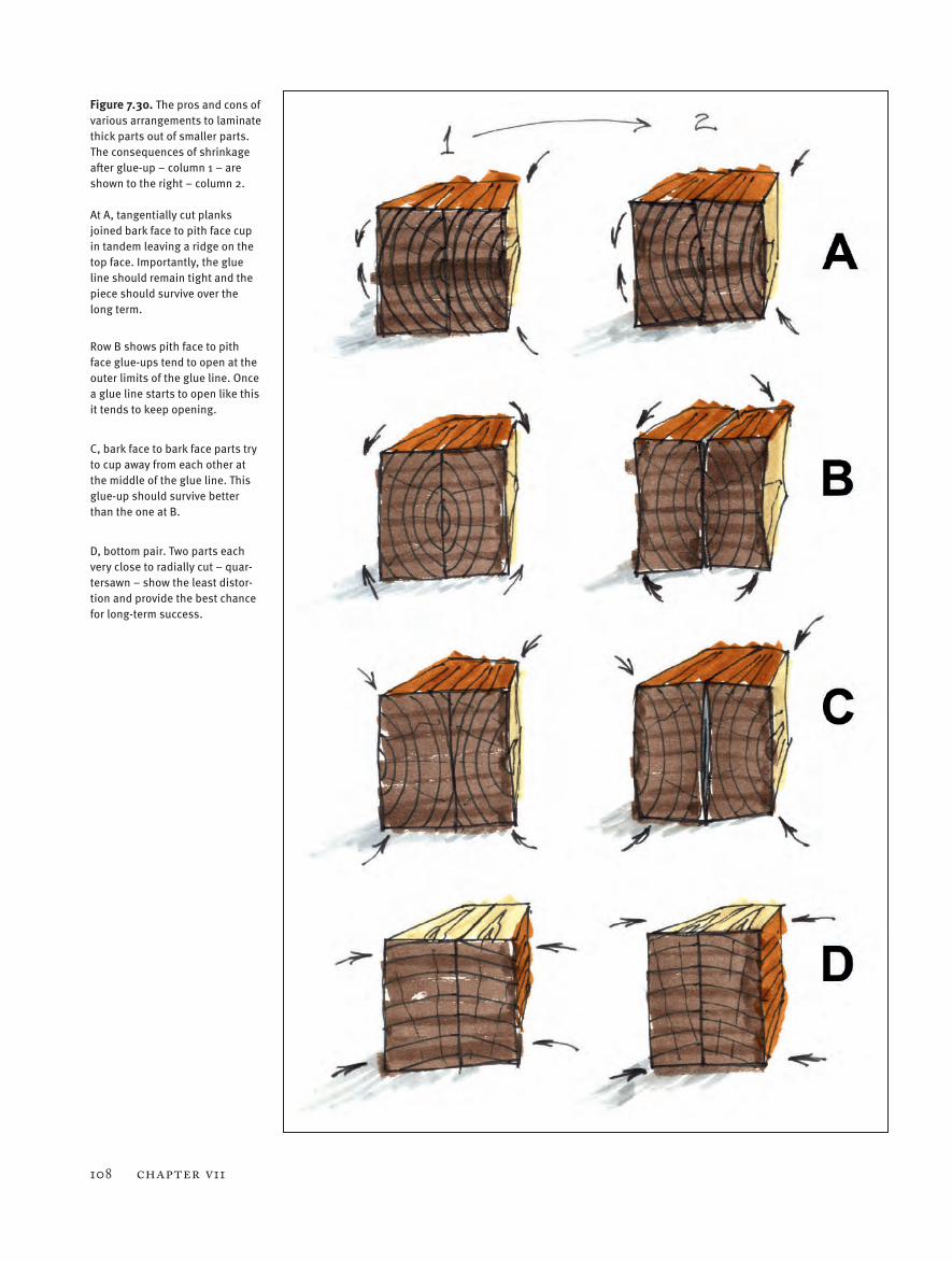
Figure 7.30. The pros and cons of various arrangements to laminate thick parts out of smaller parts. The consequences of shrinkage after glue-up – column 1 – are shown to the right – column 2. At A, tangentially cut planks joined bark face to pith face cup in tandem leaving a ridge on the top face. Importantly, the glue line should remain tight and the piece should survive over the long term.
Row B shows pith face to pith face glue-ups tend to open at the outer limits of the glue line. Once a glue line starts to open like this it tends to keep opening.
C, bark face to bark face parts try to cup away from each other at the middle of the glue line. This glue-up should survive better than the one at B.
D, bottom pair. Two parts each very close to radially cut – quar-tersawn – show the least distor-tion and provide the best chance for long-term success.
Coping with Wood Movement 109
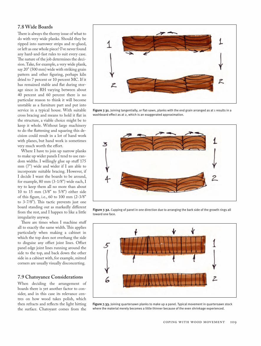
7.8 Wide BoardsThere is always the thorny issue of what to do with very wide planks. Should they be ripped into narrower strips and re-glued, or left as one whole piece? I’ve never found any hard-and-fast rules to suit every case. The nature of the job determines the deci-sion. Take, for example, a very wide plank, say 20" (500 mm) wide with striking grain pattern and other figuring, perhaps kiln dried to 7 percent or 10 percent MC. If it has remained stable and flat during stor-age since in RH varying between about 40 percent and 60 percent there is no particular reason to think it will become unstable as a furniture part and put into service in a typical house. With suitable cross bracing and means to hold it flat in the structure, a viable choice might be to keep it whole. Without large machinery to do the flattening and squaring this de-cision could result in a lot of hand work with planes, but hand work is sometimes very much worth the effort.
Where I have to join up narrow planks to make up wider panels I tend to use ran-dom widths. I willingly glue up stuff 175 mm (7") wide and wider if I am able to incorporate suitable bracing. However, if I decide I want the boards to be around, for example, 80 mm (3-1/8") wide each, I try to keep them all no more than about 10 to 15 mm (3/8" to 5/8") either side of this figure, i.e., 60 to 100 mm (2-3/8" to 3-7/8"). This tactic prevents just one board standing out as markedly different from the rest, and I happen to like a little irregularity anyway.
There are times when I machine stuff all to exactly the same width. This applies particularly when making a cabinet in which the top does not overhang the side to disguise any offset joint lines. Offset panel edge joint lines running around the side to the top, and back down the other side in a cabinet with, for example, mitred corners are usually visually disconcerting.
7.9 Chatoyance ConsiderationsWhen deciding the arrangement of boards there is yet another factor to con-sider, and in this case its relevance cen-tres on how wood takes polish, which then refracts and reflects the light hitting the surface. Chatoyant comes from the
Figure 7.31. Joining tangentially, or flat-sawn, planks with the end grain arranged as at 1 results in a washboard effect as at 2, which is an exaggerated approximation.
Figure 7.32. Cupping of panel in one direction due to arranging the bark side of the growth rings all toward one face.
Figure 7.33. Joining quartersawn planks to make up a panel. Typical movement in quartersawn stock where the material merely becomes a little thinner because of the even shrinkage experienced.
110 CHAPTER V11
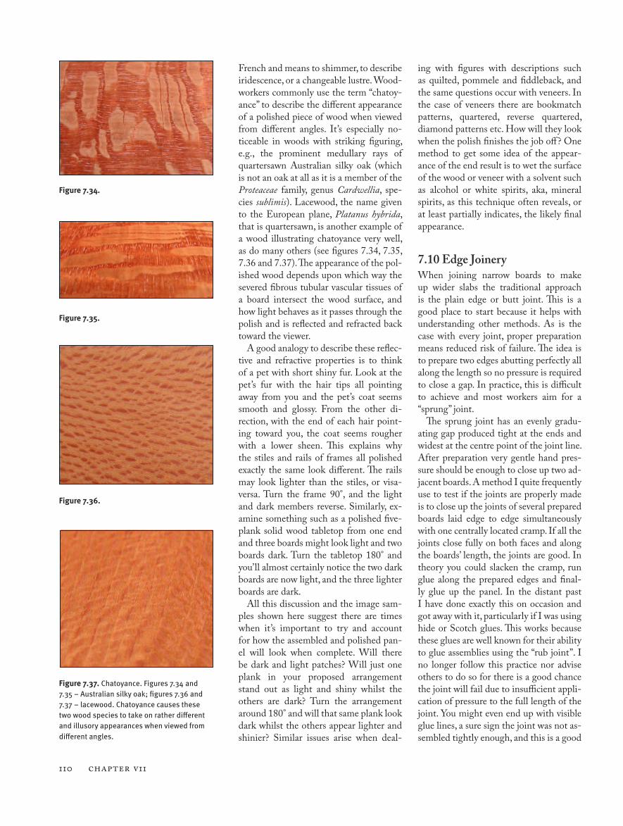
French and means to shimmer, to describe iridescence, or a changeable lustre. Wood-workers commonly use the term “chatoy-ance” to describe the different appearance of a polished piece of wood when viewed from different angles. It’s especially no-ticeable in woods with striking figuring, e.g., the prominent medullary rays of quartersawn Australian silky oak (which is not an oak at all as it is a member of the Proteaceae family, genus Cardwellia, spe-cies sublimis). Lacewood, the name given to the European plane, Platanus hybrida, that is quartersawn, is another example of a wood illustrating chatoyance very well, as do many others (see figures 7.34, 7.35, 7.36 and 7.37). The appearance of the pol-ished wood depends upon which way the severed fibrous tubular vascular tissues of a board intersect the wood surface, and how light behaves as it passes through the polish and is reflected and refracted back toward the viewer.
A good analogy to describe these reflec-tive and refractive properties is to think of a pet with short shiny fur. Look at the pet’s fur with the hair tips all pointing away from you and the pet’s coat seems smooth and glossy. From the other di-rection, with the end of each hair point-ing toward you, the coat seems rougher with a lower sheen. This explains why the stiles and rails of frames all polished exactly the same look different. The rails may look lighter than the stiles, or visa-versa. Turn the frame 90°, and the light and dark members reverse. Similarly, ex-amine something such as a polished five-plank solid wood tabletop from one end and three boards might look light and two boards dark. Turn the tabletop 180° and you’ll almost certainly notice the two dark boards are now light, and the three lighter boards are dark.
All this discussion and the image sam-ples shown here suggest there are times when it’s important to try and account for how the assembled and polished pan-el will look when complete. Will there be dark and light patches? Will just one plank in your proposed arrangement stand out as light and shiny whilst the others are dark? Turn the arrangement around 180° and will that same plank look dark whilst the others appear lighter and shinier? Similar issues arise when deal-
ing with figures with descriptions such as quilted, pommele and fiddleback, and the same questions occur with veneers. In the case of veneers there are bookmatch patterns, quartered, reverse quartered, diamond patterns etc. How will they look when the polish finishes the job off? One method to get some idea of the appear-ance of the end result is to wet the surface of the wood or veneer with a solvent such as alcohol or white spirits, aka, mineral spirits, as this technique often reveals, or at least partially indicates, the likely final appearance.
7.10 Edge JoineryWhen joining narrow boards to make up wider slabs the traditional approach is the plain edge or butt joint. This is a good place to start because it helps with understanding other methods. As is the case with every joint, proper preparation means reduced risk of failure. The idea is to prepare two edges abutting perfectly all along the length so no pressure is required to close a gap. In practice, this is difficult to achieve and most workers aim for a “sprung” joint.
The sprung joint has an evenly gradu-ating gap produced tight at the ends and widest at the centre point of the joint line. After preparation very gentle hand pres-sure should be enough to close up two ad-jacent boards. A method I quite frequently use to test if the joints are properly made is to close up the joints of several prepared boards laid edge to edge simultaneously with one centrally located cramp. If all the joints close fully on both faces and along the boards’ length, the joints are good. In theory you could slacken the cramp, run glue along the prepared edges and final-ly glue up the panel. In the distant past I have done exactly this on occasion and got away with it, particularly if I was using hide or Scotch glues. This works because these glues are well known for their ability to glue assemblies using the “rub joint”. I no longer follow this practice nor advise others to do so for there is a good chance the joint will fail due to insufficient appli-cation of pressure to the full length of the joint. You might even end up with visible glue lines, a sure sign the joint was not as-sembled tightly enough, and this is a good
Figure 7.36.
Figure 7.34.
Figure 7.35.
Figure 7.37. Chatoyance. Figures 7.34 and 7.35 – Australian silky oak; figures 7.36 and 7.37 – lacewood. Chatoyance causes these two wood species to take on rather different and illusory appearances when viewed from different angles.
Coping with Wood Movement 111
indication of probable joint failure in the future.
The sprung joint helps counteract the comparatively volatile width expansion and contraction of the last 50 mm to 100 mm (2" to 4") of a plank’s length. The end grain of timber adsorbs and gives up mois-ture the quickest. During glue up of the sprung joint, the ends are closed just a little tighter than the middle, and this helps to compensate for the disparate movement.
In addition to this, custom and practise show us that where the two joined edges are convex at glue-up the joint usually fails fairly quickly. In this situation, bringing the edges together requires firm clamping pressure at both ends to close the gap. The joint will close, but both ends of the joint are under tensile stress and want to open up. As soon as a slight opening begins at the very extremity of the joint it’s likely serious failure will soon follow – a gap of anything up to a few inches long extend-ing toward the middle of the length de-velops in just days. The worst case is com-plete failure of the joint.
The sprung joint on the other hand is much more durable. When formed cor-rectly, both ends of the joint should re-
main tight. Even with the greater vola-tility of expansion and contraction at the ends of a plank, a gap doesn’t form. I use a zip (zipper) as an analogy to explain what
goes on. Close a zip and lock the tab at the end and the zip stays closed. Pull up the zip and leave the tab unlocked and the zip gradually opens.
The basic sprung edge joint provides the largest possible matching long grain glue surfaces. If we accept the prem-ise that the strongest glue joint between two pieces of timber is long grain to long grain, then anything reducing the maxi-misation of such a joint in tabletops, pan-els etc., weakens it.
Adjoining boards in a tabletop can, and do, drift out of line in the thickness and form a step. Even the weight of a TV or computer monitor will do it with a foot placed next to a glue line and left in place for long enough. This is the case with PVA glues or the similar aliphatic resin emulsion types that creep (see this chap-ter’s endnotes).
For the reason just described, and in many other situations, many woodwork-ers like to include an alignment aid or re-inforcement of some kind into the basic sprung joint, e.g., biscuits, dowels, loose tongue etc. They all reduce the strength of the plain edge joint, but compensate for this loss through increased glue line length and mechanical locking. The align-ment aids and machined edge joints work
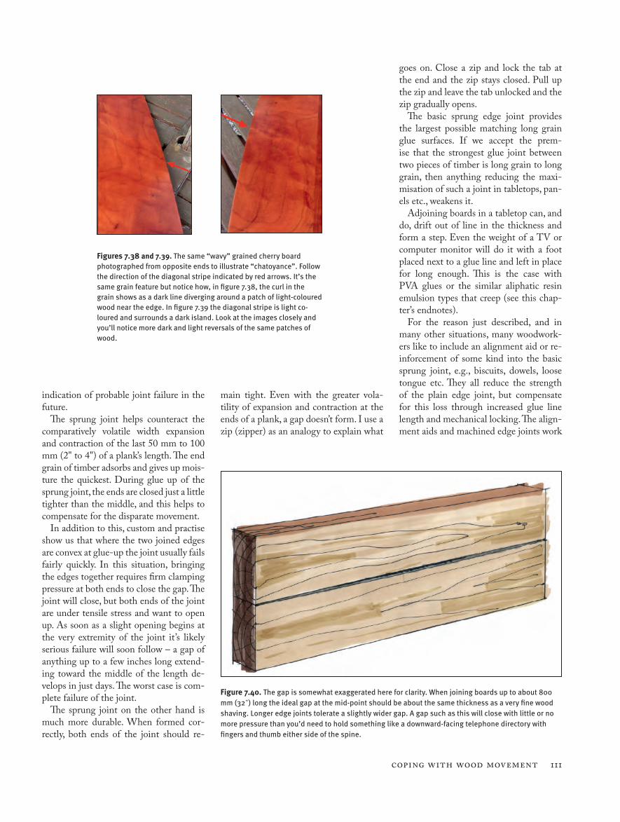
Figures 7.38 and 7.39. The same “wavy” grained cherry board photographed from opposite ends to illustrate “chatoyance”. Follow the direction of the diagonal stripe indicated by red arrows. It’s the same grain feature but notice how, in figure 7.38, the curl in the grain shows as a dark line diverging around a patch of light-coloured wood near the edge. In figure 7.39 the diagonal stripe is light co-loured and surrounds a dark island. Look at the images closely and you’ll notice more dark and light reversals of the same patches of wood.
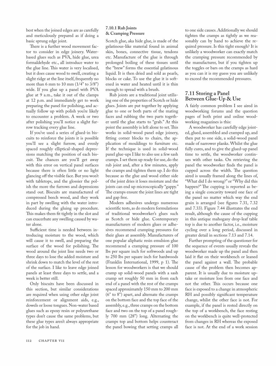
Figure 7.40. The gap is somewhat exaggerated here for clarity. When joining boards up to about 800 mm (32") long the ideal gap at the mid-point should be about the same thickness as a very fine wood shaving. Longer edge joints tolerate a slightly wider gap. A gap such as this will close with little or no more pressure than you’d need to hold something like a downward-facing telephone directory with fingers and thumb either side of the spine.
112 CHAPTER V11
best when the joined edges are as carefully and meticulously prepared as if doing a basic sprung edge joint.
There is a further wood movement fac-tor to consider in edge joinery. Water-based glues such as PVA, hide glue, urea formaldehyde etc., all introduce water to the glue line. This water is very localised, but it does cause wood to swell, creating a slight ridge at the line itself, frequently no more than 6 mm to 10 mm (1/4" to 3/8") wide. If you glue up a panel with PVA glue at 9 a.m., take it out of the clamps at 12 p.m. and immediately get to work preparing the panel for polishing, and ac-tually follow up with polish you’re likely to encounter a problem. A week or two after polishing you’ll notice a slight fur-row tracking every glue line.
If you’ve used a series of glued-in bis-cuits to reinforce the joints it is possible you’ll see a slight furrow, and evenly spaced roughly elliptical-shaped depres-sions matching the position of each bis-cuit. The chances are you’ll get away with this error on vertical panel surfaces because there is often little or no light glancing off the visible face. But you won’t with tabletops, and the glossier the pol-ish the more the furrows and depressions stand out. Biscuits are manufactured of compressed beech wood, and they work in part by swelling with the water intro-duced during the gluing up procedure. This makes them fit tightly in the slot and can exacerbate any swelling caused by wa-ter alone.
Sufficient time is needed between in-troducing moisture to the wood, which will cause it to swell, and preparing the surface of the wood for polishing. The wood around the joint line needs two or three days to lose the added moisture and shrink down to match the level of the rest of the surface. I like to leave edge joined panels at least three days to settle, and a week is better still.
Only biscuits have been discussed in this section, but similar considerations are required when using other edge joint reinforcement or alignment aids, e.g., dowels or loose tongues. Non-water based glues such as epoxy resin or polyurethane types don’t cause the same problems, but these glue types aren’t always appropriate for the job in hand.
7.10.1 Rub Joints & Cramping Pressure
Scotch glue, aka hide glue, is made of the gelatinous-like material found in animal skin, bones, connective tissue, tendons etc. Manufacture of the glue is through prolonged boiling of these tissues until the “brew” forms the essential gelatinous liquid. It is then dried and sold as pearls, blocks or cake. To use the glue it is soft-ened in water and heated until it is thin enough to spread with a brush.
Rub joints are a traditional joint utilis-ing one of the properties of Scotch or hide glues. Joints are put together by applying glue to one or both parts of the mating faces and rubbing the two parts togeth-er until the glue starts to “grab.” At this point the assembly is left alone to set. This works in solid-wood panel edge joinery, fitting corner blocks to chairs, the ap-plication of mouldings to furniture etc. If the technique is used in solid-wood panel glue-ups I like to also use a few sash cramps. I set them up ready for use, do the rub joint and, after a few minutes, apply the cramps and tighten them up. I do this because as the glue and wood either side of the joint dries it loses moisture and the joints can end up microscopically “gappy.” The cramps ensure the joint lines are tight and gap free.
Modern adhesives undergo numerous scientific tests, as do modern formulations of traditional woodworker’s glues such as Scotch or hide glue. Contemporary manufacturers of modern glues or adhe-sives recommend cramping pressures for their glues at assembly. Manufacturers of one popular aliphatic resin emulsion glue recommend a cramping pressure of 100 lbs per square inch for softwoods and up to 250 lbs per square inch for hardwoods (Franklin International, 1999, p 1). The lesson for woodworkers is that we should cramp up solid-wood panels with a sash cramp set roughly 50 mm in from each end of a panel with the rest of the cramps spaced approximately 150 mm to 200 mm (6" to 8") apart, and alternate the cramps on the bottom face and the top face of the assembly, e.g., three cramps on the bottom face and two on the top of a panel rough-ly 700 mm (28") long. Alternating the cramps top and bottom helps counteract the panel bowing that setting cramps all
to one side causes. Additionally we should tighten the cramps as tightly as we rea-sonably can by hand to achieve the re-quired pressure. Is this tight enough? It is unlikely a woodworker can exactly match the cramping pressure recommended by the manufacturer, but if you tighten up the toggles or bars on the cramps as hard as you can it is my guess you are unlikely to exceed the recommended pressures.
7.11 Storing a Panel Between Glue-Up & UseA fairly common problem I see aired in woodworking forums and the question pages of both print and online wood-working magazines is this:
A woodworker has carefully edge joint-ed, glued, assembled and cramped up, and then put to one side, a solid-wood panel made of narrower planks. Whilst the glue fully cures, and to give the glued-up panel time to settle, the woodworker contin-ues with other tasks. On retrieving the panel the woodworker finds the panel is cupped across the width. The question aired is usually framed along the lines of, “What did I do wrong?” or “Why did this happen?” The cupping is reported as be-ing a single concavity toward one face of the panel no matter which way the end grain is arranged (see figures 7.31, 7.32 and 7.33). Figure 7.44 illustrates the end result, although the cause of the cupping in this antique mahogany drop-leaf table top is due to another factor, i.e., moisture cycling over a long period, discussed in greater detail in sections 7.13 and 7.14.
Further prompting of the questioner for the sequence of events usually reveals the woodworker made up the panel and then laid it flat on their workbench or leaned the panel against a wall. The probable cause of the problem then becomes ap-parent. It is usually due to moisture up-take or moisture loss from one face and not the other. This occurs because one face is exposed to a change in atmospheric RH and possibly significant temperature change, whilst the other face is not. For example, if the panel is rested directly on the top of a workbench, the face resting on the workbench is quite well-protected from changes in RH whereas the exposed face is not. At the end of a work session
Coping with Wood Movement 113
if the heater or air-conditioning is turned off, and the workshop is not well climate controlled, this could lead to a quite rapid change in RH values and temperatures, and in both cases either upward or down-ward. The end result is the upper exposed face of the panel either adsorbs or desorbs moisture quite quickly. The sheltered face, the one resting on the workbench, does not, or does not to anywhere near the same extent.
In every case the effect is the concave side is drier than the convex side. Either the concave face has shrunk, or the damp-er face has expanded, causing the panel to cup primarily across the width. The cupping can occur overnight or it might take a few days. The worst-case scenario is a panel glued-up and left for weeks, months or even years, and the cupping has had time to become set and therefore probably intractable as far as effecting a cure. If the cupping occurred overnight it is often possible to correct it by spreading damp wood shavings on a flat surface and laying the concave face over the shavings. The moisture transfers from the shavings to the concave face of the panel and it expands, thus straightening the panel. A similar method is to lay the concave face on slightly damp grass on a warm sunny day. The sun dries out the convex face and moisture is added to the concave side. Yet another trick is to use a plant sprayer and spray some water on to the concave face to add moisture to the wood. There is no certain cure once the curve has developed, but I have found these tricks work quite often.
The real answer is to prevent this cup-ping from happening in the first place, and the best way to do this is to ensure air can get all around a glued-up panel so what affects one side affects the other side equally. This means laying the glued-up panel on stickers on a flat surface so the air can circulate and avoiding localised heat spots, e.g., ensure the panel is not sitting directly underneath a heating pan-el or hot lights – it is also a good idea to rotate the panel on the stickers from time to time. An alternative and equally effec-tive approach is to seal the panel as tightly as possible after glue-up and the glue is properly cured. A good way to do this is to shrink wrap it in a plastic film so there is
minimum contact between the panel and exterior conditions. If shrink wrapping is not possible, wrapping the panel in layers of plastic sheeting and sealing it as tightly as possible with tape works rather well.
7.12 Mitres & MovementMitres used in joinery develop gaps at the joint line as the wood expands and contracts through the seasons. The wider the pieces of wood, the longer the mitre,
and these two factors – combined with the amount of overall movement caused by expansion and contraction – mean the gaps formed are more prominent. Mitred narrow stock such as that used as protec-tive lipping on veneered tabletop edges show little or no gap at the mitre, but wide architectural door facings, aka architraves, often show significant gaps. In architec-tural work this is one good reason to cut the vertically running architraves square at the top end with the horizontal piece
Figure 7.41.
Figure 7.42. Two squares of solid European beech mitred and biscuit jointed together. The mitres radiate from the square’s centre. The wood was about 8 percent MC when this test piece was made. Beech was used because it has a high movement factor in response to moisture content changes. The left piece was put above a radiator to dry more. The right piece placed in an unheated and uninsulated garage. In the 17 days between the two photographs, Dec. 20 to Jan. 5, the shrinkage and expan-sion of each piece is evident in the gapped mitres. The piece set above a radiator, lower left, lost 2 percentage points of MC falling to 6 percent, and the piece kept in the garage, bottom right, gained 6 percentage points of MC in rising from 8 percent to 14 percent. At the end, the two square pieces had each changed width from their original 313 mm at the beginning to 310 mm, bottom left, and 320 mm, lower right.
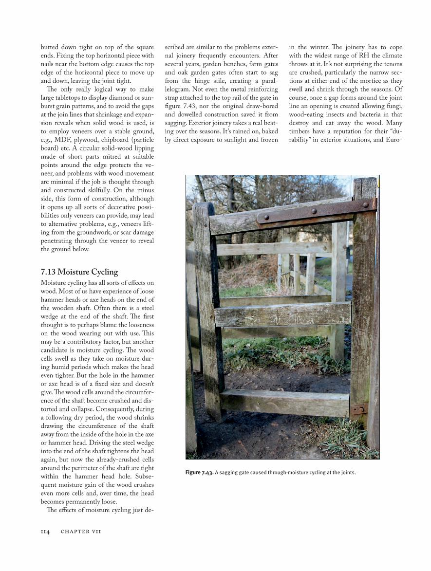
114 CHAPTER V11
butted down tight on top of the square ends. Fixing the top horizontal piece with nails near the bottom edge causes the top edge of the horizontal piece to move up and down, leaving the joint tight.
The only really logical way to make large tabletops to display diamond or sun-burst grain patterns, and to avoid the gaps at the join lines that shrinkage and expan-sion reveals when solid wood is used, is to employ veneers over a stable ground, e.g., MDF, plywood, chipboard (particle board) etc. A circular solid-wood lipping made of short parts mitred at suitable points around the edge protects the ve-neer, and problems with wood movement are minimal if the job is thought through and constructed skilfully. On the minus side, this form of construction, although it opens up all sorts of decorative possi-bilities only veneers can provide, may lead to alternative problems, e.g., veneers lift-ing from the groundwork, or scar damage penetrating through the veneer to reveal the ground below.
7.13 Moisture CyclingMoisture cycling has all sorts of effects on wood. Most of us have experience of loose hammer heads or axe heads on the end of the wooden shaft. Often there is a steel wedge at the end of the shaft. The first thought is to perhaps blame the looseness on the wood wearing out with use. This may be a contributory factor, but another candidate is moisture cycling. The wood cells swell as they take on moisture dur-ing humid periods which makes the head even tighter. But the hole in the hammer or axe head is of a fixed size and doesn’t give. The wood cells around the circumfer-ence of the shaft become crushed and dis-torted and collapse. Consequently, during a following dry period, the wood shrinks drawing the circumference of the shaft away from the inside of the hole in the axe or hammer head. Driving the steel wedge into the end of the shaft tightens the head again, but now the already-crushed cells around the perimeter of the shaft are tight within the hammer head hole. Subse-quent moisture gain of the wood crushes even more cells and, over time, the head becomes permanently loose.
The effects of moisture cycling just de-
scribed are similar to the problems exter-nal joinery frequently encounters. After several years, garden benches, farm gates and oak garden gates often start to sag from the hinge stile, creating a paral-lelogram. Not even the metal reinforcing strap attached to the top rail of the gate in figure 7.43, nor the original draw-bored and dowelled construction saved it from sagging. Exterior joinery takes a real beat-ing over the seasons. It’s rained on, baked by direct exposure to sunlight and frozen
in the winter. The joinery has to cope with the widest range of RH the climate throws at it. It’s not surprising the tenons are crushed, particularly the narrow sec-tions at either end of the mortice as they swell and shrink through the seasons. Of course, once a gap forms around the joint line an opening is created allowing fungi, wood-eating insects and bacteria in that destroy and eat away the wood. Many timbers have a reputation for their “du-rability” in exterior situations, and Euro-
Figure 7.43. A sagging gate caused through-moisture cycling at the joints.
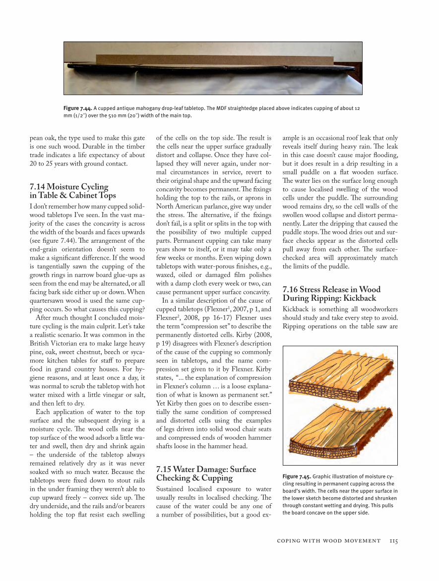
Coping with Wood Movement 115
pean oak, the type used to make this gate is one such wood. Durable in the timber trade indicates a life expectancy of about 20 to 25 years with ground contact.
7.14 Moisture Cycling in Table & Cabinet TopsI don’t remember how many cupped solid-wood tabletops I’ve seen. In the vast ma-jority of the cases the concavity is across the width of the boards and faces upwards (see figure 7.44). The arrangement of the end-grain orientation doesn’t seem to make a significant difference. If the wood is tangentially sawn the cupping of the growth rings in narrow board glue-ups as seen from the end may be alternated, or all facing bark side either up or down. When quartersawn wood is used the same cup-ping occurs. So what causes this cupping?
After much thought I concluded mois-ture cycling is the main culprit. Let’s take a realistic scenario. It was common in the British Victorian era to make large heavy pine, oak, sweet chestnut, beech or syca-more kitchen tables for staff to prepare food in grand country houses. For hy-giene reasons, and at least once a day, it was normal to scrub the tabletop with hot water mixed with a little vinegar or salt, and then left to dry.
Each application of water to the top surface and the subsequent drying is a moisture cycle. The wood cells near the top surface of the wood adsorb a little wa-ter and swell, then dry and shrink again – the underside of the tabletop always remained relatively dry as it was never soaked with so much water. Because the tabletops were fixed down to stout rails in the under framing they weren’t able to cup upward freely – convex side up. The dry underside, and the rails and/or bearers holding the top flat resist each swelling
of the cells on the top side. The result is the cells near the upper surface gradually distort and collapse. Once they have col-lapsed they will never again, under nor-mal circumstances in service, revert to their original shape and the upward facing concavity becomes permanent. The fixings holding the top to the rails, or aprons in North American parlance, give way under the stress. The alternative, if the fixings don’t fail, is a split or splits in the top with the possibility of two multiple cupped parts. Permanent cupping can take many years show to itself, or it may take only a few weeks or months. Even wiping down tabletops with water-porous finishes, e.g., waxed, oiled or damaged film polishes with a damp cloth every week or two, can cause permanent upper surface concavity.
In a similar description of the cause of cupped tabletops (Flexner1, 2007, p 1, and Flexner2, 2008, pp 16-17) Flexner uses the term “compression set” to describe the permanently distorted cells. Kirby (2008, p 19) disagrees with Flexner’s description of the cause of the cupping so commonly seen in tabletops, and the name com-pression set given to it by Flexner. Kirby states, “... the explanation of compression in Flexner’s column … is a loose explana-tion of what is known as permanent set.” Yet Kirby then goes on to describe essen-tially the same condition of compressed and distorted cells using the examples of legs driven into solid wood chair seats and compressed ends of wooden hammer shafts loose in the hammer head.
7.15 Water Damage: Surface Checking & CuppingSustained localised exposure to water usually results in localised checking. The cause of the water could be any one of a number of possibilities, but a good ex-
ample is an occasional roof leak that only reveals itself during heavy rain. The leak in this case doesn’t cause major flooding, but it does result in a drip resulting in a small puddle on a flat wooden surface. The water lies on the surface long enough to cause localised swelling of the wood cells under the puddle. The surrounding wood remains dry, so the cell walls of the swollen wood collapse and distort perma-nently. Later the dripping that caused the puddle stops. The wood dries out and sur-face checks appear as the distorted cells pull away from each other. The surface-checked area will approximately match the limits of the puddle.
7.16 Stress Release in Wood During Ripping: KickbackKickback is something all woodworkers should study and take every step to avoid. Ripping operations on the table saw are
Figure 7.44. A cupped antique mahogany drop-leaf tabletop. The MDF straightedge placed above indicates cupping of about 12 mm (1/2") over the 510 mm (20") width of the main top.
Figure 7.45. Graphic illustration of moisture cy-cling resulting in permanent cupping across the board’s width. The cells near the upper surface in the lower sketch become distorted and shrunken through constant wetting and drying. This pulls the board concave on the upper side.
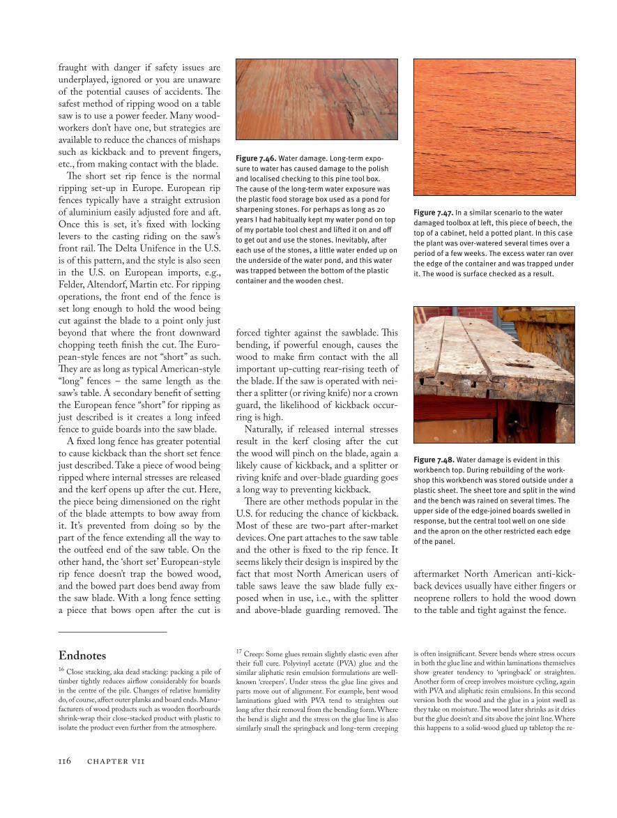
116 CHAPTER V11
fraught with danger if safety issues are underplayed, ignored or you are unaware of the potential causes of accidents. The safest method of ripping wood on a table saw is to use a power feeder. Many wood-workers don’t have one, but strategies are available to reduce the chances of mishaps such as kickback and to prevent fingers, etc., from making contact with the blade.
The short set rip fence is the normal ripping set-up in Europe. European rip fences typically have a straight extrusion of aluminium easily adjusted fore and aft. Once this is set, it’s fixed with locking levers to the casting riding on the saw’s front rail. The Delta Unifence in the U.S. is of this pattern, and the style is also seen in the U.S. on European imports, e.g., Felder, Altendorf, Martin etc. For ripping operations, the front end of the fence is set long enough to hold the wood being cut against the blade to a point only just beyond that where the front downward chopping teeth finish the cut. The Euro-pean-style fences are not “short” as such. They are as long as typical American-style “long” fences – the same length as the saw’s table. A secondary benefit of setting the European fence “short” for ripping as just described is it creates a long infeed fence to guide boards into the saw blade.
A fixed long fence has greater potential to cause kickback than the short set fence just described. Take a piece of wood being ripped where internal stresses are released and the kerf opens up after the cut. Here, the piece being dimensioned on the right of the blade attempts to bow away from it. It’s prevented from doing so by the part of the fence extending all the way to the outfeed end of the saw table. On the other hand, the ‘short set’ European-style rip fence doesn’t trap the bowed wood, and the bowed part does bend away from the saw blade. With a long fence setting a piece that bows open after the cut is
Figure 7.47. In a similar scenario to the water damaged toolbox at left, this piece of beech, the top of a cabinet, held a potted plant. In this case the plant was over-watered several times over a period of a few weeks. The excess water ran over the edge of the container and was trapped under it. The wood is surface checked as a result.
Figure 7.46. Water damage. Long-term expo-sure to water has caused damage to the polish and localised checking to this pine tool box. The cause of the long-term water exposure was the plastic food storage box used as a pond for sharpening stones. For perhaps as long as 20 years I had habitually kept my water pond on top of my portable tool chest and lifted it on and off to get out and use the stones. Inevitably, after each use of the stones, a little water ended up on the underside of the water pond, and this water was trapped between the bottom of the plastic container and the wooden chest.
Figure 7.48. Water damage is evident in this workbench top. During rebuilding of the work-shop this workbench was stored outside under a plastic sheet. The sheet tore and split in the wind and the bench was rained on several times. The upper side of the edge-joined boards swelled in response, but the central tool well on one side and the apron on the other restricted each edge of the panel.
forced tighter against the sawblade. This bending, if powerful enough, causes the wood to make firm contact with the all important up-cutting rear-rising teeth of the blade. If the saw is operated with nei-ther a splitter (or riving knife) nor a crown guard, the likelihood of kickback occur-ring is high.
Naturally, if released internal stresses result in the kerf closing after the cut the wood will pinch on the blade, again a likely cause of kickback, and a splitter or riving knife and over-blade guarding goes a long way to preventing kickback.
There are other methods popular in the U.S. for reducing the chance of kickback. Most of these are two-part after-market devices. One part attaches to the saw table and the other is fixed to the rip fence. It seems likely their design is inspired by the fact that most North American users of table saws leave the saw blade fully ex-posed when in use, i.e., with the splitter and above-blade guarding removed. The
Endnotes16 Close stacking, aka dead stacking: packing a pile of timber tightly reduces airflow considerably for boards in the centre of the pile. Changes of relative humidity do, of course, affect outer planks and board ends. Manu-facturers of wood products such as wooden floorboards shrink-wrap their close-stacked product with plastic to isolate the product even further from the atmosphere.
aftermarket North American anti-kick-back devices usually have either fingers or neoprene rollers to hold the wood down to the table and tight against the fence.
17 Creep: Some glues remain slightly elastic even after their full cure. Polyvinyl acetate (PVA) glue and the similar aliphatic resin emulsion formulations are well-known ‘creepers’. Under stress the glue line gives and parts move out of alignment. For example, bent wood laminations glued with PVA tend to straighten out long after their removal from the bending form. Where the bend is slight and the stress on the glue line is also similarly small the springback and long-term creeping
is often insignificant. Severe bends where stress occurs in both the glue line and within laminations themselves show greater tendency to ‘springback’ or straighten. Another form of creep involves moisture cycling, again with PVA and aliphatic resin emulsions. In this second version both the wood and the glue in a joint swell as they take on moisture. The wood later shrinks as it dries but the glue doesn’t and sits above the joint line. Where this happens to a solid-wood glued up tabletop the re-
Coping with Wood Movement 117
Section 7 References
Flexner1 B (2007) Finish Both Sides? Not Necessary. Popular Woodworking, Techniques [Online] Available at: <http://www.popularwoodworking.com/article/finish_both_sides_not_necessary> [Accessed July 2, 2013]
Flexner2 B (2008) ‘Finishing both sides is warped thinking’ Woodshop News, Essex CT, U.S., July
Franklin International (1999) Titebond products: Titebond Original Wood Glue, Franklin International [On-line] Available at: < http://www.titebond.com/IntroPageTB.ASP?UserType=1&ProdSel=ProductCategoryTB.asp?prodcat=1> [Accessed December 27, 2008]
Hoadley RB (2000) Understanding Wood: a craftsman’s guide to wood technology, revised edition, The Taunton Press, CT, U.S.
Joyce E (1980) The Technique of Furniture Making, 3rd Edition, BT Batsford Ltd, London
Kirby I (2008) ‘Some straight talk about warped wood’, Woodshop News, Es-sex CT, USA, September, pp 18- 19.
Kovalick B (2007) The Shrinkulator, Woodbin, Woodworking Software, [online] Available at: <http://www.woodbin.com/calcs/shrinkulator.htm> [Accessed April 15, 2007]
sult is a line of small pimples along the glue line that is just perceptible to the finger tips although, quite often, the pimples are also visible. I’ve occasionally seen the ‘row of pimples’ fault where rather wet planks, 13 per-
cent MC or so, were edge joined to make a panel which later shrank as the wood adapted to internal house con-ditions by drying to roughly 8 percent MC. Glues that never really cure hard and always remain a little elastic
allow a little movement in the joint. It is worth bearing these creep characteristics in mind when working on projects and selecting a different glue when it is judged that creep might cause a problem.