Embed Size (px)
Citation preview
Cut-and-Paste Editing of Multiresolution Surfaces
Henning Biermanny, Ioana Martinz, Fausto Bernardiniz, Denis Zoriny
yMedia Research LaboratoryNew York University
zIBM T. J. Watson Research Center
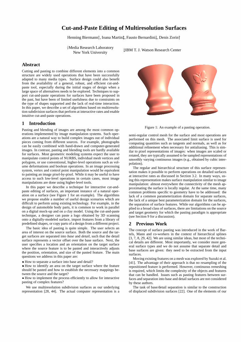
AbstractCutting and pasting to combine different elements into a commonstructure are widely used operations that have been successfullyadapted to many media types. Surface design could also benefitfrom the availability of a general, robust, and efficient cut-and-paste tool, especially during the initial stages of design when alarge space of alternatives needs to be explored. Techniques to sup-port cut-and-paste operations for surfaces have been proposed inthe past, but have been of limited usefulness due to constraints onthe type of shapes supported and the lack of real-time interaction.In this paper, we describe a set of algorithms based on multiresolu-tion subdivision surfaces that perform at interactive rates and enableintuitive cut-and-paste operations.
1 IntroductionPasting and blending of images are among the most common op-erations implemented by image manipulation systems. Such oper-ations are a natural way to build complex images out of individualpieces coming from different sources. For example, photographscan be easily combined with hand-drawn and computer-generatedimages. In contrast, pasting and blending tools are hardly availablefor surfaces. Most geometric modeling systems expect the user tomanipulate control points of NURBS, individual mesh vertices andpolygons, or use conventional, higher-level operations such as vol-ume deformations and boolean operations. In an image processingsystem, vertex and control point manipulation would be equivalentto painting an image pixel-by-pixel. While it may be useful to haveaccess to such low-level operations in certain cases, most imagemanipulations are done using higher-level tools.
In this paper we describe a technique for interactive cut-and-paste editing of surfaces, an important instance of a natural oper-ation on a surface (see Figure 1 for an example). The algorithmswe propose enable a number of useful design scenarios which aredifficult to perform using existing technology. For example, in thedesign of automobile body parts, it is common to work in parallelon a digital mock-up and on a clay model. Using the cut-and-pastetechnique, a designer can paste a logo obtained by 3D scanningonto a digitally-modeled surface, import features from a library ofpredefined shapes, or copy parts of a design from a different project.
The basic idea of pasting is quite simple. The user selects anarea of interest on the source surface. Both the source and the tar-get surfaces are separated into base and detail, such that the detailsurface represents a vector offset over the base surface. Next, theuser specifies a location and an orientation on the target surfacewhere the source feature is to be pasted and interactively adjuststhe position, orientation, and size of the pasted feature. The mainquestions we address in this paper are:
� How to separate a surface into base and detail?� How to identify an area on the target surface where the featureshould be pasted and how to establish the necessary mappings be-tween the source and the target?� How to implement the process efficiently to allow for interactivepasting of complex features?
We use multiresolution subdivision surfaces as our underlyingrepresentation [28, 44]. The actual computer representation is a
Figure 1: An example of a pasting operation.
semi-regular control mesh for the surface and most operations areperformed on this mesh. The associated limit surface is used forcomputing quantities such as tangents and normals, as well as foradditional refinement when necessary for antialiasing. This is sim-ilar to pixel representations of images: when images are scaled orrotated, they are typically assumed to be sampled representations ofsmoothly varying continuous images (e.g., obtained by cubic inter-polation).
The regular and hierarchical structure of this surface represen-tation makes it possible to perform operations on detailed surfacesat interactive rates as discussed in Section 3.2. In many ways, us-ing this representation makes surface manipulation similar to imagemanipulation: almost everywhere the connectivity of the mesh ap-proximating the surface is locally regular. At the same time, manycommon problems specific to geometry have to be addressed: thelack of a common parameterization domain for separate surfaces,the lack of a unique best parameterization domain for the surfaces,the separation of surface features. While our algorithms can be ap-plied to a broad class of surfaces, there are limitations on the sourceand target geometry for which the pasting paradigm is appropriate(see Section 9 for a discussion).
2 Previous WorkThe concept of surface pasting was introduced in the work of Bar-tels, Mann and co-workers in the context of hierarchical splines[3, 7, 8, 29, 42]. We are using similar ideas, but most of the techni-cal details are different. Most importantly, we consider more gen-eral surface types and we do not assume that separate detail andbase surfaces are given: they need to be extracted from the inputsurfaces.
Moving existing features on a mesh was explored by Suzuki et al.[41]. The advantage of their approach is that no resampling of therepositioned feature is performed. However, continuous remeshingis required, which limits the complexity of the objects and featuresthat can be handled. Issues such as pasting features between sur-faces and separation into base and detail surfaces are not consideredby these authors.
The task of base/detail separation is similar to the constructionof displaced subdivision surfaces [22]. One of the elements of our
approach, i.e., mesh smoothing to extract a base surface, was de-scribed by Kobbelt et al. [18] in the more general context of arbi-trary meshes. An alternative approach was proposed by Guskov etal.[14]. We discuss the advantages and disadvantages of restrictingthe class of surfaces to semi-regular meshes in Section 3.2. Partof our construction of base surfaces is closely related to the workof Kobbelt et al. on variational subdivision [19, 17]. It also drawsupon the work of Polthier et al. [34, 31].
Parameterization techniques are important in many geometricmodeling and texturing applications and a variety of algorithmshave been proposed, including general parameterization methods[10, 11] for reparameterization (i.e., changing connectivity to semi-regular) [9, 15, 20, 23] and texture mapping [25, 36, 30]. In [21],Kuriyama and Koneko use local parameterizations to add offsets toa surface. The work of Pedersen [32, 33] on interactively placingtextures on implicit surfaces is also relevant as it requires dynamicreparameterization of surface areas similar to pasting.
However, the problem of parameterizing a surface area over aplane with minimal visual distortion is far from solved. As ex-plained in Section 6, until recently no algorithms combining sev-eral crucial properties for our application were available. We usea variation of the remarkable algorithm by Sheffer and Sturler [39]which satisfies our requirements.
3 Pasting SurfacesWe begin with a formalized description of pasting operations onsurfaces. At this point we discuss continuous surfaces and map-pings without considering their discrete representations. Thisframework applies to a wide class of manifold surfaces, rangingfrom splines to implicit surfaces. Precise descriptions of all basicmathematical concepts that we use can be found in any standardtextbook (e.g., [43]).
3.1 Formulation of the Problem
For simplicity, we restrict our attention to parts of surfaces param-eterized over planar domains: M � R
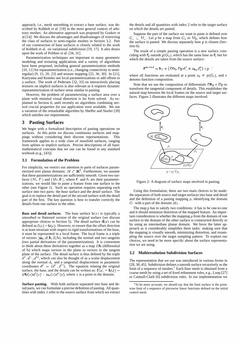
2. Furthermore, we assumethat these parameterizations are sufficiently smooth. Given two sur-faces (M1; f1) and (M2; f2), where f1 and f2 are their parameter-izations, we would like to paste a feature from one surface to theother (see Figure 1). Such an operation requires separating eachsurface into two parts: the base surface and the detail surface. Thegoal is to replace the detail part of the second surface with the detailpart of the first. The key question is how to transfer correctly thedetails from one surface to the other.
Base and detail surfaces. The base surface b(x) is typically asmoothed or flattened version of the original surface (we discussappropriate choices in Section 5). The detail surface d(x) can bedefined as f(x)�b(x). However, to ensure that the offset directionis at least invariant with respect to rigid transformations of the base,it must be represented in a local frame. The local frame is a tripleof vectors (nb; @1b; @2b), including the normal and two tangents(two partial derivatives of the parameterization). It is convenientto think about these derivatives together as a map Db (differentialof b) which maps vectors in the plane to vectors in the tangentplane of the surface. The detail surface is thus defined by the tripledn; dt1; dt2, which can also be thought of as a scalar displacementalong the normal dn and a tangential displacement in parametriccoordinates dt = (dt1; dt2). The equation relating the originalsurface, the base, and the details can be written as: f(x) = b(x) +Db(x)dt(x) + nb(x)d
n(x), where x is a point in the domain.
Surface pasting. With both surfaces separated into base and de-tail parts, we can formulate a precise definition of pasting. All quan-tities with index 1 refer to the source surface from which we extract
the details and all quantities with index 2 refer to the target surfaceon which the details are pasted.
Suppose the part of the surface we want to paste is defined overG1 � M1. Let p be a map from G1 to M2, which defines howthe surface is pasted. We discuss separately how p is chosen (Sec-tion 6).
The result of a simple pasting operation is a new surface coin-ciding with f2 outside p(G1), which has the same base as f2 but forwhich the details are taken from the source surface:
fpasted = b2 +
�Db2Dpd
t1 + nb2d
n1
�Æ p�1
where all functions are evaluated at a point x2 2 p(G1), and Ædenotes function composition.
Note that we use the composition of differentials Db2 Æ Dp totransform the tangential component of details. This establishes thenatural map between the local frames on the source and target sur-faces. Figure 2 illustrates the different maps involved.
b1
b2
M1
G1
M2
p1
p2
p1(G
1)
p2(M
2)
T
p = p2-1T p
1
Figure 2: A diagram of surface maps involved in pasting.
Using this formulation, there are two main choices to be made:the separation of both source and target surfaces into base and detailand the definition of a pasting mapping p, identifying the domainG1 with a part of the domain M2.
The map p has to satisfy two conditions: it has to be one-to-oneand it should minimize distortion of the mapped feature. An impor-tant consideration is whether the mapping p from the domain of onesurface to the domain of the other surface is constructed directly orby using an intermediate planar domain. We favor the latter ap-proach as it considerably simplifies three tasks: making sure thatthe mapping is visually smooth, minimizing distortion, and resam-pling the source over the target sampling pattern. To explain ourchoices, we need to be more specific about the surface representa-tion we are using.
3.2 Multiresolution Subdivision Surfaces
The representation that we use was introduced in various forms in[28, 38, 45]. Subdivision defines a smooth surface recursively as thelimit of a sequence of meshes.1 Each finer mesh is obtained from acoarse mesh by using a set of fixed refinement rules, e.g., Loop [27]or Catmull-Clark [6] subdivision rules. In our implementation we
1To be more accurate, we should say that the limit surface is the point-wise limit of a sequence of piecewise linear functions defined on the initialcontrol mesh.
use Catmull-Clark rules. Multiresolution surfaces extend subdivi-sion surfaces by introducing details at each level. Each time a finermesh is computed, it is obtained by adding detail offsets to the sub-divided coarse mesh. If we are given a semi-regular mesh, i.e., amesh with subdivision connectivity, we can easily convert it to amultiresolution surface if we define a smoothing operation to com-pute vertices on a coarse level from a finer level. The details arethen computed as differences between levels (see Section 5).
An aspect of multiresolution surfaces important for modificationoperations is that details are represented in local coordinate frames,which are computed from the coarser level. This is analogous torepresenting the detail surface in the frame computed from the basesurface.
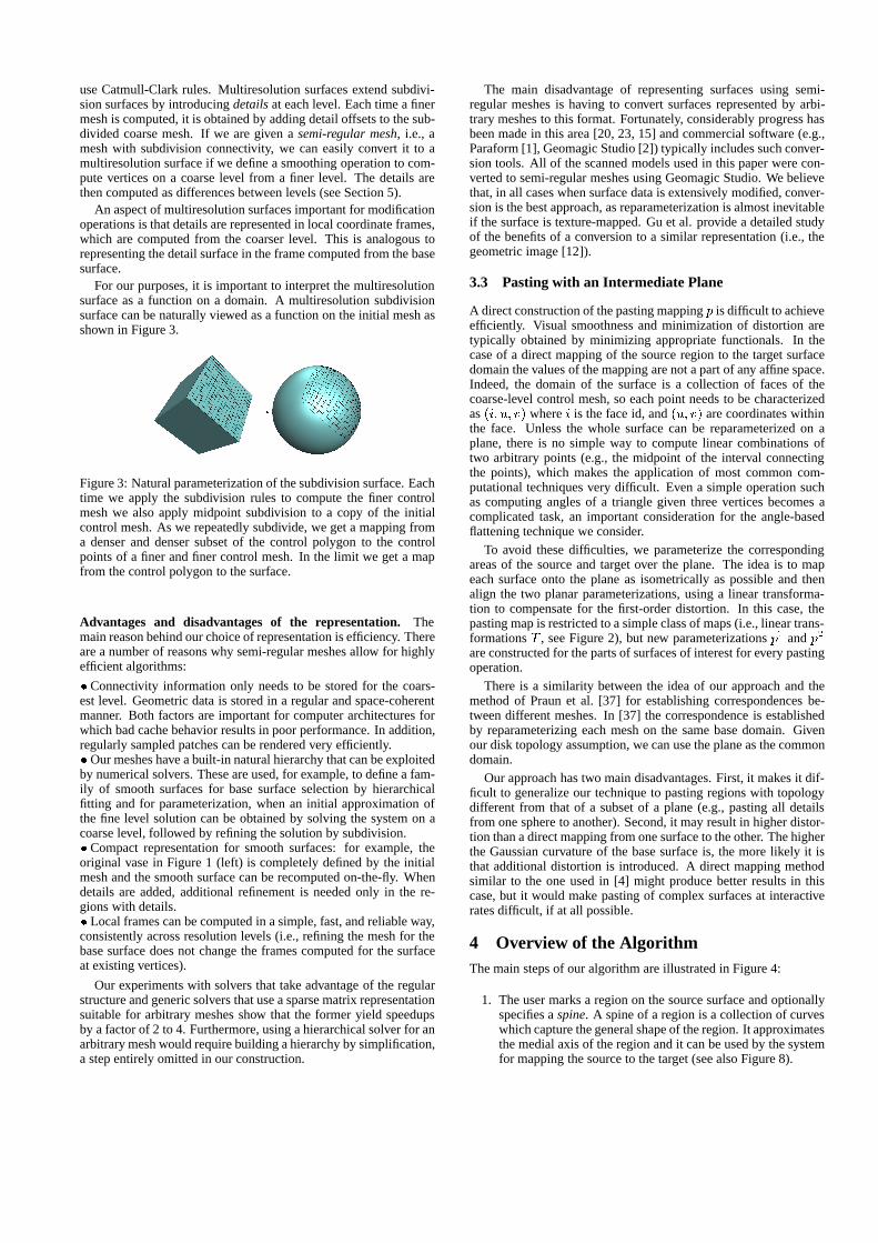
For our purposes, it is important to interpret the multiresolutionsurface as a function on a domain. A multiresolution subdivisionsurface can be naturally viewed as a function on the initial mesh asshown in Figure 3.
Figure 3: Natural parameterization of the subdivision surface. Eachtime we apply the subdivision rules to compute the finer controlmesh we also apply midpoint subdivision to a copy of the initialcontrol mesh. As we repeatedly subdivide, we get a mapping froma denser and denser subset of the control polygon to the controlpoints of a finer and finer control mesh. In the limit we get a mapfrom the control polygon to the surface.
Advantages and disadvantages of the representation. Themain reason behind our choice of representation is efficiency. Thereare a number of reasons why semi-regular meshes allow for highlyefficient algorithms:
� Connectivity information only needs to be stored for the coars-est level. Geometric data is stored in a regular and space-coherentmanner. Both factors are important for computer architectures forwhich bad cache behavior results in poor performance. In addition,regularly sampled patches can be rendered very efficiently.� Our meshes have a built-in natural hierarchy that can be exploitedby numerical solvers. These are used, for example, to define a fam-ily of smooth surfaces for base surface selection by hierarchicalfitting and for parameterization, when an initial approximation ofthe fine level solution can be obtained by solving the system on acoarse level, followed by refining the solution by subdivision.� Compact representation for smooth surfaces: for example, theoriginal vase in Figure 1 (left) is completely defined by the initialmesh and the smooth surface can be recomputed on-the-fly. Whendetails are added, additional refinement is needed only in the re-gions with details.� Local frames can be computed in a simple, fast, and reliable way,consistently across resolution levels (i.e., refining the mesh for thebase surface does not change the frames computed for the surfaceat existing vertices).
Our experiments with solvers that take advantage of the regularstructure and generic solvers that use a sparse matrix representationsuitable for arbitrary meshes show that the former yield speedupsby a factor of 2 to 4. Furthermore, using a hierarchical solver for anarbitrary mesh would require building a hierarchy by simplification,a step entirely omitted in our construction.
The main disadvantage of representing surfaces using semi-regular meshes is having to convert surfaces represented by arbi-trary meshes to this format. Fortunately, considerably progress hasbeen made in this area [20, 23, 15] and commercial software (e.g.,Paraform [1], Geomagic Studio [2]) typically includes such conver-sion tools. All of the scanned models used in this paper were con-verted to semi-regular meshes using Geomagic Studio. We believethat, in all cases when surface data is extensively modified, conver-sion is the best approach, as reparameterization is almost inevitableif the surface is texture-mapped. Gu et al. provide a detailed studyof the benefits of a conversion to a similar representation (i.e., thegeometric image [12]).
3.3 Pasting with an Intermediate Plane
A direct construction of the pasting mapping p is difficult to achieveefficiently. Visual smoothness and minimization of distortion aretypically obtained by minimizing appropriate functionals. In thecase of a direct mapping of the source region to the target surfacedomain the values of the mapping are not a part of any affine space.Indeed, the domain of the surface is a collection of faces of thecoarse-level control mesh, so each point needs to be characterizedas (i; u; v) where i is the face id, and (u; v) are coordinates withinthe face. Unless the whole surface can be reparameterized on aplane, there is no simple way to compute linear combinations oftwo arbitrary points (e.g., the midpoint of the interval connectingthe points), which makes the application of most common com-putational techniques very difficult. Even a simple operation suchas computing angles of a triangle given three vertices becomes acomplicated task, an important consideration for the angle-basedflattening technique we consider.
To avoid these difficulties, we parameterize the correspondingareas of the source and target over the plane. The idea is to mapeach surface onto the plane as isometrically as possible and thenalign the two planar parameterizations, using a linear transforma-tion to compensate for the first-order distortion. In this case, thepasting map is restricted to a simple class of maps (i.e., linear trans-formations T , see Figure 2), but new parameterizations p1 and p2
are constructed for the parts of surfaces of interest for every pastingoperation.
There is a similarity between the idea of our approach and themethod of Praun et al. [37] for establishing correspondences be-tween different meshes. In [37] the correspondence is establishedby reparameterizing each mesh on the same base domain. Givenour disk topology assumption, we can use the plane as the commondomain.
Our approach has two main disadvantages. First, it makes it dif-ficult to generalize our technique to pasting regions with topologydifferent from that of a subset of a plane (e.g., pasting all detailsfrom one sphere to another). Second, it may result in higher distor-tion than a direct mapping from one surface to the other. The higherthe Gaussian curvature of the base surface is, the more likely it isthat additional distortion is introduced. A direct mapping methodsimilar to the one used in [4] might produce better results in thiscase, but it would make pasting of complex surfaces at interactiverates difficult, if at all possible.
4 Overview of the AlgorithmThe main steps of our algorithm are illustrated in Figure 4:
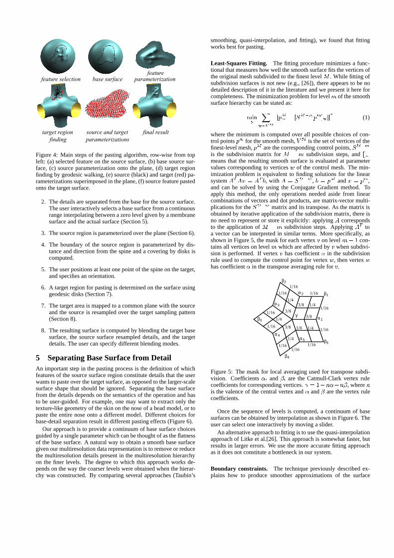
1. The user marks a region on the source surface and optionallyspecifies a spine. A spine of a region is a collection of curveswhich capture the general shape of the region. It approximatesthe medial axis of the region and it can be used by the systemfor mapping the source to the target (see also Figure 8).
feature selection base surface parameterizationfeature
target region source and target final result finding parameterizations
Figure 4: Main steps of the pasting algorithm, row-wise from topleft: (a) selected feature on the source surface, (b) base source sur-face, (c) source parameterization onto the plane, (d) target regionfinding by geodesic walking, (e) source (black) and target (red) pa-rameterizations superimposed in the plane, (f) source feature pastedonto the target surface.
2. The details are separated from the base for the source surface.The user interactively selects a base surface from a continuousrange interpolating between a zero level given by a membranesurface and the actual surface (Section 5).
3. The source region is parameterized over the plane (Section 6).
4. The boundary of the source region is parameterized by dis-tance and direction from the spine and a covering by disks iscomputed.
5. The user positions at least one point of the spine on the target,and specifies an orientation.
6. A target region for pasting is determined on the surface usinggeodesic disks (Section 7).
7. The target area is mapped to a common plane with the sourceand the source is resampled over the target sampling pattern(Section 8).
8. The resulting surface is computed by blending the target basesurface, the source surface resampled details, and the targetdetails. The user can specify different blending modes.
5 Separating Base Surface from DetailAn important step in the pasting process is the definition of whichfeatures of the source surface region constitute details that the userwants to paste over the target surface, as opposed to the larger-scalesurface shape that should be ignored. Separating the base surfacefrom the details depends on the semantics of the operation and hasto be user-guided. For example, one may want to extract only thetexture-like geometry of the skin on the nose of a head model, or topaste the entire nose onto a different model. Different choices forbase-detail separation result in different pasting effects (Figure 6).
Our approach is to provide a continuum of base surface choicesguided by a single parameter which can be thought of as the flatnessof the base surface. A natural way to obtain a smooth base surfacegiven our multiresolution data representation is to remove or reducethe multiresolution details present in the multiresolution hierarchyon the finer levels. The degree to which this approach works de-pends on the way the coarser levels were obtained when the hierar-chy was constructed. By comparing several approaches (Taubin’s
smoothing, quasi-interpolation, and fitting), we found that fittingworks best for pasting.
Least-Squares Fitting. The fitting procedure minimizes a func-tional that measures how well the smooth surface fits the vertices ofthe original mesh subdivided to the finest level M . While fitting ofsubdivision surfaces is not new (e.g., [26]), there appears to be nodetailed description of it in the literature and we present it here forcompleteness. The minimization problem for level m of the smoothsurface hierarchy can be stated as:
minp
X
w2VM
jjpMw � [SM�mpm]wjj2 (1)
where the minimum is computed over all possible choices of con-trol points pm for the smooth mesh, VM is the set of vertices of thefinest-level mesh, pM are the corresponding control points, SM�m
is the subdivision matrix for M � m subdivision steps, and []wmeans that the resulting smooth surface is evaluated at parametervalues corresponding to vertices w of the control mesh. The min-imization problem is equivalent to finding solutions for the linearsystem ATAx = AT b, with A = SM�m, b = pM and x = pm,and can be solved by using the Conjugate Gradient method. Toapply this method, the only operations needed aside from linearcombinations of vectors and dot products, are matrix-vector multi-plications for the SM�m matrix and its transpose. As the matrix isobtained by iterative application of the subdivision matrix, there isno need to represent or store it explicitly: applying A correspondsto the application of M � m subdivision steps. Applying AT toa vector can be interpreted in similar terms. More specifically, asshown in Figure 5, the mask for each vertex v on level m� 1 con-tains all vertices on level m which are affected by v when subdivi-sion is performed. If vertex v has coefficient � in the subdivisionrule used to compute the control point for vertex w, then vertex whas coefficient � in the transpose averaging rule for v.
β3 α 1
1/4
1/16
1/16
3/8
β1
β4
β5
β2
α 2
α 3
α 4α 5
1/4
1/4
1/4
1/4 1/16
1/16
1/16
1/16
1/16
1/16
1/161/16
3/8
3/8
3/8
γ
3/8
Figure 5: The mask for local averaging used for transpose subdi-vision. Coefficients �i and �i are the Catmull-Clark vertex rulecoefficients for corresponding vertices. = 1�n��n�, where nis the valence of the central vertex and � and � are the vertex rulecoefficients.
Once the sequence of levels is computed, a continuum of basesurfaces can be obtained by interpolation as shown in Figure 6. Theuser can select one interactively by moving a slider.
An alternative approach to fitting is to use the quasi-interpolationapproach of Litke et al.[26]. This approach is somewhat faster, butresults in larger errors. We use the more accurate fitting approachas it does not constitute a bottleneck in our system.
Boundary constraints. The technique previously described ex-plains how to produce smoother approximations of the surface
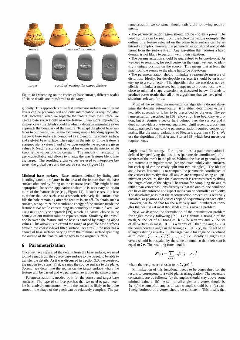
source base surface choice
target result of pasting the source feature
Figure 6: Depending on the choice of base surface, different scalesof shape details are transferred to the target.
globally. This approach is quite fast as the base surfaces on differentlevels can be precomputed and only interpolation is required afterthat. However, when we separate the feature from the surface, weneed a base surface only near the feature. Even more importantly,in most cases the details should gradually decay in magnitude as weapproach the boundary of the feature. To adapt the global base sur-faces to our needs, we use the following simple blending approach:the local base surface is computed as a blend of the source surfaceand a global base surface. The region in the interior of the feature isassigned alpha values 1 and all vertices outside the region are givenvalues 0. Next, relaxation is applied for values in the interior whilekeeping the values outside constant. The amount of relaxation isuser-controllable and allows to change the way features blend intothe target. The resulting alpha values are used to interpolate be-tween the global base and the source surface (Figure 11).
Minimal base surface. Base surfaces defined by fitting andblending cannot be flatter in the area of the feature than the basesurface obtained by fitting on the coarsest level. This might be notappropriate for some applications where it is necessary to retainmore of the feature shape (e.g., Figure 14). In such cases, it is bestto define the base surface as a smooth, relatively flat surface thatfills the hole remaining after the feature is cut off. To obtain such asurface, we optimize the membrane energy of the surface inside thefeature curve while constraining its boundary to remain fixed. Weuse a multigrid-type approach [19], which is a natural choice in thecontext of our multiresolution representation. Similarly, the transi-tion between the feature and the base is handled by assigning alphavalues. This allows us to extend the range of possible base surfacesbeyond the coarsest-level fitted surface. As a result the user has achoice of base surfaces varying from the minimal surface spanningthe outline of the feature, all the way to the original surface.
6 ParameterizationOnce we have separated the details from the base surface, we needto find a map from the source base surface to the target, to be able totransfer the details. As it was discussed in Section 3.3, we constructthe map in two steps. First, we map the source surface to the plane.Second, we determine the region on the target surface where thefeature will be pasted and we parameterize it onto the same plane.
Parameterization is needed both for the source and target basesurfaces. The type of surface patches that we need to parameter-ize is relatively uncommon: while the surface is likely to be quitesmooth, the shape of the patch can be relatively complex. The pa-
rameterization we construct should satisfy the following require-ments:
� The parameterization region should not be chosen a priori. Theneed for this can be seen from the following simple example: theoutline of a feature selected on the plane base surface can be ar-bitrarily complex, however the parameterization should not be dif-ferent from the surface itself. Any algorithm that requires a fixeddomain is not likely to perform well in this situation.� The parameterization should be guaranteed to be one-to-one. Aswe need to resample, for each vertex on the target we need to iden-tify a unique position on the source. This means that at least themap from the source to the plane has to be one-to-one.� The parameterization should minimize a reasonable measure ofdistortion. Ideally, for developable surfaces it should be an isom-etry up to a scale factor. The algorithm that we use does not ex-plicitly minimize a measure, but it appears to produce results withclose to minimal shape distortion, as discussed below. It tends toproduce better results than all other algorithms that we have tried insituations relevant for us.
Most of the existing parameterization algorithms do not deter-mine the domain automatically: it is either determined using aheuristic approach or it has to be prescribed by the user. The pa-rameterization described in [36] allows for free boundary evolu-tion, but it requires a vector field defined over the surface and itdoes not provide a one-to-one guarantee. Until recently, algorithmsthat guaranteed a one-to-one parameterization required convex do-mains, like the many variations of Floater’s algorithm ([10]). Weuse the algorithm of Sheffer and Sturler [39] which best meets ourrequirements.
Angle-based flattening. For a given mesh a parameterization isdefined by specifying the positions (parametric coordinates) of allvertices of the mesh in the plane. Without the loss of generality, wecan assume a triangular mesh (we use quad subdivision surfaces,but each quad can be easily split into two triangles). The idea ofangle-based flattening is to compute the parametric coordinates ofthe vertices indirectly: first, all angles are computed using an opti-mization procedure, then the planar mesh is reconstructed by fixingthe length of one of the edges. The reason for computing the anglesrather than vertex positions directly is that the one-to-one conditioncan be easily enforced and aspect ratios can be controlled explicitly.The disadvantage is that the reconstruction procedure is relativelyunstable, as positions of vertices depend sequentially on each other.However, we found that for the relatively small numbers of trian-gles that we use (at most thousands), this is never a problem.
Next we describe the formulation of the optimization problemfor angles mostly following [39]. Let t denote a triangle of themesh, T the set of all triangles; let v be a vertex and V the setof all vertices in mesh. If v is a vertex of t then the angle �vt isthe corresponding angle in the triangle t. Let N(v) be the set of alltriangles sharing a vertex v. The target value for angle �vt is definedas follows: 'vt = 2��vs=
Ps2N(v) �
vs , i.e., ideally all angles at a
vertex should be rescaled by the same amount, so that their sum isequal to 2�. The resulting functional is
F (�) =X
t;v2t
wvt (�
vt � 'vt )
2;
where the weights are chosen to be 1=('vt )2.
Minimization of this functional needs to be constrained for theresults to correspond to a valid planar triangulation. The necessaryconstraints are as follows: (a) the angles should stay above someminimal value �; (b) the sum of all angles at a vertex should be2�; (c) the sum of all angles of each triangle should be �; (d) each1-neighborhood of a vertex should be consistent. This means that
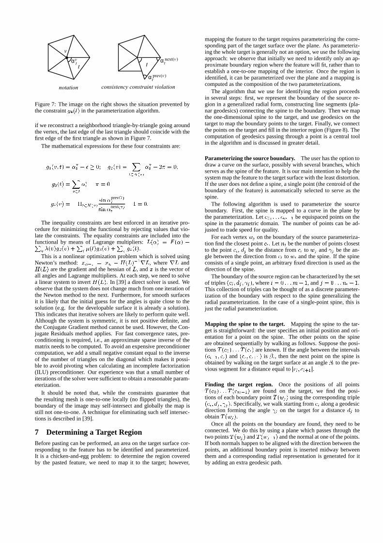
t
v
αvt αt
next(v )
αtprev(v )
t
notation consistency constraint violation
Figure 7: The image on the right shows the situation prevented bythe constraint g4(t) in the parameterization algorithm.
if we reconstruct a neighborhood triangle-by-triangle going aroundthe vertex, the last edge of the last triangle should coincide with thefirst edge of the first triangle as shown in Figure 7.
The mathematical expressions for these four constraints are:
g1(v; t) = �vt � � � 0; g2(v) =X
t2N(v)
�vt � 2� = 0;
g3(t) =X
v2t
�vt � � = 0
g4(v) = �t2N(v)sin�
prev(t)t
sin�next(v)t
� 1 = 0:
The inequality constraints are best enforced in an iterative pro-cedure for minimizing the functional by rejecting values that vio-late the constraints. The equality constraints are included into thefunctional by means of Lagrange multipliers: L(�) = F (�) +P
v �(v)g2(v) +P
t �(t)g3(v) +P
v g4(t).This is a nonlinear optimization problem which is solved using
Newton’s method: xn+1 = xn � H(L)�1rL, where rL andH(L) are the gradient and the hessian of L, and x is the vector ofall angles and Lagrange multipliers. At each step, we need to solvea linear system to invert H(L). In [39] a direct solver is used. Weobserve that the system does not change much from one iteration ofthe Newton method to the next. Furthermore, for smooth surfacesit is likely that the initial guess for the angles is quite close to thesolution (e.g. for the developable surface it is already a solution).This indicates that iterative solvers are likely to perform quite well.Although the system is symmetric, it is not positive definite, andthe Conjugate Gradient method cannot be used. However, the Con-jugate Residuals method applies. For fast convergence rates, pre-conditioning is required, i.e., an approximate sparse inverse of thematrix needs to be computed. To avoid an expensive preconditionercomputation, we add a small negative constant equal to the inverseof the number of triangles on the diagonal which makes it possi-ble to avoid pivoting when calculating an incomplete factorization(ILU) preconditioner. Our experience was that a small number ofiterations of the solver were sufficient to obtain a reasonable param-eterization.
It should be noted that, while the constraints guarantee thatthe resulting mesh is one-to-one locally (no flipped triangles), theboundary of the image may self-intersect and globally the map isstill not one-to-one. A technique for eliminating such self intersec-tions is described in [39].
7 Determining a Target RegionBefore pasting can be performed, an area on the target surface cor-responding to the feature has to be identified and parameterized.It is a chicken-and-egg problem: to determine the region coveredby the pasted feature, we need to map it to the target; however,
mapping the feature to the target requires parameterizing the corre-sponding part of the target surface over the plane. As parameteriz-ing the whole target is generally not an option, we use the followingapproach: we observe that initially we need to identify only an ap-proximate boundary region where the feature will fit, rather than toestablish a one-to-one mapping of the interior. Once the region isidentified, it can be parameterized over the plane and a mapping iscomputed as the composition of the two parameterizations.
The algorithm that we use for identifying the region proceedsin several steps: first, we represent the boundary of the source re-gion in a generalized radial form, constructing line segments (pla-nar geodesics) connecting the spine to the boundary. Then we mapthe one-dimensional spine to the target, and use geodesics on thetarget to map the boundary points to the target. Finally, we connectthe points on the target and fill in the interior region (Figure 8). Thecomputation of geodesics passing through a point is a central toolin the algorithm and is discussed in greater detail.
Parameterizing the source boundary. The user has the option todraw a curve on the surface, possibly with several branches, whichserves as the spine of the feature. It is our main intention to help thesystem map the feature to the target surface with the least distortion.If the user does not define a spine, a single point (the centroid of theboundary of the feature) is automatically selected to serve as thespine.
The following algorithm is used to parameterize the sourceboundary. First, the spine is mapped to a curve in the plane bythe parameterization. Let c0; : : : cm�1 be equispaced points on thespine in the parametric domain. The number of points can be ad-justed to trade speed for quality.
For each vertex wj on the boundary of the source parameteriza-tion find the closest point ci. Let ni be the number of points closestto the point ci, dj be the distance from ci to wj and j be the an-gle between the direction from ci to wi and the spine. If the spineconsists of a single point, an arbitrary fixed direction is used as thedirection of the spine.
The boundary of the source region can be characterized by the setof triples (ci; dj ; j), where i = 0 : : :m� 1, and j = 0 : : : ni� 1.This collection of triples can be thought of as a discrete parameter-ization of the boundary with respect to the spine generalizing theradial parameterization. In the case of a single-point spine, this isjust the radial parameterization.
Mapping the spine to the target. Mapping the spine to the tar-get is straightforward: the user specifies an initial position and ori-entation for a point on the spine. The other points on the spineare obtained sequentially by walking as follows. Suppose the posi-tions T (c0) : : : T (ci) are known. If the angle between the intervals(ci�1; ci) and (ci; ci+1) is �i, then the next point on the spine isobtained by walking on the target surface at an angle �i to the pre-vious segment for a distance equal to jci; ci+1j.
Finding the target region. Once the positions of all pointsT (c0) : : : T (cm�1) are found on the target, we find the posi-tions of each boundary point T (wj) using the corresponding triple(ci; dj ; j). Specifically, we walk starting from ci along a geodesicdirection forming the angle j on the target for a distance dj toobtain T (wj).
Once all the points on the boundary are found, they need to beconnected. We do this by using a plane which passes through thetwo points T (wj) and T (wj+1) and the normal at one of the points.If both normals happen to be aligned with the direction between thepoints, an additional boundary point is inserted midway betweenthem and a corresponding radial representation is generated for itby adding an extra geodesic path.
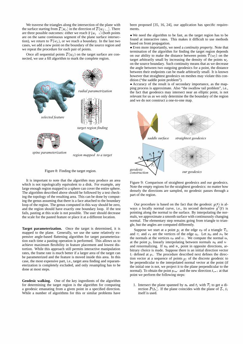
We traverse the triangles along the intersection of the plane withthe surface starting from T (wj) in the direction of T (wj+1). Thereare three possible outcomes: either we reach T (wj+1) (both pointsare on the same continuous segment of the plane surface intersec-tion), we return to T (wj), or we reach a boundary. In the last twocases, we add a new point on the boundary of the source region andwe repeat the procedure for each pair of points.
Once all sequential points T (wj) on the target surface are con-nected, we use a fill algorithm to mark the complete region.
radial parametrization
selected feature
target region finding
spine parameterizationregion mapped to a target
Figure 8: Finding the target region.
It is important to note that the algorithm may produce an areawhich is not topologically equivalent to a disk. For example, anylarge enough region mapped to a sphere can cover the entire sphere.The algorithm described above should be followed by a test check-ing the topology of the resulting area. This can be done by comput-ing the genus assuming that there is a face attached to the boundaryloop of the region. The genus computed in this way should be zero,and the region should have exactly one boundary loop. If the testfails, pasting at this scale is not possible. The user should decreasethe scale for the pasted feature or place it at a different location.
Target parameterization. Once the target is determined, it ismapped to the plane. Generally, we use the same relatively ex-pensive angle-based flattening algorithm for target parameteriza-tion each time a pasting operation is performed. This allows us toachieve maximum flexibility in feature placement and lowest dis-tortion. While this approach still permits interactive manipulationrates, the frame rate is much better if a larger area of the target canbe parameterized and the feature is moved inside this area. In thiscase, the most expensive part, i.e., target area finding and reparam-eterization is completely excluded, and only resampling has to bedone at most steps.
Geodesic walking. One of the key ingredients of the algorithmfor determining the target region is the algorithm for computinga geodesic emanating from a given point in a specified direction.While a number of algorithms for this or similar problems have
been proposed [35, 16, 24], our application has specific require-ments.
� We need the algorithm to be fast, as the target region has to befound at interactive rates. This makes it difficult to use methodsbased on front propagation.� Even more importantly, we need a continuity property. Note thattermination of the algorithm for finding the target region dependson our ability to make the distance between points T (wj) on thetarget arbitrarily small by increasing the density of the points wjon the source boundary. Such continuity means that as we decreasethe angle between two outgoing geodesics for a point, the distancebetween their endpoints can be made arbitrarily small. It is knownhowever that straightest geodesics on meshes may violate this con-dition (“the saddle point problem”).� Accuracy of the result is of secondary importance, as the map-ping process is approximate. Also “the swallow tail problem”, i.e.,the fact that geodesics may intersect near an elliptic point, is notrelevant for us as we only determine the the boundary of the regionand we do not construct a one-to-one map.
saddle surface straightest geodesics
pi
nin
1
n0
geodesicconstruction our geodesics
Figure 9: Comparison of straightest geodesics and our geodesics.Note the empty regions for the straightest geodesics: no matter howdensely the directions are sampled, no geodesic passes through apart of the region.
Our procedure is based on the fact that the geodesic g(t) is al-ways a locally normal curve, i.e., its second derivative g00(t) ispointing along the normal to the surface. By interpolating the nor-mals, we approximate a smooth surface with continuously changingnormal. The elementary step remains going from triangle to trian-gle, but the angles are computed differently.
Suppose we start at a point pi at the edge e0 of a triangle Ti,and v0 and v1 are the vertices of the edge e0. Let n0 and n1 bethe normals at the vertices v0 and v1. We compute the normal niat the point pi linearly interpolating between normals n0 and n1and renormalizing. If n0 and n1 point in opposite directions, ar-bitrary choice is made. Suppose there is an initial direction vectorti defined at pi. The procedure described next defines the direc-tion vector at a sequence of points pj of the discrete geodesic tobe perpendicular to the interpolated normal vector at the point (ifthe initial one is not, we project it to the plane perpendicular to thenormal). To obtain the point pi+1 and the new direction ti+1 at thatpoint we perform the following steps:
1. Intersect the plane spanned by ni and ti with Ti to get a di-rection P (ti). If the plane coincides with the plane of Ti, tiitself is used.
2. Intersect the line along P (ti) in the triangle Ti with its edgesto get the point pi+1. Suppose the intersected edge is e1 withendpoints v1 and v2. The next triangle Ti+1 is the triangleacross the edge e1.
3. Compute the normal ni+1 at pi+1 by linearly interpolatingbewtween n1 and n2 at vertices v1 and v2. Project the di-rection P (ti) onto the plane perpendicular to ni+1 to obtainti+1. If P (ti) is parallel to ni+1, we use the average of theprojections obtained for two small perturbations of position ofthe point pi+1.
It can be verified that this procedure satisfies the continuity re-quirement if the mesh approximating the surface is smooth enough,i.e., the projection of the ring of triangles around any vertex ontothe plane perpendicular to the normal is one-to-one.
8 Mapping and ResamplingOnce the mappings from the source and target to the plane are es-tablished, their planar images are aligned using the point and ori-entation correspondences specified by the user when the target areawas chosen. The final step in the pasting algorithm is resamplingand combining the details from the source with the details and basesurface of the target.
For every vertex v of the parameterization of the target whichis inside the parameterization domain of the source, we find thecorresponding quad of the source parameterization. Next, u; v co-ordinates are computed in this quad and the source is evaluated.Evaluation can be done in two ways: for fast resampling, the valuesof the source at the vertices of the quad are interpolated. For higherquality, subdivision surface evaluation [40] should be used. This issimilar to using bilinear filters for fast image editing and bi-cubicfiltering for a higher-quality final result.
Adaptive refinement and sampling. The further away the ge-ometry of the feature is from a displacement map, the less suitablepasting for surface operations is. However, in some cases it is de-sirable to use the pasting paradigm to place objects which cannotbe reparameterized over the plane without considerable distortion(Figure 14 left). In other cases, the resolution of the source surfaceis substantially higher than the resolution of the target. In thesecases, uniform sampling of the target is not adequate and a formof adaptivity is needed. Hybrid meshes [13] offer the maximal de-gree of flexibility, as it is possible to perform irregular refinement insome spots and align mesh edges exactly with pasted feature edges.We use a more conventional approach where only regular refine-ment of individual faces is allowed. However, rather than quadri-secting individual faces recursively according to a criterion, we es-timate the local density of the source samples over a target face. Weuse this estimate to directly compute the subdivision level requiredfor a given face and we refine faces to that level uniformly.
9 ResultsA number of models created using our system are shown in Fig-ures 12 to 14. Figure 12 shows how details from a scanned objectare pasted on a simple vase model. In this case, the target objectitself serves as the base surface. Similarly, Figure 13 demonstrateshow details from a scanned model can be combined with a differ-ent computer-generated model. Figure 14 (right) demonstrates howa medium scale detail can be pasted on a surface while preserv-ing small-scale surface details. Figure 14 (left) shows examples offeature manipulation on the surface.
In all cases the operations were performed interactively, but theframe rate varied greatly depending on the complexity of the fea-ture, the complexity of the target region, and the sampling density
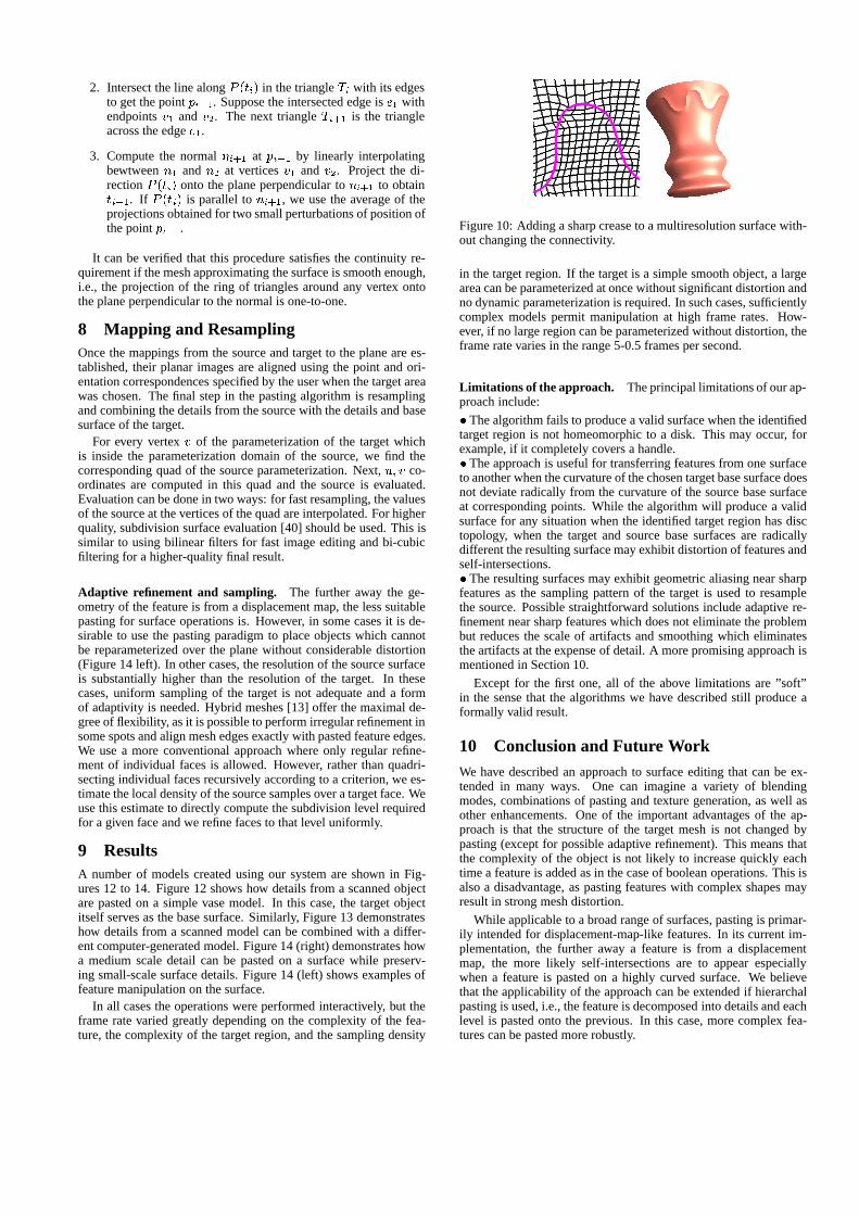
Figure 10: Adding a sharp crease to a multiresolution surface with-out changing the connectivity.
in the target region. If the target is a simple smooth object, a largearea can be parameterized at once without significant distortion andno dynamic parameterization is required. In such cases, sufficientlycomplex models permit manipulation at high frame rates. How-ever, if no large region can be parameterized without distortion, theframe rate varies in the range 5-0.5 frames per second.
Limitations of the approach. The principal limitations of our ap-proach include:
� The algorithm fails to produce a valid surface when the identifiedtarget region is not homeomorphic to a disk. This may occur, forexample, if it completely covers a handle.� The approach is useful for transferring features from one surfaceto another when the curvature of the chosen target base surface doesnot deviate radically from the curvature of the source base surfaceat corresponding points. While the algorithm will produce a validsurface for any situation when the identified target region has disctopology, when the target and source base surfaces are radicallydifferent the resulting surface may exhibit distortion of features andself-intersections.� The resulting surfaces may exhibit geometric aliasing near sharpfeatures as the sampling pattern of the target is used to resamplethe source. Possible straightforward solutions include adaptive re-finement near sharp features which does not eliminate the problembut reduces the scale of artifacts and smoothing which eliminatesthe artifacts at the expense of detail. A more promising approach ismentioned in Section 10.
Except for the first one, all of the above limitations are ”soft”in the sense that the algorithms we have described still produce aformally valid result.
10 Conclusion and Future WorkWe have described an approach to surface editing that can be ex-tended in many ways. One can imagine a variety of blendingmodes, combinations of pasting and texture generation, as well asother enhancements. One of the important advantages of the ap-proach is that the structure of the target mesh is not changed bypasting (except for possible adaptive refinement). This means thatthe complexity of the object is not likely to increase quickly eachtime a feature is added as in the case of boolean operations. This isalso a disadvantage, as pasting features with complex shapes mayresult in strong mesh distortion.
While applicable to a broad range of surfaces, pasting is primar-ily intended for displacement-map-like features. In its current im-plementation, the further away a feature is from a displacementmap, the more likely self-intersections are to appear especiallywhen a feature is pasted on a highly curved surface. We believethat the applicability of the approach can be extended if hierarchalpasting is used, i.e., the feature is decomposed into details and eachlevel is pasted onto the previous. In this case, more complex fea-tures can be pasted more robustly.
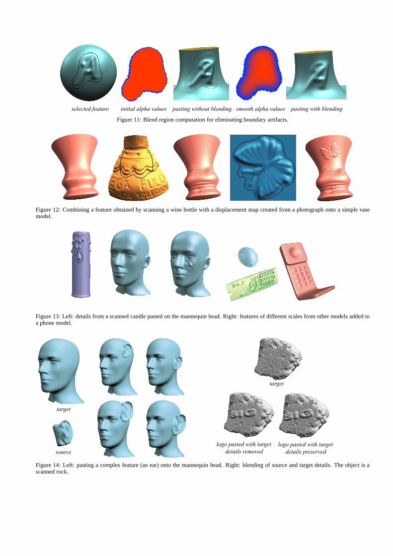
selected feature initial alpha values pasting without blending smooth alpha values pasting with blending
Figure 11: Blend region computation for eliminating boundary artifacts.
Figure 12: Combining a feature obtained by scanning a wine bottle with a displacement map created from a photograph onto a simple vasemodel.
Figure 13: Left: details from a scanned candle pasted on the mannequin head. Right: features of different scales from other models added toa phone model.
target
logo pasted with target details removed
logo pasted with target details preserved
target
source
Figure 14: Left: pasting a complex feature (an ear) onto the mannequin head. Right: blending of source and target details. The object is ascanned rock.
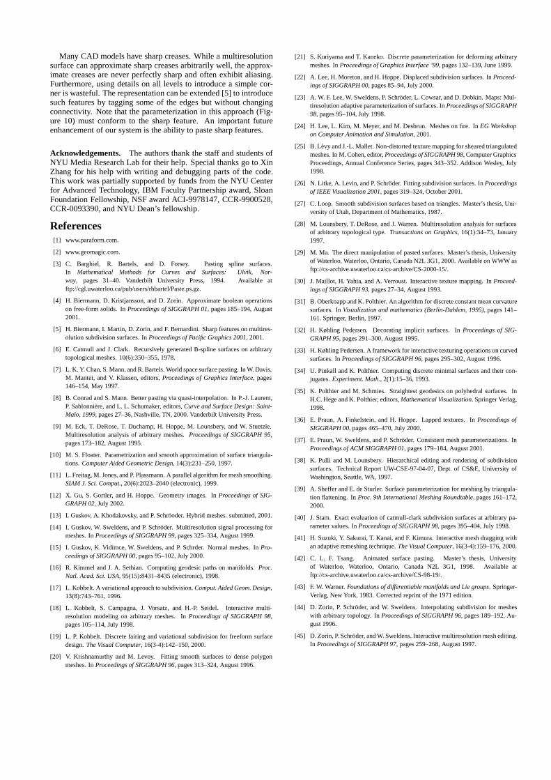
Many CAD models have sharp creases. While a multiresolutionsurface can approximate sharp creases arbitrarily well, the approx-imate creases are never perfectly sharp and often exhibit aliasing.Furthermore, using details on all levels to introduce a simple cor-ner is wasteful. The representation can be extended [5] to introducesuch features by tagging some of the edges but without changingconnectivity. Note that the parameterization in this approach (Fig-ure 10) must conform to the sharp feature. An important futureenhancement of our system is the ability to paste sharp features.
Acknowledgements. The authors thank the staff and students ofNYU Media Research Lab for their help. Special thanks go to XinZhang for his help with writing and debugging parts of the code.This work was partially supported by funds from the NYU Centerfor Advanced Technology, IBM Faculty Partnership award, SloanFoundation Fellowship, NSF award ACI-9978147, CCR-9900528,CCR-0093390, and NYU Dean’s fellowship.
References[1] www.paraform.com.
[2] www.geomagic.com.
[3] C. Barghiel, R. Bartels, and D. Forsey. Pasting spline surfaces.In Mathematical Methods for Curves and Surfaces: Ulvik, Nor-way, pages 31–40. Vanderbilt University Press, 1994. Available atftp://cgl.uwaterloo.ca/pub/users/rhbartel/Paste.ps.gz.
[4] H. Biermann, D. Kristjansson, and D. Zorin. Approximate boolean operationson free-form solids. In Proceedings of SIGGRAPH 01, pages 185–194, August2001.
[5] H. Biermann, I. Martin, D. Zorin, and F. Bernardini. Sharp features on multires-olution subdivision surfaces. In Proceedings of Pacific Graphics 2001, 2001.
[6] E. Catmull and J. Clark. Recursively generated B-spline surfaces on arbitrarytopological meshes. 10(6):350–355, 1978.
[7] L. K. Y. Chan, S. Mann, and R. Bartels. World space surface pasting. In W. Davis,M. Mantei, and V. Klassen, editors, Proceedings of Graphics Interface, pages146–154, May 1997.
[8] B. Conrad and S. Mann. Better pasting via quasi-interpolation. In P.-J. Laurent,P. Sablonniere, and L. L. Schumaker, editors, Curve and Surface Design: Saint-Malo, 1999, pages 27–36, Nashville, TN, 2000. Vanderbilt University Press.
[9] M. Eck, T. DeRose, T. Duchamp, H. Hoppe, M. Lounsbery, and W. Stuetzle.Multiresolution analysis of arbitrary meshes. Proceedings of SIGGRAPH 95,pages 173–182, August 1995.
[10] M. S. Floater. Parametrization and smooth approximation of surface triangula-tions. Computer Aided Geometric Design, 14(3):231–250, 1997.
[11] L. Freitag, M. Jones, and P. Plassmann. A parallel algorithm for mesh smoothing.SIAM J. Sci. Comput., 20(6):2023–2040 (electronic), 1999.
[12] X. Gu, S. Gortler, and H. Hoppe. Geometry images. In Proceedings of SIG-GRAPH 02, July 2002.
[13] I. Guskov, A. Khodakovsky, and P. Schrooder. Hybrid meshes. submitted, 2001.
[14] I. Guskov, W. Sweldens, and P. Schroder. Multiresolution signal processing formeshes. In Proceedings of SIGGRAPH 99, pages 325–334, August 1999.
[15] I. Guskov, K. Vidimce, W. Sweldens, and P. Schrder. Normal meshes. In Pro-ceedings of SIGGRAPH 00, pages 95–102, July 2000.
[16] R. Kimmel and J. A. Sethian. Computing geodesic paths on manifolds. Proc.Natl. Acad. Sci. USA, 95(15):8431–8435 (electronic), 1998.
[17] L. Kobbelt. A variational approach to subdivision. Comput. Aided Geom. Design,13(8):743–761, 1996.
[18] L. Kobbelt, S. Campagna, J. Vorsatz, and H.-P. Seidel. Interactive multi-resolution modeling on arbitrary meshes. In Proceedings of SIGGRAPH 98,pages 105–114, July 1998.
[19] L. P. Kobbelt. Discrete fairing and variational subdivision for freeform surfacedesign. The Visual Computer, 16(3-4):142–150, 2000.
[20] V. Krishnamurthy and M. Levoy. Fitting smooth surfaces to dense polygonmeshes. In Proceedings of SIGGRAPH 96, pages 313–324, August 1996.
[21] S. Kuriyama and T. Kaneko. Discrete parameterization for deforming arbitrarymeshes. In Proceedings of Graphics Interface ’99, pages 132–139, June 1999.
[22] A. Lee, H. Moreton, and H. Hoppe. Displaced subdivision surfaces. In Proceed-ings of SIGGRAPH 00, pages 85–94, July 2000.
[23] A. W. F. Lee, W. Sweldens, P. Schroder, L. Cowsar, and D. Dobkin. Maps: Mul-tiresolution adaptive parameterization of surfaces. In Proceedings of SIGGRAPH98, pages 95–104, July 1998.
[24] H. Lee, L. Kim, M. Meyer, and M. Desbrun. Meshes on fire. In EG Workshopon Computer Animation and Simulation, 2001.
[25] B. Levy and J.-L. Mallet. Non-distorted texture mapping for sheared triangulatedmeshes. In M. Cohen, editor, Proceedings of SIGGRAPH 98, Computer GraphicsProceedings, Annual Conference Series, pages 343–352. Addison Wesley, July1998.
[26] N. Litke, A. Levin, and P. Schroder. Fitting subdivision surfaces. In Proceedingsof IEEE Visualization 2001, pages 319–324, October 2001.
[27] C. Loop. Smooth subdivision surfaces based on triangles. Master’s thesis, Uni-versity of Utah, Department of Mathematics, 1987.
[28] M. Lounsbery, T. DeRose, and J. Warren. Multiresolution analysis for surfacesof arbitrary topological type. Transactions on Graphics, 16(1):34–73, January1997.
[29] M. Ma. The direct manipulation of pasted surfaces. Master’s thesis, Universityof Waterloo, Waterloo, Ontario, Canada N2L 3G1, 2000. Available on WWW asftp://cs-archive.uwaterloo.ca/cs-archive/CS-2000-15/.
[30] J. Maillot, H. Yahia, and A. Verroust. Interactive texture mapping. In Proceed-ings of SIGGRAPH 93, pages 27–34, August 1993.
[31] B. Oberknapp and K. Polthier. An algorithm for discrete constant mean curvaturesurfaces. In Visualization and mathematics (Berlin-Dahlem, 1995), pages 141–161. Springer, Berlin, 1997.
[32] H. Køhling Pedersen. Decorating implicit surfaces. In Proceedings of SIG-GRAPH 95, pages 291–300, August 1995.
[33] H. Køhling Pedersen. A framework for interactive texturing operations on curvedsurfaces. In Proceedings of SIGGRAPH 96, pages 295–302, August 1996.
[34] U. Pinkall and K. Polthier. Computing discrete minimal surfaces and their con-jugates. Experiment. Math., 2(1):15–36, 1993.
[35] K. Polthier and M. Schmies. Straightest geodesics on polyhedral surfaces. InH.C. Hege and K. Polthier, editors, Mathematical Visualization. Springer Verlag,1998.
[36] E. Praun, A. Finkelstein, and H. Hoppe. Lapped textures. In Proceedings ofSIGGRAPH 00, pages 465–470, July 2000.
[37] E. Praun, W. Sweldens, and P. Schroder. Consistent mesh parameterizations. InProceedings of ACM SIGGRAPH 01, pages 179–184, August 2001.
[38] K. Pulli and M. Lounsbery. Hierarchical editing and rendering of subdivisionsurfaces. Technical Report UW-CSE-97-04-07, Dept. of CS&E, University ofWashington, Seattle, WA, 1997.
[39] A. Sheffer and E. de Sturler. Surface parameterization for meshing by triangula-tion flattening. In Proc. 9th International Meshing Roundtable, pages 161–172,2000.
[40] J. Stam. Exact evaluation of catmull-clark subdivision surfaces at arbitrary pa-rameter values. In Proceedings of SIGGRAPH 98, pages 395–404, July 1998.
[41] H. Suzuki, Y. Sakurai, T. Kanai, and F. Kimura. Interactive mesh dragging withan adaptive remeshing technique. The Visual Computer, 16(3-4):159–176, 2000.
[42] C. L. F. Tsang. Animated surface pasting. Master’s thesis, Universityof Waterloo, Waterloo, Ontario, Canada N2L 3G1, 1998. Available atftp://cs-archive.uwaterloo.ca/cs-archive/CS-98-19/.
[43] F. W. Warner. Foundations of differentiable manifolds and Lie groups. Springer-Verlag, New York, 1983. Corrected reprint of the 1971 edition.
[44] D. Zorin, P. Schroder, and W. Sweldens. Interpolating subdivision for mesheswith arbitrary topology. In Proceedings of SIGGRAPH 96, pages 189–192, Au-gust 1996.
[45] D. Zorin, P. Schroder, and W. Sweldens. Interactive multiresolution mesh editing.In Proceedings of SIGGRAPH 97, pages 259–268, August 1997.