Embed Size (px)
Citation preview

Customer Event Madei Taas | September 2016 © 2016 General Electric Company – All rights reserved

Imagination at work © 2016 General Electric Company – All rights reserved
Electricity & heat from Biogas and Landfill gas applications• Challenges and proven solutions• Trends from Europe and other regions

Customer Event Madei Taas | September 2016 © 2016 General Electric Company – All rights reserved
Landfill Waste Water Treatment Plant
Kitchen waste (Food, Oil, cooking fat ..)Agricultural Waste
Biomass sources
Customer Event Madei Taas | September 2016 © 2016 General Electric Company – All rights reserved
Landfill gas• More than 1,800 of GE’s
landfill gas engines* with an electrical output of about 1,900 MW worldwide
• Organic decomposition produces fuel gas
• Waste from U.S. city of one million can power 8 MW plant
*as of June 2011

Customer Event Madei Taas | September 2016 © 2016 General Electric Company – All rights reserved
Utilization of Landfill GasNent/Hongkong2 x J320 Electrical Output 2 x 922 kW

Customer Event Madei Taas | September 2016 © 2016 General Electric Company – All rights reserved
Largest Landfill Gas Power Plant in France
The 17.3-megawatt (MW) facility is the country’s most powerful landfill gas-fueled power plant and features 10 of GE’s Jenbacher gas engines to generate renewable electricity and heat for residents and businesses. The cogeneration facility also produces 30,000 MWh/year of thermal energy, equivalent to the amount consumed by an estimated 2,850 homes.
© 2016 General Electric Company – All rights reserved 6

Customer Event Madei Taas | September 2016 © 2016 General Electric Company – All rights reserved
> 4,300 Jenbacher biogas engines >3,000 MW worldwide
• Anaerobic digestion produces fuel gas
• Renewable – from organic and animal waste
• 7,000 cows can power 1 MW plant
Biogas

Customer Event Madei Taas | September 2016 © 2016 General Electric Company – All rights reserved
Biogas Plant – typical solution
GE scope ~35% of total biogas plant capex :Jenbacher engine, heat exchangers, generator
Source: GE Jenbacher/KWE

Customer Event Madei Taas | September 2016 © 2016 General Electric Company – All rights reserved
Model solution for ecological and economical energy generation
The biogas plant in Soltau, Germany, uses corn and rye as biomass to power three of GE's Jenbacher J420 cogeneration systems. The facility generates 4.2 MW of electricity, which is fed into the regional grid. In addition, the Jenbacher engines produce 4.3 MW of thermal energy, which is used to support an integrated yeast-production process.

Customer Event Madei Taas | September 2016 © 2016 General Electric Company – All rights reserved
Animal waste
1 LSU = 0.6 - 1.2 milking cowapprox. 1.3 m³ Biogas/LSU, dayLHV = approx. 6.0 kWh/Nm³~7,000 cows = 1 MWel
1 LSU = 2 - 6 hogsapprox. 1.5 m³ Biogas/LSU, dayLHV = approx. 6.0 kWh/Nm³~70,000 hogs = 1 MWel
1 LSU = 250 - 320 layersapprox. 2 m³ Biogas/LSU, dayLHV = approx. 6.5 kWh/Nm³~1.4 million layers = 1 MWel
1 Live Stock Unit (LSU) = 500 kg live weight respectively
Energy potencial Advantages of anaerobic digestion
For the Farmer• Improvement of manure
properties: odor reduction, elimination of acid components, viscosity decrease, mineralization of organic nitrogen, reduction of pathogenic germs and weed seeds
• Additional income from heat and power production
For the Environment• Reduction of methane and
ammonia emissions from manure• Reduction of nitrate wash-out into
groundwater• Recycling of fertilizer compounds
from organic wastes• Reduction of carbon dioxide
emissions by substitution of fossil resources

Customer Event Madei Taas | September 2016 © 2016 General Electric Company – All rights reserved
Palm oil … promising electricity supplier for the future
The palm oil production process generates huge quantities of organic waste material that, if not processed, has a negative impact on the ecological balance. In Thailand, two type 3 of GE’s Jenbacher gas engines are supplying 33,000 Thai households with a reliable electrical output of 2.1 MW.
GE Distributed Power Business 2015

Customer Event Madei Taas | September 2016 © 2016 General Electric Company – All rights reserved
Palm Oil Biogas (POME) Technologies Covered Lagoon
type Hybrid in-ground type Tank Type CSTR
12

Reliable
13
Type 4 – Distributed Power| 2014© General Electric Company 2014 – All rights reserved.

Customer Event Madei Taas | September 2016 © 2016 General Electric Company – All rights reserved
Availability• The outstanding Reliability of Type 3 results in very low unscheduled downtime.
• The Easy to maintain concept enables very low scheduled downtime.
• This results in outstanding Availability and short customer return of investment.
14
Average of remotely connected engines have shown an availability of >98%
Examples• Bio-Energie Gosdorf, Austria, 1 x J312 biogas -
99.8%
• NV Groeikracht Lierbaan, Belgium, 1 x J312 CHP NG – 99.9%
• Perin SRL, Italy, 1 x J320 biogas – 99.8%
Outstanding reliability enables high availability
© General Electric Company 2014 – All rights reserved.Type 3 – Distributed Power| 2014

Customer Event Madei Taas | September 2016 © 2016 General Electric Company – All rights reserved
Proven very high availability…
* Source: Internal statistics, Jenbacher remotely connected engines in 2011
Extract: Annual availability of Top 5 Type 3 biogas plants in Switzerland
2013Plant # Site Engine
Oph @
31.12.2013
Oph/year
[hrs]
Downtime
[hrs]
Availability
[%]
1 ### J320 58.500 8.702 58 99,34%
2 ### J312 21.643 8.671 89 98,98%
3 ### J320 19.719 8.639 121 98,62%
4 ### J312 45.490 8.620 140 98,40%
5 ### J312 40.109 8.620 140 98,40%
2012Plant # Site engine
Oph @
31.12.2012
Oph/year
[hrs]
Downtime
[hrs]
Availability
[%]
1 ### J320 55.546 8.749 11 99,87%
2 ### J312 30.902 8.723 37 99,58%
3 ### J320 40.469 8.703 57 99,35%
4 ### J312 26.558 8.689 71 99,19%
5 ### J320 11.080 8.687 73 99,17%

Type 3 offers attractive savings10,000$ savings with 1%pt extra availability
A J312 biogas unit delivers extra revenue per %ptavailability of
10,000$ … 1 year
50,000$ … 5 years
100,000$ … 10 years
500 kWe in Germany EEG @ 21US$ct/kWhel with 8,500oph/y
Average >98% fleet availability1% pt availability = ~ 1%pt efficiency
0
20
40
60
80
100
1 2 3 4 5 6 7 8 9 10
Ext
ra r
even
ues
in k
$
Years of operation
16© General Electric Company 2014 – All rights reserved.Type 3 – Distributed Power| 2014

Section header layout uses 54 pt lorem ipsum

Customer Event Madei Taas | September 2016 © 2016 General Electric Company – All rights reserved
Critical interfaces for a reliable plant operation

Customer Event Madei Taas | September 2016 © 2016 General Electric Company – All rights reserved
Fuel Gas Quality and Influence on Engine Operation
Engine installationTI 1000 - 0041
Engine room ventilationTI 1100 - 0110
Exhaust gas systemTI 1100 - 0110/ TI 1100 - 0112
Hydraulic integrationTI 1100 – 0110 TI 1000 – 0206
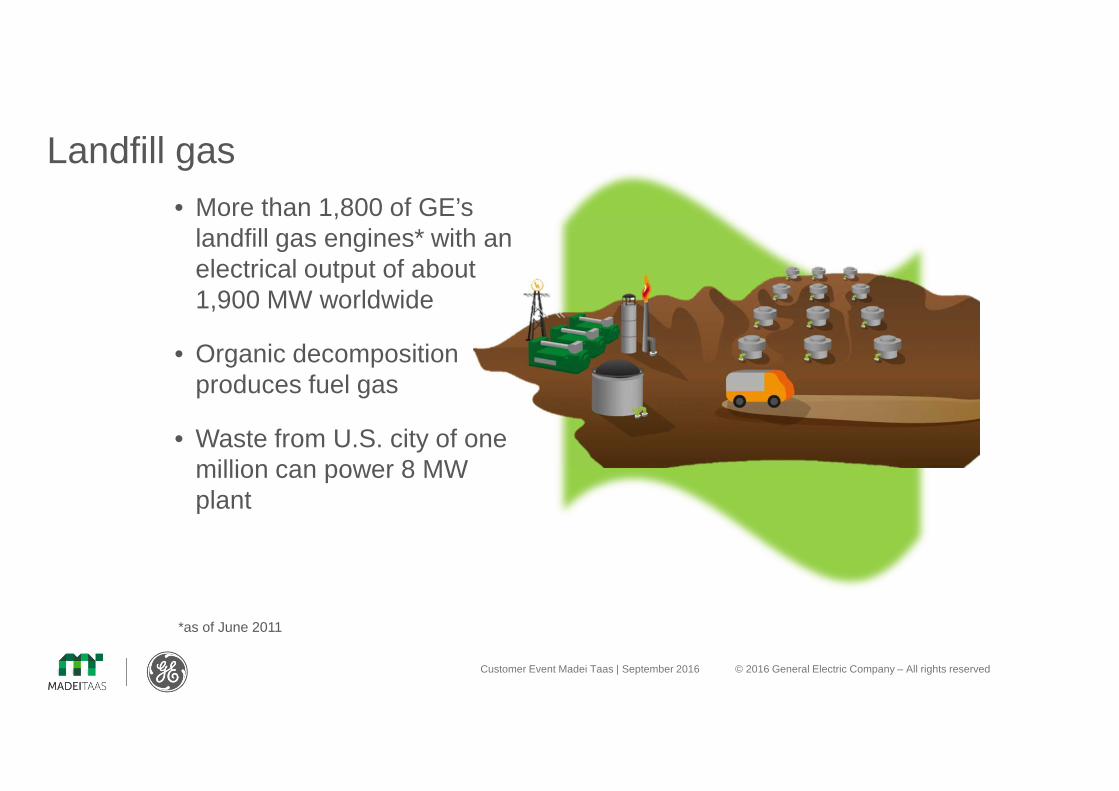
Fuel gasTI 1000 - 0300 Electrical Integration
TI 2108 – 0024f
Interfaces / Plant integration
Customer Event Madei Taas | September 2016 © 2016 General Electric Company – All rights reserved
Fuel Gas Quality and Influence on Engine Operation
Fuel gasTI 1000 - 0300
Interfaces / Plant integration

Customer Event Madei Taas | September 2016 © 2016 General Electric Company – All rights reserved
typical Biogas compositionMain components
Gas component Volume %
CH4 [Vol. %] 45 – 75
CO2 [Vol. %] 25 – 50
O2 [Vol. %] 0 – 2
N2 [Vol. %] 0 – 5
38%
4%
52%
Methan
CO2
N2
O2
H20
contaminations
Gas component concentration
Water [Vol.%] 1 – 7
NH3 [ppm] 0 – 500
H2S [ppm] 0 – 6,000
Siloxane [ppm] 0 - 10

Customer Event Madei Taas | September 2016 © 2016 General Electric Company – All rights reserved
Ball valve Fine filter 3µm
Pre pressure regulator
Double solenoid valve and leak control
Zero pressure regulator
Gas train
3µm safety filter = standard scope
• Polypropylene filter (3µm) for wet gases
Pre-pressure regulator = standard scope
• smoothens pressure fluctuations

Customer Event Madei Taas | September 2016 © 2016 General Electric Company – All rights reserved
Important for dimensioning of gas train• Standard:
– 80 - 200 mbar (prechamber gas pressure Type 6: 4-5.5 barg)
higher/lower gas pressure on request
max. gas pressure fluctuation <10 mbar/sec.
� condensate in gas train => pressure drops �
� condensate trap, continuously upward/downward pipes
� blower with bypass pressure control valve
Gas pressure

Customer Event Madei Taas | September 2016 © 2016 General Electric Company – All rights reserved
Fuel gas requirements TI 1000–0300
• Gas temperature < 40°C
� Mixture temperature �
� Limits of gas train materials �
• relative humidity < 80%(at every gas temperature)
� risk of condensation in gas supply �Filter; pressure regulator; gas trains,.....
Condensate in engine/intercooler �
Customer Event Madei Taas | September 2016 © 2016 General Electric Company – All rights reserved
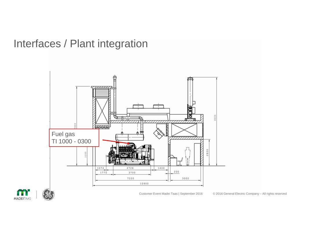
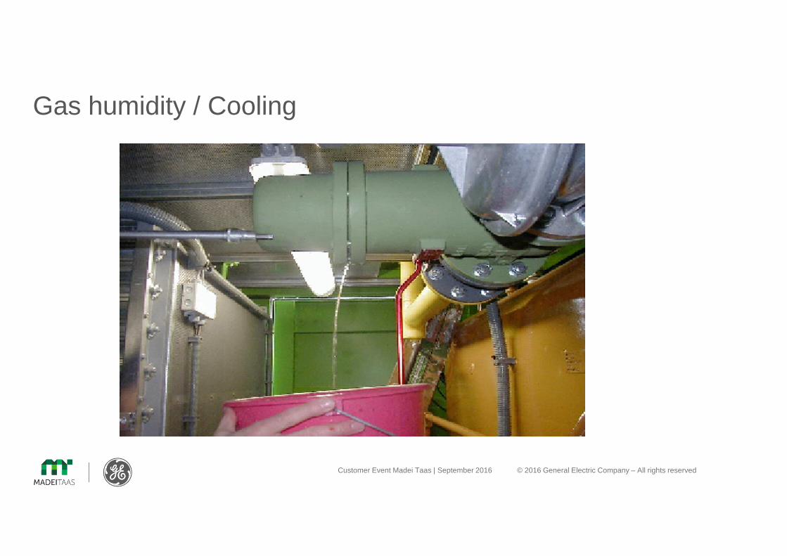
Gas humidity / Cooling

Customer Event Madei Taas | September 2016 © 2016 General Electric Company – All rights reserved
Fuel gas requirements TI 1000-0300Humid ambient
Condensate in throttle / intercooler

Customer Event Madei Taas | September 2016 © 2016 General Electric Company – All rights reserved
Condensate
4Not really a condendsate trap
4Water column
4Condensate can flow down pipe surface
4Rel. humidity in gas not reduced !!!
Water column � not the preferred solution
Condensate trap � preferred solution
4Condensate trap via Entspannung
4Water column
4Rel. humidity in gas not reduced !!!
SymbolSymbol
ground
Condensate tankCondensate trap

Customer Event Madei Taas | September 2016 © 2016 General Electric Company – All rights reserved Distributed Power | August 2014 © 2014 General Electric Company – All
rights reserved
Humidity reduction
4Affects relative humidty; only at low gas temperatures
4Actual water content not changed
4Avoid cooling in down stream
4Cooling effect of soil not guaranteed �depends on soil condition
Cooling via gas pipe Active humidty reduction � better solution
4 Effective reduction of water content4 Reduce risk of having condensate in
the gas system4 Reduces risk of corrosion!
Example
Gas volumen flow 400 Nm3/h
Gas Temperature ON/OFF 40/10 °C
Elec output for cooling system ca.
8 kW
Investment costs ca. 30.000,--€
Condensate trap
Cooling system
Gas compressor
Biogas
Condensate trap
soil Gas compressor

Customer Event Madei Taas | September 2016 © 2016 General Electric Company – All rights reserved
Fuel gas requirements TI 1000–0300
Sulfur
Σ H2S <700 mg/10 kWh• Standard maintenance schedule Biogas/NG
Σ H2S < 1200 mg/10 kWh • Reduced warranty
• Acidification of oil�
• Reduced oil lubrication capacity�
• H2S + H2O � corrosion �
<700mg/10kWh re-calculated to PPM -> means …LHV 6.0kWh/Nm³ (CH4 60%) the H2S should not exceed <293ppm LHV 5.0kWh/Nm³ (CH4 50%) the H2S should not exceed <244ppmLHV 4.0kWh/Nm³ (CH4 40%) the H2S should not exceed <195ppm

Customer Event Madei Taas | September 2016 © 2016 General Electric Company – All rights reserved
Sulfur

Customer Event Madei Taas | September 2016 © 2016 General Electric Company – All rights reserved
Fuel Gas Quality and Influence on Engine OperationExhaust gas systemTI 1100 - 0110/ TI 1100 - 0112
Interfaces / Plant integration
Customer Event Madei Taas | September 2016 © 2016 General Electric Company – All rights reserved
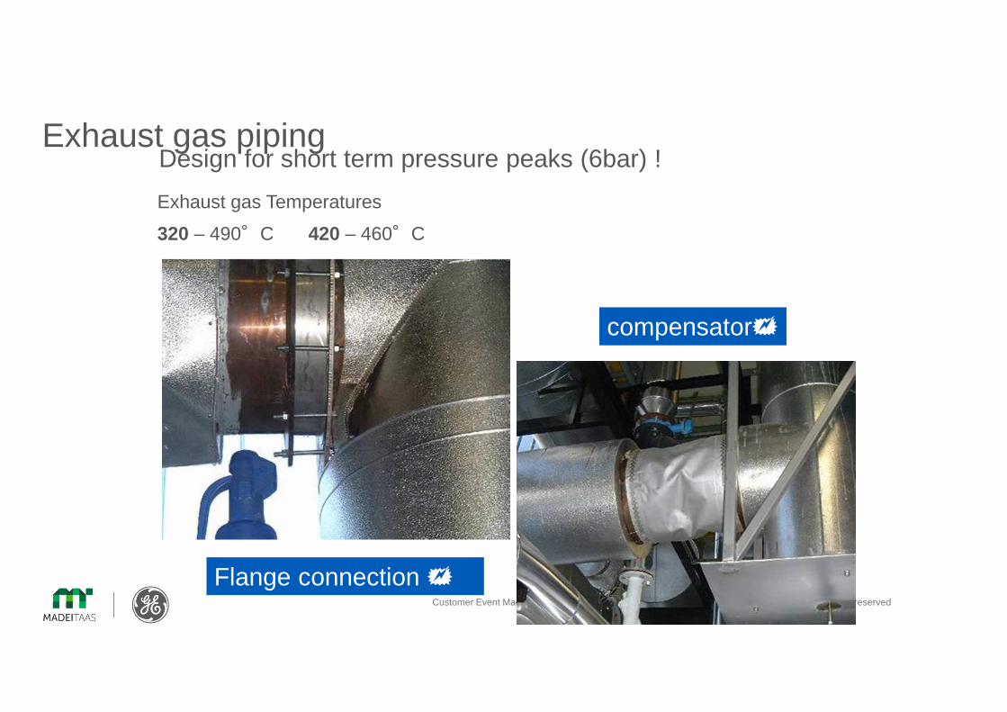
Exhaust gas pipingDesign for short term pressure peaks (6bar) !
Flange connection �
compensator�
Exhaust gas Temperatures
320 – 490°C 420 – 460°C

Customer Event Madei Taas | September 2016 © 2016 General Electric Company – All rights reserved
Fuel Gas Quality and Influence on Engine Operation
Engine installationTI 1000 - 0041
Engine room ventilationTI 1100 - 0110
Interfaces/Plant integration
Engine room TI 1100 - 0110
Customer Event Madei Taas | September 2016 © 2016 General Electric Company – All rights reserved Distributed Power | August 2014 © 2014 General Electric Company – All
rights reserved
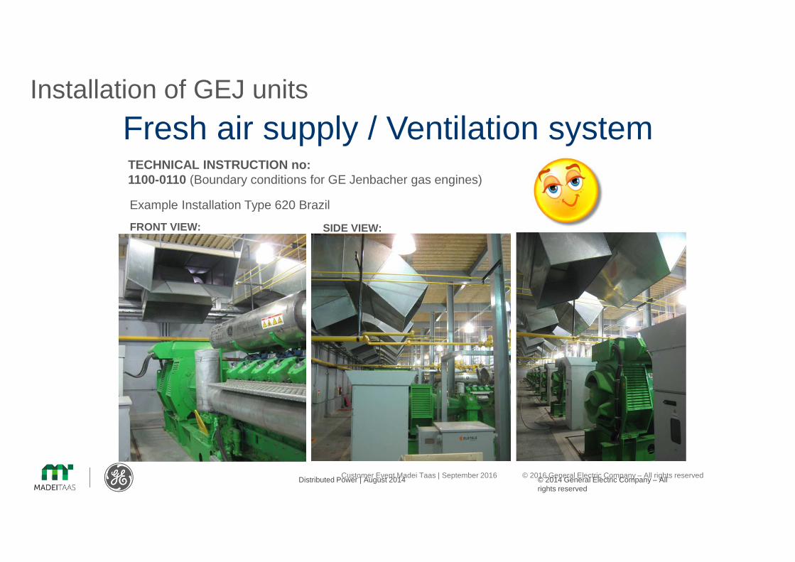
Installation of GEJ units
Fresh air supply / Ventilation systemTECHNICAL INSTRUCTION no: 1100-0110 (Boundary conditions for GE Jenbacher gas engines)
FRONT VIEW: SIDE VIEW:
Example Installation Type 620 Brazil

Customer Event Madei Taas | September 2016 © 2016 General Electric Company – All rights reserved
Radiator types Hot water cooling
• Cost effective & simple
• Footprint
• Low noise
Table cooler V-Type cooler
Customer Event Madei Taas | September 2016 © 2016 General Electric Company – All rights reserved
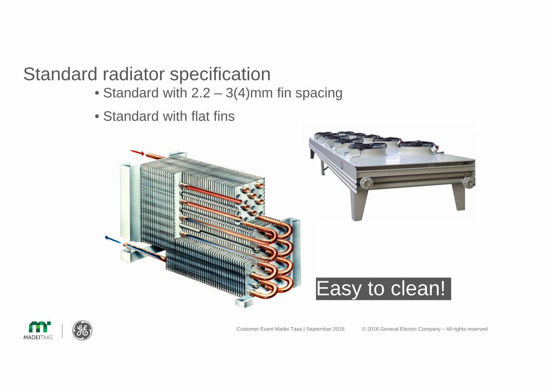
Standard radiator specification• Standard with 2.2 – 3(4)mm fin spacing
• Standard with flat fins
Easy to clean!

Customer Event Madei Taas | September 2016 © 2016 General Electric Company – All rights reserved
Radiator installation

Customer Event Madei Taas | September 2016 © 2016 General Electric Company – All rights reserved
Radiator Layout single unit table cooler
AZ = AA * 0,7 AA = L * BH = Az/(2*(L+B)
FOR TROPICAL COUNTRIES:Especially for tropical countries a additional Pedestal at each Radiatorfoot is required to increasethe air volume. Pedestal should be 400mm

Customer Event Madei Taas | September 2016 © 2016 General Electric Company – All rights reserved
Radiator Layout multiple unit table cooler
BB LL
Space in between radiator:
Max. 80 mm to avoid short circuit ventilation