Embed Size (px)
Citation preview

© 2017 AT&T Intellectual Property. All rights reserved. AT&T and the Globe logo are registered trademarks of AT&T Intellectual Property.
AT&T Switched Ethernet ServiceSM
CUSTOMER DATA FORMAT REQUIREMENTS
AT&T strives to provide a reliable installation and networking experience for our customers. We will do all that we can to ensure the project is completed on time and exceeds our Customer’s expectations. This document describes the specific recommendations, requirements and limitations associated with formatting the Customer data signal so that it can be transported successfully by the AT&T Network.
Note: Additional requirements pertaining to physical room / site preparation requirements are provided in the document: AT&T Switched Ethernet Services - Customer Site Preparation Requirements
1. Customer Network Interface:............................................................................................ 1 2. Customer Provided Equipment (CPE) Choices .................................................................. 2 3. CPE Port Settings ...............................................................................................................2 4. “VLAN-Based” Ports: Configuration and Limitations: ...................................................... 3 5. “Port-Based” Ports: Configuration and Limitations:......................................................... 3 6. MAC (Media Access Control) Address Limitations ........................................................... 4 7. Broadcast, Unicast unknown and Multicast (BUM) Limits .............................................. 5 8. Traffic Shaping ................................................................................................................. 5 9. IP Configuration and Limitations: ..................................................................................... 6 10. Layer 2 Protocol Handling: ............................................................................................. 6 11. Changes to Design / Requirements ................................................................................ 7 12. AT&T Switched Ethernet Broadband Port Connection .................................................. 8
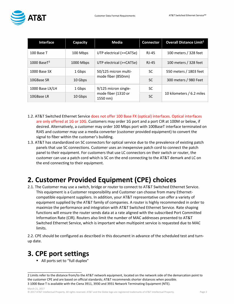
1. Customer Network Interface: 1.1. AT&T Switched Ethernet Service will be terminated according to the guidelines contained in AT&T Switched Ethernet Service - Customer Site Preparation Requirements document. Service will be terminated at the demarcation point and will be either a RJ-45 patch panel for a 100/1000 Base T connection or a fiber patch panel for a 1 Gbps or 10 Gbps optical connection1. The network interface is available in the following choices that need to be selected prior to firm pricing / design: Note all 10G interfaces are Native LAN PHY; we do not support WAN PHY with this service offer.
_______________________________ 1 The Ciena 3911 and 3931 are wall mounted and do not require a separate patch-panel but the associated connectors are consistent with the table above.March 21, 2017
March 21, 2017 © 2017 AT&T Intellectual Property. All rights reserved. AT&T and the Globe logo are registered trademarks of AT&T Intellectual Property. Page 2
AT&T Switched Ethernet ServiceSM Customer Data Format Requirements
1.2. AT&T Switched Ethernet Service does not offer 100 Base FX (optical) interfaces. Optical interfaces
are only offered at 1G or 10G. Customers may order 1G port and a port CIR at 100M or below, if desired. Alternatively, a customer may order 100 Mbps port with 100BaseT interface terminated on RJ45 and customer may use a media converter (customer provided equipment) to convert the signal to fiber within the customer’s building.
1.3. AT&T has standardized on SC connectors for optical service due to the prevalence of existing patch panels that use SC connections. Customer uses an inexpensive patch cord to connect the patch panel to their equipment. For customers that use LC connectors on their switch or router, the customer can use a patch cord which is SC on the end connecting to the AT&T demark and LC on the end connecting to their equipment.
2. Customer Provided Equipment (CPE) choices 2.1. The Customer may use a switch, bridge or router to connect to AT&T Switched Ethernet Service.
This equipment is a Customer responsibility and Customer can choose from many Ethernet-compatible equipment suppliers. In addition, your AT&T representative can offer a variety of equipment supplied by the AT&T family of companies. A router is highly recommended in order to maximize the performance and integration with AT&T Switched Ethernet Service. Rate shaping functions will ensure the router sends data at a rate aligned with the subscribed Port Committed Information Rate (CIR). Routers also limit the number of MAC addresses presented to AT&T Switched Ethernet Service, which is important when multipoint service is requested due to MAC limits.
2.2. CPE should be configured as described in this document in advance of the scheduled test and turn-up date.
3. CPE port settings All ports set to “full duplex”
___________________________ 2 Limits refer to the distance from/to the AT&T network equipment, located on the network side of the demarcation point to the customer CPE and are based on official standards; AT&T recommends shorter distances when possible. 3 1000 Base T is available with the Ciena 3911, 3930 and 3931 Network Terminating Equipment (NTE).
Interface Capacity Media Connector Overall Distance Limit2
100 Base T 100 Mbps UTP electrical (>=CAT5e) RJ-45 100 meters / 328 feet
1000 BaseT3 1000 Mbps UTP electrical (>=CAT5e) RJ-45 100 meters / 328 feet
1000 Base SX 1 Gbps 50/125 micron multi-mode fiber (850nm)
SC 550 meters / 1803 feet
10GBase SR 10 Gbps SC 300 meters / 980 Feet
1000 Base LX/LH 1 Gbps 9/125 micron single-mode fiber (1310 or 1550 nm)
SC 10 kilometers / 6.2 miles
10GBase LR 10 Gbps SC

March 21, 2017 © 2017 AT&T Intellectual Property. All rights reserved. AT&T and the Globe logo are registered trademarks of AT&T Intellectual Property. Page 3
AT&T Switched Ethernet ServiceSM Customer Data Format Requirements
All 100BaseT ports set to 100 Mbps speed and “no auto-negotiation” All 1,000 Mbps (1G) ports (electrical or optical) set to 1000 Mbps speed
1. 1,000BaseT (electrical) ports set to “auto-negotiation on”
2. 1,000 Mbps (optical) ports set to “no auto-negotiation” All 10,000 Mbps (10G) ports set to 10000 Mbps speed and “no auto-negotiation” Frame size limits:
1. 10 Gbps ports will allow up to 9126 MTU 2. All 1 Gbps ports and 100 Mbps ports installed after July 2013 will allow up to 9126 MTU
unless the subscribed PORT CIR is 10 Mbps and below, in which case it may be limited to 1526
3. All others will allow up to 1526 MTU NOTE: The settings for Broadband Ports are detailed in section 12 and may be different from those above.
4. “VLAN-Based” ports: configuration and limitations AT&T Switched Ethernet Service ports can be ordered in either of two configurations: VLAN-Based or “Service Multiplexed” (described in in this section)
Port-based or “all-to-one bundling” (described in section 5) Virtual Local Area Network (VLAN) based port configuration provides “service multiplexing” where the port carries multiple Ethernet Virtual Connections (EVCs) that are identified and switched according to the VLAN ID on the Ethernet Frame. Each EVC may connect to a different (or same) destination and may have different (or same) class of service and bandwidth (Committed Information Rate or CIR).
Customer will assign VLAN Identifiers (CVLAN IDs) to the Ethernet frame and AT&T will route the
frame accordingly Customer may use any CVLAN value from 0002-4089. VLANs 1 and 4090-4095 will be reserved
for AT&T use. Customers may utilize a “double tag” or QinQ if supported by their CPE and AT&T will route on
the first tag while ignoring the 2nd tag There is a maximum number of EVCs associated with each port type:
1. Up to 8 EVCs per 100M Port 2. Up to 64 EVCs per 1 GigE Port 3. Up to 508 EVCs per 10 GigE Port
NOTE: The settings for Broadband Ports are detailed in section 12 and may be different from those above.
5. “Port-Based” ports: configuration and limitations AT&T Switched Ethernet Service ports can be ordered in either of two configurations:
Port-based or “all-to-one bundling” (described in this section) VLAN-Based or “Service Multiplexed” (described in section 4)

March 21, 2017 © 2017 AT&T Intellectual Property. All rights reserved. AT&T and the Globe logo are registered trademarks of AT&T Intellectual Property. Page 4
AT&T Switched Ethernet ServiceSM Customer Data Format Requirements
Port-based refers to an “all to one bundling arrangement” where all of the customer’s traffic (within proscribed limits) is delivered to a single service instance, either an E-Line (point to point) or E-LAN (Multipoint). Traffic is delivered to the distant port(s) without regard to VLAN—AT&T will pass either “tagged” or “untagged” traffic, referring to Ethernet frames that have or do not have VLAN IDs. Even if VLAN IDs are present, AT&T will not route based on those tags.
6. MAC (Media Access Control) address limitations AT&T Switched Ethernet Service uses Ethernet Virtual Connections (EVCs) to connect ports in either point-to-point “E-line” (including point-to-multipoint) or multipoint “E-LAN” arrangements. These ports may be in the same or different LATAs. For point-to-point EVCs between two ports, there are no associated MAC limits. If the EVC is a multipoint EVC arrangement (whether the port is VLAN-based or port-based), the MAC limits specified below will apply. 6.1. MAC Address Limits applicable to multipoint EVC configurations:
Each multipoint EVC on a given port is limited to 250 MAC addresses in the standard configuration. This limit refers to the “source” MAC addresses presented to the port / EVC at this location and does NOT count the destination MACs that are associated with other ports on the multipoint EVC.
A VLAN based port may have multiple multipoint EVCs and each will be allowed up to 250 MAC addresses.
Customers that need to allow for more than 250 MAC addresses per multipoint EVC may subscribe to an optional feature for the port that raises the limit to 500 MACs per multipoint EVC. This feature is subscribed once “per port” and raises the limit on all multipoint EVCs present on that port.
Overflowing MAC Limits: When a frame with an unknown MAC address (caused by exceeding the MAC limits of 250 default or 500 if ordered) arrives, it will not be dropped but will be treated as an Unknown Unicast frame. As such it becomes part of BUM traffic and it will be sent to all the endpoints of the Multi-Point EVC including the endpoint for which it was intended. Such frames are subject to the 2 Mbps BUM traffic limit described in Section 7. If the frame will exceed the 2 Mbps BUM limit associated with the sending EVC, it will be dropped.
Using a router instead of a switch will usually limit the number of MAC addresses presented to the AT&T Switched Ethernet Service port, thereby avoiding issues with MAC limits.
NOTE: The settings for Broadband Ports are detailed in section 12 and may be different from those above.

March 21, 2017 © 2017 AT&T Intellectual Property. All rights reserved. AT&T and the Globe logo are registered trademarks of AT&T Intellectual Property. Page 5
AT&T Switched Ethernet ServiceSM Customer Data Format Requirements
7. Broadcast, Unicast unknown and Multicast (BUM) limitations Broadcast, Unicast unknown and Multicast (BUM) traffic cause a single frame to be replicated to all ports in the associated EVC.
Broadcast Traffic – refers to Ethernet frames that are forwarded to all nodes on the network using the broadcast Ethernet address
Unicast unknown - Unknown unicast traffic consists of unicast packets with unknown destination MAC addresses. By default, the switch floods these unicast packets to all ports that are members of the EVC.
Multicast Traffic – refers to Ethernet frames that are forwarded, in a point to multipoint fashion, across the network to multiple recipients that belong to groups that are identified using any of the multicast Ethernet addresses defined by the Internet Assigned Numbers Authority (IANA) as Internet Multicast.
BUM traffic can cause problems in the customer and/or the AT&T network if not limited appropriately. Continuous and unpredicted floods of BUM traffic can use substantial network bandwidth to the point of overloading the network or port’s capacity and is a significant security risk. Therefore AT&T limits BUM traffic as follows:
7.1. Point to point EVCs will have no limits associated with BUM traffic; BUM traffic can go up to the specified EVC CIR
7.2. Multipoint EVCs will be limited to two (2) Mbps of combined BUM traffic on each multipoint EVC on a given port. Note that this limit applies to the port originating the BUM traffic, not the ports receiving the BUM traffic. Customer should enable BUM controls in their router to avoid unexpected dropped packets due to AT&T enforcement of this limit.
7.3. Enhanced Multicast is a per-port feature that allows for higher BUM limits to be set on the EVC(s) associated with that port. NOTE: The settings for Broadband Ports are detailed in section 12 and may be different from those above.
8. Traffic shaping AT&T Switched Ethernet Service offers flexible configuration options including the ability to set bandwidth (Committed Information Rate or CIR) according to the needs of the applications using the connection. The CIR is specified in two related ways: Port CIR: The CIR set for the physical port is referred to as Port CIR and a variety of CIR choices are offered per port size, ranging from 2 Mbps to 10 Gbps. The Port CIR can never exceed the physical port capacity (i.e., a 100 Mbps port can have a maximum 100 Mbps CIR, and a 1 Gbps port can have up to 1 Gbps CIR, etc.).

March 21, 2017 © 2017 AT&T Intellectual Property. All rights reserved. AT&T and the Globe logo are registered trademarks of AT&T Intellectual Property. Page 6
AT&T Switched Ethernet ServiceSM Customer Data Format Requirements
EVC CIR: There is also a CIR associated with the Ethernet Virtual Connection(s) (EVCs) associated with each port which can be any increment of 1 Mbps up to the maximum available Port CIR. For “port-based” ports, there is only one EVC. For “VLAN-Based” ports
there may be multiple EVCs (see EVC limits section). The sum of the EVC CIRs cannot exceed the Port CIR. AT&T 4 byte overhead: AT&T adds a 4 byte “S-tag” to all Ethernet frames at network ingress. This tag is used to route traffic in the AT&T network and is removed by AT&T at the egress. These 4 bytes per frame should be included when calculating the required CIR for the connection and associated rate shaping and can be especially significant when small frame sizes are transmitted. 8.1. AT&T Switched Ethernet Service will enforce these CIR limits on bandwidth entering and exiting the network. Packets presented in excess of the CIR for that connection will be dropped randomly.
8.2. Customer should enable Traffic Shaping on the Customer Provided Equipment (CPE) switch or router to ensure maximum throughput efficiency by avoiding dropped packets due to AT&T Switched Ethernet Service CIR enforcement. Most routers on the market should support traffic shaping and AT&T representatives may be able to recommend such routers available for purchase from AT&T family of companies.
8.3. Traffic shaping is especially critical whenever the CIR is lower than the physical interface. For example, a 100 Mbps port may subscribe to a 50 Mbps CIR. Without rate shaping, the CPE will generate traffic at the rate of 100 Mbps. Therefore customers that do not use rate shaping should subscribe to CIR rates that match the port speed (100 Mbps, 1 Gbps and 10 Gbps). NOTE: The settings for Broadband Ports are detailed in section 12 and may be different from those above.
9. IP Configuration and limitations 9.1. AT&T Switched Ethernet Service will not: Assign an Internet Protocol (IP) address as part of the AT&T Switched Ethernet Service Enable Cisco Discovery Protocol (CDP) to or from the AT&T Switched Ethernet Service port Enable UniDirectional Link Detection (UDLD) Enable keep-alive
10. Layer 2 protocol handling Port-based service: L2 protocols will be carried transparently. VLAN-based service: L2 protocols will be carried transparently as long as they are tagged with
the agreed to CVLAN (customer VLAN ID); otherwise they will be dropped. Specific protocols and handling are described in the table below:

March 21, 2017 © 2017 AT&T Intellectual Property. All rights reserved. AT&T and the Globe logo are registered trademarks of AT&T Intellectual Property. Page 7
AT&T Switched Ethernet ServiceSM Customer Data Format Requirements
Protocol Name
Port-based Port (tagged & untagged)
VLAN-based Port (tagged)
VLAN-based Port (untagged)
0180C2000000 0180C200000F
Fwd Drop1 Drop
0180C2000010 0180C200001F
Fwd Fwd Drop
0180C2000020 0180C200002F
Fwd Fwd Drop
RSTP Fwd Drop1 Drop
LACP Fwd Drop1 Drop
LACP Marker Fwd Drop1 Drop
OAM Fwd Drop1 Drop
802.1x Fwd Drop1 Drop
LLDP Fwd Drop 1 Drop
GARP Fwd Fwd Drop
GARP BLOCK Fwd Fwd Drop
GMRP Fwd Fwd Drop
GVRP Fwd Fwd Drop
CISCO PAGP Fwd Fwd Drop
CISCO UDLD Fwd Fwd Drop
CISCO CDP Fwd Fwd Drop
CISCO DTP Fwd Fwd Drop
CISCO VTP Fwd Fwd Drop
CISCO PVST Fwd Fwd Drop
CISCO-VLAN BRDG Fwd Fwd Drop
CISCO-UPL FST Fwd Fwd Drop
BRIDGE BLOCK Fwd Fwd Drop
ALL BRDGS BLK Fwd Fwd Drop
BDPU Fwd Fwd Drop
IGMP Fwd Fwd Drop
PIM Fwd Fwd Drop 1 These protocols may be passed or forwarded by some AT&T Switched Ethernet Services. Contact AT&T Account Rep if there is a need to forward this protocol.
NOTE: The settings for Broadband Ports are detailed in section 12 and may be different from those above.
11. Changes to design / requirements If the Customer makes changes to the interface types, quantities, or locations this would invalidate the network design agreed upon between AT&T and the Customer. This change could delay service turn-up as it may result in a change in the type of Network Termination Equipment (NTE) to which the customer will be connecting or the price and configuration of Layer 2 network.

March 21, 2017 © 2017 AT&T Intellectual Property. All rights reserved. AT&T and the Globe logo are registered trademarks of AT&T Intellectual Property. Page 8
AT&T Switched Ethernet ServiceSM Customer Data Format Requirements
12. AT&T Switched Ethernet broadband port connection AT&T Switched Ethernet Service Broadband Port Connections are provisioned over copper ADSL2+ and VDSL2 facilities, with different service characteristics than the AT&T Switched Ethernet Service Basic and PPCOS Port Connections mentioned in the previous sections of this document. These differences are outlined in the following subsections:
12.1. [Broadband Port Connection Only] Customer Network Interface
AT&T Switched Ethernet Service Broadband Port Connection will be terminated according to the guidelines contained in AT&T Switched Ethernet Service - Customer Site Preparation Requirements document. Service will be terminated inside the customer suite.
Interface Capacity Media Connector Overall Distance Limit
10/100/1000 BaseT (auto-negotiate
enabled)
1000 Mbps UTP electrical (>=CAT5e)
RJ-45 100 meters / 328 feet
The AT&T network equipment placed at the customer premises may be installed on a desktop or wall mounted, and does not require a separate patch-panel. Limits refer to the distance from/to the AT&T network equipment, located on the network side of the demarcation point to the customer CPE and are based on official standards; AT&T recommends shorter distances when possible. Auto-negotiation MUST be enabled on the customer CPE. 12.2. [Broadband Port Connection Only] Customer Provided Equipment (CPE) Choices This equipment is a Customer responsibility and Customer can choose from many Ethernet-compatible equipment suppliers. In addition, your AT&T representative can offer a variety of equipment supplied by the AT&T family of companies. A router is highly recommended in order to maximize the performance and integration with AT&T Switched Ethernet Service. Rate shaping functions will ensure the router sends data at a rate aligned with the subscribed Port Speed Tier. Routers also limit the number of MAC addresses presented to AT&T Switched Ethernet Service. Because Broadband Port Connection has more stringent MAC address limits than AT&T Switched Ethernet Service Basic and PPCOS Port Connections, the use of Ethernet bridge or switch CPE is strongly discouraged. CPE should be configured as described in this document in advance of the scheduled test and turn-up date. 12.3. [Broadband Port Connection Only] CPE Port Settings
Port set to “full duplex” Port set to “auto-negotiation on”

March 21, 2017 © 2017 AT&T Intellectual Property. All rights reserved. AT&T and the Globe logo are registered trademarks of AT&T Intellectual Property. Page 9
AT&T Switched Ethernet ServiceSM Customer Data Format Requirements
Frame size limit of 1522 byte MTU
12.4. [Broadband Port Connection Only] VLAN-Based Port Configuration and Limitations Virtual Local Area Network (VLAN) based port configuration provides “service multiplexing” where the port carries multiple Ethernet Virtual Connections (EVCs) that are identified and switched according to the VLAN ID on the Ethernet Frame. Each VLAN may connect to a different (or same) destination. EVCs terminating on a Broadband Port Connection can only use Broadband Basic CoS at that port. Each EVC can carry the full bandwidth of the Broadband Port Connection; therefore, the total bandwidth of all EVCs on a single port may exceed the selected Broadband Speed Tier of that port if not properly shaped. However, the aggregate transmission of traffic cannot exceed the Broadband Port Connection Speed Tier and any excess traffic will be randomly dropped. In addition, overrunning the port with traffic could cause the Arris NM55 placed at the Customer premises to become unresponsive (see Section 12.10). An EVC connecting a Broadband Port Connection to a Basic or a PPCOS Port Connection will still be required to assign an EVC CoS and CIR at the end of the EVC terminating on the Basic or PPCOS Port Connection. The Customer-owned equipment will be responsible for allocating an appropriate amount of bandwidth to each EVC terminating on the local port to meet the needs of the Customer, and to shape traffic so as not to overrun the amount of traffic that the local or foreign end port(s) can receive, whether the foreign end port(s) be a Broadband, Basic, or PPCOS Service Arrangement.
Customer will assign VLAN Identifiers (CVLAN IDs) to the Ethernet frame and AT&T will route the frame accordingly
Customer may use any CVLAN value from 0002-4089. Customers may utilize a “double tag” or QinQ if supported by their CPE and AT&T will
route on the first tag while ignoring the 2nd tag There is a maximum number of 8 EVCs associated with a Broadband Port Connection.
12.5. [Broadband Port Connection Only] “Port-Based” Ports: Configuration and Limitations AT&T Switched Ethernet Service ports can be ordered in either of two configurations:
Port-based or “all-to-one bundling” (described in this section) VLAN-Based or “Service Multiplexed” (described in section 4)
Port-based refers to an “all to one bundling arrangement” where all of the customer’s traffic (within proscribed limits) is delivered to a single service instance, either an E-Line (point to point) or E-LAN (Multipoint). Traffic is delivered to the distant port(s) without regard to VLAN—AT&T will pass either “tagged” or “untagged” traffic, referring to Ethernet frames that have or do not have VLAN IDs. Even if VLAN IDs are present, AT&T will not route based on those tags. 12.6. [Broadband Port Connection Only] MAC (Media Access Control) Address Limitations
AT&T Switched Ethernet Service can be configured in either point-to-point (including point-to-multipoint) or multipoint arrangements. On both point-to-point and multipoint configurations (VLAN-based or port-based), Broadband Ports will be limited to 64 MAC addresses. It is highly recommended that Customer interface to a Broadband Port with a router instead of a switch in order to reduce the

March 21, 2017 © 2017 AT&T Intellectual Property. All rights reserved. AT&T and the Globe logo are registered trademarks of AT&T Intellectual Property. Page 10
AT&T Switched Ethernet ServiceSM Customer Data Format Requirements
number of MAC addresses presented to the AT&T Switched Ethernet Service port, and thereby avoid issues with MAC limits. 12.7. [Broadband Port Connection Only] Broadcast, Unicast unknown and Multicast (BUM) Limits Broadcast, Unicast unknown and Multicast (BUM) traffic causes a single frame to be replicated to all ports in the associated VLAN.
Broadcast Traffic – refers to Ethernet frames that are forwarded to all nodes on the network using the broadcast Ethernet address
Unicast unknown - Unknown unicast traffic consists of unicast packets with unknown destination MAC addresses. By default, the switch floods these unicast packets that are traveling in a VLAN to all interfaces that are members of the VLAN.
Multicast Traffic – refers to Ethernet frames that are forwarded, in a point to multipoint fashion, across the network to multiple recipients that belong to groups that are identified using any of the multicast Ethernet addresses defined by the Internet Assigned Numbers Authority (IANA) as Internet Multicast.
BUM traffic can cause problems in the customer and/or the AT&T network if not limited appropriately. Continuous and unpredicted floods of BUM traffic can use substantial network bandwidth to the point of overloading the network’s or port’s capacity and is a significant security risk. Therefore AT&T limits BUM traffic as follows:
12.7.1. Point to point configurations will have no limits associated with BUM traffic; BUM traffic can go up to the specified ingress (upload) port speed.
12.7.2. Multipoint configurations (VLAN-based or port-based) will be limited to two (2) Mbps of combined BUM traffic on a given port. Note that this limit applies to the port originating the BUM traffic, not the ports receiving the BUM traffic. Customer should enable BUM controls in their router to avoid unexpected dropped packets due to AT&T enforcement of this limit.
12.7.3. Enhanced Multicast is a per-port feature that allows for higher BUM limits to be set on the port. The Enhanced Multicast feature for Broadband Ports applies only to Broadband Speed Tiers of 24 Mbps Downstream – 3 Mbps Upstream, 45 Mbps Downstream – 6 Mbps Upstream, and 4 Mbps Downstream – 4 Mbps Upstream.
12.8. [Broadband Port Connection Only] Traffic Shaping
AT&T Switched Ethernet Service offers flexible configuration options including the ability to set bandwidth (Speed Tier) according to the needs of the applications using the connection. The Speed Tier represents the maximum bandwidth available on the Broadband Port, ranging from 3 Mbps download x 1 Mbps upload up to 45 Mbps download x 6 Mbps upload. Broadband Ports also support two symmetric speeds of 2 Mbps and 4 Mbps, where the download and upload speeds are the same.

March 21, 2017 © 2017 AT&T Intellectual Property. All rights reserved. AT&T and the Globe logo are registered trademarks of AT&T Intellectual Property. Page 11
AT&T Switched Ethernet ServiceSM Customer Data Format Requirements
AT&T 4 byte overhead: AT&T adds a 4 byte “S-tag” to all Ethernet frames at network ingress. This tag is used to route traffic in the AT&T network and is removed by AT&T at the egress. These 4 bytes per frame should be included when calculating the required CIR for the connection and associated rate shaping and can be especially significant when small frame sizes are transmitted.
12.8.1. AT&T Switched Ethernet Service will enforce traffic to the Broadband Port Speed Tier on bandwidth entering and exiting the network. Packets presented in excess of the bandwidth speed for that connection will be dropped randomly.
12.8.2. Customer should enable Traffic Shaping on the Customer Provided Equipment (CPE) switch or router to ensure maximum throughput efficiency by avoiding dropped packets due to AT&T Switched Ethernet Service bandwidth enforcement. Most routers on the market should support traffic shaping and AT&T representatives may be able to recommend such routers available for purchase from the AT&T family of companies.
12.8.3. Failure to shape traffic on a Broadband Port could result in the AT&T network equipment at the customer premises becoming unresponsive due to CPU overutilization.
12.8.4. Broadband Ports police bandwidth on the port instead of the EVC; therefore, each EVC terminating on a Broadband Port is capable of transmitting the full bandwidth of the Broadband Speed Tier. The Customer is responsible for allocating port bandwidth between EVCs and ensuring that the aggregate transmission rate of all EVCs on that port does not exceed the Broadband Speed Tier. The Customer must shape traffic so as not to exceed the amount of traffic that the local Broadband Port and the distant end port(s) can receive.
12.9. [Broadband Port Connection Only] IP Configuration and Limitations:
AT&T Switched Ethernet Service Broadband Ports will not: Assign an Internet Protocol (IP) address as part of the AT&T Switched Ethernet
Service Enable Cisco Discovery Protocol (CDP) to or from the AT&T Switched Ethernet
Service port Enable UniDirectional Link Detection (UDLD) Enable keep-alive
12.10. [Broadband Port Connection Only] Layer 2 Control Protocol Handling: Specific protocols and handling by Broadband Ports are described in the table below:

March 21, 2017 © 2017 AT&T Intellectual Property. All rights reserved. AT&T and the Globe logo are registered trademarks of AT&T Intellectual Property. Page 12
AT&T Switched Ethernet ServiceSM Customer Data Format Requirements
Protocol Name
Port-based Port (tagged & untagged)
VLAN-based Port (tagged) VLAN-based Port (untagged)
0180C2000000 0180C200000F
00 – Fwd 01 – Drop* 02 – Drop* 03 – Drop*
04-0F – Drop*
00 – Fwd 01 – Drop* 02 – Drop* 03 – Drop*
04-0F – Drop*
Drop
0180C2000010 0180C200001F
10-1F - Fwd 10-1F - Fwd Drop
0180C2000020 0180C200002F
20-2F - Fwd 20-2F - Fwd Drop
RSTP Fwd Fwd Drop
LACP Drop* Drop* Drop
LACP Marker Drop* Drop* Drop
OAM Drop* Drop* Drop
802.1x Drop* Drop* Drop
LLDP Drop* Drop* Drop
GARP 20-2F - Fwd 20-2F - Fwd Drop
GARP BLOCK 20-2F - Fwd 20-2F - Fwd Drop
GMRP Fwd Fwd Drop
GVRP Fwd Fwd Drop
CISCO PAGP Fwd Fwd Drop
CISCO UDLD Fwd Fwd Drop
CISCO CDP Fwd Fwd Drop
CISCO DTP Fwd Fwd Drop
CISCO VTP Fwd Fwd Drop
CISCO PVST Fwd Fwd Drop
CISCO-VLAN BRDG Fwd Fwd Drop
CISCO-UPL FST Fwd Fwd Drop
BRIDGE BLOCK 00 – Fwd 01 – Drop
02 – Drop* 03 – Drop*
04-0F – Drop*
00 – Fwd 01 – Drop
02 – Drop* 03 – Drop*
04-0F – Drop*
Drop
ALL BRDGS BLK 10-1F - Fwd 10-1F - Fwd Drop
BDPU Fwd Fwd Drop
IGMP Fwd Fwd Drop

March 21, 2017 © 2017 AT&T Intellectual Property. All rights reserved. AT&T and the Globe logo are registered trademarks of AT&T Intellectual Property. Page 13
AT&T Switched Ethernet ServiceSM Customer Data Format Requirements
PIM Fwd Fwd Drop
*Note: Certain AT&T Switched Ethernet Service Broadband Port Connections may have the capability to pass or forward these protocols based upon the network equipment used in the provisioning of the circuit; however, given the limited availability of this equipment in AT&T’s network, the Customer should generally expect the L2 Protocol Handling to be in compliance with the table above.
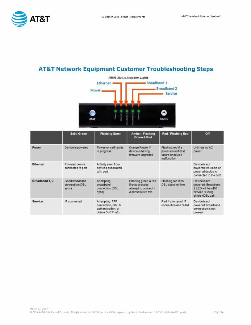
12.11. [Broadband Port Connection Only] Arris NM55 Troubleshooting: The AT&T network equipment placed at the customer premises could become unresponsive if:
Customer Provided Equipment (CPE) is not traffic shaping to the Speed Tier (i.e. 3/1M, 2M) and overruns the port with traffic, or
The customer’s CPE attempts to send traffic while the AT&T network equipment is going through its boot cycle (i.e. during installation or after a power cycle)
In the event that the AT&T network equipment becomes unresponsive, take the following actions:
March 21, 2017 © 2017 AT&T Intellectual Property. All rights reserved. AT&T and the Globe logo are registered trademarks of AT&T Intellectual Property. Page 14
AT&T Switched Ethernet ServiceSM Customer Data Format Requirements

March 21, 2017 © 2017 AT&T Intellectual Property. All rights reserved. AT&T and the Globe logo are registered trademarks of AT&T Intellectual Property. Page 15
AT&T Switched Ethernet ServiceSM Customer Data Format Requirements
12.12. [Broadband Port Connection Only] RFC 2544 Testing: In the event that the customer chooses to perform RFC 2544 testing, the AT&T network equipment packet processing capacity may not support full throughput when consecutive small frames are transmitted from the customer CPE and/or test set to the AT&T network equipment: 2M, 4M, 3/1M, 6/1M, 12/1.5M, 18/1.5M, 24/3M, 45/6M may fail customer RFC 2544
testing on frame sizes < 256 Bytes 45/6M may fail customer RFC2544 testing on frame sizes < 512 Bytes This should not negatively impact customer throughput for real-world applications, even if
they are using VoIP. The VOIP packets will be a small percentage of the overall bandwidth. Most of the packets will be the larger data packets. If the customer ran twenty simultaneous VoIP calls using G.711 or G.729 compression, the mix of data and voice would still have an average packet size of ~ 300B – 318B. For example, the following table shows expected throughput on 45/6M of 98% upspeed and 99% throughput on downspeed for G.711 and G.729 with 20 simultaneous calls.
Note: Additional requirements pertaining to physical room / site preparation requirements are provided in the document: AT&T Switched Ethernet Services - Customer Site Preparation Requirements