Embed Size (px)
Citation preview

Phone: (800) 231-7005
Fax: (800) 243-3934
www.SiliconeDynamics.net

INTRODUCTION
Thank you for your interest in Silicone Keypad Products. This booklet has been designed to offer basic information on Silicone Keypad technology and to provide some basic design constraints to ease the flow of your new project.
This guide provides basic design rules and information needed to help designers during the initial stage of design. It also shows various technologies used in keypad manufacturing to serve the various needs of customers.
Conductive silicone rubber keypads were originally developed for the electronics industry as an economical design alternative to discrete switches. 30 years later they are the most widely used form of switch technology, mainly due to their reliability, long life and multitude of design opportunities.
Silicone Dynamics has over 10 years experience in silicone keypad design and manufacturing.
Silicone Dynamics uses many different technologies and offers design support to small and medium size businesses in the electronics market. With support available throughout the USA we can respond to inquiries quickly and support your design team with Silicone, Membrane discrete keypad switch solutions, and custom plastic enclosures.
Did you know... VirtuallyAll electronic devices that arepowered by batteries or electriccurrent today rely on silicones!

TABLE OF CONTENTS
1. Material .................................................................................................4
2.Characteristic Features Of Silicone ....................................................5-9
3.Silicone History...............................................................................10-12
4.Silicone Rubber Keyboard Applications .........................................13-14
5.Moulding.........................................................................................15-18
6.Basic Keypad Design .......................................................................19-21
7. Design Considerations ...................................................................22-26
8.Printing ..........................................................................................27-29
9.Terminology ...................................................................................30-31

' -. ,· '· SI SI
' ' ,•, , '· o ~I :; 0 CH3 /. I -, I .•
Si 0 0 r· ..,, , -. I •' I ' ' CH3 ' 0 s S, o ' ' .: I I ' I ' '
CH3 Si 0 0 SI
' I -~1!1 0 SI 0
' ' ' ' '
MATERIALModern society expects technological innovation and product development that will enable us to live
longer, healthier, better lives. Silicones are a fundamental building block that helps make this possible. Silicone rubber is a synthetic material which has the structure shown below.
The polymeric molecular structure of silicone rubbers has a main chain formed of siloxane linkages Si-O. The bond energy of the siloxane linkage Si-O is 106.0 kcal/mole which is much higher than the bond energy 84.9 kcal/mole of the carbon-to-carbon bond C-Co This difference in the bond energies explain the outstanding stability of silicone rubbers in comparison with other organic rubbers. In general, silicone rubber has much better heat resistance, electrical insulation, chemical stability, etc. than organic rubber¹.
The “Silicone-Oxygen” molecular structure provides characteristics that allow the final material to withstand a wide variety of chemical and mechanical degradation as well as serving as a strong dielectric. Silicone synthetic rubber is one of two materials presently being used for switch contacts (the other is a material called EPDM).
Dimenthylpolysiloxane, a typical polymeric constituent of silicone rubbers, has a helical or coiled molecular configuration with a small intermolecular force so that it has high resilience, large compressibility and excellent cold resistance. Furthermore, the outwardly directed methyl groups are able to rotate freely resulting in the unique surface properties of silicones such as water repellence and surface-releasability.
Silicone rubber is odorless and tasteless. It does not cause staining, corrosion or deterioration of other materials with which it comes in contact. Good for FDA-approved applications. Silicone rubber has excellent resistance to many chemicals, fluids and oils commonly encountered in service.
Silicones are a family of polymers that include siloxanes and silanes – compound variations of the natural element silicon. Silicon is the second most common element in Earth’s crust.
CH3
SiO O OSi
CH3
CH3
CH3
¹ The term organic rubber is used to determine materials manufactured with a polymer having a “back bone” consisting predominately of carbon-to-carbon linkage. Natural rubber was the first such material available and is produced from the sap of the rubber tree. Organic rubber, as fabricated in rubber products, combines high strength (tensile and tear) with outstanding resistance to fatigue. It has excellent green strength and tack (the ability to stick to itself and to other materials) which makes it simple to fabricate. The main weakness is its moderate resistance to environmental damage by heat, light and ozone, although this can be an advantage in disposable products like toy balloons and is not a problem in bulky products like bridge bearings where practical experience, that is length of time in service, has shown that degradation is a purely surface phenomenon and is not greater than, and is often less than, the surface damage to the concrete and metal parts of the structure.
Various organic rubber products exhibit properties such as:?Intermediate temperature resistance?High tensile and tear resistance?Oil and fuel resistance?Ozone and weather resistance?Shock absorbency?Low cost
4

5
Heat Resistance
Compared to organic rubbers, silicone rubbers in general have high heat resistance. Silicone rubbers can be used semi-permanently at 150°C (302°F) with almost no change in the properties and can withstand more than 10,000 hours of continued service at 200°C (392°F). With this excellent heat resistance, silicone rubbers are widely used in application requiring heat resistance.
Heat resistance of general purpose silicone rubbers may differ considerably depending on the formulation of the ingredients, selection of the curing agent, etc.
Cold Resistance
Silicone rubbers have excellent cold resistance. Even in extreme cold silicone rubbers can retain their elasticity, where most of other organic rubbers lose their elasticity and become brittle.
Weatherability
Silicone rubbers have excellent Weatherability. While rapid degradation is unavoidable in most organic rubbers under the influence of ozone, produced by corona discharge, silicone rubbers are virtually unaffected by ozone. Moreover, physical properties of silicone rubbers are stable and little changed even by prolonged exposure to ultraviolet light and over weathering conditions.
Electrical Properties
Silicone rubbers have extremely high electrical resistance, 10 14 to 1016 ohm-cm, which is stable over a wide range of temperatures and frequencies. The electrical insulation of silicone rubbers is little affected by moisture or even immersion in water and therefore are widely used as a material for electrical insulation.
Silicone rubbers are highly resistant against corona discharge under high voltage and arc discharge so they are also used as an electrical insulating material under high voltage conditions.
Electrical Conductivity
Silicone rubbers can be electroconductive by compounding with a filer such as carbon. Several grades of electroconductive silicone rubber are available. Applications of electroconductive silicone rubbers include contact points of keyboards, parts in electrical heater elements, parts in antistatic devices, and shielding of high voltage cables.
Radiation Resistance
Although the radiation resistance of dimethyl silicone-based general-purpose silicone rubbers is not particularly high compared to most organic rubbers, methyl phenyl silicone rubbers, formulated from a silicone gum having phenyl groups introduced into the polymer molecules, have greatly improved radiation resistance and are useful as a material for electrical insulation of cables and connectors in atomic power plants.
Silicone rubbers can be used as a radiation-resistant material even at high temperature as high as 200°C (392°F) to 300°C (572°F), where most organic rubbers such as natural rubber can no longer be used due to thermal degradation.
CHARACTERISTIC FEATURES OF SILICONE

6
Thermal Conductivity
Silicone rubber have a thermal conductivity of about 0.5 x 10⁻³ cat/cm-see C. this value is higher than that of most organic rubbers. Thermal conductivity property of silicone rubbers are used in heat-radiator sheets, EMI gasket and heating rollers.
Steam Resistance
Silicone rubbers absorb a maximum of about 1% of water even after prolonged immersion in water. Mechanical and electrical properties of silicone rubbers are little affected by immersion irrespective of water temperature.
Although no degradation is seen in silicone rubbers in contact with steam under normal pressure, pressurized steam may have considerable influences on the properties of silicone rubbers. High pressure steam at 150°C (320°F) or higher causes breakage of the polymeric main chain of the organic polysiloxane so that the properties of the silicone rubber are reduced. This problem can be solved by the improvement in the formulation of the silicone rubber and selection of the proper curing agent and post curing conditions.
Chemical, Oil, and Solvent Resistance
At temperature below 100°C (212°F), the oil resistance of silicone rubber is somewhat inferior to that of nitrile and chloroprene rubbers. At temperature above 100°C (212°F), the oil resistance of silicone rubber is superior to all types of organic rubber.
Silicone rubbers are chemical and solvent resistant as well. Polar organic compounds such as aniline, alcohol, dilute alkaline and acid solutions only slightly affect the properties of silicone rubber exhibiting a maximum swelling of 10 - 15%. Silicon rubber swells when contacted with non-polar solvents such as benzene, toluene, and gasoline but he original properties are quickly restored when the solvents are removed.
Silicone should not be used with highly concentrated strong acid and alkaline solutions because they permanently damage silicone rubber. Other solvents affect the properties of silicone rubber in different ways so it is important to thoroughly test silicone rubber before using it in areas where solvents are being used.
Compression Set
Compression set is critical when rubber is used as a packing material in pressure cookers and other high pressure applications. The compression set of silicone rubber is very low and varies little in temperature from -60C (76F) to 250C (482F). On the other hand, organic rubbers are not suitable for use as packing materials at this extreme temperature.
Bending the Fatigue
Conventional rubbers are generally not as resistant as organic rubbers against dynamic stress such as fatigue by repeated bending. Compounded rubbers are 8 to 20 times as resistant against fatigue by bending compared to conventional grades of silicone rubbers. These silicone rubbers products are used in keyboards in office automation instruments, rubbermade parts of transportation machines, and other applications where flexing and bending are required.

~
cg'""' ~11,•,«I
t Jh1ri.1,.,,!S" ( 01,,1.1111 j,.'.111•
of \lut1•1H
\lt-J\U/t'll\1'111 ! o,,,. ·. t '·"•"''"~ lfol1lm.~' I 1·1,1•!1 ,v .. , i111.-11 ll.-.1d
j U~l\]\
High Tear Strength
General purpose silicone rubbers have a tear strength of about 15 kgf/cm. This relatively low tear strength can be substantially increased by improving the chemical structure of the organopolysiloxane and selecting the proper curing agent and tiller. Several high-strength grades with a tear strength of 30 -50 kgf/cm are available and are widely used for moulding intricately shaped, reverse-taper, and large-sized articles.
Although silicone rubber generally has a lower strength than organic rubber, at high temperature silicone rubber retains its strength whereas organic rubber's strength gradually deteriorates.
Gas Permeability
Thin films of silicone rubbers have somewhat larger permeability to gases and vapours than organic rubber and plastic resin films. Relatively high selectivity of permeability among different gases is also one of the characteristic features of silicone rubber films. By virtue of these unique features, silicone rubber films are promising as a membrane for the separation of gases and liquids.
For example, heart-lung machines and oxygen enrichment equipment are now being developed using silicone rubber films as the gas exchange membrane.
Vibration Absorption
General purpose silicone rubbers have a small loss factor so that they are not recommended as a vibration-proof material. However, several vibration-proof silicone products are available which serve as a vibration-proof material with stability over a temperature range from -50°C (-58°F) to 100°C (212°F).
Transparency and Coloration
In contrast to most organic rubbers colored in black due to the formulation of carbon black as reinforcing filler, silicone rubbers can be highly transparent when the filler compounded for the reinforcement is finely divided silica filler which only slightly affects the transparency inherent in organopolysiloxane gum.
Several high-transparency, high-strength silicone rubber products are used to make various shaped articles such as tubes for and food-processing machines. High-transparency silicone rubber compounds can easily be colored by adding a pigment. Vividly and brilliantly coloured silicone rubber articles can be manufactured.
Non-Stick and Corrosion Resistance
Silicone rubbers are chemically inert and as such are non corrosive to most metals and other materials. Silicone rubbers also have excellent release properties making them ideal for use as fixing rollers in copy machines, rollers in printing presses, sheets, and lost wax processes.
7

Silicone offers advantages over natural and most other synthetics as follows:?Properties unaffected by temperature extremes Environmental durability with excellent resistance to
both heat and low temperature (-55°C - 250°C)1
?Almost no blooming (imperfections caused by liquid catalyst residue)?Non toxic?Carbon impregnated rubber has low resistance?Non carbon rubber has a very high resistance, good insulator
2?Minimum abrasion and high resistance to SO and oxidization even in heavy humidity?Minimum chattering or noise generation due to soft and elastic contact structure.
Features of Silicone Rubber Keypads:?Multicolour designs easily accommodated?Design-in of both Tactile and Linear feedback?Translucent materials available?Water and contamination proofable?Cost effective
One major parameter used to define silicone rubber is material hardness/durometer. This can be defined in either Shore or JIS value. Below is a conversion table for Shore and JIS and general feel it can provide.
Shore A
60
64
65
69
70
74
75
80
85
90
95
JIS
56
60
61
65
66
70
71
75
80
85
90
Feel
Grommets
Rubber shoe heel
Typewriter platen
Engine mounts
Shore A
30
32
35
38
40
43
45
49
50
54
55
59
JIS
29
30
33
35
37
40
42
45
46
50
51
55
Feel
Breast implants
Rubber band
Stress ball
Rubber balls
Rubber tire
Natural Rubber manufacturers use waxes to protect against ozone. When Natural Rubber are in use they flex. Flexing causes the protective waxes to migrate to the surface where they form a physical barrier between the air (ozone and oxygen) and the Natural Rubber polymer. This process...the waxes migrating to the surface of the Natural Rubber during use is called "blooming". When Natural Rubber are not regularly used blooming does not occur. Ozone begins eating away the protective wax and before long reaches the tire polymer. Often by this time, the surface carbon black has lost its ability to protect against UV. With UV light and ozone working in concert, degradation starts. The Natural Rubber dries, checks, and will eventually crack.
³ Effect of Sulfur Dioxide/ Sulfonation on natural rubber -. The Plasticity Retention Index (PRI) is higher after using SO2 gas on the drying process.
8

9
Silicone Material General Specification
Operating temperature -15°C to 80°C
Storage temperature -30°C to 85°C
Operating force (Grams) 50 to 450
Cycle life 100,000 to 20Millon
Contact resistance <100 Ohms
Contact rating @ 5mA 12VDC/0.5sec/20 million cycles
Contact bounce <12m seconds
Insulation resistance >1012Ohms @ 500VDC
Break voltage >25~30 KV/mm
Key color Optional
Key size Optional
Key Shape Optional
Tactile feedback Optional
Printing Color Optional
Conductive Rubber Insulative Rubber
Specific gravity 1.06~1.18 Specific gravity 1.10~1.40
Hardness JIS 70 Hardness JIS 30~90
Tensile strength kg/sm2 58 Tensile strength kg/sm2 50~95
Elongation % 170 Elongation % 100~650
Compression set % 21 Compression set % 10~24
Vol. resistivity Ohm-cm 25 Vol. resistivity Ohm-cm >1012Ohms
The data relating to the standard material used in the manufacture of conductive and Insulative silicone keypads. Additional information on materials with different characteristics to suit specific applications can be obtained from Silicone Dynamics.

10SILICONE HISTORYThe beginning of silicone science starts in nature. Sand, or silica, is the fine residue of quartz rock and is
made up of the two most abundant elements in Earth’s crust – oxygen and silicon. Silicon-based materials have been of technological importance throughout recorded history. Initially, quartz and silica-based stones were fashioned into tools to enhance survival. Later, glass and ceramic technologies developed. The new silicone-based technologies of optics and electronics followed, in response to the changing demands of an evolving world. Today, silicon science continues to evolve in pace with the demanding needs of our society.
Silicone was first isolated and described as an element in 1824 by a Swedish chemist, Jons Jacob Berzelius. An impure form was obtained in 1811. Crystalline silicone was first produced in 1854 using electrolysis.
The First Commercial Era of Silicon-Based Materials (1943-1960)
This period was dominated by the classical siloxane, poly(dimethylsiloxane) fluids, elastomers, and simple methyl and phenyl resins. Poly(dimethylsiloxane) was the backbone of this growing industry and offered a myriad of commercial applications. Its uses included mechanical applications, surface treatments, and cosmetic and biomedical applications in which the unique properties of these materials could be utilized.
1930
Dr. Eugene C. Sullivan, director of research, Corning Glass Co., asks Dr. J. Franklin Hyde to investigate the possibility of developing plastics with the properties of glass. Silicones combine the advantages of both glass and plastics. Glass is silicon-based, making it temperature and moisture-resistant, chemically inert, and dielectric. Plastics are carbon-based, making them strong and able to assume many forms.
The Carnegie - Mellon University Research Group:Dr. McGregor, Dr. Speier, Dr. Warrick, Ruth Zimmerman,Helena Corsello, and Charlie Kohl.
Dr. Eugene C. Sullivan Dr. J. Franklin Hyde

11
1937
Under a Corning Fellowship, Dr. Rob Roy McGregor leads a research team, including Dr. Earl Warrick and Dr. John Speier, to work on silicones at the Mellon Institute, Pittsburgh, Pennsylvania (USA) to investigate possibilities of use of Silicone commercially.
The Third Era: Materials (1980-2000)
Materials, components, and systems are often regarded as separate and sequential levels of integration. But this old paradigm is no longer valid for the development of advanced materials. The commercial opportunities and implications of this blurring distinction are immense for material science and those who practice the art.
1980’s
The introduction of flexible, thin-film conformal coatings allows electronic components to be made smaller and lighter, paving the way for modern cell phones and laptop computers.
The Current Era of Silicone
In addition to the excitement that surrounds our new science is an excitement of vision for new commercial applications. Beyond the ordinary to the extraordinary, silicon-based products provide an advantage in nearly every industry segment of today’s economy. Easily tailored, these materials provide routine features, such as high temperature stability and resistance to aging and chemical assault. These advanced materials also have the ability, depending on the material, to:
• Adhere • Lubricate • Condition • Purify
• Control foam • Wet • Improve appearance • Insulate
• Connect • Protect • Transfer energy • Release
• Mask • Soften • Reconstruct • Conduct
• Deliver • Seal
Did you know... the firstfootprint on the moon was made by
a silicone rubber boot!“That’s one small step for man,
one giant leap for mankind.”In 1969 Silicone Sole makes history
when Neil Armstrong plants his boot,with a silicone rubber sole,
on the moon.

I I I . . -
12
The flexible surface properties of silicon-based materials make them ideal for many applications, including paper and mold release agents, textile modifiers, water repellents, defoaming agents, anticaking aids, corrosion inhibitors, emulsifiers, lubricants, conditioners, and glass enhancers. These are just a few of the thousands of applications for silicon-based products.
Did you know... Because ofits ability to withstand temperature
extremes, Silicone Building Sealant waschosen to restore the Mount Rushmore
memorial in the Black Hills ofSouth Dakota (USA).

13
Imagine what silicones could enable us to do.
Industrial Products
In the last few years the number of applications for rubber keypads in relatively low volume industrial products has increased significantly.
Alongside the lower cost of development and tooling charges, the primary reason for the increases in applications is the creative designs that can be produced. Industrial designers have long since realized the design benefits of working with rubber to create a well designed user interface. In addition the range of tactile responses that can now be engineered into a design help to ensure that a product feels good for a user thus helping the marketing effort of a product.
Mobile Phone
Mobile phone applications have the dominant volume market place for rubber keypads over the recent years. This has lead to significant technical enhancements to provide the visual effects customers required.
These design features include Laser etched keys for better backlighting effects, plastic key tops for more resilient keys and metallic surface finishes. Information on these techniques can be found under design features in this ebook.
Remote Control Keypads
The market for Remote Control keypads has risen to a very high volume over the last 10 years fuelled by their increased use in practically all entertainment products.
Most designs incorporate the use of Flowing Color key coloring and large multi-position navigation keys. Because of their high use patterns most remotes now use specifically developed PC Coating to maintain the key legends.
Computer Keyboard
Silicone Rubber keypads have replaced standard mechanical switches, and in the process reduced the cost of many mainstream computer keyboards.
Keys were developed to give similar response to a mechanical switch thus allowing users to maintain data entry rates.
SILICONE RUBBER KEYBOARD APPLICATIONS

14
Automotive
In the last 10 years automotive manufacturers chose silicone rubber to provide robust tactile response in application such as ICE and Air-conditioning. As the move towards low voltage/current switching within a vehicles wiring system gathers pace tactile rubber elements are replacing traditional mechanical switch elements in main function control buttons.
Did you know...by changing the size or structure ofthe silicone molecule or by adding
different compounds to it,you can enhance or change
the way it behaves!

c.. - .. rt
" _ CaVTtM
. ·-·-
.t
15
Molding is a repetitive process in which material is melted and injected into a mold cavity where the article is cooled down. After cooling, the mold opens and the finished/semifinished article is ejected. Molding is a process that is used for high volume parts, complex variable geometries, and when tight tolerances are required. The process of molding silicone rubbers is a very complex process, and involves much more variables than when dealing with thermoplastics. Silicone rubbers have to be perfectly mixed, injected, and cured inside the mold cavity immediately after injection. Mold cavities and runners have to be designed to not only heat the material in the part cavity. Sufficient heating time has to be provided to the parts to assure full conversion. Parts which are not fully cured will not have optimal properties. Below is few molding processes used for silicone.
Compression
A piece of uncured Silicone rubber of the right weight is placed between two halves (-150°C) of a mold. This mold is closed in a press and the rubber is forced to fill up the cavities in the mold. The rubber gains heat from the heated mold and cures. After a certain cycle time, the part can be removed.
Transfer
Uncured Silicone Rubber is forced through a "runner system" mold with small gate point by a plunger. The rubber then fills the cavities of the and the rubber begins to cure in the heated mold. Once cycle time is reached, the part is removed from the mold.
Liquid Injection Molding
The most commonly used and very economical process. Low viscosity liquid silicone material is injected into the cavity in the mold much similar to that of plastic injection. Injection pressures for molding LSRs can vary from approximately 200 to 1200 psi, depending on process requirements, with the majority of applications requiring pressures from 300 to 700 psi. It is important to note that liquid silicone rubber is slightly compressible, and that injection molding with this type of material is somewhat like molding a spring. The compressibility of the product depends on the type of silicone fluid and on the amount of filler used in the particular LSR formulation.
Physical properties of finished products made from LSR will be affected by changes in molding conditions, especially injection pressure. Shrinkage of finished parts is normal and is also related to injection pressure. In general, higher injection pressure results in lower part shrinkage. It is for this reason that LSR suppliers provide a range of shrinkage values with their products.
SILICONE MOLDING
Molding
Molding

Coo~ rur,ne"j,
Cav,ty
LSR Process
16
Prior to vulcanization, the LSR is injected into the cavity at room temperature. As the material is subjected to shear and heat in the runner system, the temperature increases but is still much lower than the cavity temperature. Once the cavity is filled and the heat of the LSR begins to increase at a rapid rate, the material is prone to expansion. At this point, the clamp pressure should exceed the cavity pressure, but backrinding may occur in the gate area as the expanding elastomer is forced out of the runner system.
This problem normally occurs at high vulcanization temperatures with parts that have large cross sections. There are three basic remedies in such cases: to decrease the injection pressure, to decrease the vulcanization temperature, or to move the gate location to a smaller cross section in the tool. Although the first two recommendations are easily accomplished, they negatively affect the productivity of the process and also influence the final shrink size. For these reasons, the third option may be the best choice. In moving the gate to a smaller cross section, the objective is to fill the cavity and vulcanize the rubber in the thin sections first. This approach allows for more sealing around the gate area while the large cross section is still vulcanizing.
To facilitate removal of parts in both manual and automated operations, it is often desirable to ensure that the part sticks to a specific side of the mold as the mold opens. In some cases, if the mold temperature between the fixed and the movable platen varies by 5° to 10°F, the part tends to stick to the surface with the lower temperature. Note that as the variance increases, stress on the guide pins also increases, which could result in premature wear on the guide pins and bushings.
--0 coos in. 0 0003 · . t ~-Tj:::;:;~
17
Vulcanization time is the next important consideration. As with other aspects of fabrication, the individual process will determine if it is permissible to adjust vulcanization time. Under normal conditions, the part is vulcanized sufficiently to allow for easy removal from the mold without any deformation. However, if the final dimensions or physical properties of the part might be compromised during removal, a postcure may be appropriate. Unlike peroxide postcures that drive off residual materials from rubber, the addition-curing process for LSRs is used to optimize physical properties such as tensile strength, modulus, elongation, and durometer. The length of time and temperature required for postcure will depend on the precure characteristics of the part and the targeted properties. The curing temperature most commonly used in the industry is 175°C, with cure time depending on desired final properties. The curing oven should be monitored for uniform heating, since hot spots or poor air circulation may cause uneven curing, which can result in inconsistent part performance.
When a postcure for LSR components is implemented, it is important that the parts reach the temperature uniformly and that no stress is applied. Parts should be individually placed on an open-mesh tray so that they do not touch. If a mesh version is not available to facilitate air movement around the parts, a heat-conductive tray (e.g., PTFE-coated aluminum) is an acceptable alternative.
Tool Design
Several aspects of tool design can have an impact on cavity pressure and vulcanization temperature within the tool. Even given successful filling, it is still possible that end products may not meet specifications and that additional work on the tooling may be necessary. These potential problems can be avoided by improved tool design that focuses on cavity pressure and on attaining a uniform vulcanization temperature.
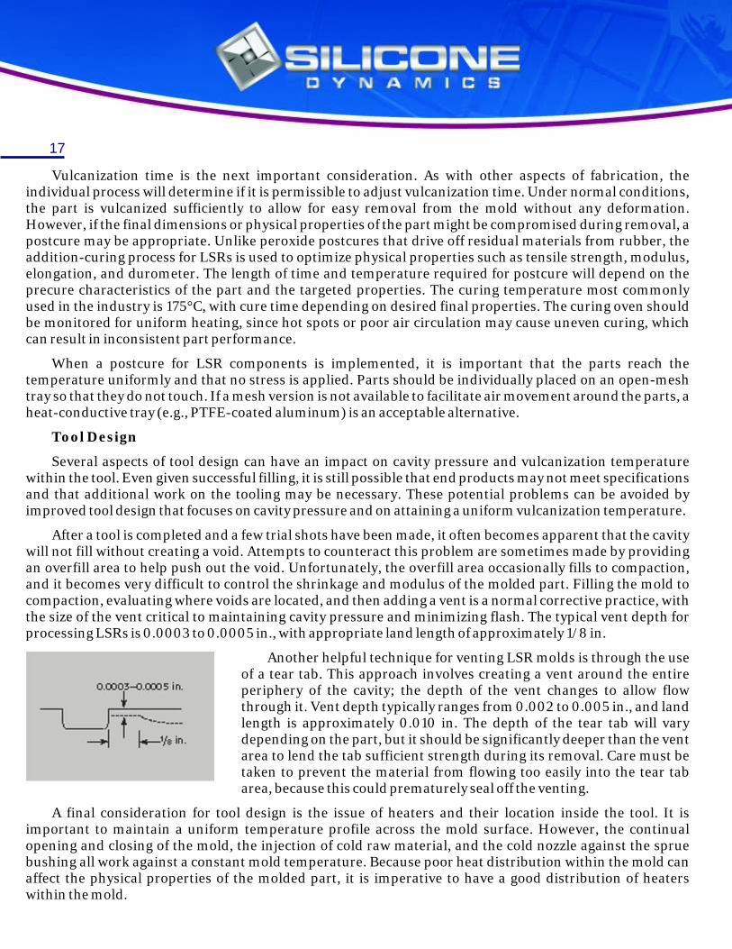
After a tool is completed and a few trial shots have been made, it often becomes apparent that the cavity will not fill without creating a void. Attempts to counteract this problem are sometimes made by providing an overfill area to help push out the void. Unfortunately, the overfill area occasionally fills to compaction, and it becomes very difficult to control the shrinkage and modulus of the molded part. Filling the mold to compaction, evaluating where voids are located, and then adding a vent is a normal corrective practice, with the size of the vent critical to maintaining cavity pressure and minimizing flash. The typical vent depth for processing LSRs is 0.0003 to 0.0005 in., with appropriate land length of approximately 1/8 in.
Another helpful technique for venting LSR molds is through the use of a tear tab. This approach involves creating a vent around the entire periphery of the cavity; the depth of the vent changes to allow flow through it. Vent depth typically ranges from 0.002 to 0.005 in., and land length is approximately 0.010 in. The depth of the tear tab will vary depending on the part, but it should be significantly deeper than the vent area to lend the tab sufficient strength during its removal. Care must be taken to prevent the material from flowing too easily into the tear tab area, because this could prematurely seal off the venting.
A final consideration for tool design is the issue of heaters and their location inside the tool. It is important to maintain a uniform temperature profile across the mold surface. However, the continual opening and closing of the mold, the injection of cold raw material, and the cold nozzle against the sprue bushing all work against a constant mold temperature. Because poor heat distribution within the mold can affect the physical properties of the molded part, it is imperative to have a good distribution of heaters within the mold.

18
Rapid Prototyping
takes your design from paper to a product in weeks. In today's global economy, time is the factor that can mean the difference between success and failure.
Rapid Prototyping offers:
• Shorter Lead times (2-3 weeks) • Form, Fit and Function Analysis
• Reduced Product Development • On Time Product Introduction
• Costs Design Validation • Customer Beta Tests
• Early Marketing Presentations • Visualization for Management and Marketing
• Evaluate Design Options • Advertising Brochures
• Eliminate Costly Tooling Changes • Various color combinations
The detail quality of prototype is greater than 95% of final product. Prototype is exceptional for presentation, trade shows and preliminary market analysis. Perfect for any industry that produces a tangible product.
Conclusion
During the molding process, higher injection pressure results in less shrinkage, and higher vulcanization temperature causes greater shrinkage. Therefore, if the fabricator's objective is to minimize shrinkage, injection pressure should be increased or vulcanization temperate reduced. The fabricator must allow sufficient vulcanization time to be able to remove the molded part without deforming it. Upon removal from the mold, the part may require a postcure to optimize its physical properties.
The design of the tool should allow for packing out the cavity, which will help in producing a more uniform part. Placement of a 0.0003-in.-deep vent located where voids normally appear will allow for outgassing. A tear tab may also be used to remove air from the part, but if the LSR flows too easily into the tear-tab area, some air is likely to be trapped. When considering the location of heaters in a mold, designers should ensure that the exterior portion of the tool receives enough heat to match the temperature of the interior. This can be accomplished by positioning heaters closer to the outside surface of the mold.

• ,. • ,-.• 1 •• . , :.-!- : .,· r ·.I
~-1~--~r . ' ,r.·---~~-1·
l
It
··, (··, P.'.i•,.
" ;)(',:~ ,. r.
+ .... ' . ,, .. ; - : .... ,;.. )'"' r: '. :· ,--. '
- 'I - .•• .. ·,· ::- ,_ .. ' . - J'~
/ ~ (~--.--,.•. -. ··-·- .,._~~ \...._, .. _ .-~~~~~~ ........... ~~~-.~~~~~~~~~~--~~ ... ~~~~~~~~-i-.-
:-:-_:'':""" -
·''J - -
". -'1 -·~. -
19
Individual Keys
Keypad design will vary with the functional and aesthetic requirements of the application. A designer may consider the options detailed in this section which show alternative key styles and the new possibilities for adding legends and backlighting to the design.
Below is a diagram of a basic key structure function:
Mechanical Drawings
In keypad design the following information is included in the drawing:
• Overall keypad size • Stroke/travel
• Keypad/switch colors • Key top outside dimensions
• Base thickness • Actuation force
• Overall key heights • Snap ratio
• Contact size • Electrical specs
• Mounting hole details • Material specs
• Mounting boss details • Graphic color(s)
• Dimensions (keypad and buttons) • Printing artwork
BASIC KEYPAD DESIGN
& key

MR 1. M• .: 1.- -!-
0 ,:·# >: O+
OK c
s. :.·) 9·: .... . . .
..• --1--)'(2,.s~ ·3,.,, ·=== 0 =-= 0 (:_4 _,. ', :, 5 " 6 u,.
(::'f .,.-
./ a /\ 1 .0 mm (R) b /\ 0.5 mm (R)
c /\ 2.0 mm
d /\ 1.2 mm
e /\ 1 .5 mm (0) f /\ 2.0 mm g » 1 .0 mm wide; 0.3 mm deep
h /\ 2.0 mm
i /\ 1.5 mm In applications where the keypad is completely sealed. Guide Holes are not allowed and air venting can be achieved through venting paths between keys, i.e. the air vents should not lead to outer edge of keypad.
/- ..
. -
,// \\
/ // ~--
-,
~ /> ,'? '(
20
General Keypad Dimensional Tolerances
Inches
Dimension
0 - .987
.998 - 1.460
1.461 - 1.971
1.972 - 2.444
2.445 - 2.956
2.957 - 3.428
3.429 - 3.940
3.491 - 5.908
5.909 - OVER
MM
0 - 25
25.1 - 37
37.1 - 50
50. - 1-62
62.1 - 75
75.1 - 87
87.1 - 100
100.1 - 150
150.1 - OVER
Inches
.005
.008
.010
.012
.015
.017
.020
.024
0.5%
MM
.13
.20
.25
.31
.38
.44
.50
.62
0.5%
Tolerances
Type
Curve s s s s s s
Force Range 0-3509 30-2509 3G-150g 30-809 30-2009 20-809
Stroke Range 0.5-3.0mm 0.7-1.5mm 0.5-3.0mm 2.0-4.0mm 1.5-2.5mm 0.2-1.0mm
Life Cycle(x103) 500-2,000 500-2,000 1,00G-3,000 5,000-20,000 500-3,000 500-10,000
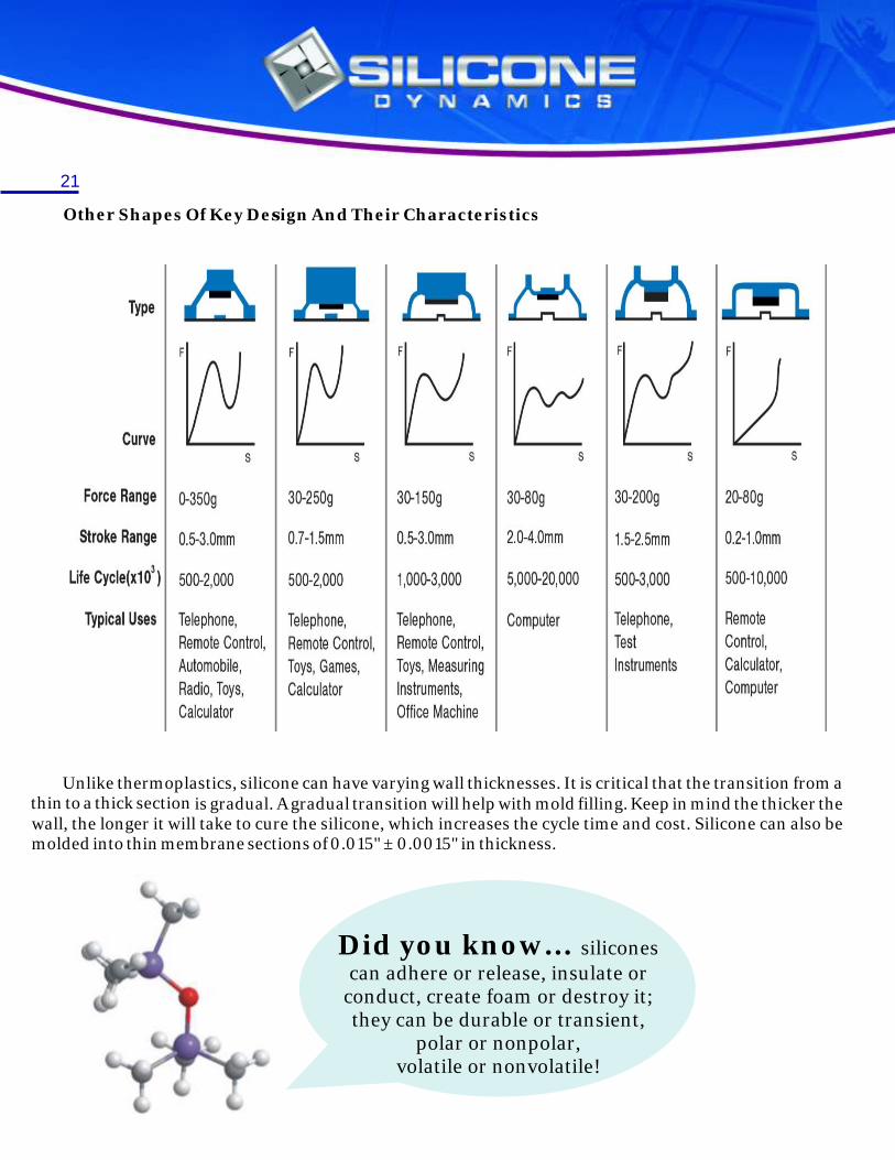
Typical Uses Telephone, Telephone, Telephone, Computer Telephone, Remote Remote Control, Remote Control, Remote Control, Test Control, Automobile, Toys, Games, Toys, Measuring Instruments Calculator, Radio, Toys, Calculator Instruments, Computer Calculator Office Machine
21
Other
is gradual. A gradual transition will help with mold filling. Keep in mind the thicker the wall, the longer it will take to cure the silicone, which increases the cycle time and cost. Silicone can also be molded into thin membrane sections of 0.015" ± 0.0015" in thickness.
Did you know... siliconescan adhere or release, insulate or
conduct, create foam or destroy it;they can be durable or transient,
polar or nonpolar,volatile or nonvolatile!
Shapes Of Key Design And Their Characteristics
Unlike thermoplastics, silicone can have varying wall thicknesses. It is critical that the transition from a thin to a thick section

./ -~ " .:-·- ), ,/"·-.... .-,. ,r·~.., '
:. . •,, ., ....
- -,- . -. - ~ , ;
r. 1 ' r, .. '
':,· ., .. ·;,,.
r ,
i '
' '
. , ;
r ,
22
The membrane shape and size of all rubber switches can be designed so that almost any actuation force and tactile feel can be realized. Most applications require positive tactile feel with relatively long life, so an actuation force of approximately 125 - 150 grams is typically recommended with an accompanying snap ratio of approximately 40 - 60%.
Design Force (grams) Tolerance (+/-)
50 15 g
75 20 g
100 25 g
125 30 g
150 35 g
175 40 g
220-250 50 g
250.1 and up 30 %
Typical tolerance for actuation force is +/- 25 grams. Optimum actuation force for best key performance is 80 - 150 grams. Conductive rubber switches can be successfully designed and manufactured with actuation forces ranging from minimum of 20 grams to a maximum of 500 grams.
Snap Ratio
The snap ratio of a keypad is directly linked to the tactile feel experienced by the user. Designers should attempt to maintain ratios of around 40-60% only dropping below this if they are prepared to compromise tactile to ensure longer life.
Snap ratio is measured as F1-F2 divided by F1, where F1 is the actuation force and F2 is the contact force.
F1 : Actuation Force
F2 : Contact Force
FR : Min Return Force
FD : Drop Force (F1-F2)
S1 : Peak Stroke
S2 : Contact Stroke
Push Curve
Return Curve
DESIGN CONSIDERATIONS

23
Tactile Feedback
The membrane shape and size of any rubber keypad can be designed to achieve almost any combination of actuation force and tactile response. Most applications simply require a positive tactile feel with a long life and as such an actuation force of 125-150grms, with an accompanying snap ratio of 40-60% is a good recommendation.
Variations in tactile response can be achieved with various combinations of contact stroke, actuation force, key shape and material hardness. As a simple rule it should be remembered that the higher the force, the longer the life but the poorer the tactile response. More specific guidelines are difficult to lie down. However, if a customer specifies keypad size, actuation force and stroke, Silicone Dynamics can assist in the membrane design to achieve the required parameters. Always remember to specify higher actuation force for wider or taller keys.
A common problem with rubber keypad design is ensuring that the rocking action that can be a feature of a switch design is minimized. The following suggestions will assist in reducing the problem.
?Keep stroke as near 0.8mm as possible
?Add stabilizing posts on base of key
?Keep web length to a minimum
?Keep web angle as close to 40 o 50
?Actuation force 80-150grms for keys 10-15mm high and 150-175grams for keys 15-25mm high
?Return force should also be set at around 30-35 grams to ensure that keys do not stick.
Example of Design Calculation
If F1 = 150 grams & F2 = 50 grams
150-50 Snap Ratio= ---------- x 100 % = 66.6 %
150
Drop Force = F1-F2 = 100 grams
If F1 = 150 grams & F2 = 100 grams
150-100 Snap Ratio= ---------- x 100 % = 33.3 %
150
Drop Force = F1-F2 = 50 grams

•
i : I ,,l.,, ... ,•\',\ u\·\·, , ,, ' ,,,,._,-, ·-·/ •"'-'"'~ .. ,.'.ll~ ... ,._ --===~ ... =:.:•' ..;,.1,l \ l . . ,! \ ', I I 1 I I , . - '··'''
·' "' · '· l'f(f\ I'.:.
, '. ~ i• •' !.. I i · >
24
Switch Life
Membrane style and the durometer of the material are the factors that most effect switch life. Using a higher durometer silicone, increasing the actuation force or by increasing the stroke will all decrease life.
Minimum Key Height
This can be calculated for any design from:
Keypad base thickness + bezel thickness + stroke of key + 0.5mm
Contacts
Several different types of contacts are available. Depending on required function, select contacts from following types:
1. Screen printing
2. TBSP
3. Carbon Pill
4. Low contact resistance pill
5. Gold plate pill
Five contacts have their own particular characteristics as shown on the graph below.
DESIGN CONSIDERATIONS

Square Ring Semi- Circular Ring
.. ·-: :-::: .. ... r : • (·::::::~::~
.. . :.:::::·:.-: .. ~· I· .· .", ~
l'::::j -:-:i
..,- .. ,f"/'V'T ,·.-.·.·.·.·~ ~ .. ·. ·.· ... · ~ ~ :-:-: . : <·:. ...... ·.·.·.· .... ..... · .. · .. ·.· ... ..... ·.·.·.·.- =.· .·. > :-:-:-1· ~-· ..... ·. ·. . -:-:-:-:-: ··.·:-:-:-:-:·
win • ~ .. •
Rectangular Oval Crrc ular Rong Square
25
Silicone Dynamics offer different types of contact solutions. The carbon pill is most commonly used due to it’s long life (>10 million ops) and low resistance (<100 Ω). The pills are usually circular with diameters ranging from 1.5-10mm and thickness from 0.4-0.6mm.
Printed carbon contacts are available in any shape however thickness is typically 10-20 microns and resistance around 800 Ω. Care must be exercised with electrical design if specifying this type of contact.
Dipped carbon contacts offer a compromise with any shape being available and contact resistance of <300 Ω
Printed Circuit Board Design
Rubber keypads themselves are very reliable in operation but when considering PCB design, the environment that the keypads are to be used in must be taken into consideration to ensure the complete switching unit remains reliable.
The choice of plating for the board is probably the most important factor with the cheaper tin/lead solder boards not being recommended for use with rubber keypads.
Gold plating over nickel is the preferred choice with a recommended layer of 30-50 microns of gold on 100-200 microns of nickel giving contact resistance of <100 Ω.
Nickel plating is the next best option again with good reliability but far more cost effective. A plating level of >200 microns is recommended for best overall performance. This is the most common solution for rubber keypad PCBs.
Silk screen carbon boards should only be used when contact resistances of over 800Ω can be tolerated. Also the minimum track separation should be 0.5mm and the overall pad size should be greater than 5mm.
When designing shorting pads always attempt to get as many shorting paths as possible to increase switch reliability and ensure that the pad size is never smaller than the carbon pill by a minimum of 1.25 times. The most important single objective to be considered in designing any pad pattern is to provide as many shorting paths as possible so best switch operation can be realized when the button is actuated. Several common contact patterns are:

26
Did you know...semiconductors – which are essentialcomponents of virtually all electronic
devices – are made fromhyper-pure silicon andprotected by silicone!

To acf • ueve even 0 2
coat of: k · mm 1s th . ,n on a ' e maxim. concave • fi
recommended um depth d1ff r pro ile . e.ence
'. .,
Printed" ? . ,iraph1c th c· • ~O rmcror (0 02 .ncss E mrr ~
•• ,·,. rurnurn r .. P .nt.no ......... 11·1 ::>.35·nm ""·J·"· D
c enterrnq of tex: (A - B) shall •· ue eq: ·,1 I ~ ... or ,:-: "~ t, " ~ ·, zir v .:mr
,, .stance fro - l rr n ·J 5mrn m e ... gc: of I< •. ob C
Negatr.,ie Fr,": r~ _,
[• ;,
.. , B
·,-:1 .. ~:
' A (
r. ·-····)J ' ··1 .,
' ' . .: j ·- .. - .. ~ ... !
A,
B
27
Silicone rubber keypad manufacturing requires several secondary processes to achieve a complete keypad. To achieve optimum print results and abrasion resistance, minimum radius curvature on top profile of knob shall be as shown:
Printing on Concave surface
Printing on Concave surface
PRINTING

,
,
~ '
--~ --- -----'
------ ---- ------ ' ----\
Product
Bad Printing Corid her'
Silk Screen
' ·",., ---- --· /
I ~ /r I \ \ -_] I I J:>~- -:::S .: ~~~ -':__~::::-L
Pr111ti:1g Process ---
-----
[ ,Q /-- .. l
Avoid drastic difference in key he,gits as this wi r cause diff.cult.es in prirt,ng :
28
Drastic Key height Difference
Laser Etched Keys
Laser etching is the laser controlled process of removing the top coat layer of a painted keypad (usually black in color) to reveal lighter colored layer below (usually white)
The effect is to produce an enhanced backlight effect by only lighting the legends on a keypad. This is the way to create a legend that is vie make with limited to me about that.
By combining laser etching with either EL backlighting or LED backlighting in a range of color options it is possible to produce an interesting range of effects.
Epoxy Key Tops
In order to increase the resiliance of a keypad, a small amount of either gloss or matt epoxy is cured onto the top of each key. This protects the legends and gives the maximum protection from abrasion.
In addition the hard top give the keys a more positive feel and a curved top surface to enhance the design.
Pu Coating
A Pu coating is the minimum protection recommended for the key tops. This is a spray coating, applied after all other processes, which offers a good level of protection for key legends as well as protection from abrasion.

, -'.
",aJ •.
F l:_1:--:.t1·.: ~: "'."" t:·r ~-<u~1r1·;
~-di•··., I~ I ,-·:1.,:1, _
_ ,11•.lu·_·~ J~ Jr F·, .E
Plastic Key Tops
Plastic key tops fit securely on top of a rubber keypad such that the tactile response of a key is increased. Developed for the mobile phone market clients can maintain an existing rubber mat design while upgrading their range of key tops to accommodate a product design change.
This is an ideal solution where a product out off range is evolving quickly and where the ideal tactile response for a product has been established.
Rubber / Mylar Domes
First used in the mobile phone market, the principal of using a mylar layer with snap domes embossed into it, gives a very strong tactile response with a very short key travel.
By varying the shore hardness of the rubber overlay it is possible to accurately tune the response to the user envioriment.
The mylar layer is bonded to the PCB and as such offers a degree of protection from moisture ingress into the switch.
Did you know... mosthypodermic needles, syringes, and
other blood collection equipment usedtoday are coated with silicone.
The silicone does not affect the blood,but it does lubricate the device,making needle insertion easier
and less painful!
29

Actuation Force The force required to collapse the membrane of a rubber switch (identified as Fl on the force/stroke curve).
Air Channel Air path(s) on the bottom of rubber keypads and switches that allows for air passage (venting) when switch is actuated. Switches must be vented on at least two sides.
Alignment Hole Through hole in rubber keypad that is used to position keypad in enclosure when overall keypad size exceeds three inches in either length or width.
Base Silicone sheet material that joins all keys/switches on a rubber keypad. Also known as apron.
Bezel The faceplate or cover, typically either plastic or metal, used to secure a key pad to a printed circuit board. The bezel also aligns the keypad during the final assembly and protects keypad-base material from contact with human hands.
Bosses Small posts used for positive alignment of rubber keypad in bezels or assemblies.
Breakdown Voltage Voltage at which an insulator or dielectric ruptures. Also known as dielectric strength.
Compression Set The measurement of a material’s ability to recover it’s original size and shape after compression under prescribed conditions. It is usually expressed as a recovery percentage (fraction) of the compression condition.
Conductive Rubber Switch Mechanical switch made of silicone rubber, with either direct or indirect contact.
Contact The current-carrying area/surface under each rubber switch (conductive pill or carbon-inked surface) that makes an electrical connection with the electrode on a printed circuit board when the switch is actuated.
Contact Force The force required to maintain rubber-switch contact closure (F2) force/stroke curve with a printed circuit board.
Contact Rating The electric power handling capability for rubber contacts under strictly controlled laboratory conditions.
Draft Angle The amount of taper for molded or cast parts perpendicular to the parting line
Dual Durometer Silicone-rubber keypads manufactured using a two-shot moulding process and two-material hardnesses.
Durometer Durometer is one of several measures of the hardness of a material. Hardness may be defined as a material's resistance to permanent indentation.
TERMINOLOGY 30

Electrode Contact surface/design on a printed circuit board that conducts current when rubber switch is actuated and switch closure occurs.
Key Height The measured distance from the bottom of a keypad (base) to the top surface of a key.
Legend Some type of printed graphic (symbol, letter or number) on the top of the key surface.
Life The number of switch actuations realised before the switch membrane ruptures or over stresses.
Membrane The non-conductive hinge that permits a rubber key to flex, and is responsible for the tactile feel realised.
Negative-Image Graphics Graphics that allow switch colour or switch masking colour to be seen through top-surface printing on keypad.
Overstroke Additional travel experienced with a rubber switch after initial switch closure has been realised. Rubber switches with overstroke require a double-cone or doublebell shaped membrane.
Positive-Image Graphics Single or multi-color printing on top of key surface.
Return Force Force created by switch membrane as it returns the key to a non-actuated position.
Reversed-Out Graphics Graphics that allow rubber color or masking color to be seen through top surface printing on keypad.
Shore A The Durometer Shore A is designed to measure the penetration hardness of rubber, elastomers and other rubber like substances such as neoprene, silicone, and vinyl. It can also be used for soft plastics, felt, leather and similar materials.
Snap Ratio (F1-F2) divided by F1. The difference between the actuation force (F1) and the contact force (F2) of a switch divided by the actuation force.
Stroke Distance from the contact surface on a rubber switch to an electrode pattern on a printed circuit board.
Tactile Feel The response of rubber while depressing. For tactile rubber keypads, it is a critical function of the diaphragm web geometry.
Tear Strength The tear strength is a measure of the resistance of rubber to tear forces. The tear strength is calculated by dividing the maximum force load by the thickness of the rubber.
Wear or abrasion resistance The resistance of a particular ink or coating to manual wearing. The testing process is usually a Norman tester with the number of cycles legends can perform before wear is noticeable.
31

S1 con-. 01 ''ci/11:~S ln., G ':::<0::: Scutl1 r-kf':.a, 97 Suite: r;'. ~·: · E,e11t CR ·~·77'J::' p I 1 (111 '::; .=,. -r ;' 3 . ~ - ,3 ·= .. ~ c F o , ') .; . - 3 . :3 I ::. 7 ~.
Silicone Dynamics, Inc
61535 S. Highway 97
Suite 9-511
Bend, OR 97702