Embed Size (px)
Citation preview
NESR-1600 User's Manual
Telecom / DatacomPURE SINE WAVE INVERTER
NOVA ELECTRIC
Designed for Parallel and Redundant Operation up to 32 kW
Table of Content
1. SAFETY INSTRUCTIONS 1
1-1. General Safety Precautions 1
1-2. Other Safety Notes 2
2. FUNCTIONAL CHARACTERISTICS INTRODUCTION 3
2-1. System 3
2-2. Electrical Specification 4
2-3. Mechanical Drawings 5
2-3-1. NESR-1600 Single Module...................................................... 5
2-3-2. NESR-1600 Rack (19” 2U) ...................................................... 6
2-4. NESR-1600 De-rating Curve 7
2-5. Protection Mechanism 7
3. INSTALLATION AND MAINTENANCE 8
3-1. Introduction 8
3-1-1. LED Indicator ....................................................................... 10
3-1-2. Green Terminal Introduction ................................................ 10
3-1-3. AC Input / Output Terminal .................................................. 13
3-1-4. Parallel Connection Port...................................................... 14
3-1-5. Battery Cabling ....................................................................14
3-1-6. Chassis Ground................................................................... 16
3-1-7. Installation Space Requirement .......................................... 16
3-1-8. RS-485 Port ......................................................................... 16
3-2. Parallel Connection 22
3-2-1. Multi-shelves Installation ...................................................... 22
3-2-2. Parallel Connection with Jumper Setting............................. 22
3-2-3. Parallel Connection with NOVA iC-Hub ............................... 23
3-3. Maintenance 23
3-3-1. Inverter Module Replacement ............................................. 23
3-3-2. Fan Module Replacement ................................................... 25
4. TROUBLE SHOOTING 28
5. WARRANTY 29
1
1. Safety Instructions
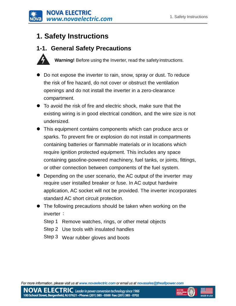
1. Safety Instructions1-1. General Safety Precautions
Warning! Before using the Inverter, read the safety instructions.
Do not expose the inverter to rain, snow, spray or dust. To reduce the risk of fire hazard, do not cover or obstruct the ventilation openings and do not install the inverter in a zero-clearance compartment.To avoid the risk of fire and electric shock, make sure that the existing wiring is in good electrical condition, and the wire size is not undersized.This equipment contains components which can produce arcs or sparks. To prevent fire or explosion do not install in compartments containing batteries or flammable materials or in locations which require ignition protected equipment. This includes any space containing gasoline-powered machinery, fuel tanks, or joints, fittings, or other connection between components of the fuel system.
Depending on the user scenario, the AC output of the inverter mayrequire user installed breaker or fuse. In AC output hardwire application, AC socket will not be provided. The inverter incorporates standard AC short circuit protection.The following precautions should be taken when working on the inverterStep 1Step 2Step 3
Remove watches, rings, or other metal objects Use tools with insulated handles
Wear rubber gloves and boots
NOVA ELECTRICwww.novaelectric.com
2
1. Safety Instructions
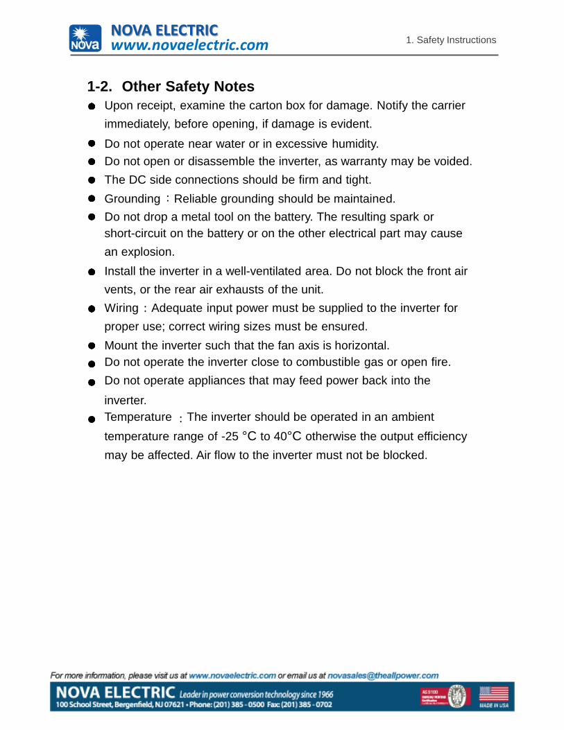
1-2. Other Safety NotesUpon receipt, examine the carton box for damage. Notify the carrier immediately, before opening, if damage is evident.
Do not operate near water or in excessive humidity.Do not open or disassemble the inverter, as warranty may be voided. The DC side connections should be firm and tight.Grounding Reliable grounding should be maintained.Do not drop a metal tool on the battery. The resulting spark orshort-circuit on the battery or on the other electrical part may cause an explosion.Install the inverter in a well-ventilated area. Do not block the front air vents, or the rear air exhausts of the unit.Wiring Adequate input power must be supplied to the inverter for proper use; correct wiring sizes must be ensured.Mount the inverter such that the fan axis is horizontal.Do not operate the inverter close to combustible gas or open fire. Do not operate appliances that may feed power back into the
inverter.Temperature The inverter should be operated in an ambient temperature range of -25 °C to 40°C otherwise the output efficiency may be affected. Air flow to the inverter must not be blocked.
NOVA ELECTRICwww.novaelectric.com
3
2. Functional Characteristics Introduction
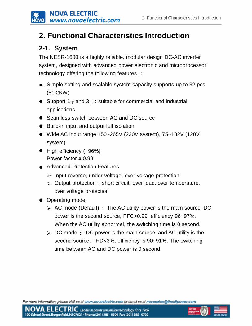
2. Functional Characteristics Introduction2-1. SystemThe NESR-1600 is a highly reliable, modular design DC-AC inverter system, designed with advanced power electronic and microprocessor technology offering the following features
Simple setting and scalable system capacity supports up to 32 pcs (51.2KW)Support 1 and 3 suitable for commercial and industrial applicationsSeamless switch between AC and DC source Build-in input and output full isolationWide AC input range 150~265V (230V system), 75~132V (120V system)High efficiency (~96%)Power factor ≥ 0.99 Advanced Protection Features
Input reverse, under-voltage, over voltage protectionOutput protection short circuit, over load, over temperature, over voltage protection
Operating modeAC mode (Default) The AC utility power is the main source, DC power is the second source, PFC>0.99, efficiency 96~97%.When the AC utility abnormal, the switching time is 0 second. DC mode DC power is the main source, and AC utility is thesecond source, THD<3%, efficiency is 90~91%. The switching time between AC and DC power is 0 second.
NOVA ELECTRICwww.novaelectric.com
2. Functional Characteristics Introduction
4
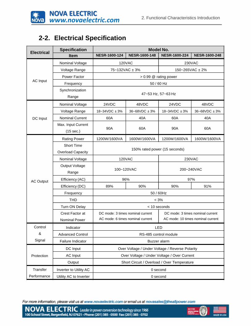
2-2. Electrical Specification
Electrical Specification Model No.Item NESR-1600-124 NESR-1600-148 NESR-1600-224 NESR-1600-248
AC Input
Nominal Voltage 120VAC 230VAC
Voltage Range 75~132VAC ± 3% 150~265VAC ± 2%
Power Factor > 0.99 @ rating power
Frequency 50 / 60 Hz
Synchronization
Range47~53 Hz, 57~63 Hz
DC Input
Nominal Voltage 24VDC 48VDC 24VDC 48VDC
Voltage Range 18~34VDC ± 3% 36~68VDC ± 3% 18~34VDC ± 3% 36~68VDC ± 3%
Nominal Current 60A 40A 60A 40A
Max. Input Current
(15 sec.)90A 60A 90A 60A
AC Output
Rating Power 1200W/1600VA 1600W/1600VA 1200W/1600VA 1600W/1600VA
Short Time
Overload Capacity150% rated power (15 seconds)
Nominal Voltage 120VAC 230VAC
Output Voltage
Range100~120VAC 200~240VAC
Efficiency (AC) 96% 97%
Efficiency (DC) 89% 90% 90% 91%
Frequency 50 / 60Hz
THD < 3%
Turn ON Delay < 10 seconds
Crest Factor at
Nominal Power
DC mode: 3 times nominal current AC mode: 6 times nominal current
DC mode: 3 times nominal current AC mode: 10 times nominal current
Control
&
Signal
Indicator LED
Advanced Control RS-485 control module
Failure Indicator Buzzer alarm
Protection
DC Input Over Voltage / Under Voltage / Reverse Polarity
AC Input Over Voltage / Under Voltage / Over Current
Output Short Circuit / Overload / Over Temperature
Transfer
Performance
Inverter to Utility AC 0 second
Utility AC to Inverter 0 second
NOVA ELECTRICwww.novaelectric.com
2. Functional Characteristics Introduction
5
ElectricalSpecification Model No.
Item NESR-1600-124 NESR-1600-148 NESR-1600-224 NESR-1600-248
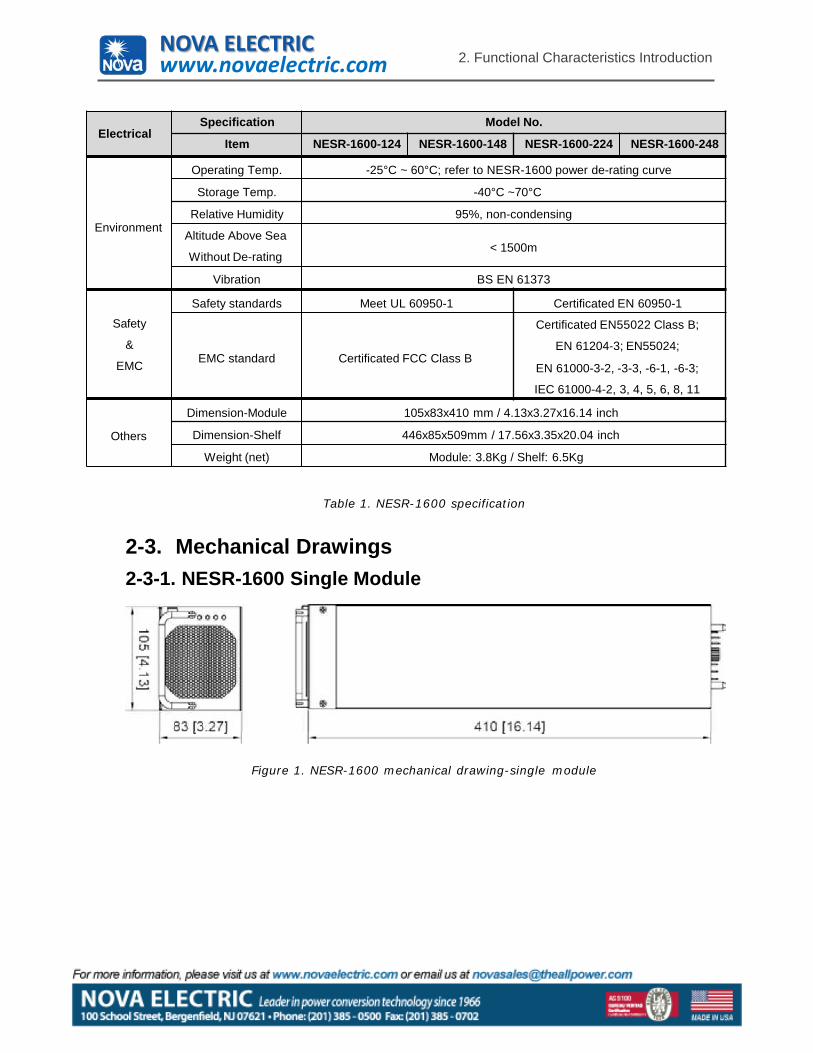
Environment
Operating Temp. -25°C ~ 60°C; refer to NESR-1600 power de-rating curve
Storage Temp. -40°C ~70°C
Relative Humidity 95%, non-condensing
Altitude Above Sea
Without De-rating< 1500m
Vibration BS EN 61373
Safety
&
EMC
Safety standards Meet UL 60950-1 Certificated EN 60950-1
EMC standard Certificated FCC Class B
Certificated EN55022 Class B;
EN 61204-3; EN55024;
EN 61000-3-2, -3-3, -6-1, -6-3;
IEC 61000-4-2, 3, 4, 5, 6, 8, 11
Others
Dimension-Module 105x83x410 mm / 4.13x3.27x16.14 inch
Dimension-Shelf 446x85x509mm / 17.56x3.35x20.04 inch
Weight (net) Module: 3.8Kg / Shelf: 6.5Kg
Table 1. NESR-1600 specification
2-3. Mechanical Drawings2-3-1. NESR-1600 Single Module
Figure 1. NESR-1600 mechanical drawing-single module
NOVA ELECTRICwww.novaelectric.com
2. Functional Characteristics Introduction
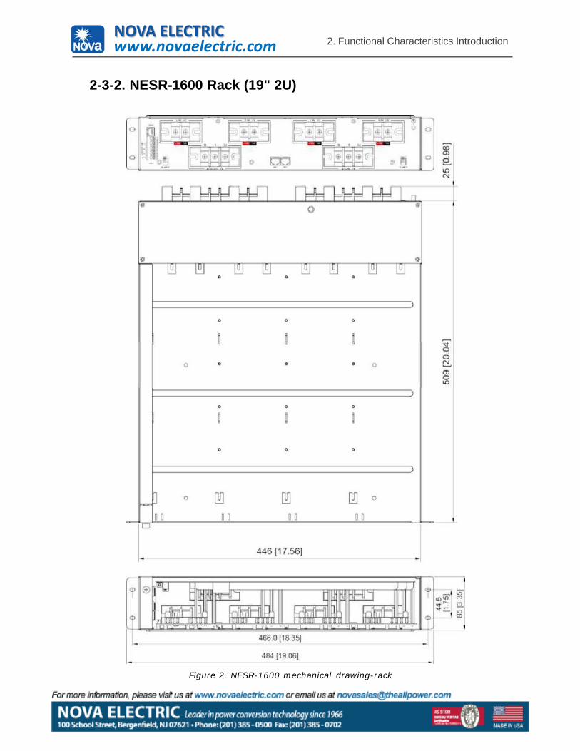
2-3-2. NESR-1600 Rack (19" 2U)
6
Figure 2. NESR-1600 mechanical drawing-rack
NOVA ELECTRICwww.novaelectric.com
2. Functional Characteristics Introduction
7
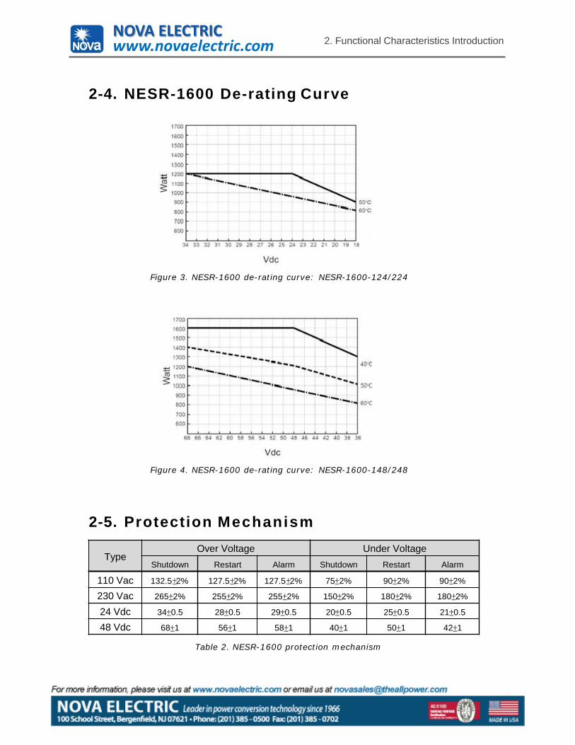
2-4. NESR-1600 De-rating Curve
Figure 3. NESR-1600 de-rating curve: NESR-1600-124/224
Figure 4. NESR-1600 de-rating curve: NESR-1600-148/248
2-5. Protection Mechanism
TypeOver Voltage Under Voltage
Shutdown Restart Alarm Shutdown Restart Alarm
110 Vac 132.5 2% 127.5 2% 127.5 2% 75 2% 90 2% 90 2%
230 Vac 265 2% 255 2% 255 2% 150 2% 180 2% 180 2%
24 Vdc 34 0.5 28 0.5 29 0.5 20 0.5 25 0.5 21 0.5
48 Vdc 68 1 56 1 58 1 40 1 50 1 42 1
Table 2. NESR-1600 protection mechanism
NOVA ELECTRICwww.novaelectric.com
3. Installation and Maintenance
8
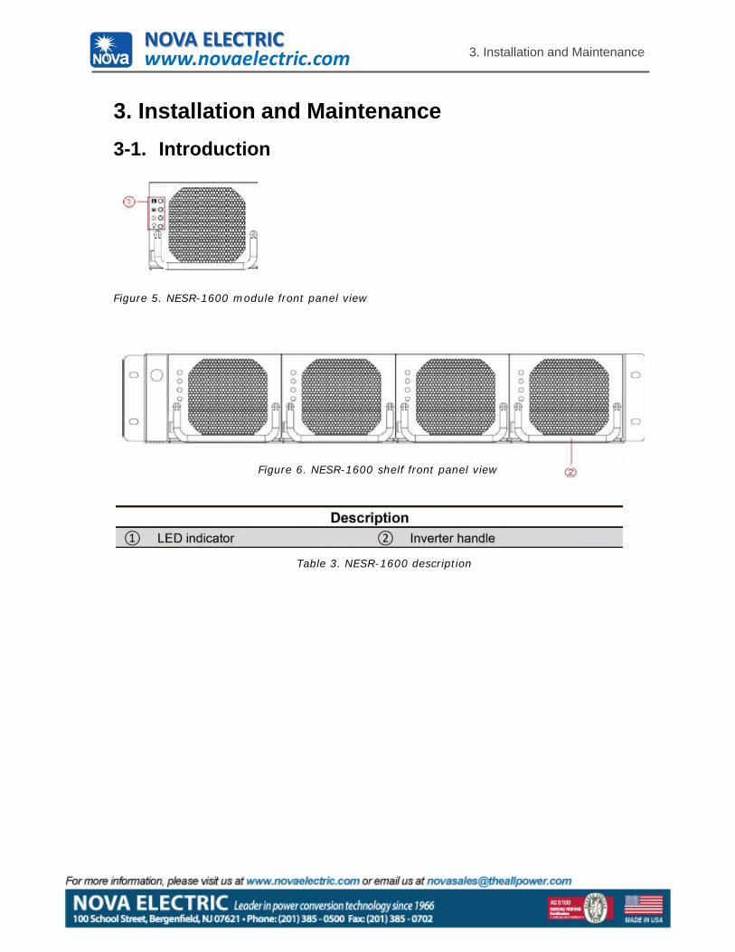
3. Installation and Maintenance3-1. Introduction
Figure 5. NESR-1600 module front panel view
Table 3. NESR-1600 description
Figure 6. NESR-1600 shelf front panel view
NOVA ELECTRICwww.novaelectric.com
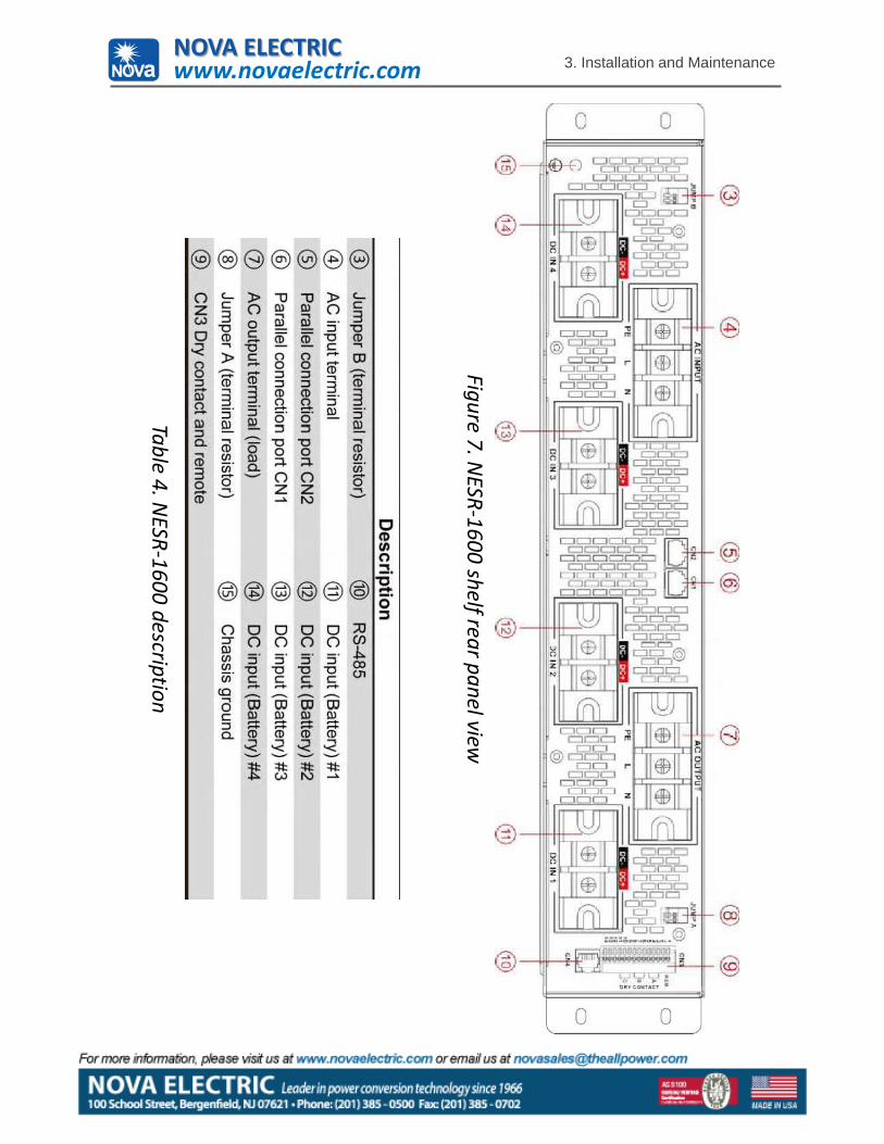
Figure 7. NESR-1600 shelf rear panel view
Table 4. NESR-1600 description
3. Installation and MaintenanceNOVA ELECTRICwww.novaelectric.com
3. Installation and Maintenance
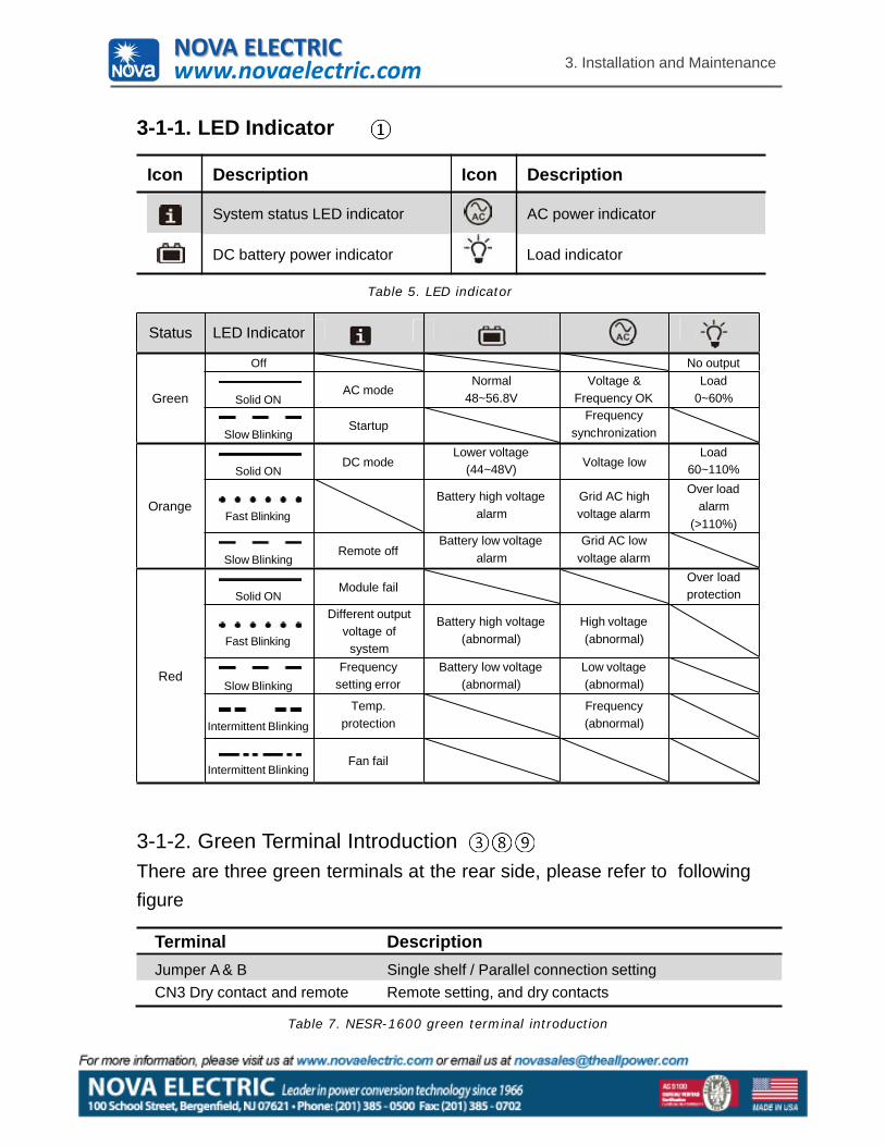
3-1-1. LED Indicator
Icon Description Icon Description
System status LED indicator AC power indicator
DC battery power indicator Load indicator
Table 5. LED indicator
Status
Green
LED Indicator
Off No output
Solid ONAC mode
Normal 48~56.8V
Voltage & Frequency OK
Load 0~60%
Slow BlinkingStartup
Frequency synchronization
Orange
Solid ONDC mode
Lower voltage (44~48V) Voltage low
Load 60~110%
Fast Blinking
Battery high voltage alarm
Grid AC high voltage alarm
Over load alarm
(>110%)
Slow BlinkingRemote off
Battery low voltage alarm
Grid AC low voltage alarm
Red
Solid ONModule fail
Over load protection
Fast Blinking
Different output voltage of
system
Battery high voltage (abnormal)
High voltage (abnormal)
Slow BlinkingFrequency
setting errorBattery low voltage
(abnormal)Low voltage (abnormal)
Intermittent Blinking
Temp. protection
Frequency (abnormal)
Intermittent BlinkingFan fail
3-1-2. Green Terminal IntroductionThere are three green terminals at the rear side, please refer to followingfigure
Terminal DescriptionJumper A & B Single shelf / Parallel connection settingCN3 Dry contact and remote Remote setting, and dry contacts
Table 7. NESR-1600 green terminal introduction
NOVA ELECTRICwww.novaelectric.com
3. Installation and Maintenance
11
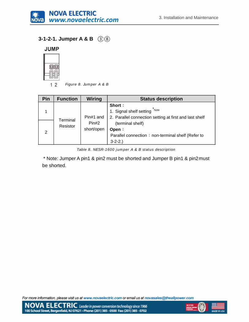
3-1-2-1. Jumper A & B
Figure 8. Jumper A & B
Pin Function Wiring Status description
1
Terminal Resistor
Pin#1 and Pin#2
short/open
Short1. Signal shelf setting *Note
2. Parallel connection setting at first and last shelf (terminal shelf)
OpenParallel connection non-terminal shelf (Refer to 3-2-2.)
2
Table 8. NESR-1600 jumper A & B status description
* Note: Jumper A pin1 & pin2 must be shorted and Jumper B pin1 & pin2must be shorted.
NOVA ELECTRICwww.novaelectric.com
3. Installation and Maintenance
12
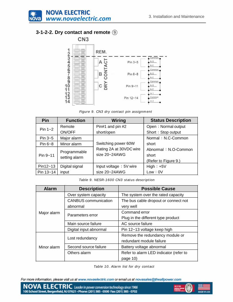
3-1-2-2. Dry contact and remote
Figure 9. CN3 dry contact pin assignment
Pin Function Wiring Status Description
Pin 1~2Remote ON/OFF
Pin#1 and pin #2 short/open
Open Normal output Short Stop output
Pin 3~5 Major alarmSwitching power 60W Rating 2A at 30VDC wire size 20~24AWG
Normal N.C-Common shortAbnormal N.O-Common short(Refer to Figure 9.)
Pin 6~8 Minor alarm
Pin 9~11Programmable setting alarm
Pin12~13 Digital signal input
Input voltage 5V wire size 20~24AWG
High +5VLow 0VPin 13~14
Table 9. NESR-1600 CN3 status description
Alarm Description Possible Cause
Major alarm
Over system capacity The system over the rated capacityCANBUS communication abnormal
The bus cable dropout or connect not very well
Parameters errorCommand errorPlug in the different type product
Main source failure AC source failureDigital input abnormal Pin 12~13 voltage keep high
Minor alarm
Lost redundancyRemove the redundancy module or redundant module failure
Second source failure Battery voltage abnormalOthers alarm Refer to alarm LED indicator (refer to
page 10)
Table 10. Alarm list for dry contact
NOVA ELECTRICwww.novaelectric.com
13
3. Installation and Maintenance
3-1-2-3. Single Shelf Setting1. Please short the Jumper A pin#1 and pin#2.2. Please short the Jumper B pin#1 and pin#2.
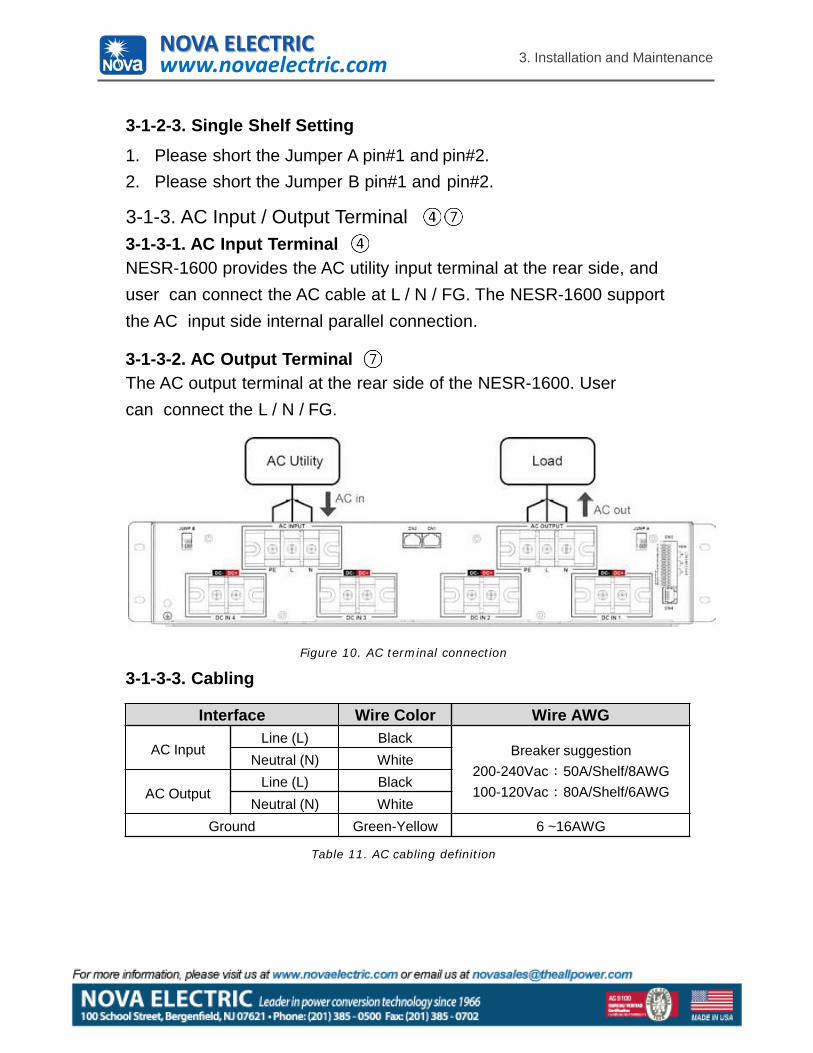
3-1-3. AC Input / Output Terminal3-1-3-1. AC Input TerminalNESR-1600 provides the AC utility input terminal at the rear side, and user can connect the AC cable at L / N / FG. The NESR-1600 support the AC input side internal parallel connection.
3-1-3-2. AC Output TerminalThe AC output terminal at the rear side of the NESR-1600. User can connect the L / N / FG.
Figure 10. AC terminal connection
3-1-3-3. Cabling
Interface Wire Color Wire AWG
AC InputLine (L) Black
Breaker suggestion200-240Vac 50A/Shelf/8AWG100-120Vac 80A/Shelf/6AWG
Neutral (N) White
AC OutputLine (L) Black
Neutral (N) WhiteGround Green-Yellow 6 ~16AWG
Table 11. AC cabling definition
NOVA ELECTRICwww.novaelectric.com
14
3. Installation and Maintenance
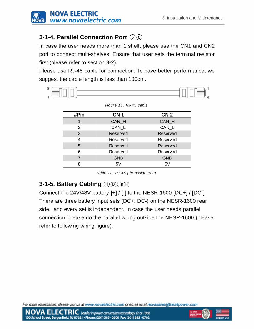
3-1-4. Parallel Connection PortIn case the user needs more than 1 shelf, please use the CN1 and CN2port to connect multi-shelves. Ensure that user sets the terminal resistorfirst (please refer to section 3-2).Please use RJ-45 cable for connection. To have better performance, wesuggest the cable length is less than 100cm.
Figure 11. RJ-45 cable
#Pin CN 1 CN 21 CAN_H CAN_H2 CAN_L CAN_L3 Reserved Reserved4 Reserved Reserved5 Reserved Reserved6 Reserved Reserved7 GND GND8 5V 5V
Table 12. RJ-45 pin assignment
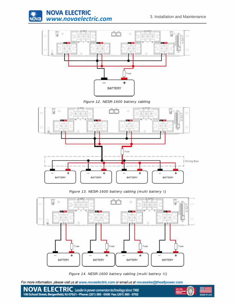
3-1-5. Battery CablingConnect the 24V/48V battery [+] / [-] to the NESR-1600 [DC+] / [DC-] There are three battery input sets (DC+, DC-) on the NESR-1600 rear side, and every set is independent. In case the user needs parallel connection, please do the parallel wiring outside the NESR-1600 (please refer to following wiring figure).
NOVA ELECTRICwww.novaelectric.com
3. Installation and Maintenance
Figure 12. NESR-1600 battery cabling
Figure 13. NESR-1600 battery cabling (multi battery I)
Figure 14. NESR-1600 battery cabling (multi battery II)
NOVA ELECTRICwww.novaelectric.com
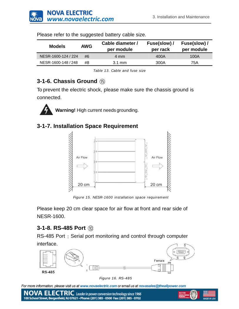
Figure 16. RS-485
per module per rack per moduleNESR-1600-124 / 224 #6 4 mm 400A 100ANESR-1600-148 / 248 #8 3.1 mm 300A 75A
Table 13. Cable and fuse size
16
3. Installation and Maintenance
Please refer to the suggested battery cable size.
Models AWG Cable diameter / Fuse(slow) / Fuse(slow) /
3-1-6. Chassis GroundTo prevent the electric shock, please make sure the chassis ground is connected.
Warning! High current needs grounding.
3-1-7. Installation Space Requirement
Figure 15. NESR-1600 installation space requirement
Please keep 20 cm clear space for air flow at front and rear side of NESR-1600.
3-1-8. RS-485 PortRS-485 Port Serial port monitoring and control through computer interface.
NOVA ELECTRICwww.novaelectric.com
3. Installation and Maintenance
17
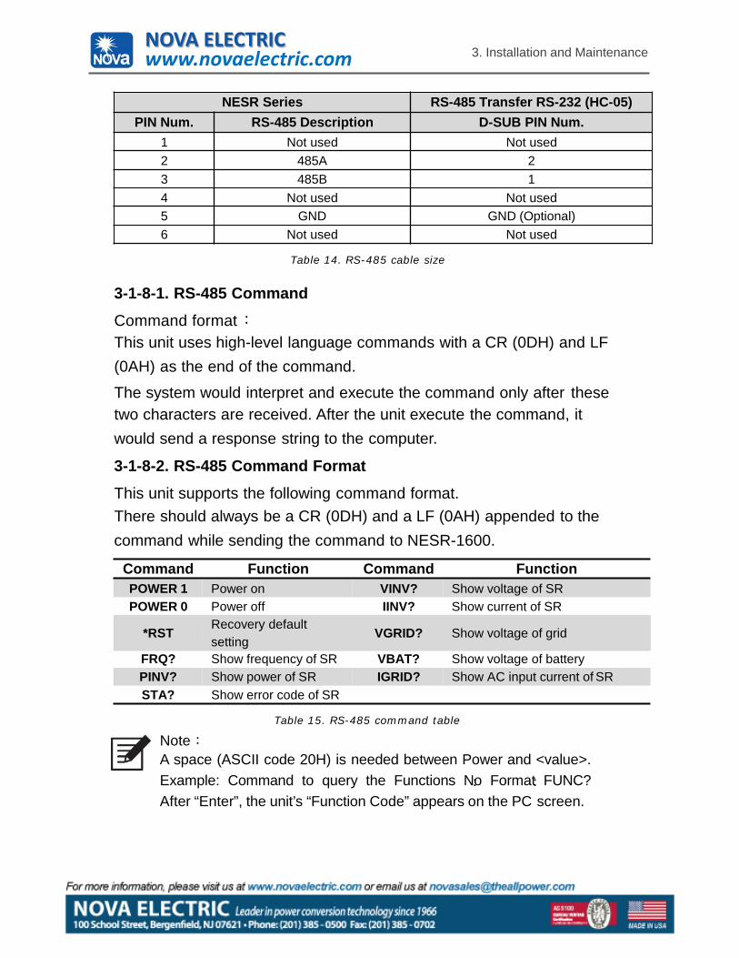
NESR Series RS-485 Transfer RS-232 (HC-05)PIN Num. RS-485 Description D-SUB PIN Num.
1 Not used Not used2 485A 23 485B 14 Not used Not used5 GND GND (Optional)6 Not used Not used
Table 14. RS-485 cable size
3-1-8-1. RS-485 CommandCommand formatThis unit uses high-level language commands with a CR (0DH) and LF (0AH) as the end of the command.
The system would interpret and execute the command only after thesetwo characters are received. After the unit execute the command, it would send a response string to the computer.
3-1-8-2. RS-485 Command FormatThis unit supports the following command format.There should always be a CR (0DH) and a LF (0AH) appended to the command while sending the command to NESR-1600.
Command Function Command FunctionPOWER 1 Power on VINV? Show voltage of SRPOWER 0 Power off IINV? Show current of SR
*RST Recovery defaultsetting
VGRID? Show voltage of grid
FRQ? Show frequency of SR VBAT? Show voltage of batteryPINV? Show power of SR IGRID? Show AC input current of SRSTA? Show error code of SR
Table 15. RS-485 command table
NoteA space (ASCII code 20H) is needed between Power and <value>.Example: Command to query the Functions No Format FUNC?After “Enter”, the unit’s “Function Code” appears on the PC screen.
NOVA ELECTRICwww.novaelectric.com
18
3. Installation and Maintenance
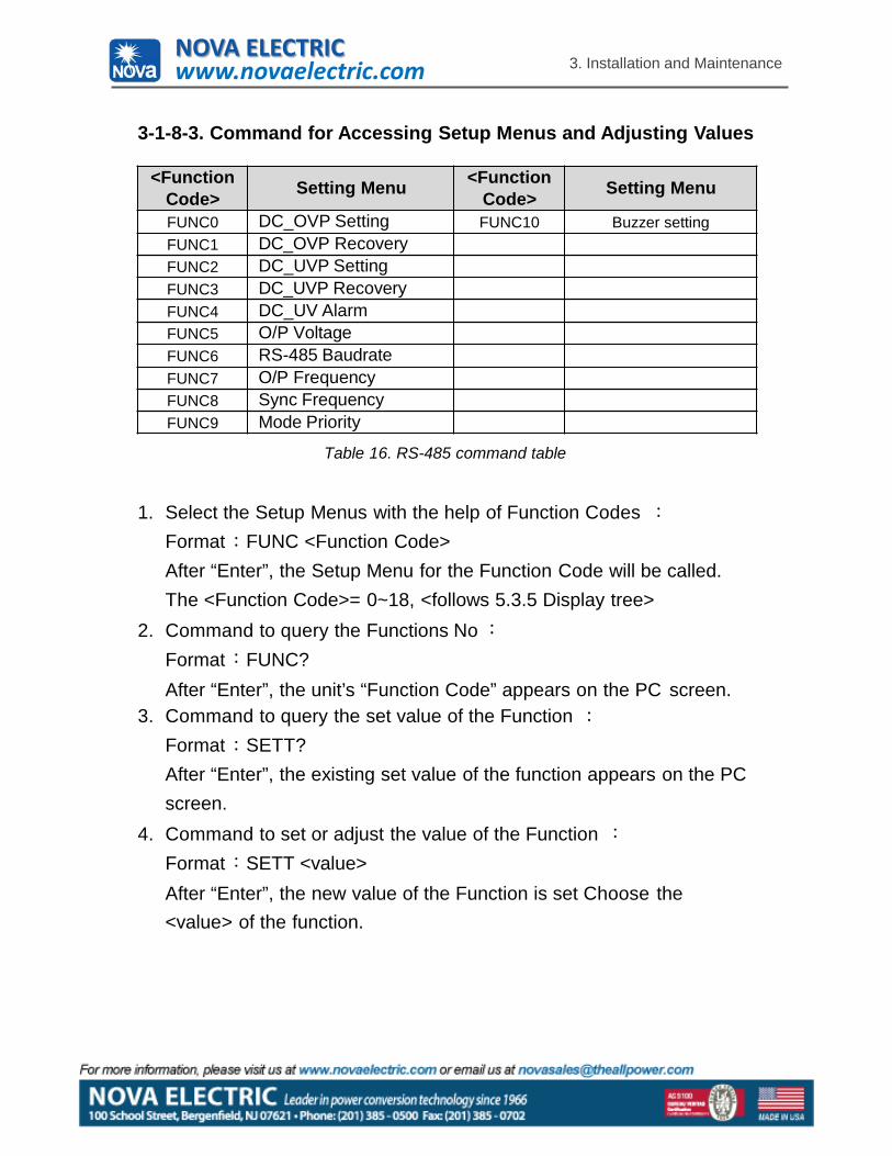
3-1-8-3. Command for Accessing Setup Menus and Adjusting Values
<Function Code> Setting Menu <Function
Code> Setting Menu
FUNC0 DC_OVP Setting FUNC10 Buzzer settingFUNC1 DC_OVP RecoveryFUNC2 DC_UVP SettingFUNC3 DC_UVP RecoveryFUNC4 DC_UV AlarmFUNC5 O/P VoltageFUNC6 RS-485 BaudrateFUNC7 O/P FrequencyFUNC8 Sync FrequencyFUNC9 Mode Priority
1. Select the Setup Menus with the help of Function Codes Format FUNC <Function Code>After “Enter”, the Setup Menu for the Function Code will be called. The <Function Code>= 0~18, <follows 5.3.5 Display tree>
2. Command to query the Functions No Format FUNC?After “Enter”, the unit’s “Function Code” appears on the PC screen.
3. Command to query the set value of the Function Format SETT?After “Enter”, the existing set value of the function appears on the PC screen.
4. Command to set or adjust the value of the Function Format SETT <value>After “Enter”, the new value of the Function is set Choose the<value> of the function.
Table 16. RS-485 command table
NOVA ELECTRICwww.novaelectric.com
3. Installation and Maintenance
19
Set the Over Voltage Protection (OVP) and
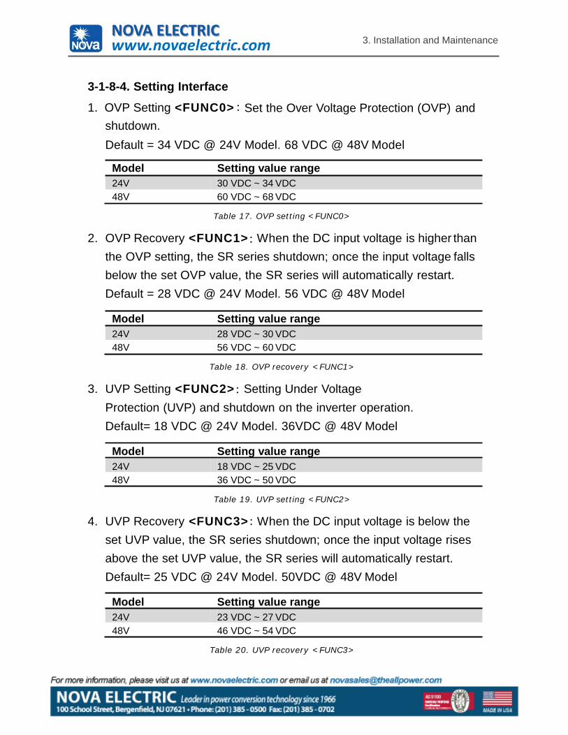
3-1-8-4. Setting Interface
1. OVP Setting <FUNC0>shutdown.Default = 34 VDC @ 24V Model. 68 VDC @ 48V Model
Model Setting value range24V 30 VDC ~ 34 VDC48V 60 VDC ~ 68 VDC
Table 17. OVP setting <FUNC0>
2. OVP Recovery <FUNC1> When the DC input voltage is higher than the OVP setting, the SR series shutdown; once the input voltage falls below the set OVP value, the SR series will automatically restart. Default = 28 VDC @ 24V Model. 56 VDC @ 48V Model
Model Setting value range24V 28 VDC ~ 30 VDC48V 56 VDC ~ 60 VDC
Table 18. OVP recovery <FUNC1>
3. UVP Setting <FUNC2> Setting Under Voltage Protection (UVP) and shutdown on the inverter operation. Default= 18 VDC @ 24V Model. 36VDC @ 48V Model
Model Setting value range24V 18 VDC ~ 25 VDC48V 36 VDC ~ 50 VDC
Table 19. UVP setting <FUNC2>
4. UVP Recovery <FUNC3> When the DC input voltage is below the set UVP value, the SR series shutdown; once the input voltage rises above the set UVP value, the SR series will automatically restart. Default= 25 VDC @ 24V Model. 50VDC @ 48V Model
Model Setting value range24V 23 VDC ~ 27 VDC48V 46 VDC ~ 54 VDC
Table 20. UVP recovery <FUNC3>
NOVA ELECTRICwww.novaelectric.com
3. Installation and Maintenance
20
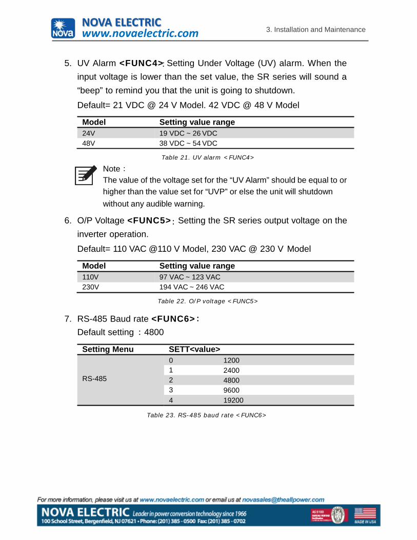
5. UV Alarm <FUNC4> Setting Under Voltage (UV) alarm. When theinput voltage is lower than the set value, the SR series will sound a“beep” to remind you that the unit is going to shutdown.
Default= 21 VDC @ 24 V Model. 42 VDC @ 48 V Model
Model Setting value range24V 19 VDC ~ 26 VDC48V 38 VDC ~ 54 VDC
Table 21. UV alarm <FUNC4>
NoteThe value of the voltage set for the “UV Alarm” should be equal to or higher than the value set for “UVP” or else the unit will shutdownwithout any audible warning.
6. O/P Voltage <FUNC5> Setting the SR series output voltage on the inverter operation.
Default= 110 VAC @110 V Model, 230 VAC @ 230 V Model
Model Setting value range110V 97 VAC ~ 123 VAC230V 194 VAC ~ 246 VAC
Table 22. O/P voltage <FUNC5>
7. RS-485 Baud rate <FUNC6>Default setting 4800
Setting Menu SETT<value>
RS-485
0 12001 24002 48003 96004 19200
Table 23. RS-485 baud rate <FUNC6>
NOVA ELECTRICwww.novaelectric.com
3. Installation and Maintenance
21
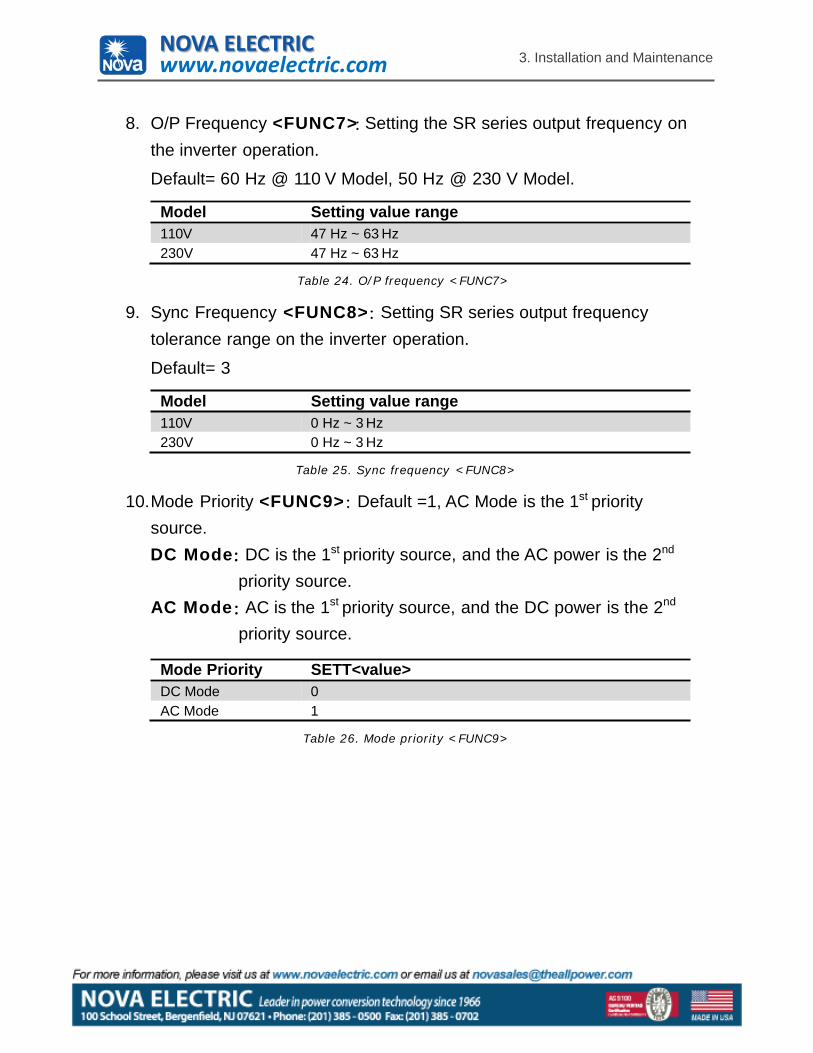
8. O/P Frequency <FUNC7> Setting the SR series output frequency on the inverter operation.
Default= 60 Hz @ 110 V Model, 50 Hz @ 230 V Model.
Model Setting value range110V 47 Hz ~ 63 Hz230V 47 Hz ~ 63 Hz
Table 24. O/P frequency <FUNC7>
9. Sync Frequency <FUNC8> Setting SR series output frequency tolerance range on the inverter operation.
Default= 3
Model Setting value range110V 0 Hz ~ 3 Hz230V 0 Hz ~ 3 Hz
Table 25. Sync frequency <FUNC8>
10.Mode Priority <FUNC9> Default =1, AC Mode is the 1st priority source.DC Mode DC is the 1st priority source, and the AC power is the 2nd
priority source.AC Mode AC is the 1st priority source, and the DC power is the 2nd
priority source.
Mode Priority SETT<value>DC Mode 0AC Mode 1
Table 26. Mode priority <FUNC9>
NOVA ELECTRICwww.novaelectric.com
3. Installation and Maintenance
22
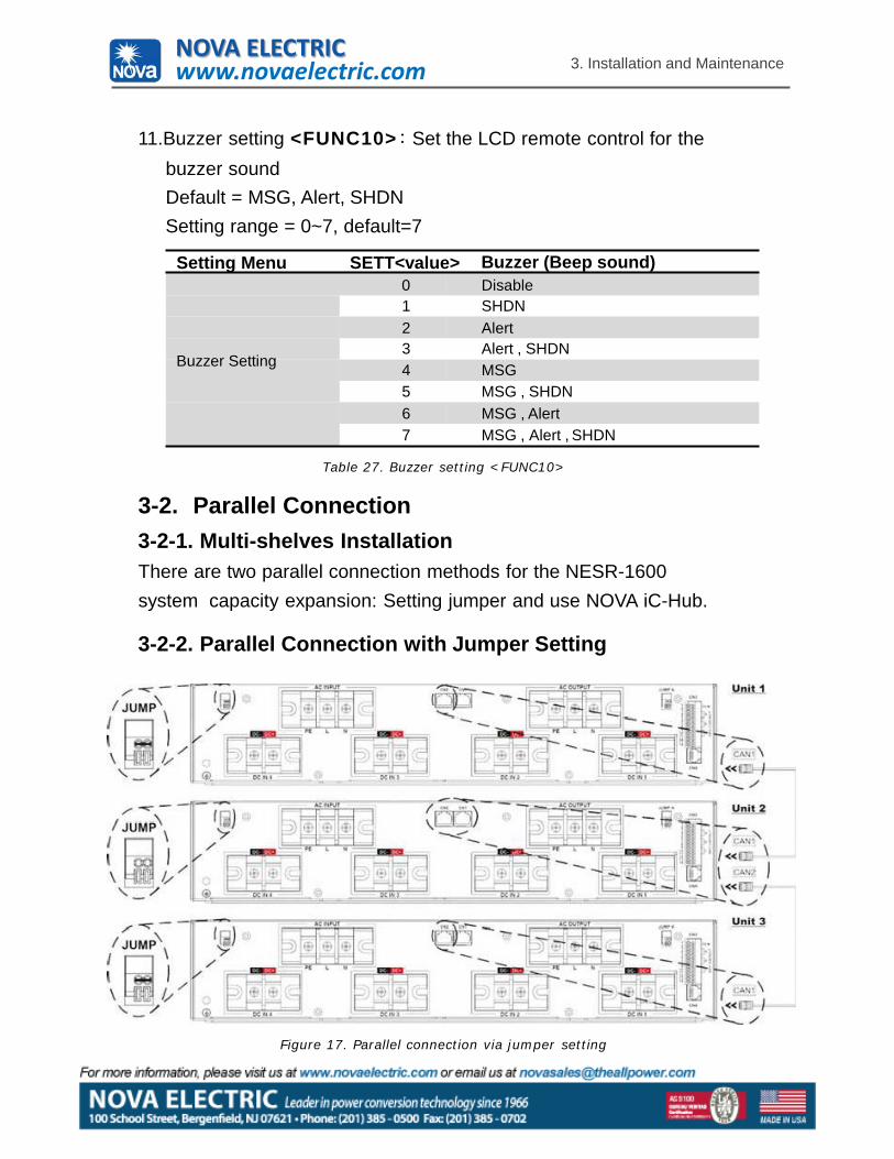
Set the LCD remote control for the11.Buzzer setting <FUNC10>buzzer soundDefault = MSG, Alert, SHDNSetting range = 0~7, default=7
Setting Menu SETT<value> Buzzer (Beep sound)0 Disable1 SHDN2 Alert3 Alert , SHDN
Buzzer Setting 4 MSG5 MSG , SHDN6 MSG , Alert7 MSG , Alert , SHDN
Table 27. Buzzer setting <FUNC10>
3-2. Parallel Connection3-2-1. Multi-shelves InstallationThere are two parallel connection methods for the NESR-1600system capacity expansion: Setting jumper and use NOVA iC-Hub.
3-2-2. Parallel Connection with Jumper Setting
Figure 17. Parallel connection via jumper setting
NOVA ELECTRICwww.novaelectric.com
3. Installation and Maintenance
Green terminal JUMP connection
Parallel connect Unit 1 Unit 2 Unit 3JUMP Connected Not connected Connected
Take 3 units for example, only the first and the last unit need to connect jumper.
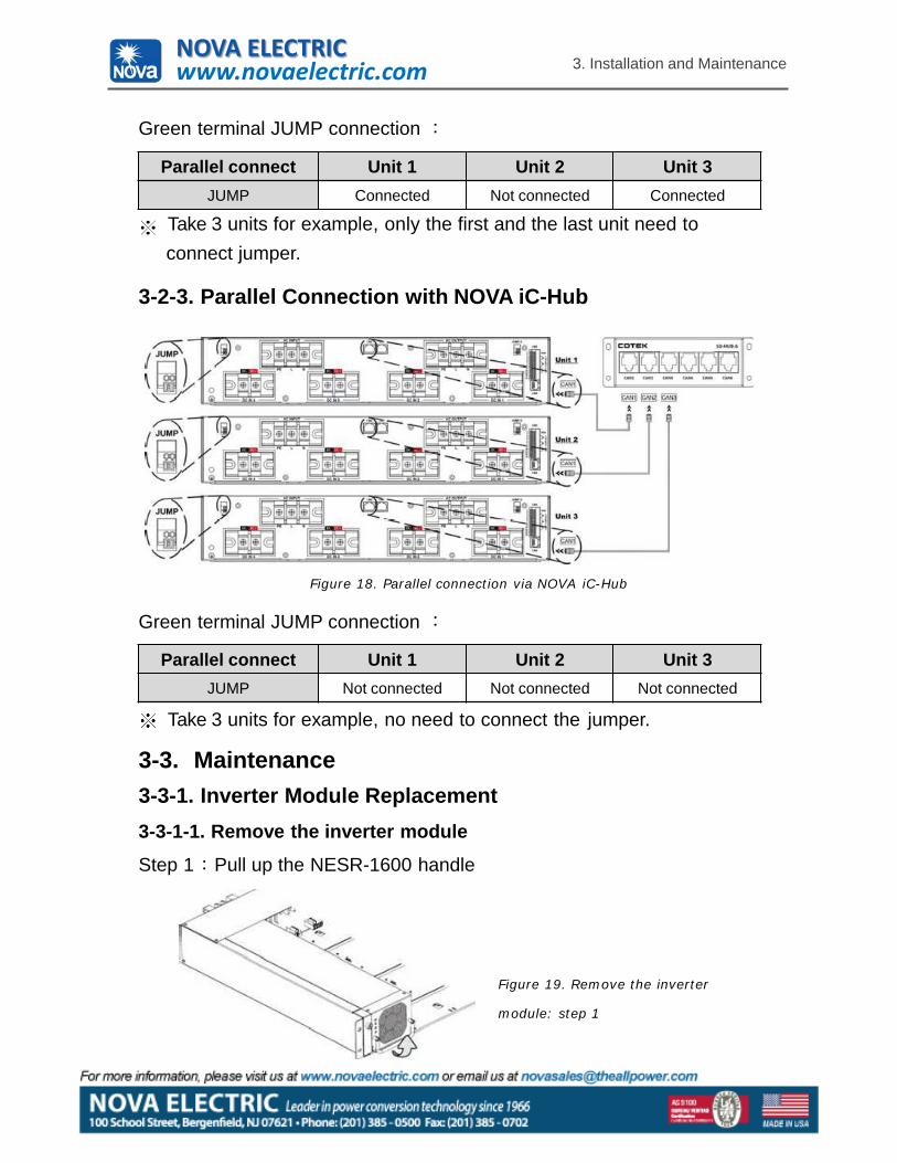
3-2-3. Parallel Connection with NOVA iC-Hub
Figure 18. Parallel connection via NOVA iC-Hub
Green terminal JUMP connection
Parallel connect Unit 1 Unit 2 Unit 3JUMP Not connected Not connected Not connected
Take 3 units for example, no need to connect the jumper.
3-3. Maintenance3-3-1. Inverter Module Replacement3-3-1-1. Remove the inverter module
Step 1 Pull up the NESR-1600 handle
Figure 19. Remove the inverter
module: step 1
NOVA ELECTRICwww.novaelectric.com
3. Installation and Maintenance
24
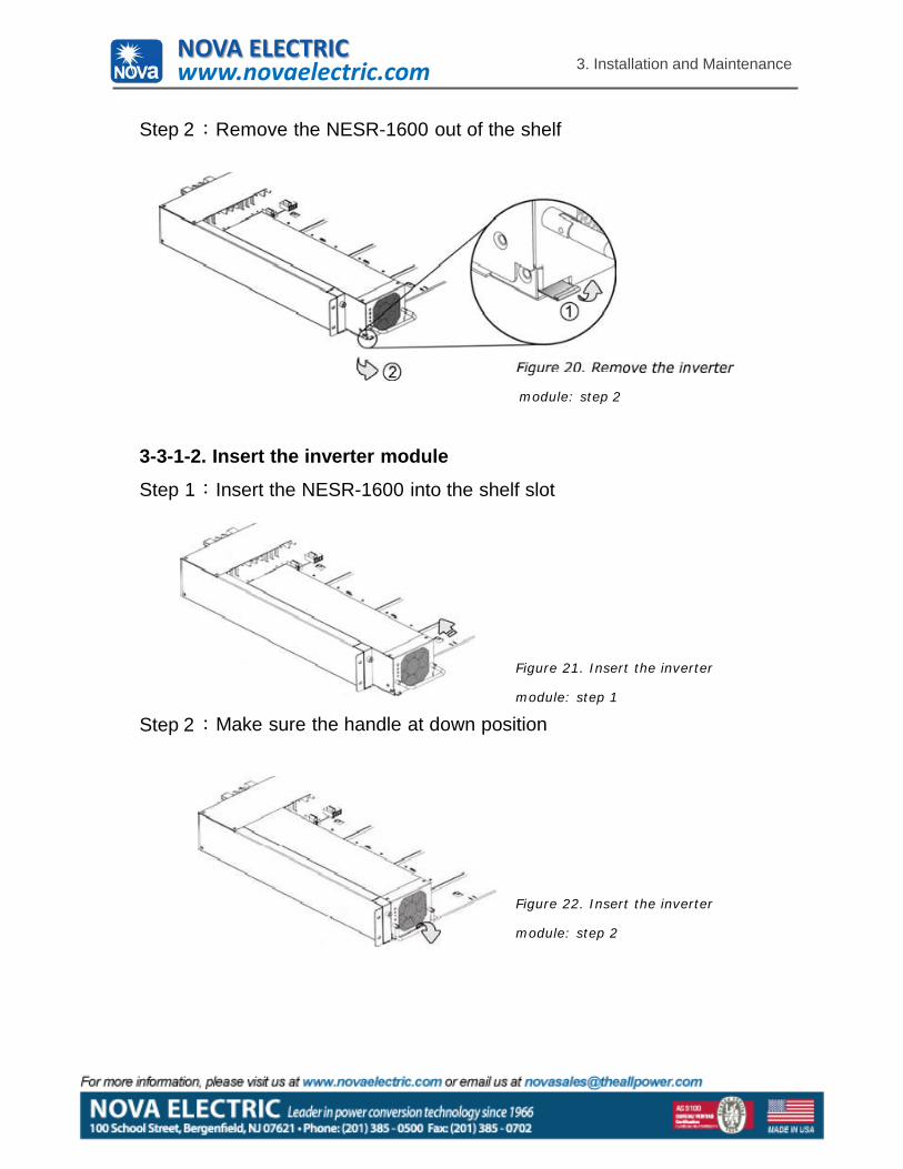
Step 2 Remove the NESR-1600 out of the shelf
module: step 2
3-3-1-2. Insert the inverter module
Step 1 Insert the NESR-1600 into the shelf slot
Step 2
Figure 21. Insert the inverter
module: step 1
Make sure the handle at down position
Figure 22. Insert the inverter
module: step 2
NOVA ELECTRICwww.novaelectric.com
3. Installation and Maintenance
25
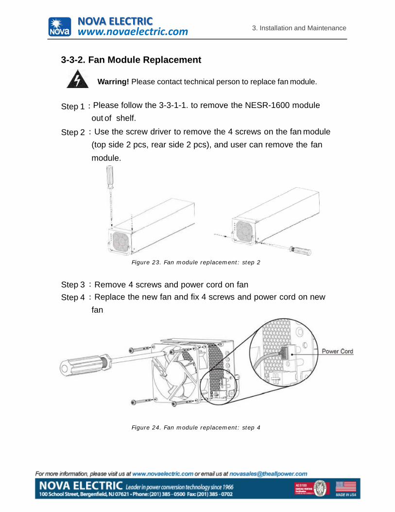
3-3-2. Fan Module Replacement
Warring! Please contact technical person to replace fan module.
Step 1
Step 2
Please follow the 3-3-1-1. to remove the NESR-1600 module out of shelf.Use the screw driver to remove the 4 screws on the fan module
(top side 2 pcs, rear side 2 pcs), and user can remove the fanmodule.
Figure 23. Fan module replacement: step 2
Step 3Step 4
Remove 4 screws and power cord on fanReplace the new fan and fix 4 screws and power cord on new
fan
Figure 24. Fan module replacement: step 4
NOVA ELECTRICwww.novaelectric.com
3. Installation and Maintenance
26
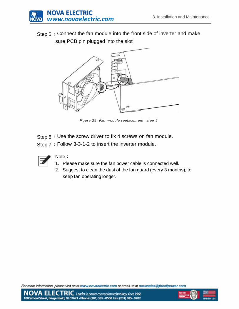
Step 5 Connect the fan module into the front side of inverter and make sure PCB pin plugged into the slot
Figure 25. Fan module replacement: step 5
Step 6Step 7
Use the screw driver to fix 4 screws on fan module. Follow 3-3-1-2 to insert the inverter module.
Note1. Please make sure the fan power cable is connected well.2. Suggest to clean the dust of the fan guard (every 3 months), to
keep fan operating longer.
NOVA ELECTRICwww.novaelectric.com
27
3. Installation and Maintenance
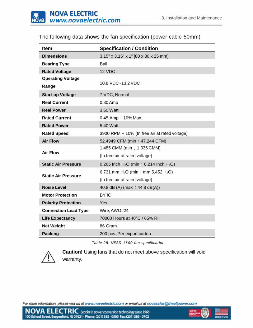
The following data shows the fan specification (power cable 50mm)
Item Specification / ConditionDimensions 3.15” x 3.15” x 1” [80 x 80 x 25 mm]
Bearing Type Ball
Rated Voltage 12 VDCOperating Voltage
Range 10.8 VDC~13.2 VDC
Start-up Voltage 7 VDC, Normal
Real Current 0.30 Amp
Real Power 3.60 Watt
Rated Current 0.45 Amp + 10% Max.
Rated Power 5.40 Watt
Rated Speed 3900 RPM + 10% (In free air at rated voltage)
Air Flow 52.4949 CFM (min 47.244 CFM)
Air Flow1.485 CMM (min 1.336 CMM)
(In free air at rated voltage)
Static Air Pressure 0.265 Inch H2O (min 0.214 Inch H2O)
Static Air Pressure6.731 mm H2O (min mm 5.452 H2O)
(In free air at rated voltage)
Noise Level 40.8 dB (A) (max 44.8 dB(A))
Motor Protection BY IC
Polarity Protection Yes
Connection Lead Type Wire, AWG#24
Life Expectancy 70000 Hours at 40°C / 65% RH
Net Weight 86 Gram.
Packing 200 pcs. Per export carton
Table 28. NESR-1600 fan specification
Caution! Using fans that do not meet above specification will void warranty.
NOVA ELECTRICwww.novaelectric.com
4. Trouble Shooting
28
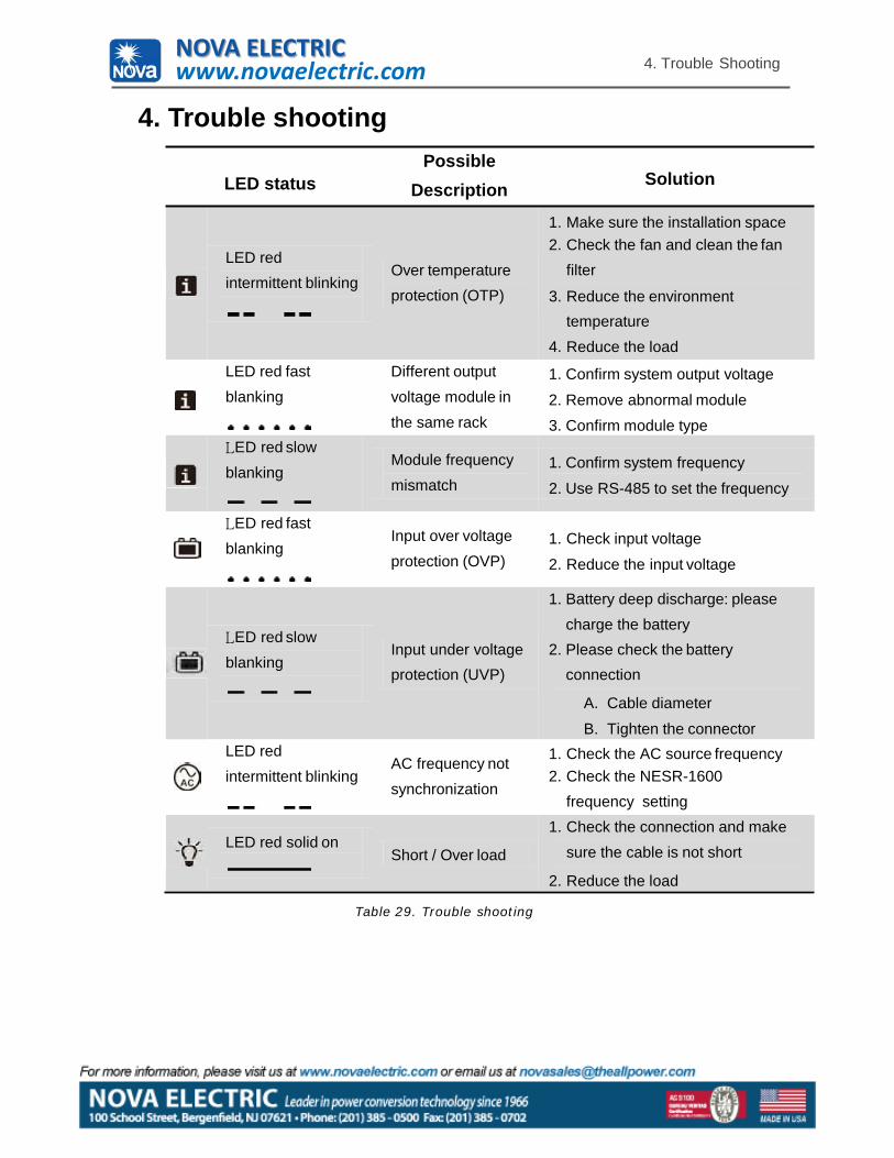
4. Trouble shooting
LED statusPossible
Description Solution
LED red intermittent blinking
Over temperature protection (OTP)
1. Make sure the installation space2. Check the fan and clean the fan
filter
3. Reduce the environment temperature
4. Reduce the loadLED red fast blanking
Different output voltage module in the same rack
1. Confirm system output voltage
2. Remove abnormal module3. Confirm module type
LED red slow blanking
Module frequency mismatch
1. Confirm system frequency
2. Use RS-485 to set the frequency
LED red fast blanking
Input over voltage protection (OVP)
1. Check input voltage
2. Reduce the input voltage
LED red slow blanking
1. Battery deep discharge: please charge the battery
Input under voltage 2. Please check the battery protection (UVP) connection
A. Cable diameter
B. Tighten the connectorLED red intermittent blinking
AC frequency not synchronization
1. Check the AC source frequency2. Check the NESR-1600
frequency setting
LED red solid onShort / Over load
1. Check the connection and make sure the cable is not short
2. Reduce the load
Table 29. Trouble shooting
NOVA ELECTRICwww.novaelectric.com
29
5. Warranty
5. WarrantyWarning! Do not open or disassemble the Inverter. Attempting to doso may cause risk of electrical shock or fire.
We guarantee this product against defects in materials and workmanship for a period of 24 months from the date of purchase. In case you need to repair or replace any defective power inverters, please contact NOVA local distributor.This warranty will be considered void if the unit has been misused, altered, or accidentally damaged. NOVA is not liable for anything that occurs as a result of the user’s fault.
NOVA ELECTRICwww.novaelectric.com

100 School Street, Bergenfield, NJ
Phone: 201 385 0500 FAX: 201 385 0702
www.novaelectric.com