Embed Size (px)
Citation preview
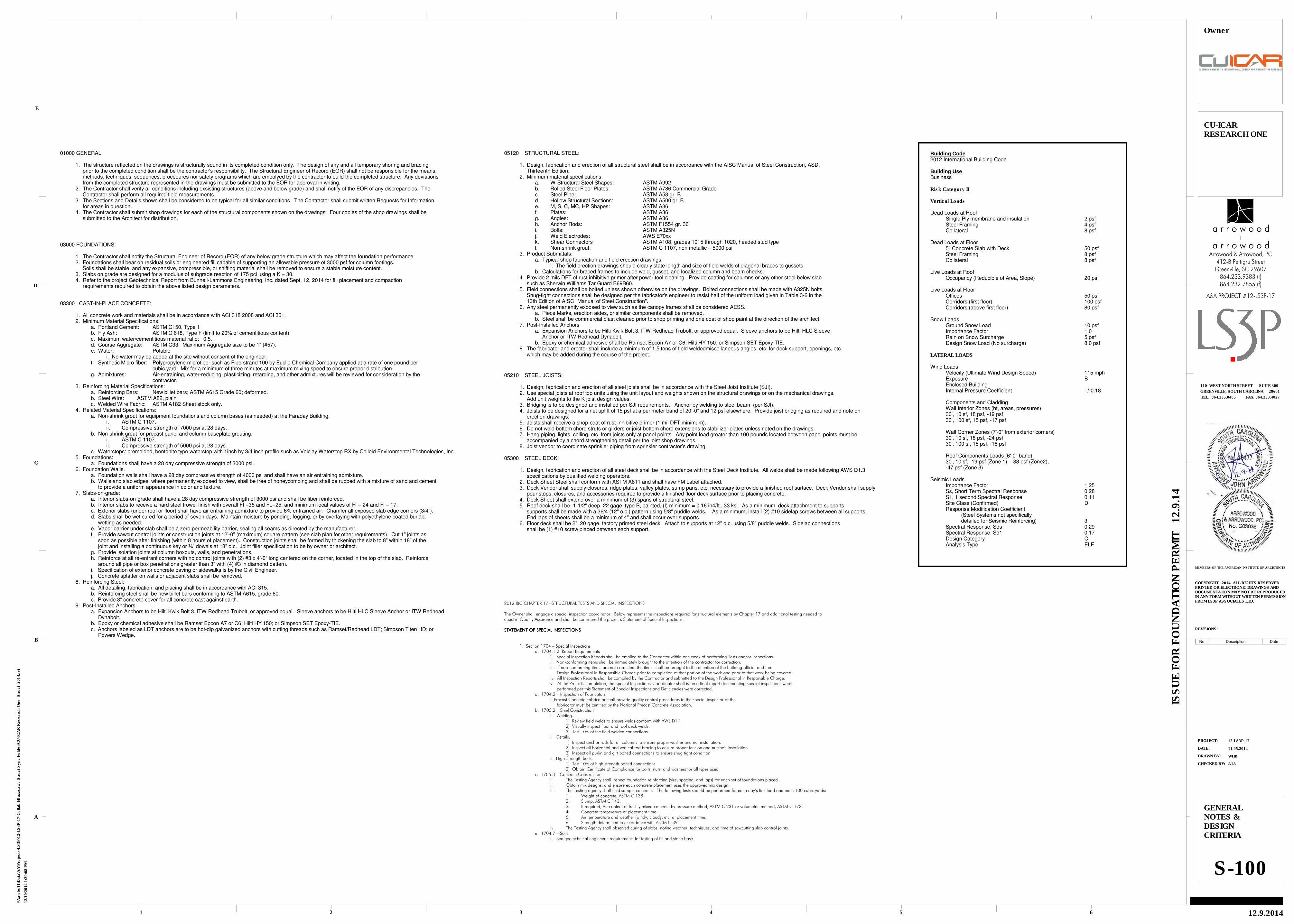
Building Code2012 International Building Code
Building UseBusiness
Risk Category II
Vertical Loads
Dead Loads at RoofSingle Ply membrane and insulation 2 psfSteel Framing 4 psfCollateral 8 psf
Dead Loads at Floor5" Concrete Slab with Deck 50 psfSteel Framing 8 psfCollateral 8 psf
Live Loads at RoofOccupancy (Reducible of Area, Slope) 20 psf
Live Loads at FloorOffices 50 psfCorridors (first floor) 100 psfCorridors (above first floor) 80 psf
Snow LoadsGround Snow Load 10 psfImportance Factor 1.0Rain on Snow Surcharge 5 psfDesign Snow Load (No surcharge) 8.0 psf
LATERAL LOADS
Wind LoadsVelocity (Ultimate Wind Design Speed) 115 mphExposure BEnclosed BuildingInternal Pressure Coefficient +/-0.18
Components and CladdingWall Interior Zones (ht, areas, pressures)30', 10 sf, 18 psf, -19 psf30', 100 sf, 15 psf, -17 psf
Wall Corner Zones (7'-0" from exterior corners)30', 10 sf, 18 psf, -24 psf30', 100 sf, 15 psf, -18 psf
Roof Components Loads (6'-0" band)30', 10 sf, -19 psf (Zone 1), - 33 psf (Zone2),-47 psf (Zone 3)
Seismic LoadsImportance Factor 1.25Ss, Short Term Spectral Response 0.28S1, 1 second Spectral Response 0.11Site Class (Confirmed) DResponse Modification Coefficient
(Steel Systems not specificallydetailed for Seismic Reinforcing) 3
Spectral Response, Sds 0.29Spectral Response, Sd1 0.17Design Category CAnalysis Type ELF
03000 FOUNDATIONS:
1. The Contractor shall notify the Structural Engineer of Record (EOR) of any below grade structure which may affect the foundation performance.2. Foundations shall bear on residual soils or engineered fill capable of supporting an allowable pressure of 3000 psf for column footings.
Soils shall be stable, and any expansive, compressible, or shifting material shall be removed to ensure a stable moisture content.3. Slabs on grade are designed for a modulus of subgrade reaction of 175 pci using a K = 30.4. Refer to the project Geotechnical Report from Bunnell-Lammons Engineering, Inc. dated Sept. 12, 2014 for fill placement and compaction requirements required to obtain the above listed design parameters.
03300 CAST-IN-PLACE CONCRETE:
1. All concrete work and materials shall be in accordance with ACI 318 2008 and ACI 301.2. Minimum Material Specifications:
a. Portland Cement: ASTM C150, Type 1b. Fly Ash: ASTM C 618, Type F (limit to 20% of cementitious content)c. Maximum water/cementitious material ratio: 0.5.d. Course Aggregate: ASTM C33. Maximum Aggregate size to be 1" (#57).e. Water: Potable
i. No water may be added at the site without consent of the engineer.f. Synthetic Micro fiber: Polypropylene microfiber such as Fiberstrand 100 by Euclid Chemical Company applied at a rate of one pound per cubic yard. Mix for a minimum of three minutes at maximum mixing speed to ensure proper distribution.g. Admixtures: Air-entraining, water-reducing, plasticizing, retarding, and other admixtures will be reviewed for consideration by the
contractor.3. Reinforcing Material Specifications:
a. Reinforcing Bars: New billet bars; ASTM A615 Grade 60; deformed.b. Steel Wire: ASTM A82, plainc. Welded Wire Fabric: ASTM A182 Sheet stock only.
4. Related Material Specifications:a. Non-shrink grout for equipment foundations and column bases (as needed) at the Faraday Building.
i. ASTM C 1107.ii. Compressive strength of 7000 psi at 28 days.
b. Non-shrink grout for precast panel and column baseplate grouting:i. ASTM C 1107.ii. Compressive strength of 5000 psi at 28 days.
c. Waterstops: premolded, bentonite type waterstop with 1inch by 3/4 inch profile such as Volclay Waterstop RX by Colloid Environmental Technologies, Inc.5. Foundations:
a. Foundations shall have a 28 day compressive strength of 3000 psi.6. Foundation Walls.
a. Foundation walls shall have a 28 day compressive strength of 4000 psi and shall have an air entraining admixture.b. Walls and slab edges, where permanently exposed to view, shall be free of honeycombing and shall be rubbed with a mixture of sand and cement to provide a uniform appearance in color and texture.
7. Slabs-on-grade:a. Interior slabs-on-grade shall have a 28 day compressive strength of 3000 psi and shall be fiber reinforced.b. Interior slabs to receive a hard steel trowel finish with overall Ff =35 and FL=25, and minimum local values of Ff = 24 and Fl = 17.c. Exterior slabs (under roof or floor) shall have air entraining admixture to provide 6% entrained air. Chamfer all exposed slab edge corners (3/4”).d. Slabs shall be wet cured for a period of seven days. Maintain moisture by ponding, fogging, or by overlaying with polyethylene coated burlap, wetting as needed.e. Vapor barrier under slab shall be a zero permeability barrier, sealing all seams as directed by the manufacturer.f. Provide sawcut control joints or construction joints at 12’-0” (maximum) square pattern (see slab plan for other requirements). Cut 1” joints as soon as possible after finishing (within 8 hours of placement). Construction joints shall be formed by thickening the slab to 8” within 18” of the joint and installing a continuous key or ¾” dowels at 18” o.c. Joint filler specification to be by owner or architect.g. Provide isolation joints at column boxouts, walls, and penetrations.h. Reinforce at all re-entrant corners with no control joints with (2) #3 x 4’-0” long centered on the corner, located in the top of the slab. Reinforce around all pipe or box penetrations greater than 3” with (4) #3 in diamond pattern.i. Specification of exterior concrete paving or sidewalks is by the Civil Engineer.j. Concrete splatter on walls or adjacent slabs shall be removed.
8. Reinforcing Steel:a. All detailing, fabrication, and placing shall be in accordance with ACI 315.b. Reinforcing steel shall be new billet bars conforming to ASTM A615, grade 60.c. Provide 3” concrete cover for all concrete cast against earth.
9. Post-Installed Anchorsa. Expansion Anchors to be Hilti Kwik Bolt 3, ITW Redhead Trubolt, or approved equal. Sleeve anchors to be Hilti HLC Sleeve Anchor or ITW Redhead Dynabolt.b. Epoxy or chemical adhesive shall be Ramset Epcon A7 or C6; Hilti HY 150; or Simpson SET Epoxy-TIE.c. Anchors labeled as LDT anchors are to be hot-dip galvanized anchors with cutting threads such as Ramset/Redhead LDT; Simpson Titen HD; or Powers Wedge.
05120 STRUCTURAL STEEL:
1. Design, fabrication and erection of all structural steel shall be in accordance with the AISC Manual of Steel Construction, ASD, Thirteenth Edition.2. Minimum material specifications:
a. W-Structural Steel Shapes: ASTM A992b. Rolled Steel Floor Plates: ASTM A786 Commercial Gradec. Steel Pipe: ASTM A53 gr. Bd. Hollow Structural Sections: ASTM A500 gr. Be. M, S, C, MC, HP Shapes: ASTM A36f. Plates: ASTM A36g. Angles: ASTM A36h. Anchor Rods: ASTM F1554 gr. 36i. Bolts: ASTM A325Nj. Weld Electrodes: AWS E70xxk. Shear Connectors ASTM A108, grades 1015 through 1020, headed stud typel. Non-shrink grout: ASTM C 1107, non metallic – 5000 psi
3. Product Submittals:a. Typical shop fabrication and field erection drawings.
i. The field erection drawings should clearly state length and size of field welds of diagonal braces to gussetsb. Calculations for braced frames to include weld, gusset, and localized column and beam checks.
4. Provide 2 mils DFT of rust inhibitive primer after power tool cleaning. Provide coating for columns or any other steel below slab such as Sherwin Williams Tar Guard B69B60.5. Field connections shall be bolted unless shown otherwise on the drawings. Bolted connections shall be made with A325N bolts. Snug-tight connections shall be designed per the fabricator's engineer to resist half of the uniform load given in Table 3-6 in the 13th Edition of AISC "Manual of Steel Construction".6. Any steel permanently exposed to view such as the canopy frames shall be considered AESS.
a. Piece Marks, erection aides, or similar components shall be removed.b. Steel shall be commercial blast cleaned prior to shop priming and one coat of shop paint at the direction of the architect.
7. Post-Installed Anchorsa. Expansion Anchors to be Hilti Kwik Bolt 3, ITW Redhead Trubolt, or approved equal. Sleeve anchors to be Hilti HLC Sleeve Anchor or ITW Redhead Dynabolt.b. Epoxy or chemical adhesive shall be Ramset Epcon A7 or C6; Hilti HY 150; or Simpson SET Epoxy-TIE.
8. The fabricator and erector shall include a minimum of 1.5 tons of field weldedmiscellaneous angles, etc. for deck support, openings, etc. which may be added during the course of the project.
05210 STEEL JOISTS:
1. Design, fabrication and erection of all steel joists shall be in accordance with the Steel Joist Institute (SJI).2. Use special joists at roof top units using the unit layout and weights shown on the structural drawings or on the mechanical drawings. Add unit weights to the K joist design values.3. Bridging is to be designed and installed per SJI requirements. Anchor by welding to steel beam (per SJI).4. Joists to be designed for a net uplift of 15 psf at a perimeter band of 20’-0” and 12 psf elsewhere. Provide joist bridging as required and note on erection drawings.5. Joists shall receive a shop-coat of rust-inhibitive primer (1 mil DFT minimum).6. Do not weld bottom chord struts or girders or joist bottom chord extensions to stabilizer plates unless noted on the drawings.7. Hang piping, lights, ceiling, etc. from joists only at panel points. Any point load greater than 100 pounds located between panel points must be accompanied by a chord strengthening detail per the joist shop drawings.8. Joist vendor to coordinate sprinkler piping from sprinkler contractor’s drawing.
05300 STEEL DECK:
1. Design, fabrication and erection of all steel deck shall be in accordance with the Steel Deck Institute. All welds shall be made following AWS D1.3 specifications by qualified welding operators.2. Deck Sheet Steel shall conform with ASTM A611 and shall have FM Label attached.3. Deck Vendor shall supply closures, ridge plates, valley plates, sump pans, etc. necessary to provide a finished roof surface. Deck Vendor shall supply pour stops, closures, and accessories required to provide a finished floor deck surface prior to placing concrete.4. Deck Sheet shall extend over a minimum of (3) spans of structural steel.5. Roof deck shall be, 1-1/2" deep, 22 gage, type B, painted, (I) minimum = 0.16 in4/ft., 33 ksi. As a minimum, deck attachment to supports supports shall be made with a 36/4 (12" o.c.) pattern using 5/8" puddle welds. As a minimum, install (2) #10 sidelap screws between all supports. End laps of sheets shall be a minimum of 4” and shall occur over supports.6. Floor deck shall be 2", 20 gage, factory primed steel deck. Attach to supports at 12" o.c. using 5/8" puddle welds. Sidelap connections shall be (1) #10 screw placed between each support.
01000 GENERAL
1. The structure reflected on the drawings is structurally sound in its completed condition only. The design of any and all temporary shoring and bracing prior to the completed condition shall be the contractor's responsibility. The Structural Engineer of Record (EOR) shall not be responsible for the means, methods, techniques, sequences, procedures nor safety programs which are empolyed by the contractor to build the completed structure. Any deviations from the completed structure represented in the drawings must be submitted to the EOR for approval in writing.2. The Contractor shall verify all conditions including exsisting structures (above and below grade) and shall notify of the EOR of any discrepancies. The Contractor shall perform all required field measurements.3. The Sections and Details shown shall be considered to be typical for all similar conditions. The Contractor shall submit written Requests for Information for areas in question.4. The Contractor shall submit shop drawings for each of the structural components shown on the drawings. Four copies of the shop drawings shall be submitted to the Architect for distribution.
2012 IBC CHAPTER 17 –STRUCTURAL TESTS AND SPECIAL INSPECTIONS
The Owner shall engage a special inspection coordinator. Below represents the inspections required for structural elements by Chapter 17 and additional testing needed toassist in Quality Assurance and shall be considered the project's Statement of Special Inspections.
STATEMENT OF SPECIAL INSPECTIONSSTATEMENT OF SPECIAL INSPECTIONSSTATEMENT OF SPECIAL INSPECTIONSSTATEMENT OF SPECIAL INSPECTIONS
1. Section 1704 – Special Inspectionsa. 1704.1.2 Report Requirements
i. Special Inspection Reports shall be emailed to the Contractor within one week of performing Tests and/or Inspections.ii. Non-conforming items shall be immediately brought to the attention of the contractor for correction.iii. If non-conforming items are not corrected, the items shall be brought to the attention of the building official and the Design Professional in Responsible Charge prior to completion of that portion of the work and prior to that work being covered.iv. All Inspection Reports shall be compiled by the Contractor and submitted to the Design Professional in Responsible Charge.v. At the Project's completion, the Special Inspection's Coordinator shall issue a final report documenting special inspections were performed per this Statement of Special Inspections and Deficiencies were corrected.
a. 1704.2 – Inspection of Fabricatorsi. Precast Concrete Fabricator shall provide quality control procedures to the special inspector or the fabricator must be certified by the National Precast Concrete Association.
b. 1705.2 – Steel Constructioni. Welding.
1) Review field welds to ensure welds conform with AWS D1.1.2) Visually inspect floor and roof deck welds.3) Test 10% of the field welded connections.
ii. Details.1) Inspect anchor rods for all columns to ensure proper washer and nut installation.2) Inspect all horizontal and vertical rod bracing to ensure proper tension and nut/bolt installation.3) Inspect all purlin and girt bolted connections to ensure snug tight condition.
iii. High-Strength bolts.1) Test 10% of high strength bolted connections.2) Obtain Certificate of Compliance for bolts, nuts, and washers for all types used.
c. 1705.3 – Concrete Constructioni. The Testing Agency shall inspect foundation reinforcing (size, spacing, and laps) for each set of foundations placed.ii. Obtain mix designs, and ensure each concrete placement uses the approved mix design.iii. The Testing agency shall field sample concrete. The following tests should be performed for each day’s first load and each 100 cubic yards:
1. Weight of concrete, ASTM C 138.2. Slump, ASTM C 143,3. If required, Air content of freshly mixed concrete by pressure method, ASTM C 231 or volumetric method, ASTM C 173.4. Concrete temperature at placement time.5. Air temperature and weather (windy, cloudy, etc) at placement time.6. Strength determined in accordance with ASTM C 39.
iv. The Testing Agency shall observed curing of slabs, noting weather, techniques, and time of sawcutting slab control joints.e. 1704.7 – Soils
i. See geotechnical engineer’s requirements for testing of fill and stone base.
CHECKED BY:
DRAWN BY:
DATE:
PROJECT:
REVISIONS:
MEMBERS OF THE AMERICAN INSTITUTE OF ARCHITECTS
1
A
2 3 4 5 6
B
C
D
E
COPYRIGHT 2014 ALL RIGHTS RESERVEDPRINTED OR ELECTRONIC DRAWINGS ANDDOCUMENTATION MAY NOT BE REPRODUCEDIN ANY FORM WITHOUT WRITTEN PERMISSIONFROM LS3P ASSOCIATES LTD.
TEL. 864.235.0405 FAX 864.233.4027
GREENVILLE, SOUTH CAROLINA 29601
110 WEST NORTH STREET SUITE 300
ISS
UE
FO
R F
OU
ND
AT
ION
PE
RM
IT 1
2.9
.14
12/1
0/2
014 1
:29:0
8 P
M
\\A
a-s
bs11\D
ata
\AA
\Pro
jects
\LS
3P
\12-L
S3P
-17-C
ollab
I\B
uzzsaw
\_S
tru
ct
Syn
c F
old
er\
CU
-IC
AR
Researc
h O
ne_S
tru
ct_
2014.r
vt
12-LS3P-17
11.05.2014
WHB
AJA
GENERALNOTES &DESIGNCRITERIA
S-100
CU-ICARRESEARCH ONE
12.9.2014
Owner
864.232.7855 (f)864.233.9383 (t)
Greenville, SC 29607412-B Pettigru Street
Arrowood & Arrowood, PC
A&A PROJECT #12-LS3P-17
a r r o w o o d
a r r o w o o d
No. Description Date
1
1
2
2
3
3
4
4
5
5
6
6
7
7
8
8
9
9
10
10
11
11
A A
BB
C C
C.9 C.9
D D
C7F10 (-2'-0")
F2 (-2'-0")
F2 (
-2'-0")
F2 (
-2'-0")
F2 (-2'-0")
1'-4" THICK ELEVATOR MAT FOUNDATIONREINFORCED WITH #5 AT 12" EW; T&B.8" REINFORCED ELEVATOR PIT WALLS.T/MAT = -4'-0"
A.5
F2 (-2'-0")
C6F10 (-2'-0")
C7F10 (-2'-0")
C1F6 (-2'-0")
C7
C7
C7F12 (-4'-0")PIER(T/PIER = -1'-0")
C7PIER (T/PIER = -2'-0")(6/S-201)
C9
C7PIER (T/PIER = -2'-0")(6/S-201)
C10
C1F6 (-3'-0")PIER (T/PIER= -2'-0")(6/S-201)
C6
C3F9 (-2'-0")
C3F8 (-2'-0")
C3F8 (-2'-0")
C6
C3F8 (-2'-0")
C3F8 (-2'-0")
C6F11 (-2'-0")
C6F10 (-2'-0")
C2F8 (-2'-0")
C6F11 (-2'-0")
C6F11 (-2'-0")
F2 (
-2'-0")
C4F9 (-2'-0")
C2
C6F11 (-2'-0")
SHAFT
ELEVATOR
EL
EV
AT
OR
DO
OR
S
VB
F 1
VB
F 2
VB
F 3
A.2 A.2
C.8
9.1
9.1
2.9
2.9
A'
VB
F 4
C6
C6 F8C (-2'-0")
2'-0" SQUARE BY2'-0" DEEP SUMP
4", 3000 PSI CONCRETE SLAB ON ZEROPERMEABILITY VAPOR BARRIER ON 4"WASHED STONE. REINFORCE WITHWWF6x6-W2.1xW2.1
THICKEN SLAB EDGEAT STOREFRONT
CONCRETE CURBEXTENDING TO +1'-0"
6", 4000 PSI CONCRETE SLABON ZERO PERMEABILITYVAPOR BARRIER ON 4"WASHED STONE. REINFORCEWITH WWF6x6-W2.1xW2.1
HSS6x4x3/8SPREADERBAR
4'-0" WIDE BAND OF CONCRETE
6" THICK, 3000 psiCONCRETE BANDAROUND PERIMETER
15 MIL VAPOR BARRIERON 4" WASHED STONEBASE (T/BASE = -0'-6")
6" THICK, 3000 psiCONCRETE BANDAROUND PERIMETER
3' -
8"
7' -
4"
10' -
0"
18' -
6"
22' -
4"
22' -
3"
13' -
7"
3' -
8"
5' -
0"
1' -
0"
25' - 0" 23' - 5 1/8" 1' - 6 7/8" 25' - 0" 25' - 0" 25' - 0" 25' - 0" 25' - 0" 25' - 0" 1' - 5 3/4" 18' - 6 1/4" 5' - 0" 9' - 1"
25' - 0" 11' - 3" 12' - 2 1/8" 1' - 6 7/8" 25' - 0" 25' - 0" 25' - 0" 25' - 0" 25' - 0" 25' - 0" 1' - 5 3/4" 18' - 6 1/4" 5' - 0" 5' - 7"
3' -
6"
7' -
4 1
/2"
11' -
0"
28' -
6"
22' -
4"
31' -
10 1
/8"
3' -
11 7
/8"
3' -
8"
D.1
2.6
C.5
C2F6 (-2'-0")
F2 (
-2'-0")
F2 (-2'-0")
1' -
6"
D.3
C4F9 (-2'-0")
C4F9 (-2'-0")
C4F9 (-2'-0")
EXISITING RETAINING WALL
C4F8 (-2'-0")
CONCRETE CURB
C4F8 (-2'-0")
12
13
C1F6 (-2'-0")
C4F9 (-2'-0")
10' - 0"
10' -
0"
C2F9 (-2'-0")
C7F12 (-2'-0")
C7F12 (-3'-0")PIER (T/PIER = -2'-0")(6/S-201)
VB
F 5
8' -
0"
8' -
0"
10' - 0" 10' - 0"
8' -
0"
8' -
0"
8' - 0"
7' -
0"
7' -
0"
C5
C5
C2F6 (-2'-0")
C7F12 (-4'-0")PIER(T/PIER = -1'-0")
1' -
8"
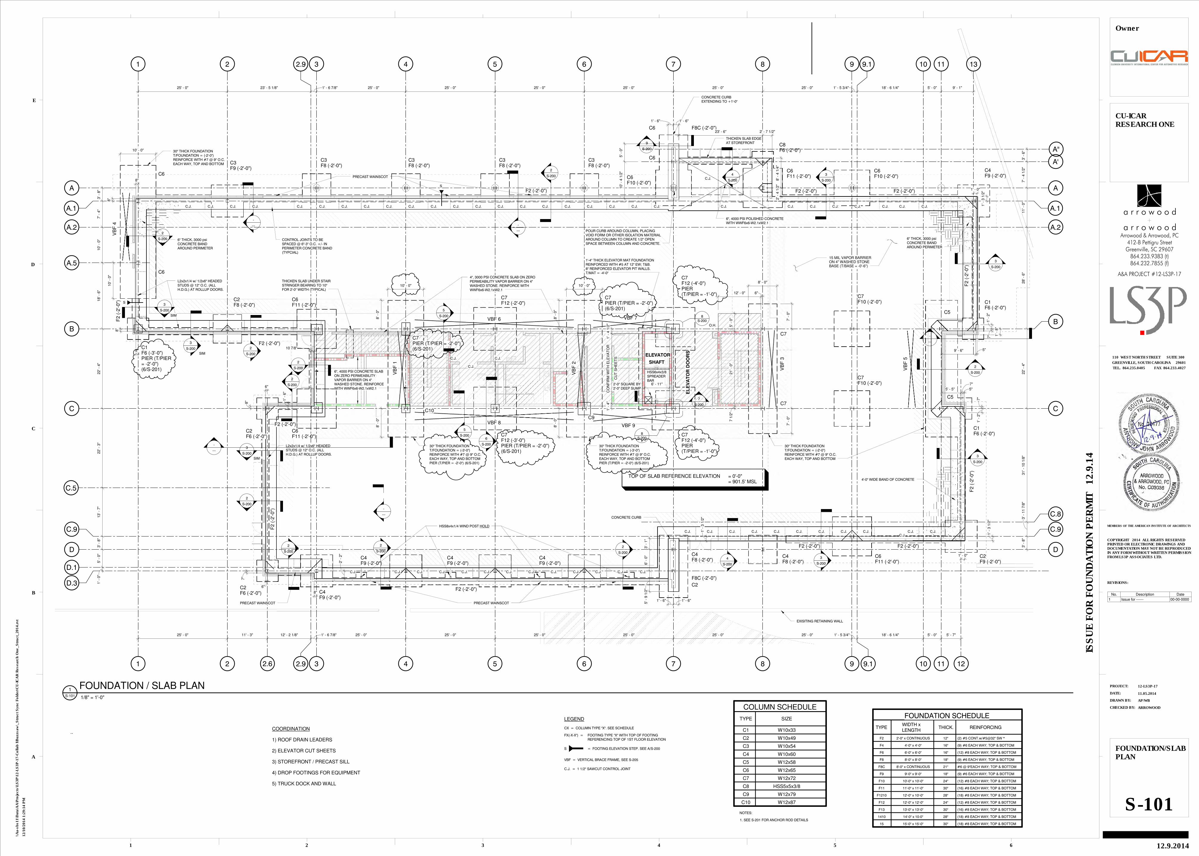
TOP OF SLAB REFERENCE ELEVATION = 0'-0"= 901.5' MSL
30" THICK FOUNDATIONT/FOUNDATION = (-2'-0")REINFORCE WITH #7 @ 9" O.C.EACH WAY, TOP AND BOTTOM
30" THICK FOUNDATIONT/FOUNDATION = (-3'-0")REINFORCE WITH #7 @ 9" O.C.EACH WAY, TOP AND BOTTOMPIER (T/PIER = -2'-0") (6/S-201)
30" THICK FOUNDATIONT/FOUNDATION = (-3'-0")REINFORCE WITH #7 @ 9" O.C.EACH WAY, TOP AND BOTTOMPIER (T/PIER = -2'-0") (6/S-201)
30" THICK FOUNDATIONT/FOUNDATION = (-2'-0")REINFORCE WITH #7 @ 9" O.C.EACH WAY, TOP AND BOTTOM
C8F6 (-2'-0")
7
S-200
PRECAST WAINSCOT PRECAST WAINSCOT
F2 (-2'-0")
F2 (-2'-0")F2 (-2'-0")
1' -
4 1
/2"
CU
T S
HE
ET
S
CO
NF
IRM
WIT
H E
LE
VA
TO
R1' -
4"
6' - 11"
THICKEN SLAB UNDER STAIRSTRINGER BEARING TO 10"FOR 2'-0" WIDTH (TYPICAL)
L2x2x1/4 w/ 1/2x6" HEADEDSTUDS @ 12" O.C. (ALLH.D.G.) AT ROLLUP DOORS.
L2x2x1/4 w/ 1/2x6" HEADEDSTUDS @ 12" O.C. (ALLH.D.G.) AT ROLLUP DOORS.
S
S
PRECAST WAINSCOT
POUR CURB AROUND COLUMN, PLACINGVOID FORM OR OTHER ISOLATION MATERIALAROUND COLUMN TO CREATE 1/2" OPENSPACE BETWEEN COLUMN AND CONCRETE.
S-200
8
S-200
8
F2 (-2'-0")
3
S-200
3
S-200
2
S-200
2
S-200
2
S-200
2
S-200
2
S-200
2
S-200
2
S-200
2
S-200
2
S-200
3
S-200
3
S-200
2
S-200
4
S-200
4
S-200
A''
6", 4000 PSI POLISHED CONCRETEWITH WWF6x6-W2.1xW2.1
3
S-200
3
S-200
SIM
SIM
3
S-200
SIM
C.J. C.J.C.J. C.J. C.J. C.J. C.J. C.J. C.J.
C.J.
C.J. C.J. C.J.
C.J.C.J.C.J.
C.J. C.J. C.J.C.J.C.J.C.J.C.J.
6
S-200
9
S-200
VBF 6 VBF 7
VBF 9VBF 8
F8C (-2'-0")
-
---
A.1 A.1
-
---
HSS8x4x1/4 WIND POST HOLD
-
---
-
---
5
S-200
5
S-200
O.H. 5' -
0"
21' -
0"
7 1
/2"
12' - 0" 6"
6"
8"
6"
8"
-
---
7"
2' -
2"
1' - 6" 1' - 6"
1' -
3 1
/2"
5' -
9 1
/2"
6' -
0"
3' -
1"
1' - 0"
1' -
3 1
/2"
7"
1' -
2"
5' - 5"
7"
5"
9' - 6" 5"
1' -
2"
7"
1' -
3 1
/2"1' - 0"
2' -
4 1
/2"
8' -
4 1
/4"
23' - 6" 2' - 7 1/2"
1' - 6" 1' - 6"
10' -
4 1
/2"
5' -
0"
8"
8"
8"
8"
10 7/8"
C.J. C.J. C.J. C.J. C.J. C.J. C.J. C.J. C.J. C.J. C.J. C.J. C.J. C.J.C.J. C.J. C.J.
CONTROL JOINTS TO BESPACED @ 6"-3" O.C. +/- INPERIMETER CONCRETE BAND(TYPCIAL)
C.J. C.J. C.J. C.J. C.J. C.J.
C.J.C.J.C.J.C.J.C.J. C.J. C.J. C.J. C.J.
C.J. C.J.
C.J.
F2
TYPE
FOUNDATION SCHEDULEWIDTH xLENGTH
THICK. REINFORCING
2'-0" x CONTINUOUS 12" (2) #5 CONT.w/#5@32" SW *
F8C 8'-0" x CONTINUOUS 21" #6 @ 9"EACH WAY; TOP & BOTTOM
F10 10'-0" x 10'-0" 24" (12) #8 EACH WAY; TOP & BOTTOM
F11 11'-0" x 11'-0" 30" (16) #8 EACH WAY; TOP & BOTTOM
F1210 12'-0" x 10'-0" 28" (18) #8 EACH WAY; TOP & BOTTOM
F8 8'-0" x 8'-0" 18" (9) #6 EACH WAY; TOP & BOTTOM
F9 9'-0" x 9'-0" 18" (9) #6 EACH WAY; TOP & BOTTOM
F6 6'-0" x 6'-0" 16" (12) #8 EACH WAY; TOP & BOTTOM
F4 4'-0" x 4'-0" 16" (9) #6 EACH WAY; TOP & BOTTOM
F12 12'-0" x 12'-0" 24" (12) #8 EACH WAY; TOP & BOTTOM
F13 13'-0" x 13'-0" 30" (16) #8 EACH WAY; TOP & BOTTOM
1410 14'-0" x 10-0" 28" (18) #8 EACH WAY; TOP & BOTTOM
15 15'-0" x 15'-0" 30" (18) #8 EACH WAY; TOP & BOTTOM
TYPE
COLUMN SCHEDULE
SIZE
NOTES:
1. SEE S-201 FOR ANCHOR ROD DETAILS
C1 W10x33
C2 W10x49
C3 W10x54
C4 W10x60
C5 W12x58
C6 W12x65
C7 W12x72
C8 HSS5x5x3/8
C9 W12x79
C10 W12x87
LEGEND
CX = COLUMN TYPE "X". SEE SCHEDULE
FX(-X-X") =
= FOOTING ELEVATION STEP. SEE A/S-200S
VBF = VERTICAL BRACE FRAME, SEE S-205
FOOTING TYPE "X" WITH TOP OF FOOTINGREFERENCING TOP OF 1ST FLOOR ELEVATION
C.J. = 1 1/2" SAWCUT CONTROL JOINT
CHECKED BY:
DRAWN BY:
DATE:
PROJECT:
REVISIONS:
MEMBERS OF THE AMERICAN INSTITUTE OF ARCHITECTS
1
A
2 3 4 5 6
B
C
D
E
COPYRIGHT 2014 ALL RIGHTS RESERVEDPRINTED OR ELECTRONIC DRAWINGS ANDDOCUMENTATION MAY NOT BE REPRODUCEDIN ANY FORM WITHOUT WRITTEN PERMISSIONFROM LS3P ASSOCIATES LTD.
TEL. 864.235.0405 FAX 864.233.4027
GREENVILLE, SOUTH CAROLINA 29601
110 WEST NORTH STREET SUITE 300
ISS
UE
FO
R F
OU
ND
AT
ION
PE
RM
IT 1
2.9
.14
12/1
0/2
014 1
:29:1
4 P
M
\\A
a-s
bs11\D
ata
\AA
\Pro
jects
\LS
3P
\12-L
S3P
-17-C
ollab
I\B
uzzsaw
\_S
tru
ct
Syn
c F
old
er\
CU
-IC
AR
Researc
h O
ne_S
tru
ct_
2014.r
vt
12-LS3P-17
11.05.2014
AP/WB
ARROWOOD
FOUNDATION/SLABPLAN
S-101
CU-ICARRESEARCH ONE
12.9.2014
Owner
864.232.7855 (f)864.233.9383 (t)
Greenville, SC 29607412-B Pettigru Street
Arrowood & Arrowood, PC
A&A PROJECT #12-LS3P-17
a r r o w o o d
a r r o w o o d
1/8" = 1'-0"S-101
1 FOUNDATION / SLAB PLAN
..COORDINATION
1) ROOF DRAIN LEADERS
2) ELEVATOR CUT SHEETS
3) STOREFRONT / PRECAST SILL
4) DROP FOOTINGS FOR EQUIPMENT
5) TRUCK DOCK AND WALL
No. Description Date
1 Issue for ------ 00-00-0000

1
1
2
2
3
3
4
4
5
5
6
6
7
7
8
8
9
9
10
10
11
11
A A
BB
C C
C.9 C.9
D D
A.5
W18X35 c=3/4"(16) W18X35 c=3/4"(16)
25' - 0" 25' - 0" 25' - 0" 25' - 0" 25' - 0" 25' - 0" 25' - 0" 25' - 0" 20' - 0" 5' - 0"
W18X
35
c=
1 1
/4"
(30)
W18X
35
c=
1 1
/4"
(30)
W18X
35
c=
1 1
/4"
(30)
W30X
148
W24X
84
(25)
W21X
55
(25)
W18X
35
c=
1 1
/4"
(30)
W18X
35
c=
1 1
/4"
(30)
W18X
35
c=
1 1
/4"
(30)
W18X
35
c=
1 1
/4"
(30)
W18X
35
c=
1 1
/4"
(30)
W18X
35
c=
1 1
/4"
(30)
W18X
35
c=
1 1
/4"
(30)
W18X
35
c=
1 1
/4"
(30)
W18X
35
c=
1 1
/4"
(30)
W18X
35
c=
1 1
/4"
(30)
W18X
35
c=
1 1
/4"
(30)
W21X
55
(26)
W18X
35
c=
1 1
/4"
(30)
W18X
35
c=
1 1
/4"
(30)
W21X
55
(26)
W18X
35
c=
1 1
/4"
(30)
W18X
35
c=
1 1
/4"
(30)
W18X
35
c=
1 1
/4"
(30)
W18X
35
c=
1 1
/4"
(30)
W18X
35
c=
1 1
/4"
(30)
W18X
35
c=
1 1
/4"
(30)
W18X
35
c=
1 1
/4"
(30)
W24X
76
(35)
W18X35 c=3/4"(16) W18X35 c=3/4"(16) W18X35 c=3/4"(16) W18X35 c=3/4"(16) W18X40 (22) W18X35 c=3/4"(16)
W16X31
W10X
12
W10X
12
W18X35 c=3/4"(16) W18X35 c=3/4"(16)
W14X
22
(10)
W14X
22
(10)
W14X
22
(10)
W14X
22
(10)
W8X
58
c=
3/4
"(1
8)
W21X62 (48) W21X62 (48) W21X62 (49)
W21X62 (48) W21X62 (48) W21X62 (49)W21X44 (49)
W16X
26
(18)
W14X
22
(18)
W14X
22
(10)
W14X
22
(10)
W14X
22
(10)
W21X
55
(18) W
12X
14
(8)
W21X
55
(18)
W14X
22
(10)
W21X
55
(18)
W21X50 (49)
W21X44 (49) W21X44 (49)
W21X44 (49) W21X44 (49)
W14X
22
(10)
W14X
22
(10)
W14X
22
(10)
W14X
22
(10)
W14X
22
(10)
W18X
35
(8)
W21X
44
c=
1 3
/4"
(54)
W21X
44
c=
1 3
/4"
(54)
W21X
44
c=
1 3
/4"
(54)
W21X
44
c=
1 3
/4"
(54)
W21X
44
c=
1 3
/4"
(54)
W21X
44
c=
1 3
/4"
(54)
W21X
44
c=
1 3
/4"
(54)
W21X
44
c=
1 3
/4"
(54)
W21X
44
c=
1 3
/4"
(54)
W21X
44
c=
1 3
/4"
(54)
W18X
35
c=
1 1
/4"
(26)
W18X
35
c=
1 1
/4"
(26)
W27X
146
c=
1 1
/4"
(16)
W18X
35
c=
1 1
/4"
(26)
W18X
35
c=
1 1
/4"
(26)
W18X
35
c=
1"
(18)
W18X
35
c=
1"
(16)
W21X44 (30)
W18X
35
c=
1 1
/4"
(26)
W18X
35
c=
1 1
/4"
(26)
W18X
35
c=
1 1
/4"
(26)
W18X
35
c=
1 1
/4"
(26)
W21X
44
c=
1 3
/4"
(54)
W21X
44
c=
1 3
/4"
(54)
W21X
44
c=
1 3
/4"
(54)
W21X
44
c=
1 3
/4"
(54)
W10
X49(P
OST)
W10
X49(P
OST)
SHAFT
ELEVATOR
VB
F 1
VB
F 3
TOP OF SLAB ELEVATION = 18'-0"BOTTOM OF DECK ELEVATION = 17'-7"FLOOR SLAB TO BE 5" (3000 PSI) CONCRETE WITHWWF 6x6-W2.9xW2.9 WITH 2"x20 GAGE GALVANIZED(G60) COMPOSITE STEEL DECK.
A.2 A.2
C.8
9.12.9
A'
VB
F 4
W16X
26
(18)
W27X
146
c=
1"
(16)
W21X
44
(18)
(T/B
EA
M =
16
'-5")
W14X61
W14X61
W14X61
W14X61
W14X48
VB
F 2
W16X
36
W14X
22
W18X35
HS
S16X
8X
3/8
CONCRETE FILLED, STEELPAN STAIRS BY MISC.METALS FABRICATOR
CONCRETE FILLED, STEELPAN STAIRS BY MISC.METALS FABRICATOR
W12X
14
(8)
HSS6x4x3/8SPREADERBEAM
D.1
2.6
C.5
D.3
D.3
12
12
13
W21X44 (16) W21X44 (16) W21X44 (16)
(LO
W)
W18X35 c=3/4"(16) W21X44 c=1"(30)
W10
x49
POST F
RO
M W
27
CANTILEVER W27 OVER COLUMN. (2)3/4" FULL DEPTH STIFFENERS IN W27WEB OVER COLUMN (NS,FS) AND ATPOST BEARING (NS, FS)
W10
x49
POST F
RO
M W
27
W18X35
CO
LUM
N B
ELOW
W18X35 W21X50 (48)
CO
LUM
N B
ELOW
MOMENTCONECTED W18X35
MOMENTCONECTEDW18X35
W24X55 c=1"(35)
W12X50
W21X44
MOMENTCONNECTED W21
W27X
146
c=
3/4
"
W10
X49
PO
ST
COLUMN BELOW
CO
LUM
N B
ELOW
VB
F5
W12X35
W12X35
W12X35
W12X35
T/BEAM = 16'-5"BEAM TO BE BELOWCANTILEVERED W14. BEAM TOATTACHED TO THE DROPPEDW27 AND THE CANTILEVEREDEND OF THE W14.
W21X44 (49)
18' -
6"
W16X
36
A''
CO
LUM
N B
ELOW
7
S-202
5
S-204
8
S-202
3
S-204
W18X35 W21X44 (16)
VBF 7
VBF 9
HS
S16X
8X
3/8
VBF 6
VBF 8
14' - 4" 6' - 4"
3
S-205
W12X
14
7
S-202
W21X44
W18X35
MOMENTCONECTED W18X35
A.1 A.1
8
S-202
4' - 9"
9' - 1" 7' - 6"
7
S-203
7
S-203
8
S-203
9
S-203
HOLD DETAILING AROUND STAIR,ELEVATOR, AND MECHANICAL SHAFTS.
(2) 3/4" FULL DEPTH STIFFENERS INW30 WEB OVER COLUMN (NS,FS)AND AT POST BEARING (NS, FS)
9
S-202
SIM
EOS9 1/2"
8
S-203
EOS1' - 8 1/2"
9
S-202
8
S-202
4' - 8"
HSS10x4x1/4 CENTERED FROMCOLUMN. HSS3x3x1/4 KICKER TOSUPPORT EDGE ANGLE.
9
S-202EOS
1' - 3 1/2"
HSS12x6x1/4
HSS12x4x1/4
CANTILEVERW30 OVERCOLUMN
6' - 5" 4' - 7"
W12x14 4' - 6" 4' - 6 7/8" 4' - 6"
HSS12X4X1/4W12x14
5' - 2" W14X
22
EOS5' - 9"
9
S-202
6' -
0"
6' -
0"
6' -
0"
6' -
0"
5' -
6"
5' -
6"
6' -
0"
6' -
0"
6' -
0"
6' -
0"
2' -
11 1
/2"
2' -
11 1
/2"
3' -
6"
6' -
0"
6' -
0"
6' -
0"
6' -
0"
6' -
0"
6' -
0"
4' -
6"
3' -
6"
8' - 4" 8' - 4" 8' - 4"
5' -
11 1
/4"
7' -
0"
7' -
0"
7' -
0"
6' -
0"
6' -
6 3
/4"
HSS10x4x1/4 CENTERED FROMCOLUMN. HSS3x3x1/4 KICKER TOSUPPORT EDGE ANGLE.
-
---
-
---
MOMENTCONNECTED W12(T/W12 = 16'-5")
W14X22
W14 FILLER BEAM ABOVE
10
S-208
11
S-208
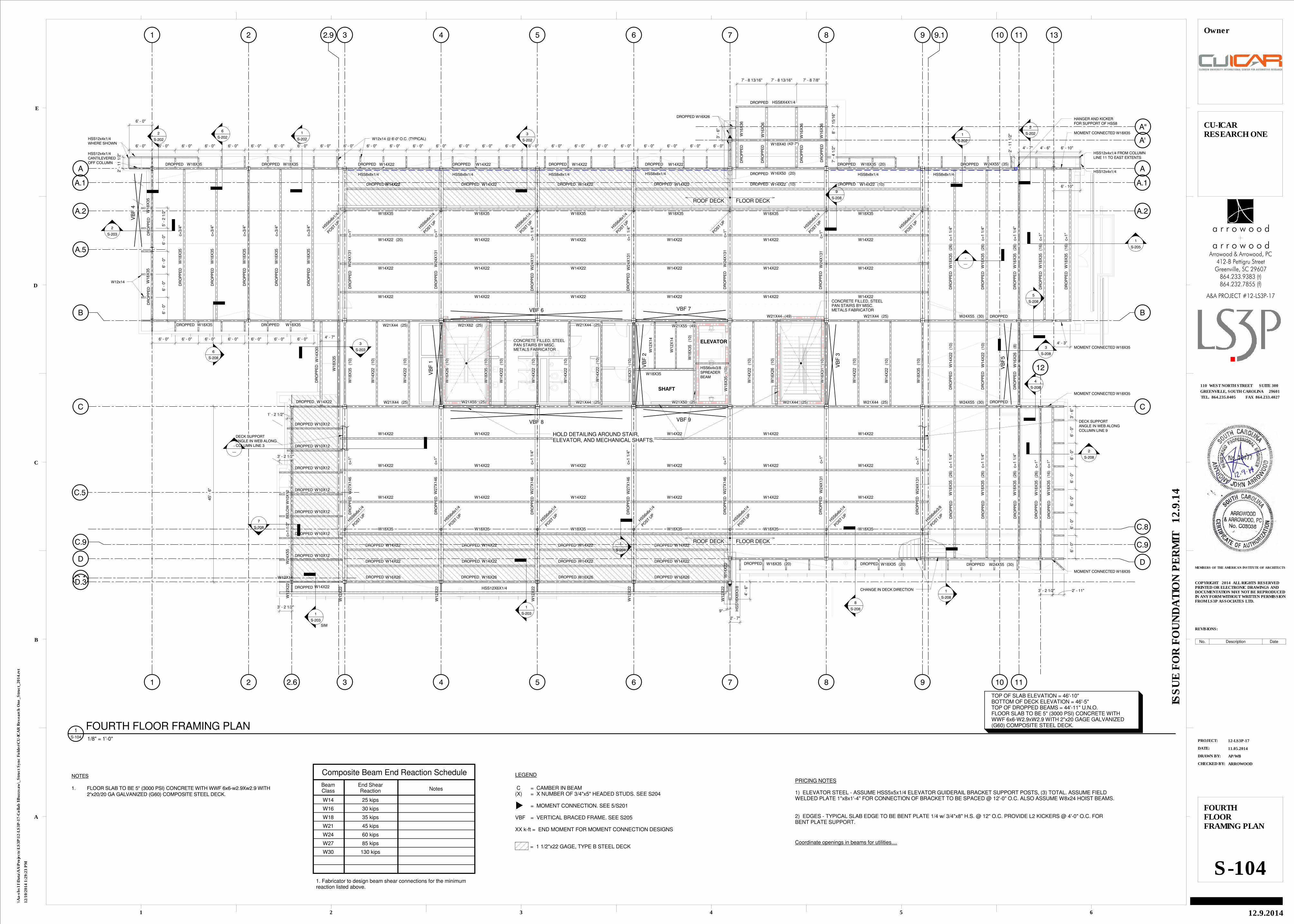
BeamClass
W14
End ShearReaction
25 kips
Notes
Composite Beam End Reaction Schedule
1. Fabricator to design beam shear connections for the minimumreaction listed above.
W16 30 kips
W18 35 kips
W21 45 kips
W24 60 kips
W27 85 kips
W30 130 kips
NOTES
1. FLOOR SLAB TO BE 5" (3000 PSI) CONCRETE WITH WWF 6x6-w2.9Xw2.9 WITH2"x20/20 GA GALVANIZED (G60) COMPOSITE STEEL DECK.
LEGEND
C = CAMBER IN BEAM(X) = X NUMBER OF 3/4"x5" HEADED STUDS. SEE S204
= MOMENT CONNECTION. SEE 5/S201
VBF = VERTICAL BRACED FRAME. SEE S205
XX k-ft = END MOMENT FOR MOMENT CONNECTION DESIGNS
= 1 1/2"x22 GAGE, TYPE B STEEL DECK
CHECKED BY:
DRAWN BY:
DATE:
PROJECT:
REVISIONS:
MEMBERS OF THE AMERICAN INSTITUTE OF ARCHITECTS
1
A
2 3 4 5 6
B
C
D
E
COPYRIGHT 2014 ALL RIGHTS RESERVEDPRINTED OR ELECTRONIC DRAWINGS ANDDOCUMENTATION MAY NOT BE REPRODUCEDIN ANY FORM WITHOUT WRITTEN PERMISSIONFROM LS3P ASSOCIATES LTD.
TEL. 864.235.0405 FAX 864.233.4027
GREENVILLE, SOUTH CAROLINA 29601
110 WEST NORTH STREET SUITE 300
ISS
UE
FO
R F
OU
ND
AT
ION
PE
RM
IT 1
2.9
.14
12/1
0/2
014 1
:29:1
7 P
M
\\A
a-s
bs11\D
ata
\AA
\Pro
jects
\LS
3P
\12-L
S3P
-17-C
ollab
I\B
uzzsaw
\_S
tru
ct
Syn
c F
old
er\
CU
-IC
AR
Researc
h O
ne_S
tru
ct_
2014.r
vt
12-LS3P-17
11.05.2014
AP/WB
ARROWOOD
SECONDFLOORFRAMING PLAN
S-102
CU-ICARRESEARCH ONE
12.9.2014
Owner
1/8" = 1'-0"S-102
1 SECOND FLOOR FRAMING PLAN
864.232.7855 (f)864.233.9383 (t)
Greenville, SC 29607412-B Pettigru Street
Arrowood & Arrowood, PC
A&A PROJECT #12-LS3P-17
a r r o w o o d
a r r o w o o d
.. PRICING NOTES
1) ELEVATOR STEEL - ASSUME HSS5x5x1/4 ELEVATOR GUIDERAIL BRACKET SUPPORT POSTS, (3) TOTAL. ASSUME FIELDWELDED PLATE 1"x8x1'-4" FOR CONNECTION OF BRACKET TO BE SPACED @ 12'-0" O.C. ALSO ASSUME W8x24 HOIST BEAMS.
2) EDGES - TYPICAL SLAB EDGE TO BE BENT PLATE 1/4 w/ 3/4"x8" H.S. @ 12" O.C. PROVIDE L2 KICKERS @ 4'-0" O.C. FORBENT PLATE SUPPORT.
COORDINATION
1) OPENING IN BEAMS FOR CONDUIT ROUTING
No. Description Date

1
1
2
2
3
3
4
4
5
5
6
6
7
7
8
8
9
9
10
10
11
11
A A
BB
C C
C.9C.9
D D
A.5
W18X
35
W18X
35
W18X35 c=3/4"(16) W18X35 c=3/4"(16) W18X35 c=3/4"(16)W
18X
35
c=
1 1
/4"
(30)
W18X
35
c=
1 1
/4"
(30)
W18X
35
c=
1 1
/4"
(30)
W18X
35
c=
1 1
/4"
(30)
W18X
35
c=
1 1
/4"
(30)
W18X
35
c=
1 1
/4"
(30)
W18X35 c=3/4"(16) W18X35 c=3/4"(16)
W21X44 (49)
W18X35 c=3/4"(16) W18X35 c=3/4"(16)
W21X55 (48)W21X62 (48)
W18X
35
c=
1 1
/4"
(30)
W18X
35
c=
1 1
/4"
(30)
W18X
35
c=
1 1
/4"
(30)
W18X
35
c=
1 1
/4"
(30)
W18X
35
c=
1 1
/4"
(30)
W18X
35
c=
1 1
/4"
(30)
W18X
35
c=
1 1
/4"
(30)
W18X
35
c=
1 1
/4"
(30)
W18X
35
c=
1 1
/4"
(30)
W18X
35
c=
1 1
/4"
(30)
W18X
35
c=
1 1
/4"
(30)
W21X
55
(26)
W18X
35
c=
1 1
/4"
(30)
W18X
35
c=
1 1
/4"
(30)
W21X
55
(26)
W18X
35
c=
1 1
/4"
(30)
W18X
35
c=
1 1
/4"
(30)
W18X
35
c=
1 1
/4"
(30)
W18X
35
c=
1 1
/4"
(30)
W18X40 (22) W18X35 c=3/4"(16)W18X35 c=3/4"(16)
W21X55 (49) W21X44 (49)
W21X44 (49)
W24X55 (35)
W24X
76
(35)
W18X
35
c=
1 1
/4"
(30)
W21X44 (49)
W14X
22
(10)
W14X
22
(10)
W14X
22
(10)
W14X
22
(10)
W18X
35
(10)
W16X
26
(8)
W14X
22
(10)
W14X
22
(10)
W14X
22
(10)
W14X
22
(10)
W18X
35
(10)
W21X55 (48)W21X55 (48)W21X55 (48)W21X50 (48)
W18X
35
(10)
W14X
22
(10)
W18X
35
(10)
W21X50 (48)
W14X
22
(10)
W14X
22
(10)
W14X
22
(10)
W14X
22
(10)
W14X
22
(10)
W18X
35
(10)
W21X44 (49) W21X44 (49)
W21X
44
c=
1 1
/2"
(54)
W21X
44
c=
1 1
/2"
(54)
W21X
44
c=
1 1
/2"
(54)
W21X
44
c=
1 1
/2"
(54)
W21X
44
c=
1 1
/2"
(54)
W21X
44
c=
1 1
/2"
(54)
W21X
44
c=
1 1
/2"
(54)
W21X
44
c=
1 1
/2"
(54)
W21X
44
c=
1 1
/2"
(54)
W21X
44
c=
1 1
/2"
(54)
W21X
44
c=
1 1
/2"
(54)
W21X
44
c=
1 1
/2"
(54)
W21X
44
c=
1 1
/2"
(54)
W21X
44
c=
1 1
/2"
(54)
W18X
35
c=
1 1
/4"
(26)
W18X
35
c=
1 1
/4"
(26)
W18X
35
c=
1 1
/4"
(26)
W18X
35
c=
1 1
/4"
(26)
W18X
35
c=
1 1
/4"
(26)
W18X
35
c=
1 1
/4"
(26)
W21X44 (30)
W18X
35
c=
1 1
/4"
(26)
W18X
35
c=
1 1
/4"
(26)
W18X
35
c=
1 1
/4"
(26)
W18X
35
c=
1"
(26)
W18X
35
(13)
W21X44 c=1"(30)W21X44 c=1"(30)
W16X31
W10X
12
W10X
12
SHAFT
ELEVATOR
VB
F 1
VB
F 3
TOP OF SLAB ELEVATION = 32'-0"BOTTOM OF DECK ELEVATION = 31'-7"FLOOR SLAB TO BE 5" (3000 PSI) CONCRETE WITHWWF 6x6-W2.9xW2.9 WITH 2"x20 GAGE GALVANIZED(G60) COMPOSITE STEEL DECK.
A.2 A.2
C.8
9.12.9
A'
W18X
35
(10)
W16X26
W12X
14
(8)
W18X
35
c=
3/4
"(1
3)
VB
F 4
W27X
161
c=
1"
(T/B
EA
M =
31
' - 5
")
W12X50
W14X
22
VB
F 2
CONCRETE FILLED, STEELPAN STAIRS BY MISC.METALS FABRICATOR
CONCRETE FILLED, STEELPAN STAIRS BY MISC.METALS FABRICATOR
W12X
14
(8)
HSS6x4x3/8SPREADERBEAM
D.1
2.6
C.5
D.3
12
13
W18X35
W18X35
MOMENT CONNECT W18X35
MOMENT CONNECT W18X35
W16X
26
MOMENTCONNECTED W21
MOMENTCONNECTED W12(T/W12 = 30'-5")
4' - 5" 4' - 7" 4' - 6" 7' - 8"
4' - 5"
VB
F5
W14X90
W14X74
W14X61
W14X74
W12X35
W12X50
W12X50
W12X50
T/BEAM = 30'-5"BEAM TO BE BELOWCANTILEVERED W14. BEAM TOATTACHED TO THE DROPPEDW27 AND THE CANTILEVEREDEND OF THE W14.
W14X48
W16X
36
W16X
36
A''
5
S-204
4
S-202
5
S-2024
S-202
SIM
3
S-204
W21X44 (16) W21X44 (16) W21X44 (16) W21X44 (16)
VBF 7
VBF 9
HS
S16X
8X
3/8
HS
S16X
8X
3/8
VBF 6
VBF 8
W21X44
W14X48
14' - 4" 6' - 5" 3' - 4"
W12X
14
W12X50
W18X35
A.1 A.1
4' - 1"
4
S-203
4
S-203
5
S-202
5
S-203
5
S-203
6
S-203
6
S-203
SIM
2
S-205
HOLD DETAILING AROUND STAIR,ELEVATOR, AND MECHANICAL SHAFTS.
4' - 8"
SIM
SECTION CUT APPLIS FROMCOLUMN LINE 1 TO 22'-11"EAST OF COLUMN LINE 1
W12x14HSS12x4x1/4 BAND
2' -
11 1
/2"
5' -
6"
6' -
0"
6' -
0"
6' -
0"
6' -
0"
3' -
6"
8' - 4" 8' - 4" 8' - 4"
1' -
7"
4' -
8"
6' -
10"
6' -
11"
6' -
11"
6' -
7"
6' -
0"
-
---
W14X22
W14 FILLER BEAM ABOVE
12
S-208
13
S-208
BeamClass
W14
End ShearReaction
25 kips
Notes
Composite Beam End Reaction Schedule
1. Fabricator to design beam shear connections for the minimumreaction listed above.
W16 30 kips
W18 35 kips
W21 45 kips
W24 60 kips
W27 85 kips
W30 130 kips
NOTES
1. FLOOR SLAB TO BE 5" (3000 PSI) CONCRETE WITH WWF 6x6-w2.9Xw2.9 WITH2"x20/20 GA GALVANIZED (G60) COMPOSITE STEEL DECK.
LEGEND
C = CAMBER IN BEAM(X) = X NUMBER OF 3/4"x5" HEADED STUDS. SEE S204
= MOMENT CONNECTION. SEE 5/S201
VBF = VERTICAL BRACED FRAME. SEE S205
XX k-ft = END MOMENT FOR MOMENT CONNECTION DESIGNS
= 1 1/2"x22 GAGE, TYPE B STEEL DECK
CHECKED BY:
DRAWN BY:
DATE:
PROJECT:
REVISIONS:
MEMBERS OF THE AMERICAN INSTITUTE OF ARCHITECTS
1
A
2 3 4 5 6
B
C
D
E
COPYRIGHT 2014 ALL RIGHTS RESERVEDPRINTED OR ELECTRONIC DRAWINGS ANDDOCUMENTATION MAY NOT BE REPRODUCEDIN ANY FORM WITHOUT WRITTEN PERMISSIONFROM LS3P ASSOCIATES LTD.
TEL. 864.235.0405 FAX 864.233.4027
GREENVILLE, SOUTH CAROLINA 29601
110 WEST NORTH STREET SUITE 300
ISS
UE
FO
R F
OU
ND
AT
ION
PE
RM
IT 1
2.9
.14
12/1
0/2
014 1
:29:1
9 P
M
\\A
a-s
bs11\D
ata
\AA
\Pro
jects
\LS
3P
\12-L
S3P
-17-C
ollab
I\B
uzzsaw
\_S
tru
ct
Syn
c F
old
er\
CU
-IC
AR
Researc
h O
ne_S
tru
ct_
2014.r
vt
12-LS3P-17
11.05.2014
AP/WB
ARROWOOD
THIRD FLOORFRAMING PLAN
S-103
CU-ICARRESEARCH ONE
12.9.2014
Owner
864.232.7855 (f)864.233.9383 (t)
Greenville, SC 29607412-B Pettigru Street
Arrowood & Arrowood, PC
A&A PROJECT #12-LS3P-17
a r r o w o o d
a r r o w o o d
1/8" = 1'-0"S-103
1 THIRD FLOOR FRAMING PLAN
PRICING NOTES
1) ELEVATOR STEEL - ASSUME HSS5x5x1/4 ELEVATOR GUIDERAIL BRACKET SUPPORT POSTS, (3) TOTAL. ASSUME FIELDWELDED PLATE 1"x8x1'-4" FOR CONNECTION OF BRACKET TO BE SPACED @ 12'-0" O.C. ALSO ASSUME W8x24 HOISTBEAMS.
No. Description Date
1
1
2
2
3
3
4
4
5
5
6
6
7
7
8
8
9
9
10
10
11
11
A A
B B
C C
C.9 C.9
D D
A.5
W18X35
W18X
35
c=
3/4
"
W18X
35
c=
3/4
"
W18X
35
c=
3/4
"
W18X
35
c=
3/4
"
W18X
35
c=
3/4
"
W18X35
W18X35 W18X35
W18X
35
W18X
35
W14X22 W14X22 W14X22
W21X44 (25) W21X62 (25) W21X44 (25)
W14X22
W21X55 (49)
W18X40
W18X35 (20) W24X55 (35)
W18X
35
c=
1 1
/4"
(26)
W18X
35
c=
1 1
/4"
(26)
W18X
35
c=
1 1
/4"
(26)
W18X
35
c=
1"
(16)
W18X
35
c=
1"
(16)
W21X44 (49) W21X44 (25) W24X55 (30)W
14X
30
W18X
35
(10)
W14X
22
(10)
W14X
22
(10)
W21X44 (25)
W16X
26
(10)
W16X
31
(10)
W18X
35
(10)
W14X
22
(10)
W14X
22
(10)
W14X
22
(10)
W14X
22
(10)
W18X
35
(10)
W14X
22
(10)
W16X
31
(10)
W14X
22
(10)
W14X
22
(10)
W18X
35
(10)
W14X
22
(10)
W14X
22
(10)
W21X44 (25) W24X55 (30)W21X44 (25)
W16X
26
(8)
W18X
35
c=
1"
(16)
W18X
35
c=
1 1
/4"
(26)
W18X
35
c=
1 1
/4"
(26)
W18X
35
c=
1 1
/4"
(26)
W24X
131
c=
1"
W27X
146
c=
1"
W24X
131
c=
1"
W27X
146
c=
1"
W27X
146
c=
1 1
/4"
W27X
146
c=
1 1
/4"
W24X
55
c=
1 1
/2"
W27X
146
c=
1"
HANGER AND KICKERFOR SUPPORT OF HSS8
SHAFT
ELEVATOR
VB
F 1
VB
F 3
W21X55 (25) W21X44 (25) W21X50 (25)
TOP OF SLAB ELEVATION = 46'-10"BOTTOM OF DECK ELEVATION = 46'-5"TOP OF DROPPED BEAMS = 44'-11" U.N.O.FLOOR SLAB TO BE 5" (3000 PSI) CONCRETE WITHWWF 6x6-W2.9xW2.9 WITH 2"x20 GAGE GALVANIZED(G60) COMPOSITE STEEL DECK.
A.2 A.2
C.8
9.12.9
A'
W18X
35
c=
1"
(26)
W16X
26
(10)W
18X
35
(10)
W12X
14
W18X35
VB
F 4
VB
F 2
HSS8X4X1/4
(43'-7")
CONCRETE FILLED, STEELPAN STAIRS BY MISC.METALS FABRICATOR
CONCRETE FILLED, STEELPAN STAIRS BY MISC.METALS FABRICATOR
DROPPED DROPPED DROPPED DROPPED DROPPED DROPPED DROPPED DROPPED
DR
OP
PE
D
DR
OP
PE
D
DR
OP
PE
D
DR
OP
PE
D
DR
OP
PE
D
DROPPED
DR
OP
PE
D
DR
OP
PE
D
DR
OP
PE
D
DROPPED
DR
OP
PE
D
DR
OP
PE
D
DR
OP
PE
D
DR
OP
PE
D
DR
OP
PE
D
DROPPED W24X55 (30)DROPPED
DROPPED
DROPPED
DR
OP
PE
DD
RO
PP
ED
DR
OP
PE
D
DROPPED DROPPED
DR
OP
PE
D
DR
OP
PE
D
DR
OP
PE
D
DR
OP
PE
D
DR
OP
PE
D
BE
LO
W W
10
X1
2
DROPPED W14X22
W14X22DROPPED
DECK SUPPORTANGLE IN WEB ALONGCOLUMN LINE 3
DECK SUPPORTANGLE IN WEB ALONGCOLUMN LINE 9
W16X
36
W16X
36
W16X
36
W16X
36
DR
OP
PE
D
DR
OP
PE
D
DROPPED
W18X35 (20)
DR
OP
PE
D
DR
OP
PE
D
DR
OP
PE
D
DR
OP
PE
D
DR
OP
PE
D
DR
OP
PE
D
DR
OP
PE
D
W12X
14
HSS6x4x3/8SPREADERBEAM
D.1
2.6
C.5
D.3
12
13
MOMENT CONNECTED W18X35
MOMENT CONNECTED W18X35
MOMENT CONNECTED W18X35
MOMENT CONNECTED W18X35
VB
F5
W18X35
W14X22
W14X22
W14X22W14X22
W14X22
W14X22
W18X35
W14X22
W14X22
W14X22
W18X35
W14X22
W14X22
W14X22
W18X35
W14X22
W14X22
W14X22
W18X35
W14X22
W14X22
W14X22
W18X35
W24X
131
c=
1"
W24X
131
c=
1"
W24X
131
c=
1"
W24X
131
c=
1 1
/4"
W24X
131
c=
1 1
/4"
W24X
131
c=
1"
DR
OP
PE
D
DR
OP
PE
D
DR
OP
PE
D
DR
OP
PE
D
DR
OP
PE
D
DR
OP
PE
D
W18X35
W14X22
W14X22
W14X22W14X22
W14X22
W14X22
W16X50 (20)
W14X22
W14X22
W14X22
W18X35
W14X22
W14X22
W14X22
W18X35
W14X22
W14X22
W14X22
W18X35
W14X22
W14X22
W14X22 (20)
W18X35
A''
W14X22W14X22 W14X22 W14X22 W14X22 W14X22 (10)DROPPEDDROPPEDDROPPED DROPPED DROPPED
POST
UP
POST
UP
POST
UP
POST
UP
POST
UP
POST
UP
HSS6x
6x1/
4
POST
UP
POST
UP
HSS6x
6x1/
4
POST
UP
POST
UP
POST
UP
POST
UP
POST
UP
HSS6x
6x3/
8
POST
UP
1
S-202
2
S-2023
S-202
6
S-202
ROOF DECK FLOOR DECK
6
S-208
1
S-208
2
S-208
3
S-208
4
S-208
5
S-208
1
S-204
HSS6x
6x1/
4
HSS6x
6x1/
4
HSS6x
6x1/
4
HSS6x
6x1/
4
HSS6x
6x1/
4
HSS6x
6x1/
4
HSS6x
6x1/
4
HSS6x
6x1/
4
HSS6x
6x1/
4
HSS6x
6x1/
4
45' -
6"
W10X12DROPPED
W10X12DROPPED
W10X12DROPPED
W10X12DROPPED
W10X12DROPPED
W10X12DROPPED
W10X12DROPPED
W16X26 W16X26 W16X26 W16X26 W14X
22
W14X22
W14X22
DROPPED
DROPPED
W14X22
W14X22
DROPPED
DROPPED
W14X22
W14X22
DROPPED
DROPPED
W14X22
W14X22
DROPPED
VBF 7
VBF 9
DROPPED W18X35 (20)
ROOF DECK FLOOR DECK
W14X22 (10)DROPPED
W18X35
DR
OP
PE
D
DR
OP
PE
D
7' -
4 1
/2"
8' -
7 1
5/1
6"
DROPPED
7' - 8 13/16" 7' - 8 13/16" 7' - 8 7/8"
HS
S16X
8X
3/8
DROPPEDDROPPEDDROPPED
DROPPED W16X26
VBF 6
VBF 8
HSS8x8x1/4HSS8x8x1/4HSS8x8x1/4HSS8x8x1/4HSS8x8x1/4HSS8x8x1/4
A.1 A.1
4' - 3"
3' - 2 1/2"
1
S-203
1
S-202
2
S-202
2
S-203
3
S-203
W18X
35
1
S-205
HOLD DETAILING AROUND STAIR,ELEVATOR, AND MECHANICAL SHAFTS.
W12X14
3' - 2 1/2"
1' - 2 1/2"
4' - 7"
HSS12x4x1/4CANTILEVEREDOFF COLUMN
HSS12x4x1/4WHERE SHOWN
W12x14
6' - 0"
W12x14 @ 6'-0" O.C. (TYPICAL)
6' - 10"
HSS12x4x1/4 FROM COLUMNLINE 11 TO EAST EXTENTS
HSS12x4x1/4
2' -
11 1
/2"
6' - 0" 6' - 0" 6' - 0" 6' - 0" 6' - 0" 6' - 0" 6' - 0" 6' - 0" 6' - 0" 6' - 0" 6' - 0" 6' - 0" 6' - 0" 6' - 0" 6' - 0" 6' - 0" 6' - 0" 6' - 0" 6' - 0" 6' - 0" 6' - 0" 6' - 0" 6' - 0" 6' - 0" 6' - 0" 6' - 0"
2' -
11 1
/2"
4' - 7" 4' - 6" 6' - 10"
4' -
6"
3' -
6"
7
S-208
1
S-203
SIM
8
S-208
CHANGE IN DECK DIRECTION
2' - 7"
2' - 11"
6' -
0"
6' -
0"
6' -
0"
6' -
0"
6' -
0"
6' -
0"
3' -
6"
9"
HSS12X6X1/4
3' - 2 1/2"
W12X
22
W12X
22
W12X
22
W12X
22
W12X
22
W12X
22
6' - 0" 6' - 0" 6' - 0" 6' - 0" 6' - 0" 6' - 0" 6' - 0"
5' -
2 1
/2"
6' -
0"
6' -
0"
6' -
0"
6' -
0"
-
---
-
---
9
S-208
BeamClass
W14
End ShearReaction
25 kips
Notes
Composite Beam End Reaction Schedule
1. Fabricator to design beam shear connections for the minimumreaction listed above.
W16 30 kips
W18 35 kips
W21 45 kips
W24 60 kips
W27 85 kips
W30 130 kips
NOTES
1. FLOOR SLAB TO BE 5" (3000 PSI) CONCRETE WITH WWF 6x6-w2.9Xw2.9 WITH2"x20/20 GA GALVANIZED (G60) COMPOSITE STEEL DECK.
LEGEND
C = CAMBER IN BEAM(X) = X NUMBER OF 3/4"x5" HEADED STUDS. SEE S204
= MOMENT CONNECTION. SEE 5/S201
VBF = VERTICAL BRACED FRAME. SEE S205
XX k-ft = END MOMENT FOR MOMENT CONNECTION DESIGNS
= 1 1/2"x22 GAGE, TYPE B STEEL DECK
CHECKED BY:
DRAWN BY:
DATE:
PROJECT:
REVISIONS:
MEMBERS OF THE AMERICAN INSTITUTE OF ARCHITECTS
1
A
2 3 4 5 6
B
C
D
E
COPYRIGHT 2014 ALL RIGHTS RESERVEDPRINTED OR ELECTRONIC DRAWINGS ANDDOCUMENTATION MAY NOT BE REPRODUCEDIN ANY FORM WITHOUT WRITTEN PERMISSIONFROM LS3P ASSOCIATES LTD.
TEL. 864.235.0405 FAX 864.233.4027
GREENVILLE, SOUTH CAROLINA 29601
110 WEST NORTH STREET SUITE 300
ISS
UE
FO
R F
OU
ND
AT
ION
PE
RM
IT 1
2.9
.14
12/1
0/2
014 1
:29:2
3 P
M
\\A
a-s
bs11\D
ata
\AA
\Pro
jects
\LS
3P
\12-L
S3P
-17-C
ollab
I\B
uzzsaw
\_S
tru
ct
Syn
c F
old
er\
CU
-IC
AR
Researc
h O
ne_S
tru
ct_
2014.r
vt
12-LS3P-17
11.05.2014
AP/WB
ARROWOOD
FOURTHFLOORFRAMING PLAN
S-104
CU-ICARRESEARCH ONE
12.9.2014
Owner
864.232.7855 (f)864.233.9383 (t)
Greenville, SC 29607412-B Pettigru Street
Arrowood & Arrowood, PC
A&A PROJECT #12-LS3P-17
a r r o w o o d
a r r o w o o d
1/8" = 1'-0"S-104
1 FOURTH FLOOR FRAMING PLAN
PRICING NOTES
1) ELEVATOR STEEL - ASSUME HSS5x5x1/4 ELEVATOR GUIDERAIL BRACKET SUPPORT POSTS, (3) TOTAL. ASSUME FIELDWELDED PLATE 1"x8x1'-4" FOR CONNECTION OF BRACKET TO BE SPACED @ 12'-0" O.C. ALSO ASSUME W8x24 HOIST BEAMS.
2) EDGES - TYPICAL SLAB EDGE TO BE BENT PLATE 1/4 w/ 3/4"x8" H.S. @ 12" O.C. PROVIDE L2 KICKERS @ 4'-0" O.C. FORBENT PLATE SUPPORT.
Coordinate openings in beams for utilities....
No. Description Date
3
3
4
4
5
5
6
6
7
7
8
8
9
9
A A
B B
C C
W16X31 W18X50 W18X50 W16X26W18X50
W16X26
W18X50
W18X50 W18X50
W12X
26
W16X
26
W16X
26
W16X
26
W16X
26
VB
F 1
VB
F 3
A.2 A.2
C.8 C.8
9.1
9.1
2.9
2.9
HSS10x4x3/8 BAND
HSS10x4x3/8 BAND
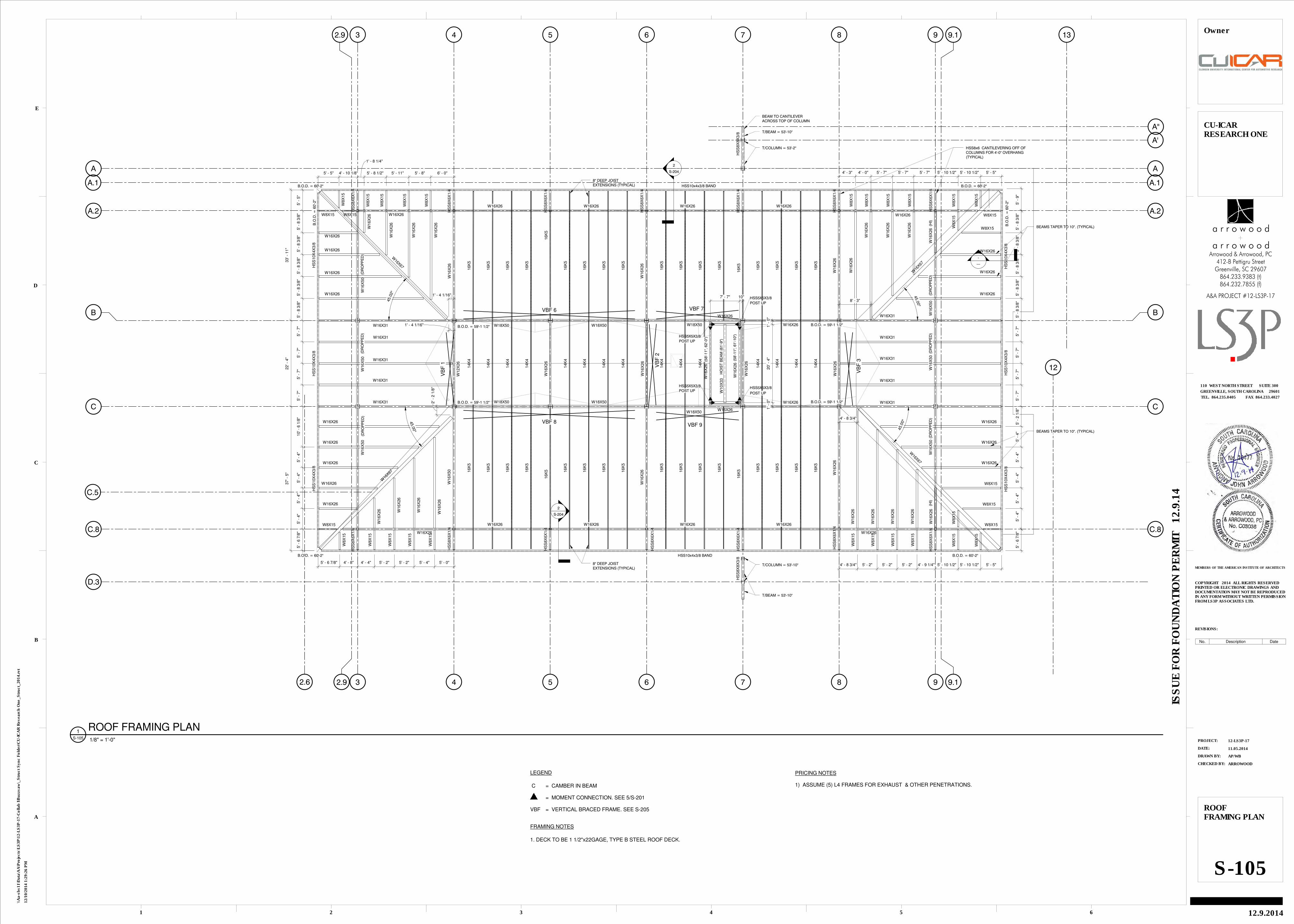
HSS8x6 CANTILEVERING OFF OFCOLUMNS FOR 4'-0" OVERHANG(TYPICAL)
BEAMS TAPER TO 10". (TYPICAL)
W16X
26
W16X31
W16X
50
W16X
50
W16X
26
W16X
50
W16X
26
W16X26
W16X26 W16X26 W16X26 W16X26
W16X26
W16X
26
16K
5
W16X
26
16K
5
W16X
50
16K
5
W16X
26
16K
5
W16X26 W16X26 W16X26 W16X26
W16X
26
W16X
26
A'
W16X
26
W16X
26
W16X31
W8X15
W16X26
W16X26
W16X26
W16X26
W8X15
W8X15
HS
S8X
8X
3/8
HS
S8X
8X
3/8
37' -
5"
22' -
4"
33' -
11"
W8X15
W16X
26
W16X
26
W16X
26
16K
5
16K
5
16K
5
16K
5
16K
5
16K
5
16K
5
16K
5
16K
5
16K
5
16K
5
16K
5
16K
5
16K
5
16K
5
16K
5
W16
X67
16K
5
16K
5
16K
5
16K
5
16K
5
16K
5
16K
5
16K
5
16K
5
16K
5
16K
5
16K
5
16K
5
16K
5
16K
5
16K
5
W16X67
14K
4
14K
4
14K
4
14K
4
14K
4
14K
4
14K
4
14K
4
14K
4
14K
4
14K
4
14K
4
14K
4
14K
4
14K
4
4' - 8 3/4" 5' - 2" 5' - 2" 5' - 2" 4' - 9 1/4" 5' - 10 1/2" 5' - 10 1/2" 5' - 5"
5' -
6 7
/8"
B.O.D. = 60'-2"
B.O.D. = 60'-2"
B.O.D. = 59'-1 1/2"
B.O.D. = 60'-2"
B.O.D. = 60'-2"
B.O.D. = 59'-1 1/2"
B.O.D. = 59'-1 1/2"
B.O.D. = 59'-1 1/2"
HSS5X5X3/8
HSS5X5X3/8
HSS5X5X3/8 HSS5X5X3/8
POST UP
POST UP
POST UP
POST UP
W16X26
W16X
26
W16X
26
W10X
33
W16X26
HO
IST
BE
AM
(6
1'-9
")
(58
'-11
", 6
2'-0
")
(58
'-11
", 6
1'-1
0")
2.6
C.5
D.3
12
13
W16X31
A''
2
S-204
VBF 7
VBF 9
W16X
26
W16X31W
16X
50
W16X
26
W16X
26
W16X26
W16X26
W16X
26
W16X
26
W16X26
W16X26
W16X26
W16X26
W16X26
W16X26
W16X26
W16X26
W16X
26
W16X
26
W16X
26
W16X67
W16
X67
W16X
50
W16X
50
W16X31
VB
F 2
T/BEAM = 53'-10"
T/COLUMN = 53'-10"
T/BEAM = 53'-10"
T/COLUMN = 53'-2"
VBF 6
VBF 8
BEAM TO CANTILEVERACROSS TOP OF COLUMN
HS
S8X
6X
1/4
HS
S8X
6X
1/4
HS
S8X
6X
1/4
HS
S8X
6X
1/4
HS
S8X
6X
1/4
HS
S8X
6X
1/4
HS
S8X
6X
1/4
HS
S8X
6X
1/4
HS
S8X
6X
1/4
HS
S8X
6X
1/4
8" DEEP JOISTEXTENSIONS (TYPICAL)
8" DEEP JOISTEXTENSIONS (TYPICAL)A.1 A.1
2
S-204
BEAMS TAPER TO 10". (TYPICAL)
5' -
9"
8' - 3"
1' - 4 1/16"
(DR
OP
PE
D)
(DR
OP
PE
D)
(DR
OP
PE
D)
(DR
OP
PE
D)
45.0
2°
45.0
0°
45.0
0°
45.0
0°
(DR
OP
PE
D)
(DR
OP
PE
D)
W16X26
4' - 3" 4' - 0" 5' - 7" 5' - 7" 5' - 7" 5' - 10 1/2" 5' - 10 1/2" 5' - 5"
W16X31
4' - 8 3/4"
W8X
15
W8X15
W8X
15
W8X
15
W8X
15
W16X
26
W8X
15
W8X
15
W8X
15
W8X
15
HS
S8X
6X
1/4
W8X
15
W8X
15
HS
S8X
6X
1/4
W8X
15
W8X
15
W8X
15
W8X
15
(HI)
W16X
26
(HI)
5' -
8 3
/8"
5' -
8 3
/8"
5' -
8 3
/8"
5' -
8 3
/8"
5' -
8 3
/8"
5' -
7"
5' -
7"
5' -
7"
5' -
7"
5' -
2 1
/8"
5' -
4"
5' -
4"
5' -
4"
5' -
4"
5' -
4"
HS
S8X
6X
1/4
W8X
15
W8X
15
W8X
15
W8X
15
W8X15
W8X
15
W8X
15
W8X
15
W8X
15
W8X
15
W8X15
W8X
15
HS
S8X
6X
1/4
1' - 4 1/16"
5' - 6 7/8" 4' - 8" 4' - 4" 5' - 2" 5' - 2" 5' - 4" 5' - 0"
5' -
6 7
/8"
5' -
4"
5' -
4"
5' -
4"
5' -
4"
10' -
6 1
/8"
5' -
7"
5' -
7"
5' -
7"
5' -
7"
5' -
8 3
/8"
5' -
8 3
/8"
5' -
8 3
/8"
5' -
8 3
/8"
5' -
8 3
/8"
5' -
5"
5' - 5" 4' - 10 1/8"
1' - 8 1/4"
5' - 8 1/2" 5' - 11" 5' - 8" 6' - 0"
HS
S10X
4X
3/8
HS
S10X
4X
3/8
HS
S10X
4X
3/8
HS
S10X
4X
3/8
HS
S10X
4X
3/8
HS
S10X
4X
3/8
W16X31
W16X31
W16X26W16X26
W16X31
B.O
.D. =
60
'-2"
B.O
.D. =
60
'-2"
W8X15
2' -
2 1
/8"
-
---
1' -
0"
20' -
4"
1' -
0"
7' - 7" 10"
LEGEND
C = CAMBER IN BEAM
= MOMENT CONNECTION. SEE 5/S-201
VBF = VERTICAL BRACED FRAME. SEE S-205
FRAMING NOTES
1. DECK TO BE 1 1/2"x22GAGE, TYPE B STEEL ROOF DECK.
CHECKED BY:
DRAWN BY:
DATE:
PROJECT:
REVISIONS:
MEMBERS OF THE AMERICAN INSTITUTE OF ARCHITECTS
1
A
2 3 4 5 6
B
C
D
E
COPYRIGHT 2014 ALL RIGHTS RESERVEDPRINTED OR ELECTRONIC DRAWINGS ANDDOCUMENTATION MAY NOT BE REPRODUCEDIN ANY FORM WITHOUT WRITTEN PERMISSIONFROM LS3P ASSOCIATES LTD.
TEL. 864.235.0405 FAX 864.233.4027
GREENVILLE, SOUTH CAROLINA 29601
110 WEST NORTH STREET SUITE 300
ISS
UE
FO
R F
OU
ND
AT
ION
PE
RM
IT 1
2.9
.14
12/1
0/2
014 1
:29:2
6 P
M
\\A
a-s
bs11\D
ata
\AA
\Pro
jects
\LS
3P
\12-L
S3P
-17-C
ollab
I\B
uzzsaw
\_S
tru
ct
Syn
c F
old
er\
CU
-IC
AR
Researc
h O
ne_S
tru
ct_
2014.r
vt
12-LS3P-17
11.05.2014
AP/WB
ARROWOOD
ROOFFRAMING PLAN
S-105
CU-ICARRESEARCH ONE
12.9.2014
Owner
864.232.7855 (f)864.233.9383 (t)
Greenville, SC 29607412-B Pettigru Street
Arrowood & Arrowood, PC
A&A PROJECT #12-LS3P-17
a r r o w o o d
a r r o w o o d
1/8" = 1'-0"S-105
1 ROOF FRAMING PLAN
PRICING NOTES
1) ASSUME (5) L4 FRAMES FOR EXHAUST & OTHER PENETRATIONS.
No. Description Date

(CO
NF
IRM
DE
PT
H W
ITH
ELE
VA
TO
R C
UT
SH
EE
TS
)
4' -
0"
8" 4" MIN.
#5 @ 12"
#5 @ 12" O,C,;EACH WAY, TOP & BOTTOM
2"
1' -
4"
48" LEG
2"
CLR
.
2
1
2x4 KEY
SEE ARCH. DRAWINGSFOR WATERPROOFING
2x4 KEY w/PREMOLDED TYPEWATERSTOP2'-0" DEEP SUMP PIT
2' - 0" SQUARE x
1
1
SEE ARCH. DRAWINGSFOR WATERPROOFING
2"#5 @ 12"
1' -
0"
#4x48" @ 45º TO CORNER,PLACE IN TOP OF SLAB
FINISH FLOOR
ELEV. 0'-0"
TOP OF FOOTING
ELEV. (SEE PLAN)
CLR.
3"
CL COLUMN & FOOTING
ANCHOR RODS, SEEDETAILS ON S-201
EXPANSION JOINTMATERIAL (TYP.)
FUTURE ISOLATION POCKET.FILL w/CONCRETE AFTERSLAB JOINTS ARE CUT
CONCRETE COLUMNFOOTING, SEEPLAN & SCHEDULEFOR SIZE &REINFORCING
CLR
.
3"
CL COLUMN & FOOTING
FUTURE SLAB
2
1
#5 @ 9" o.c.
Z-BAR SIZE TO MATCHLONGITUDINAL REINFORCINGIN FOOTING
SEE PLAN &FOOTING SCHEDULE
( 4'-0"
MA
X. )
1' - 0"
3"
FINISH FLOOR
ELEV. 0'-0"
TOP OF FOOTING
ELEV. (SEE PLAN)
CLR.
3"
COLUMN &FOOTING
ANCHOR RODS, SEES-201
1/2" ISOLATION JOINTMATERIAL (TYP.).
CONCRETE COLUMN FOOTING, SEEPLAN & SCHEDULE FOR SIZE &REINFORCING
CLR
.
3"
TOP OF PIER
ELEV. (-1'-0")
PER FOOTING SCHEDULE
PE
R F
OO
TIN
G S
CH
D.
ISOLATION POCKETAROUND COLUMN
2' -
8"
3' - 8"
(20) #8
2" COVER
#4 CLOSED TIE @ 6"
1' -
0"
ELEVATOR PIT WALLS TO BETIED INTO PIER.T/ELEVATOR WALL = -1'-0"
2' - 0" 1' - 8"
10"
0'-0"
SC
HE
DU
LE
SE
E F
OO
TIN
G
SEE FOOTING SCHEDULE
SEE FOOTINGSCHEDULE FORREINFORCING DETAILS
COLUMN
1/2" ISOLATION JOINT
FILL ISOLATION
SEE S-201 FORBASEPLATE ANDANCHOR ROD DETAILS
TOP OF FOOTING
PE
R S
CH
ED
ULE
TH
ICK
NE
SS
WIDTH PER SCHEDULE
PRECAST WAINSCOT PANEL
0'-0"
2x4 KEY
4" STONE BASE
VAPOR BARRIER
3' - 0"
CONNECTION BYPRECAST SUPPLIER
-2'-0"
PE
R S
CH
ED
ULE
TH
ICK
NE
SS
WIDTH PER SCHEDULE
SEE PLAN FORSLAB INFO.
#4 @ 24" O.C. w/ 42" HORIZONTALLEG. (4) #5xCONT.
0'-0"2"
CLR
.
1' - 0"
MIN6"
4' - 0"
2x4 KEY
#5 @ 24" O.C.
4" STONE BASE
VAPOR BARRIER
SEE PLAN FORSLAB INFO.
#4 @ 24" O.C. w/ 40" HORIZONTALLEG. (2) #5xCONT.
2"
CLR
.
MIN6"
4" STONE BASE
VAPOR BARRIER
1' - 4"
1' -
6"
4" STONE BASE
VAPOR BARRIER
1' - 6"
8"
2x4 KEY
4"
ARCH. DRAWINGS
COORDINATE WITH3/4" CHAMFER
1'-0"
COVER2"
#4 @ 24" O.C. (EACH FACE)
(4) #4 (EACH FACE)
CHECKED BY:
DRAWN BY:
DATE:
PROJECT:
REVISIONS:
MEMBERS OF THE AMERICAN INSTITUTE OF ARCHITECTS
1
A
2 3 4 5 6
B
C
D
E
COPYRIGHT 2014 ALL RIGHTS RESERVEDPRINTED OR ELECTRONIC DRAWINGS ANDDOCUMENTATION MAY NOT BE REPRODUCEDIN ANY FORM WITHOUT WRITTEN PERMISSIONFROM LS3P ASSOCIATES LTD.
TEL. 864.235.0405 FAX 864.233.4027
GREENVILLE, SOUTH CAROLINA 29601
110 WEST NORTH STREET SUITE 300
ISS
UE
FO
R F
OU
ND
AT
ION
PE
RM
IT 1
2.9
.14
12/1
0/2
014 1
:29:2
8 P
M
\\A
a-s
bs11\D
ata
\AA
\Pro
jects
\LS
3P
\12-L
S3P
-17-C
ollab
I\B
uzzsaw
\_S
tru
ct
Syn
c F
old
er\
CU
-IC
AR
Researc
h O
ne_S
tru
ct_
2014.r
vt
12-LS3P-17
11.05.2014
AP/WB
ARROWOOD
SECTIONS &DETAILS
S-200
CU-ICARRESEARCH ONE
12.9.2014
Owner
1" = 1'-0"S-200
7 ELEVATOR PIT SECTION
1" = 1'-0"S-200
B Corner Reinforcing Detail
1" = 1'-0"S-200
6 Interior Column Footing
1" = 1'-0"S-200
A Step Footing Detail
1" = 1'-0"S-200
8 Pier And Footing Detail
1" = 1'-0"S-200
1 Section 1" = 1'-0"S-200
2 Footing @ Precast Panel 1" = 1'-0"S-200
3 Thickened Edge Slab 1" = 1'-0"S-200
4 Turn Down Slab 1" = 1'-0"S-200
5 Section
1" = 1'-0"S-200
9 Curb Section
864.232.7855 (f)864.233.9383 (t)
Greenville, SC 29607412-B Pettigru Street
Arrowood & Arrowood, PC
A&A PROJECT #12-LS3P-17
a r r o w o o d
a r r o w o o d
No. Description Date

8" 8"2" 2"
2"
8"
8"
2"
1" HEADED ANCHOR ROD w/HEAVY HEX NUT & LEVELING NUT
5/16
W12 COLUMN
3 1
/2"
PR
OJ
2 1
/2"
EM
BE
DM
EN
T
1' -
2"
PL 1/2x4x4 w/NUT
2"
GR
OU
T
1 1
/2"
B P
L
1' - 8"
1' -
8"
4"
2 1/2" 2 1/2"
4"
1" HEADED ANCHOR ROD w/ HEAVYHEX NUT & LEVELING NUT
5/16
W10 COLUMN
EM
BE
DM
EN
T
1' -
0"
3 1
/2"
2"
PL 3/8x3x3 w/NUT
2"
GR
OU
T
1 1
/2"
B P
L
3"
3 1
/2"
3 1
/2"
3"
1' -
1"
PLATE WASHER
5" 3"9"9"GUSSET LENGTHAS REQUIRED FOR
5"
1 1/2" ANCHOR ROD w/ HEAVYHEX NUT & LEVELING NUT
5/16
W12 COLUMN
4 1
/2"
PR
OJ
3"
EM
BE
DM
EN
T
2' -
0"
PL 1/2x4x4 w/NUT
2"
GR
OU
T
2"
B P
L
4"
3 1
/2"
3 1
/2"
4"
1' -
3"
GUSSET (ASREQUIRED FORBRACE)
3"9"9"GUSSET LENGTHAS REQUIRED FOR
5"
1 1/2" ANCHOR ROD w/ HEAVYHEX NUT & LEVELING NUT
5/16
W12 COLUMN
PL 1/2x4x4 w/NUT
2"
GR
OU
T
2"
B P
L
4"
3 1
/2"
3 1
/2"
7"
GU
SS
ET
LE
NG
TH
AS
RE
QU
IRE
D F
OR
GUSSET (ASREQUIRED FORBRACE)
EM
BE
DM
EN
T
2' -
0"
4"
PR
OJ.
3 1
/2"
8" 8"3" 3"
3"
8"
8"
3"
1 1/2" HEADED ANCHOR ROD w/HEAVY HEX NUT & LEVELING NUT
5/16
W12 COLUMN
PL 1/2x4x4 w/NUT
2"
GR
OU
T
2"
B P
L
1' - 10"
1' -
10"
2' -
0"
4"
3 1
/2"
FINISH FLOOR
ELEV. 0'-0"
TOP OF FOOTING
ELEV. (SEE PLAN)
CLR.
3"
COLUMN &FOOTING
ANCHOR RODS, SEES-201
1/2" ISOLATION JOINTMATERIAL (TYP.).
CONCRETE COLUMN FOOTING, SEEPLAN & SCHEDULE FOR SIZE &REINFORCING
CLR
.
3"
TOP OF PIER
ELEV. (-2'-0")
PER FOOTING SCHEDULE
PE
R F
OO
TIN
G S
CH
D.
ISOLATION POCKETAROUND COLUMN
2' -
4"
3' - 6"
(20) #8
2" COVER
#4 CLOSED TIE @ 6"
1' - 9" 1' - 9"
2' -
4"
2' - 4"
(16) #8
2" COVER
#4 CLOSED TIE @ 6"
2' -
10"
3' - 4"
(20) #8
2" COVER
#4 CLOSED TIE @ 6"
#4 TIE TOPAND BOTTOM
#4 TIE TOPAND BOTTOM#4 TIE TOP
AND BOTTOM
PIER AT BASEPLATE WITH (1) GUSSET PIER AT BASEPLATE WITH (2) GUSSETS PIER AT BASEPLATE WITHOUT GUSSETS
CHECKED BY:
DRAWN BY:
DATE:
PROJECT:
REVISIONS:
MEMBERS OF THE AMERICAN INSTITUTE OF ARCHITECTS
1
A
2 3 4 5 6
B
C
D
E
COPYRIGHT 2014 ALL RIGHTS RESERVEDPRINTED OR ELECTRONIC DRAWINGS ANDDOCUMENTATION MAY NOT BE REPRODUCEDIN ANY FORM WITHOUT WRITTEN PERMISSIONFROM LS3P ASSOCIATES LTD.
TEL. 864.235.0405 FAX 864.233.4027
GREENVILLE, SOUTH CAROLINA 29601
110 WEST NORTH STREET SUITE 300
ISS
UE
FO
R F
OU
ND
AT
ION
PE
RM
IT 1
2.9
.14
12/1
0/2
014 1
:29:2
9 P
M
\\A
a-s
bs11\D
ata
\AA
\Pro
jects
\LS
3P
\12-L
S3P
-17-C
ollab
I\B
uzzsaw
\_S
tru
ct
Syn
c F
old
er\
CU
-IC
AR
Researc
h O
ne_S
tru
ct_
2014.r
vt
12-LS3P-17
11.05.2014
Author
Checker
SECTIONS &DETAILS
S-201
CU-ICARRESEARCH ONE
12.9.2014
Owner
1 1/2" = 1'-0"S-201
2 Typical W12 Baseplate
864.232.7855 (f)864.233.9383 (t)
Greenville, SC 29607412-B Pettigru Street
Arrowood & Arrowood, PC
A&A PROJECT #12-LS3P-17
a r r o w o o d
a r r o w o o d
1 1/2" = 1'-0"S-201
1 Typical W10 Baseplate 1 1/2" = 1'-0"S-201
4 VBF Baseplate with (1) Gusset
1 1/2" = 1'-0"S-201
5 VBF Baseplate with (2) Gussets
1 1/2" = 1'-0"S-201
3 Typical VBF Column Baseplate (Not At Gusset)
No. Description Date
1" = 1'-0"S-201
6 Pier and Footing Detail At VBF Columns
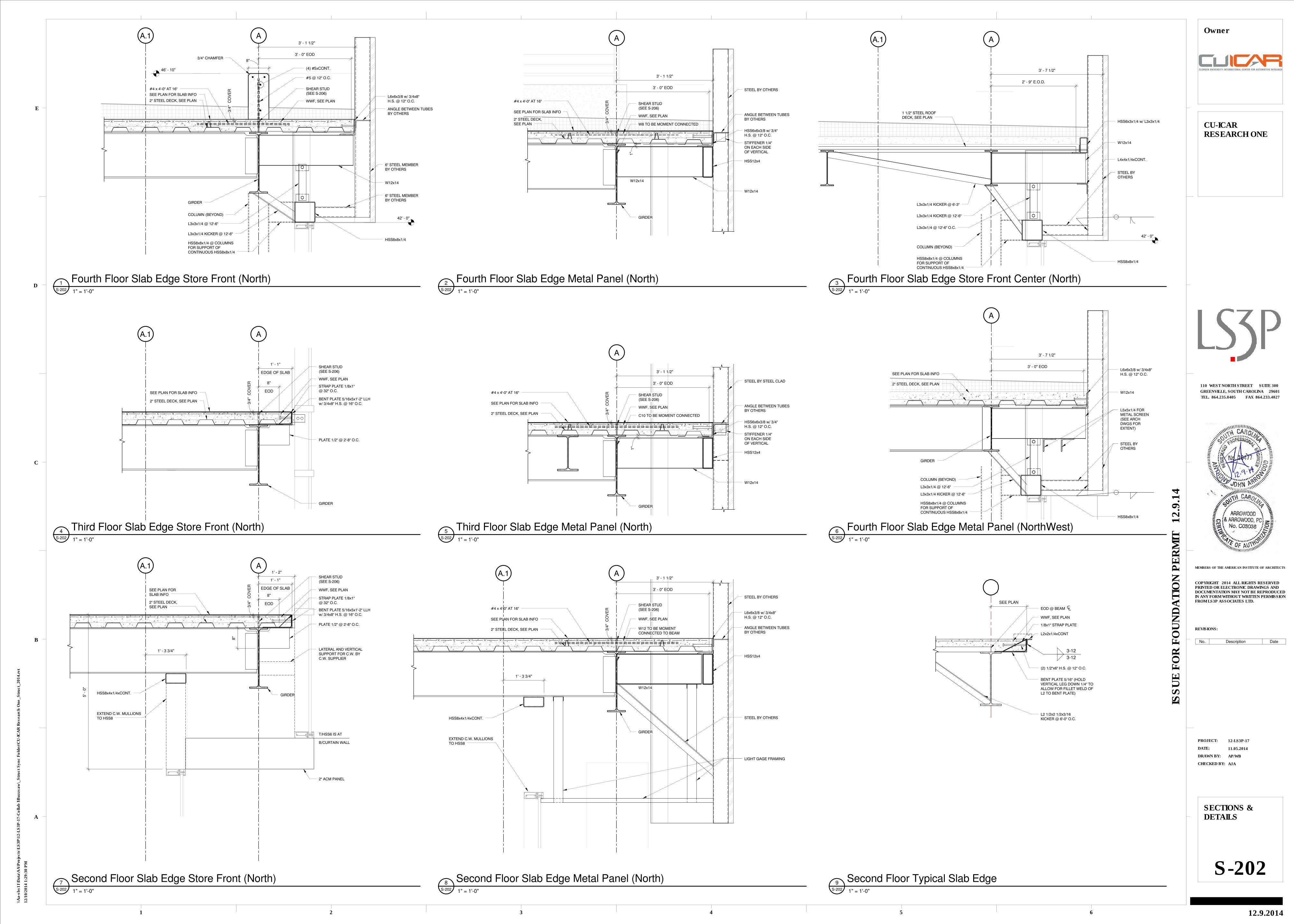
A
3/4
" C
OV
ER
SEE PLAN FORSLAB INFO
2" STEEL DECK,SEE PLAN
EDGE OF SLAB
1' - 1"
BENT PLATE 5/16x5x1'-2" LLHw/ 3/4x8" H.S. @ 16" O.C.
GIRDER
SHEAR STUD(SEE S-206)
WWF, SEE PLAN
5' -
0"
STRAP PLATE 1/8x1"@ 32" O.C.
LATERAL AND VERTICALSUPPORT FOR C.W. BYC.W. SUPPLIER
2" ACM PANEL
T/HSS6 IS AT
B/CURTAIN WALL
HSS8x4x1/4xCONT.
EXTEND C.W. MULLIONSTO HSS8
A.11' - 2"
1' - 3 3/4"
PLATE 1/2" @ 2'-8" O.C.
8"
EOD
8"
A
3/4
" C
OV
ER
SEE PLAN FOR SLAB INFO
2" STEEL DECK, SEE PLAN
EDGE OF SLAB
1' - 1"
GIRDER
SHEAR STUD(SEE S-206)
WWF, SEE PLAN
A.1
BENT PLATE 5/16x5x1'-2" LLHw/ 3/4x8" H.S. @ 16" O.C.
STRAP PLATE 1/8x1"@ 32" O.C.
PLATE 1/2" @ 2'-8" O.C.
EOD
8"
A
3/4
" C
OV
ER
SEE PLAN FOR SLAB INFO
2" STEEL DECK, SEE PLAN
#4 x 4'-0" AT 16" SHEAR STUD(SEE S-206)
WWF, SEE PLAN
COLUMN (BEYOND)
6" STEEL MEMBERBY OTHERS
HSS8x8x1/4
W12x14
L3x3x1/4 KICKER @ 12'-6"
#5 @ 12" O.C.
(4) #5xCONT.46' - 10"
3' - 1 1/2"
3/4" CHAMFER8"
L3x3x1/4 @ 12'-6"
L6x6x3/8 w/ 3/4x8"H.S. @ 12" O.C.
ANGLE BETWEEN TUBESBY OTHERS
6" STEEL MEMBERBY OTHERS
42' - 0"
A.1
3' - 0" EOD
HSS8x8x1/4 @ COLUMNSFOR SUPPORT OFCONTINUOUS HSS8x8x1/4
GIRDER
A
3/4
" C
OV
ER
SEE PLAN FOR SLAB INFO
2" STEEL DECK, SEE PLAN
#4 x 4'-0" AT 16"
STEEL BY OTHERS
GIRDER
W12x14
SHEAR STUD(SEE S-206)
WWF, SEE PLAN
W12 TO BE MOMENTCONNECTED TO BEAM
L6x6x3/8 w/ 3/4x8"H.S. @ 12" O.C.
ANGLE BETWEEN TUBESBY OTHERS
STEEL BY OTHERSHSS8x4x1/4xCONT.
EXTEND C.W. MULLIONSTO HSS8
LIGHT GAGE FRAMING
A.1
HSS12x4
3' - 1 1/2"
3' - 0" EOD
1' - 3 3/4"
A
3/4
" C
OV
ER
SEE PLAN FOR SLAB INFO
2" STEEL DECK, SEE PLAN
#4 x 4'-0" AT 16"
GIRDER
HSS6x6x3/8 w/ 3/4"H.S. @ 12" O.C.
STEEL BY STEEL CLAD
STIFFENER 1/4"ON EACH SIDEOF VERTICAL
SHEAR STUD(SEE S-206)
WWF, SEE PLAN
C10 TO BE MOMENT CONNECTED
HSS12x4
3' - 1 1/2"
W12x14
1"
3' - 0" EOD
ANGLE BETWEEN TUBESBY OTHERS
A
3/4
" C
OV
ER SHEAR STUD
(SEE S-206)
WWF, SEE PLANSEE PLAN FOR SLAB INFO
2" STEEL DECK,SEE PLAN
#4 x 4'-0" AT 16"
GIRDER
STEEL BY OTHERS
3' - 1 1/2"
W8 TO BE MOMENT CONNECTED
W12x14
HSS6x6x3/8 w/ 3/4"H.S. @ 12" O.C.
STIFFENER 1/4"ON EACH SIDEOF VERTICAL
HSS12x4
W12x14
ANGLE BETWEEN TUBESBY OTHERS
3' - 0" EOD
1"
A
1 1/2" STEEL ROOFDECK, SEE PLAN
3' - 7 1/2"
STEEL BYOTHERS
HSS8x8x1/4
L4x4x1/4xCONT.
L3x3x1/4 @ 12'-6" O.C.
W12x14
2' - 9" E.O.D.
L3x3x1/4 KICKER @ 6'-3"
A.1
HSS8x8x1/4 @ COLUMNSFOR SUPPORT OFCONTINUOUS HSS8x8x1/4
COLUMN (BEYOND)
42' - 0"
L3x3x1/4 KICKER @ 12'-6"
HSS6x3x1/4 w/ L3x3x1/4
A
3' - 7 1/2"
GIRDER
L5x5x1/4 FORMETAL SCREEN(SEE ARCHDWGS FOREXTENT)
HSS8x8x1/4
STEEL BYOTHERS
SEE PLAN FOR SLAB INFO
2" STEEL DECK, SEE PLAN
COLUMN (BEYOND)
W12x14
L3x3x1/4 KICKER @ 12'-6"
L3x3x1/4 @ 12'-6"
L6x6x3/8 w/ 3/4x8"H.S. @ 12" O.C.
HSS8x8x1/4 @ COLUMNSFOR SUPPORT OFCONTINUOUS HSS8x8x1/4
3' - 0" EOD
BENT PLATE 5/16" (HOLDVERTICAL LEG DOWN 1/4" TOALLOW FOR FILLET WELD OFL2 TO BENT PLATE)
WWF, SEE PLAN
L2 1/2x2 1/2x3/16KICKER @ 6'-0" O.C.
(2) 1/2"x6" H.S. @ 12" O.C.
EOD @ BEAM
SEE PLAN
1/8x1" STRAP PLATE
L2x2x1/4xCONT
3-12
3-12
CHECKED BY:
DRAWN BY:
DATE:
PROJECT:
REVISIONS:
MEMBERS OF THE AMERICAN INSTITUTE OF ARCHITECTS
1
A
2 3 4 5 6
B
C
D
E
COPYRIGHT 2014 ALL RIGHTS RESERVEDPRINTED OR ELECTRONIC DRAWINGS ANDDOCUMENTATION MAY NOT BE REPRODUCEDIN ANY FORM WITHOUT WRITTEN PERMISSIONFROM LS3P ASSOCIATES LTD.
TEL. 864.235.0405 FAX 864.233.4027
GREENVILLE, SOUTH CAROLINA 29601
110 WEST NORTH STREET SUITE 300
ISS
UE
FO
R F
OU
ND
AT
ION
PE
RM
IT 1
2.9
.14
12/1
0/2
014 1
:29:3
0 P
M
\\A
a-s
bs11\D
ata
\AA
\Pro
jects
\LS
3P
\12-L
S3P
-17-C
ollab
I\B
uzzsaw
\_S
tru
ct
Syn
c F
old
er\
CU
-IC
AR
Researc
h O
ne_S
tru
ct_
2014.r
vt
12-LS3P-17
11.05.2014
AP/WB
AJA
SECTIONS &DETAILS
S-202
CU-ICARRESEARCH ONE
12.9.2014
Owner
1" = 1'-0"S-202
7 Second Floor Slab Edge Store Front (North)
1" = 1'-0"S-202
4 Third Floor Slab Edge Store Front (North)
1" = 1'-0"S-202
1 Fourth Floor Slab Edge Store Front (North)
1" = 1'-0"S-202
8 Second Floor Slab Edge Metal Panel (North)
1" = 1'-0"S-202
5 Third Floor Slab Edge Metal Panel (North)
1" = 1'-0"S-202
2 Fourth Floor Slab Edge Metal Panel (North) 1" = 1'-0"S-202
3 Fourth Floor Slab Edge Store Front Center (North)
1" = 1'-0"S-202
6 Fourth Floor Slab Edge Metal Panel (NorthWest)
1" = 1'-0"S-202
9 Second Floor Typical Slab Edge
No. Description Date
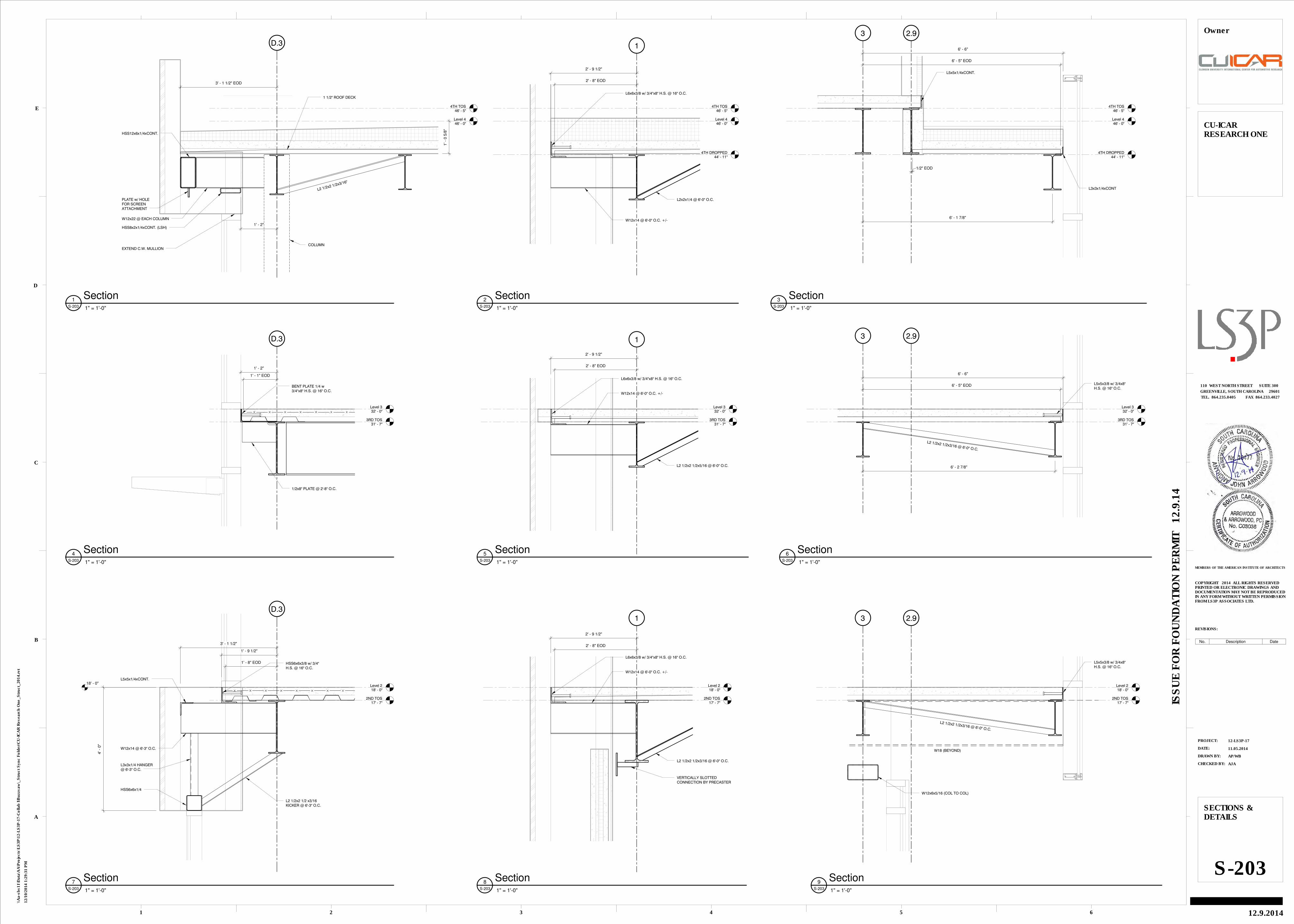
Level 218' - 0"
2ND TOS17' - 7"
D.3
W12x14 @ 6'-3" O.C.
HSS6x6x1/4
L3x3x1/4 HANGER@ 6'-3" O.C.
L2 1/2x2 1/2 x3/16KICKER @ 6'-3" O.C.
L5x5x1/4xCONT.18' - 0"
4' -
0"
3' - 1 1/2"
HSS6x6x3/8 w/ 3/4"H.S. @ 16" O.C.
1' - 9 1/2"
1' - 8" EOD
Level 446' - 0"
4TH TOS46' - 5"
D.3
HSS8x2x1/4xCONT. (LSH)
HSS12x6x1/4xCONT.
EXTEND C.W. MULLION
W12x22 @ EACH COLUMN
PLATE w/ HOLEFOR SCREENATTACHMENT
3' - 1 1/2" EOD
1' -
0 5
/8"
L2 1/2x2 1/2x3/16"
1 1/2" ROOF DECK
COLUMN
1' - 2"
Level 332' - 0"
3RD TOS31' - 7"
D.3
BENT PLATE 1/4 w3/4"x8" H.S. @ 16" O.C.
1/2x8" PLATE @ 2'-8" O.C.
1' - 2"
1' - 1" EOD
Level 218' - 0"
1
2ND TOS17' - 7"
W12x14 @ 6'-0" O.C. +/-
L6x6x3/8 w/ 3/4"x8" H.S. @ 16" O.C.
L2 1/2x2 1/2x3/16 @ 6'-0" O.C.
VERTICALLY SLOTTEDCONNECTION BY PRECASTER
2' - 9 1/2"
2' - 8" EOD
Level 332' - 0"
1
3RD TOS31' - 7"
W12x14 @ 6'-0" O.C. +/-
L6x6x3/8 w/ 3/4"x8" H.S. @ 16" O.C.
L2 1/2x2 1/2x5/16 @ 6'-0" O.C.
2' - 9 1/2"
2' - 8" EOD
Level 446' - 0"
1
4TH TOS46' - 5"
4TH DROPPED44' - 11"
W12x14 @ 6'-0" O.C. +/-
L6x6x3/8 w/ 3/4"x8" H.S. @ 16" O.C.
L2x2x1/4 @ 6'-0" O.C.
2' - 9 1/2"
2' - 8" EOD
Level 218' - 0"
3
2ND TOS17' - 7"
2.9
W18 (BEYOND)
L2 1/2x2 1/2x3/16 @ 6'-0" O.C.
L5x5x3/8 w/ 3/4x8"H.S. @ 16" O.C.
W12x6x5/16 (COL TO COL)
Level 332' - 0"
3
3RD TOS31' - 7"
2.9
L5x5x3/8 w/ 3/4x8"H.S. @ 16" O.C.
6' - 6"
6' - 5" EOD
6' - 2 7/8"
L2 1/2x2 1/2x3/16 @ 6'-0" O.C.
Level 446' - 0"
3
4TH TOS46' - 5"
2.9
4TH DROPPED44' - 11"
L3x3x1/4xCONT
L5x5x1/4xCONT.
6' - 1 7/8"
6' - 6"
6' - 5" EOD
1/2" EOD
CHECKED BY:
DRAWN BY:
DATE:
PROJECT:
REVISIONS:
MEMBERS OF THE AMERICAN INSTITUTE OF ARCHITECTS
1
A
2 3 4 5 6
B
C
D
E
COPYRIGHT 2014 ALL RIGHTS RESERVEDPRINTED OR ELECTRONIC DRAWINGS ANDDOCUMENTATION MAY NOT BE REPRODUCEDIN ANY FORM WITHOUT WRITTEN PERMISSIONFROM LS3P ASSOCIATES LTD.
TEL. 864.235.0405 FAX 864.233.4027
GREENVILLE, SOUTH CAROLINA 29601
110 WEST NORTH STREET SUITE 300
ISS
UE
FO
R F
OU
ND
AT
ION
PE
RM
IT 1
2.9
.14
12/1
0/2
014 1
:29:3
1 P
M
\\A
a-s
bs11\D
ata
\AA
\Pro
jects
\LS
3P
\12-L
S3P
-17-C
ollab
I\B
uzzsaw
\_S
tru
ct
Syn
c F
old
er\
CU
-IC
AR
Researc
h O
ne_S
tru
ct_
2014.r
vt
12-LS3P-17
11.05.2014
AP/WB
AJA
SECTIONS &DETAILS
S-203
CU-ICARRESEARCH ONE
12.9.2014
Owner
1" = 1'-0"S-203
7 Section
1" = 1'-0"S-203
1 Section
1" = 1'-0"S-203
4 Section
1" = 1'-0"S-203
8 Section
1" = 1'-0"S-203
5 Section
1" = 1'-0"S-203
2 Section
1" = 1'-0"S-203
9 Section
1" = 1'-0"S-203
6 Section
1" = 1'-0"S-203
3 Section
No. Description Date
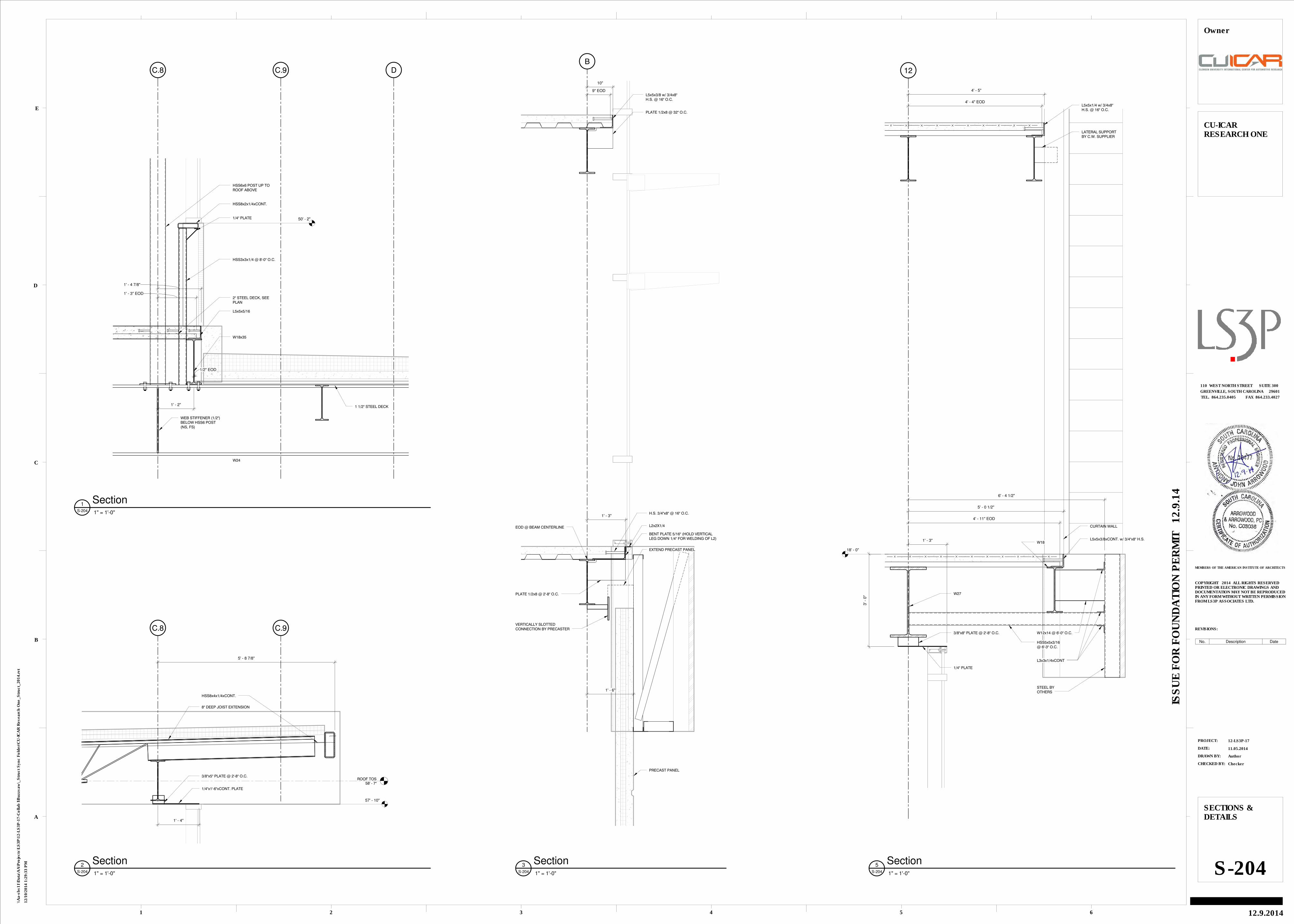
C.9 DC.8
W18x35
W24
1 1/2" STEEL DECK
2" STEEL DECK, SEEPLAN
HSS3x3x1/4 @ 8'-0" O.C.
HSS6x6 POST UP TOROOF ABOVE
HSS8x2x1/4xCONT.
L5x5x5/16
WEB STIFFENER (1/2")BELOW HSS6 POST(NS, FS)
1' - 2"
1/4" PLATE 50' - 2"
1/2" EOD
1' - 4 7/8"
1' - 3" EOD
C.9
ROOF TOS58' - 7"
C.8
5' - 8 7/8"
3/8"x5" PLATE @ 2'-8" O.C.
1/4"x1'-6"xCONT. PLATE
HSS8x4x1/4xCONT.
8" DEEP JOIST EXTENSION
1' - 4"
57' - 10"
B
1' - 6"
PRECAST PANEL
VERTICALLY SLOTTEDCONNECTION BY PRECASTER
L2x2X1/4
BENT PLATE 5/16" (HOLD VERTICALLEG DOWN 1/4" FOR WELDING OF L2)
EXTEND PRECAST PANEL
PLATE 1/2x8 @ 32" O.C.
L5x5x3/8 w/ 3/4x8"H.S. @ 16" O.C.
10"
9" EOD
H.S. 3/4"x8" @ 16" O.C.
PLATE 1/2x8 @ 2'-8" O.C.
1' - 3"
EOD @ BEAM CENTERLINE
12
CURTAIN WALL
L5x5x1/4 w/ 3/4x8"H.S. @ 16" O.C.
LATERAL SUPPORTBY C.W. SUPPLIER
W18
W27
1' - 3"
HSS5x5x3/16@ 6'-3" O.C.
STEEL BYOTHERS
1/4" PLATE
3/8"x8" PLATE @ 2'-8" O.C.
L5x5x3/8xCONT. w/ 3/4"x8" H.S.
L3x3x1/4xCONT
18' - 0"
3' -
0"
W12x14 @ 6'-0" O.C.
4' - 11" EOD
4' - 4" EOD
4' - 5"
5' - 0 1/2"
6' - 4 1/2"
CHECKED BY:
DRAWN BY:
DATE:
PROJECT:
REVISIONS:
MEMBERS OF THE AMERICAN INSTITUTE OF ARCHITECTS
1
A
2 3 4 5 6
B
C
D
E
COPYRIGHT 2014 ALL RIGHTS RESERVEDPRINTED OR ELECTRONIC DRAWINGS ANDDOCUMENTATION MAY NOT BE REPRODUCEDIN ANY FORM WITHOUT WRITTEN PERMISSIONFROM LS3P ASSOCIATES LTD.
TEL. 864.235.0405 FAX 864.233.4027
GREENVILLE, SOUTH CAROLINA 29601
110 WEST NORTH STREET SUITE 300
ISS
UE
FO
R F
OU
ND
AT
ION
PE
RM
IT 1
2.9
.14
12/1
0/2
014 1
:29:3
3 P
M
\\A
a-s
bs11\D
ata
\AA
\Pro
jects
\LS
3P
\12-L
S3P
-17-C
ollab
I\B
uzzsaw
\_S
tru
ct
Syn
c F
old
er\
CU
-IC
AR
Researc
h O
ne_S
tru
ct_
2014.r
vt
12-LS3P-17
11.05.2014
Author
Checker
SECTIONS &DETAILS
S-204
CU-ICARRESEARCH ONE
12.9.2014
Owner
1" = 1'-0"S-204
1 Section
1" = 1'-0"S-204
2 Section 1" = 1'-0"S-204
3 Section 1" = 1'-0"S-204
5 Section
No. Description Date
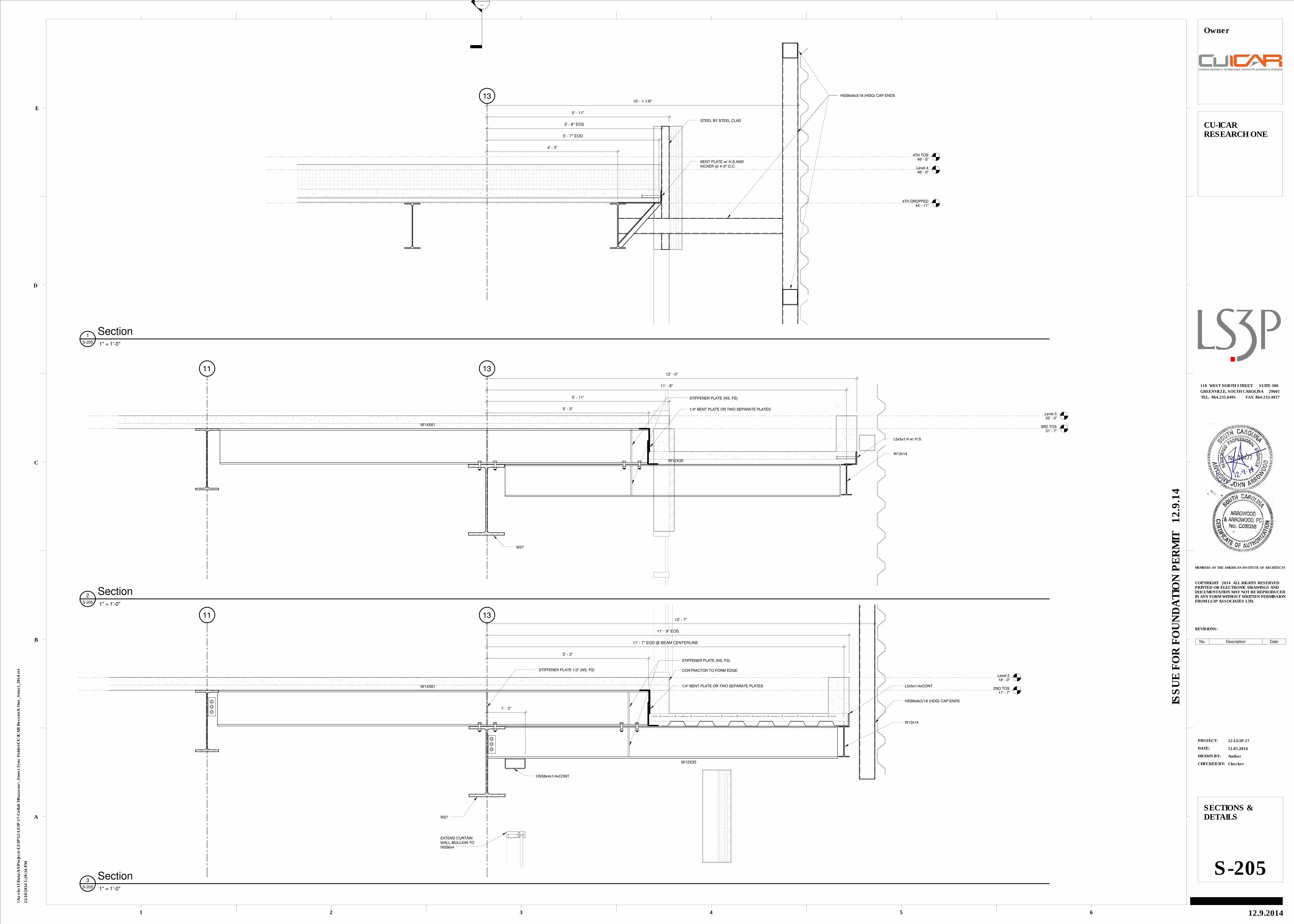
Level 218' - 0"
11
2ND TOS17' - 7"
13
HSS6x6x3/16 (HDG) CAP ENDS
W12X35
W14X61
W27
W12x14
STIFFENER PLATE (NS, FS)
EXTEND CURTAINWALL MULLION TOHSS6x4
HSS8x4x1/4xCONT
1/4" BENT PLATE OR TWO SEPARATE PLATES
STIFFENER PLATE 1/2" (NS, FS)
1' - 3"
5' - 3"
CONTRACTOR TO FORM EDGE
L5x5x1/4xCONT
12' - 7"
11' - 9" EOS
11' - 7" EOD @ BEAM CENTERLINE
Level 332' - 0"
11
3RD TOS31' - 7"
13
L5x5x1/4 w/ H.S.
W12x14
W14X61
W27
STIFFENER PLATE (NS, FS)
W12X35
1/4" BENT PLATE OR TWO SEPARATE PLATES
12' - 0"
11' - 8"
5' - 11"
5' - 3"
Level 446' - 0"
4TH TOS46' - 5"
4TH DROPPED44' - 11"
13 HSS6x6x3/16 (HDG) CAP ENDS
STEEL BY STEEL CLAD
BENT PLATE w/ H.S.ANDKICKER @ 4'-0" O.C.
10' - 1 1/8"
5' - 11"
5' - 8" EOS
5' - 7" EOD
4' - 3"
-
---
CHECKED BY:
DRAWN BY:
DATE:
PROJECT:
REVISIONS:
MEMBERS OF THE AMERICAN INSTITUTE OF ARCHITECTS
1
A
2 3 4 5 6
B
C
D
E
COPYRIGHT 2014 ALL RIGHTS RESERVEDPRINTED OR ELECTRONIC DRAWINGS ANDDOCUMENTATION MAY NOT BE REPRODUCEDIN ANY FORM WITHOUT WRITTEN PERMISSIONFROM LS3P ASSOCIATES LTD.
TEL. 864.235.0405 FAX 864.233.4027
GREENVILLE, SOUTH CAROLINA 29601
110 WEST NORTH STREET SUITE 300
ISS
UE
FO
R F
OU
ND
AT
ION
PE
RM
IT 1
2.9
.14
12/1
0/2
014 1
:29:3
4 P
M
\\A
a-s
bs11\D
ata
\AA
\Pro
jects
\LS
3P
\12-L
S3P
-17-C
ollab
I\B
uzzsaw
\_S
tru
ct
Syn
c F
old
er\
CU
-IC
AR
Researc
h O
ne_S
tru
ct_
2014.r
vt
12-LS3P-17
11.05.2014
Author
Checker
SECTIONS &DETAILS
S-205
CU-ICARRESEARCH ONE
12.9.2014
Owner
1" = 1'-0"S-205
3 Section
1" = 1'-0"S-205
2 Section
1" = 1'-0"S-205
1 Section
No. Description Date
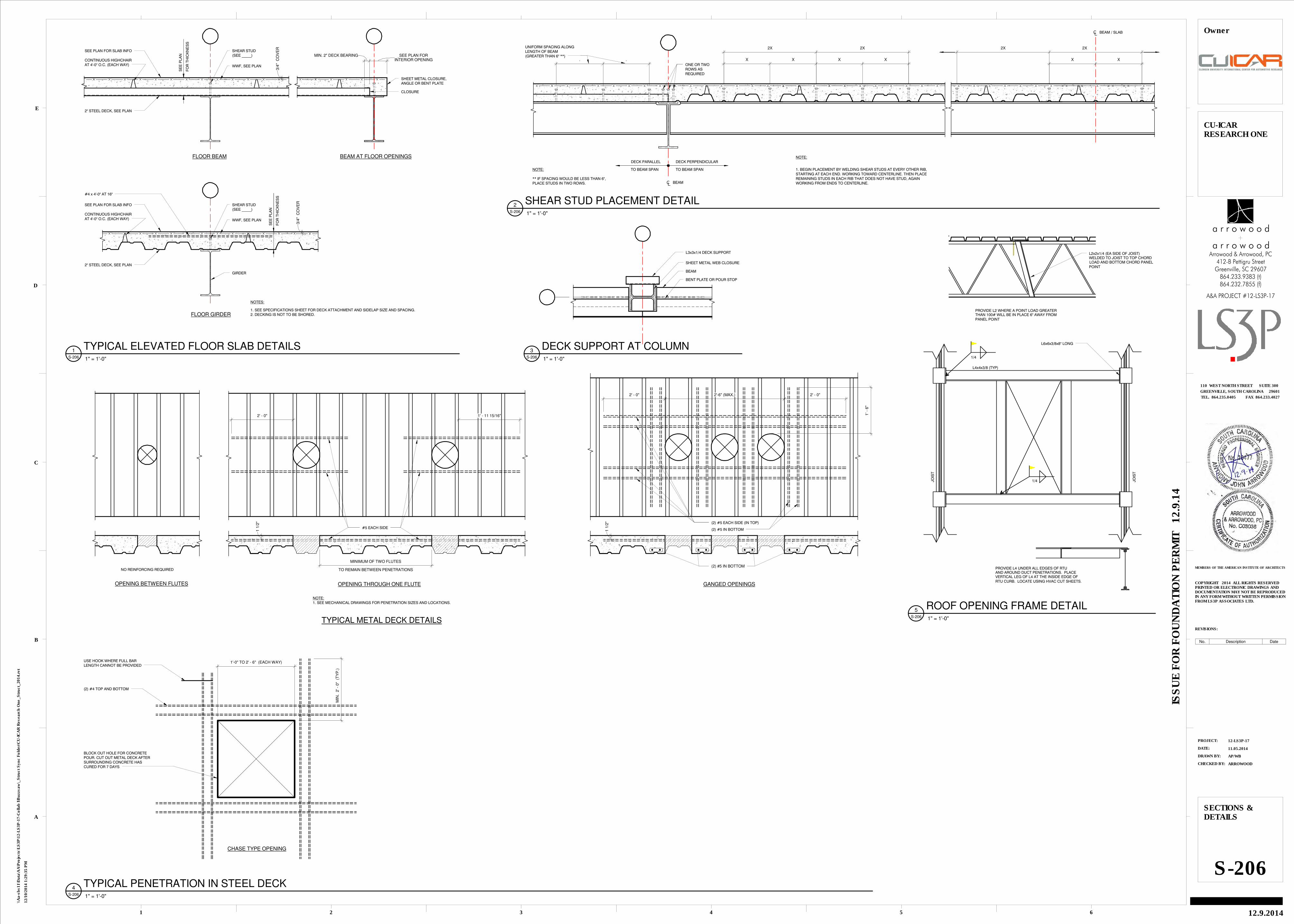
MIN. 2" DECK BEARINGINTERIOR OPENING
SEE PLAN FOR
BEAM AT FLOOR OPENINGSFLOOR BEAM
3/4
" C
OV
ER
SHEAR STUD(SEE _____)
WWF, SEE PLAN
SEE PLAN FOR SLAB INFO
CONTINUOUS HIGHCHAIRAT 4'-0" O.C. (EACH WAY)
2" STEEL DECK, SEE PLAN
SE
E P
LA
N
FO
R T
HIC
KN
ES
S
SHEET METAL CLOSURE,ANGLE OR BENT PLATE
CLOSURE
FLOOR GIRDER
3/4
" C
OV
ER
SHEAR STUD(SEE _____)
WWF, SEE PLAN
SEE PLAN FOR SLAB INFO
CONTINUOUS HIGHCHAIRAT 4'-0" O.C. (EACH WAY)
2" STEEL DECK, SEE PLAN
SE
E P
LA
N
FO
R T
HIC
KN
ES
S
#4 x 4'-0" AT 16"
GIRDER
NOTES:
1. SEE SPECIFICATIONS SHEET FOR DECK ATTACHMENT AND SIDELAP SIZE AND SPACING.2. DECKING IS NOT TO BE SHORED.
ONE OR TWOROWS ASREQUIRED
NOTE:
1. BEGIN PLACEMENT BY WELDING SHEAR STUDS AT EVERY OTHER RIB,STARTING AT EACH END. WORKING TOWARD CENTERLINE. THEN PLACEREMAINING STUDS IN EACH RIB THAT DOES NOT HAVE STUD, AGAINWORKING FROM ENDS TO CENTERLINE.
NOTE:
** IF SPACING WOULD BE LESS THAN 6",PLACE STUDS IN TWO ROWS.
DECK PERPENDICULARDECK PARALLEL
TO BEAM SPANTO BEAM SPAN
BEAM
BEAM / SLAB
X X
2X 2X
X X X X
2X 2X
. .
UNIFORM SPACING ALONGLENGTH OF BEAM(GREATER THAN 6" **)
L3x3x1/4 DECK SUPPORT
SHEET METAL WEB CLOSURE
BEAM
BENT PLATE OR POUR STOP
CHASE TYPE OPENING
USE HOOK WHERE FULL BARLENGTH CANNOT BE PROVIDED
(2) #4 TOP AND BOTTOM
BLOCK OUT HOLE FOR CONCRETEPOUR. CUT OUT METAL DECK AFTERSURROUNDING CONCRETE HASCURED FOR 7 DAYS
MIN
. 2
' - 0
" (
TY
P.)
1'-0" TO 2' - 6" (EACH WAY)
NO REINFORCING REQUIRED
OPENING BETWEEN FLUTES
TYPICAL METAL DECK DETAILS
OPENING THROUGH ONE FLUTE
NOTE:1. SEE MECHANICAL DRAWINGS FOR PENETRATION SIZES AND LOCATIONS.
2' - 0" 1' - 11 15/16"
#5 EACH SIDE
1 1
/2"
TO REMAIN BETWEEN PENETRATIONS
MINIMUM OF TWO FLUTES
GANGED OPENINGS
(2) #5 EACH SIDE (IN TOP)
1 1
/2"
(2) #5 IN BOTTOM
(2) #5 IN BOTTOM
2' - 0" 2' - 0"2'-6" (MAX.)
1' -
6"
L4x4x3/8 (TYP)
JO
IST
1/4
1/4
PROVIDE L4 UNDER ALL EDGES OF RTUAND AROUND DUCT PENETRATIONS. PLACEVERTICAL LEG OF L4 AT THE INSIDE EDGE OFRTU CURB. LOCATE USING HVAC CUT SHEETS.
L6x6x3/8x8" LONG
JO
IST
LOAD AND BOTTOM CHORD PANELWELDED TO JOIST TO TOP CHORDL2x2x1/4 (EA SIDE OF JOIST)
POINT
PROVIDE L2 WHERE A POINT LOAD GREATERTHAN 100# WILL BE IN PLACE 6" AWAY FROMPANEL POINT
CHECKED BY:
DRAWN BY:
DATE:
PROJECT:
REVISIONS:
MEMBERS OF THE AMERICAN INSTITUTE OF ARCHITECTS
1
A
2 3 4 5 6
B
C
D
E
COPYRIGHT 2014 ALL RIGHTS RESERVEDPRINTED OR ELECTRONIC DRAWINGS ANDDOCUMENTATION MAY NOT BE REPRODUCEDIN ANY FORM WITHOUT WRITTEN PERMISSIONFROM LS3P ASSOCIATES LTD.
TEL. 864.235.0405 FAX 864.233.4027
GREENVILLE, SOUTH CAROLINA 29601
110 WEST NORTH STREET SUITE 300
ISS
UE
FO
R F
OU
ND
AT
ION
PE
RM
IT 1
2.9
.14
12/1
0/2
014 1
:29:3
5 P
M
\\A
a-s
bs11\D
ata
\AA
\Pro
jects
\LS
3P
\12-L
S3P
-17-C
ollab
I\B
uzzsaw
\_S
tru
ct
Syn
c F
old
er\
CU
-IC
AR
Researc
h O
ne_S
tru
ct_
2014.r
vt
12-LS3P-17
11.05.2014
AP/WB
ARROWOOD
SECTIONS &DETAILS
S-206
CU-ICARRESEARCH ONE
12.9.2014
Owner
1" = 1'-0"S-206
1 TYPICAL ELEVATED FLOOR SLAB DETAILS
1" = 1'-0"S-206
2 SHEAR STUD PLACEMENT DETAIL
1" = 1'-0"S-206
3 DECK SUPPORT AT COLUMN
1" = 1'-0"S-206
4 TYPICAL PENETRATION IN STEEL DECK
1" = 1'-0"S-206
5 ROOF OPENING FRAME DETAIL
864.232.7855 (f)864.233.9383 (t)
Greenville, SC 29607412-B Pettigru Street
Arrowood & Arrowood, PC
A&A PROJECT #12-LS3P-17
a r r o w o o d
a r r o w o o d
No. Description Date
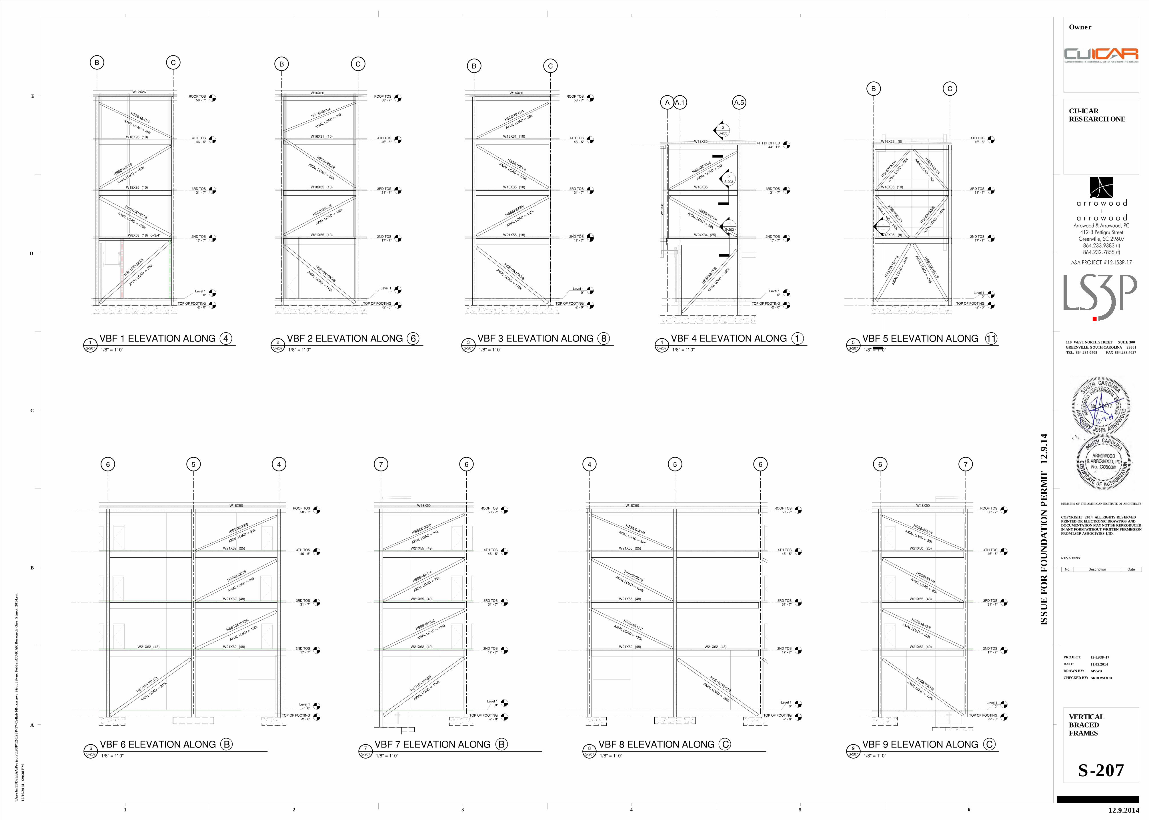
Level 10"
B C
TOP OF FOOTING-2' - 0"
2ND TOS17' - 7"
3RD TOS31' - 7"
4TH TOS46' - 5"
ROOF TOS58' - 7"
W12X26
W16X26 (10)
W18X35 (10)
W8X58 c=3/4"(18)
HSS10X10
X3/8
HSS10X10X3/8
HSS8X8X5/8
HSS6X6X1/4
AXIAL
LOAD =
200
k
AXIAL LOAD = 175k
AXIAL LOAD = 160k
AXIAL LOAD = 30k
Level 10"
B C
TOP OF FOOTING-2' - 0"
2ND TOS17' - 7"
3RD TOS31' - 7"
4TH TOS46' - 5"
ROOF TOS58' - 7"
W16X26
W16X31 (10)
W18X35 (10)
W21X55 (18)
HSS10X10X3/8
HSS8X8X3/8
HSS8X8X3/8
HSS6X6X1/4
AXIAL LOAD =
175k
AXIAL LOAD = 155k
AXIAL LOAD = 95k
AXIAL LOAD = 20k
Level 10"
Level 218' - 0"
B C
TOP OF FOOTING-2' - 0"
2ND TOS17' - 7"
3RD TOS31' - 7"
4TH TOS46' - 5"
ROOF TOS58' - 7"
W16X26
HSS6X6X1/4
W16X31 (10)
HSS8X8X1/4
W18X35 (10)
HSS8X8X3/8
W21X55 (18)
HSS10X10X3/8
AXIAL LOAD =
170k
AXIAL LOAD = 135k
AXIAL LOAD = 105k
AXIAL LOAD = 35k
Level 10"
A
TOP OF FOOTING-2' - 0"
2ND TOS17' - 7"
3RD TOS31' - 7"
A.5
W18X35
HSS6X6X1/4
W18X35
HSS8X8X1/4
W24X84 (25)
HSS8X
8X1/
2
W1
0X
49
4TH DROPPED44' - 11"
AXIAL LOAD = 33k
AXIAL LOAD = 92k
AXIAL
LOAD
= 1
68k
A.1
8
S-203
5
S-203
2
S-203
Level 10"
B C
TOP OF FOOTING-2' - 0"
2ND TOS17' - 7"
3RD TOS31' - 7"
4TH TOS46' - 5"
HSS6X
6X1/4
HSS8X
8X3/8
HSS8X
8X3/
8
HSS
10X
10X
3/8 H
SS
10X10X
3/8
W18X35 (8)
W18X35 (10)
W16X26 (8)
HSS6X
6X1/
4A
XIA
L LO
AD
= 2
50k
AXIAL LO
AD =
140k
AXI
AL
LOAD
= 8
0k
AXIA
L LO
AD =
140
k
AXIAL LO
AD =
80k
AXIA
L LOA
D =
250k
-
---
Level 10"
456
TOP OF FOOTING-2' - 0"
2ND TOS17' - 7"
3RD TOS31' - 7"
4TH TOS46' - 5"
ROOF TOS58' - 7"
HSS10X10X1/2
AXIAL LOAD =
210k
HSS10X10X3/8
AXIAL LOAD = 150k
HSS8X8X3/8
AXIAL LOAD = 90k
HSS6X6X3/8
AXIAL LOAD = 35k
W21X62 (48) W21X62 (48)
W21X62 (48)
W21X62 (25)
W18X50
Level 10"
67
TOP OF FOOTING-2' - 0"
2ND TOS17' - 7"
3RD TOS31' - 7"
4TH TOS46' - 5"
ROOF TOS58' - 7"
HSS6X6X3/8
HSS8X8X1/4
HSS8X8X1/2
HSS10X10X3/8
AXIAL LOAD = 75k
AXIAL LOAD = 125k
AXIAL LOAD =
150k
AXIAL LOAD = 35k
W21X62 (49)
W21X55 (49)
W21X55 (49)
W18X50
Level 10"
4 5 6
TOP OF FOOTING-2' - 0"
2ND TOS17' - 7"
3RD TOS31' - 7"
4TH TOS46' - 5"
ROOF TOS58' - 7"
HSS8X8X1/2
HSS10X10X3/8
AXIAL LOAD = 130k
AXIAL LOAD = 165k
HSS8X8X3/8AXIAL LOAD = 100k
HSS6X6X1/4AXIAL LOAD = 30k
W21X55 (25)
W21X55 (48)
W21X62 (48) W21X62 (48)
W18X50
Level 10"
6 7
TOP OF FOOTING-2' - 0"
2ND TOS17' - 7"
3RD TOS31' - 7"
4TH TOS46' - 5"
ROOF TOS58' - 7"
HSS6X6X1/4
HSS8X8X1/4
HSS8X8X3/8
HSS8X8X1/2
AXIAL LOAD = 30k
AXIAL LOAD = 105k
AXIAL LOAD = 120k
AXIAL LOAD = 80k
W18X50
W21X50 (25)
W21X55 (48)
W21X62 (49)
CHECKED BY:
DRAWN BY:
DATE:
PROJECT:
REVISIONS:
MEMBERS OF THE AMERICAN INSTITUTE OF ARCHITECTS
1
A
2 3 4 5 6
B
C
D
E
COPYRIGHT 2014 ALL RIGHTS RESERVEDPRINTED OR ELECTRONIC DRAWINGS ANDDOCUMENTATION MAY NOT BE REPRODUCEDIN ANY FORM WITHOUT WRITTEN PERMISSIONFROM LS3P ASSOCIATES LTD.
TEL. 864.235.0405 FAX 864.233.4027
GREENVILLE, SOUTH CAROLINA 29601
110 WEST NORTH STREET SUITE 300
ISS
UE
FO
R F
OU
ND
AT
ION
PE
RM
IT 1
2.9
.14
12/1
0/2
014 1
:29:3
8 P
M
\\A
a-s
bs11\D
ata
\AA
\Pro
jects
\LS
3P
\12-L
S3P
-17-C
ollab
I\B
uzzsaw
\_S
tru
ct
Syn
c F
old
er\
CU
-IC
AR
Researc
h O
ne_S
tru
ct_
2014.r
vt
12-LS3P-17
11.05.2014
AP/WB
ARROWOOD
VERTICALBRACEDFRAMES
S-207
CU-ICARRESEARCH ONE
12.9.2014
Owner
1/8" = 1'-0"S-207
1 VBF 1 ELEVATION ALONG 4 1/8" = 1'-0"S-207
2 VBF 2 ELEVATION ALONG 6 1/8" = 1'-0"S-207
3 VBF 3 ELEVATION ALONG 8 1/8" = 1'-0"S-207
4 VBF 4 ELEVATION ALONG 1 1/8" = 1'-0"S-207
5 VBF 5 ELEVATION ALONG 11
864.232.7855 (f)864.233.9383 (t)
Greenville, SC 29607412-B Pettigru Street
Arrowood & Arrowood, PC
A&A PROJECT #12-LS3P-17
a r r o w o o d
a r r o w o o d
1/8" = 1'-0"S-207
6 VBF 6 ELEVATION ALONG B 1/8" = 1'-0"S-207
7 VBF 7 ELEVATION ALONG B 1/8" = 1'-0"S-207
8 VBF 8 ELEVATION ALONG C 1/8" = 1'-0"S-207
9 VBF 9 ELEVATION ALONG C
No. Description Date
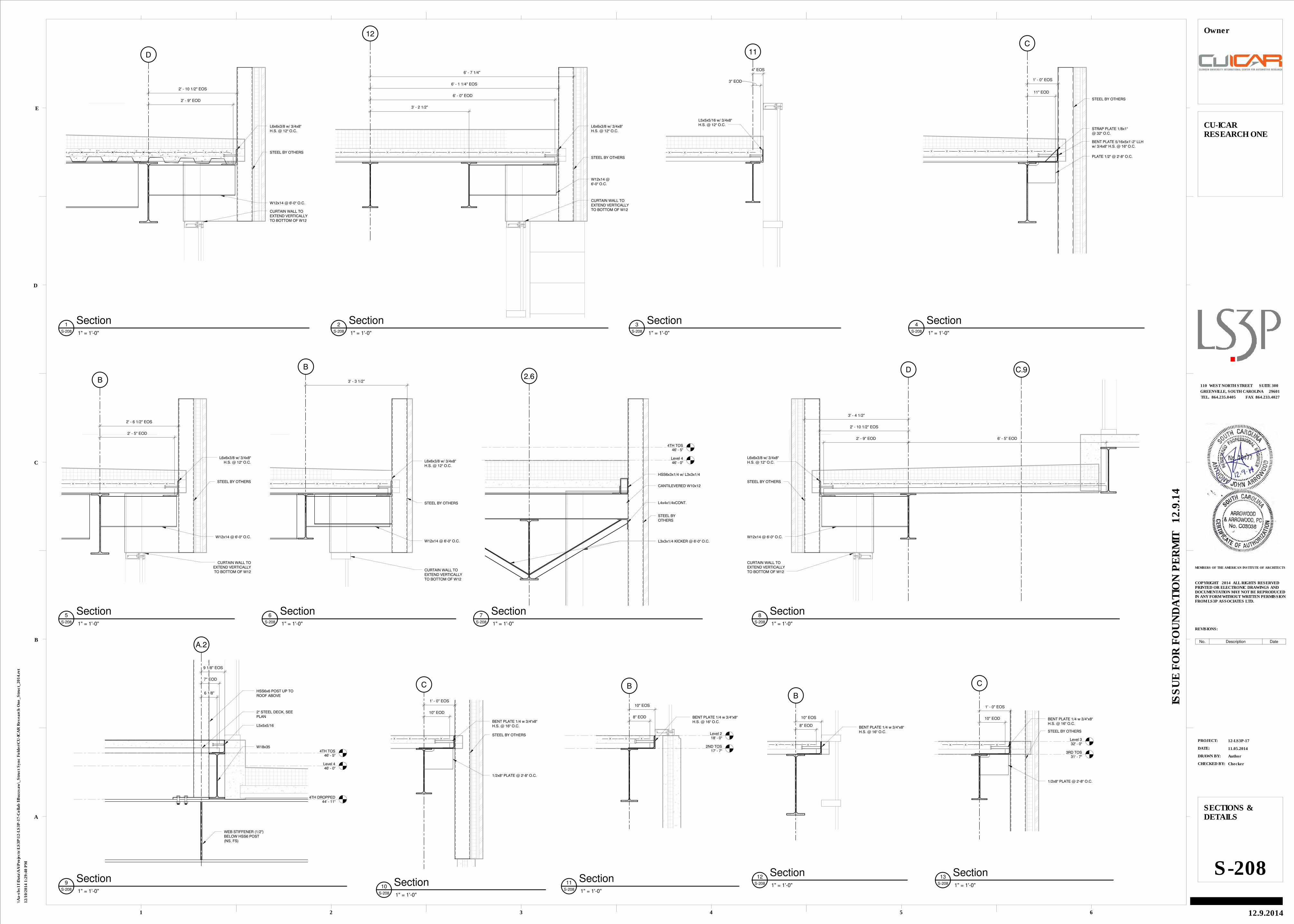
D
2' - 10 1/2" EOS
2' - 9" EOD
W12x14 @ 6'-0" O.C.
L6x6x3/8 w/ 3/4x8"H.S. @ 12" O.C.
STEEL BY OTHERS
CURTAIN WALL TOEXTEND VERTICALLYTO BOTTOM OF W12
12
6' - 7 1/4"
W12x14 @6'-0" O.C.
L6x6x3/8 w/ 3/4x8"H.S. @ 12" O.C.
STEEL BY OTHERS
CURTAIN WALL TOEXTEND VERTICALLYTO BOTTOM OF W12
6' - 1 1/4" EOS
6' - 0" EOD
3' - 2 1/2"
11
4" EOS
3" EOD
L5x5x5/16 w/ 3/4x8"H.S. @ 12" O.C.
C
1' - 0" EOS
BENT PLATE 5/16x5x1'-2" LLHw/ 3/4x8" H.S. @ 16" O.C.
STRAP PLATE 1/8x1"@ 32" O.C.
PLATE 1/2" @ 2'-8" O.C.
11" EOD
STEEL BY OTHERS
B
2' - 6 1/2" EOS
W12x14 @ 6'-0" O.C.
L6x6x3/8 w/ 3/4x8"H.S. @ 12" O.C.
STEEL BY OTHERS
CURTAIN WALL TOEXTEND VERTICALLYTO BOTTOM OF W12
2' - 5" EOD
B
3' - 3 1/2"
W12x14 @ 6'-0" O.C.
L6x6x3/8 w/ 3/4x8"H.S. @ 12" O.C.
STEEL BY OTHERS
CURTAIN WALL TOEXTEND VERTICALLYTO BOTTOM OF W12
Level 446' - 0"
4TH TOS46' - 5"
2.6
STEEL BYOTHERS
L4x4x1/4xCONT.
CANTILEVERED W10x12
HSS6x3x1/4 w/ L3x3x1/4
L3x3x1/4 KICKER @ 6'-0" O.C.
C.9D
W12x14 @ 6'-0" O.C.
L6x6x3/8 w/ 3/4x8"H.S. @ 12" O.C.
STEEL BY OTHERS
CURTAIN WALL TOEXTEND VERTICALLYTO BOTTOM OF W12
3' - 4 1/2"
2' - 10 1/2" EOS
2' - 9" EOD 6' - 5" EOD
Level 446' - 0"
4TH TOS46' - 5"
A.2
4TH DROPPED44' - 11"
W18x35
2" STEEL DECK, SEEPLAN
HSS6x6 POST UP TOROOF ABOVE
L5x5x5/16
WEB STIFFENER (1/2")BELOW HSS6 POST(NS, FS)
6 1/8"
9 1/8" EOS
7" EOD
C
STEEL BY OTHERS
BENT PLATE 1/4 w 3/4"x8"H.S. @ 16" O.C.
1/2x8" PLATE @ 2'-8" O.C.
1' - 0" EOS
10" EOD
Level 218' - 0"
B
2ND TOS17' - 7"
BENT PLATE 1/4 w 3/4"x8"H.S. @ 16" O.C.
10" EOS
8" EOD
B
BENT PLATE 1/4 w 3/4"x8"H.S. @ 16" O.C.
10" EOS
8" EOD
Level 332' - 0"
C
3RD TOS31' - 7"
STEEL BY OTHERS
BENT PLATE 1/4 w 3/4"x8"H.S. @ 16" O.C.
1/2x8" PLATE @ 2'-8" O.C.
1' - 0" EOS
10" EOD
CHECKED BY:
DRAWN BY:
DATE:
PROJECT:
REVISIONS:
MEMBERS OF THE AMERICAN INSTITUTE OF ARCHITECTS
1
A
2 3 4 5 6
B
C
D
E
COPYRIGHT 2014 ALL RIGHTS RESERVEDPRINTED OR ELECTRONIC DRAWINGS ANDDOCUMENTATION MAY NOT BE REPRODUCEDIN ANY FORM WITHOUT WRITTEN PERMISSIONFROM LS3P ASSOCIATES LTD.
TEL. 864.235.0405 FAX 864.233.4027
GREENVILLE, SOUTH CAROLINA 29601
110 WEST NORTH STREET SUITE 300
ISS
UE
FO
R F
OU
ND
AT
ION
PE
RM
IT 1
2.9
.14
12/1
0/2
014 1
:29:4
0 P
M
\\A
a-s
bs11\D
ata
\AA
\Pro
jects
\LS
3P
\12-L
S3P
-17-C
ollab
I\B
uzzsaw
\_S
tru
ct
Syn
c F
old
er\
CU
-IC
AR
Researc
h O
ne_S
tru
ct_
2014.r
vt
12-LS3P-17
11.05.2014
Author
Checker
SECTIONS &DETAILS
S-208
CU-ICARRESEARCH ONE
12.9.2014
Owner
1" = 1'-0"S-208
1 Section 1" = 1'-0"S-208
2 Section 1" = 1'-0"S-208
3 Section 1" = 1'-0"S-208
4 Section
1" = 1'-0"S-208
5 Section 1" = 1'-0"S-208
6 Section 1" = 1'-0"S-208
7 Section 1" = 1'-0"S-208
8 Section
1" = 1'-0"S-208
9 Section
1" = 1'-0"S-208
10 Section 1" = 1'-0"S-208
11 Section 1" = 1'-0"S-208
12 Section 1" = 1'-0"S-208
13 Section
No. Description Date
![Pointers as Structure Members u One reason to use pointers in structure: struct book { float price; char title[50]; char abstract[5000]; }; …… struct book](https://img.pdfslide.us/doc/110x75/56649f2b5503460f94c45d39/pointers-as-structure-members-u-one-reason-to-use-pointers-in-structure-struct.jpg)