Embed Size (px)
Citation preview

Civil Engineering Practice Volume 29, Number 1 ISSN: 0886-9685
28 CIVIL ENGINEERING PRACTICE © Boston Society of Civil Engineers Section / ASCE
Curved Steel Girder Integral Abutment Bridges in Vermont, USA
Scott Civjan1, James Lacroix2, Asako Takeuchi1, and Kristin Higgins2
1 Department of Civil and Environmental Engineering, University of Massachusetts, Amherst MA, USA 2 Vermont Agency of Transportation, Montpelier VT, USA
E-mail: [email protected]
Abstract
The Vermont Agency of Transportation has constructed four curved steel girder integral abutment bridges of varying details that have been in service from three to twelve years. These designs are unique in the New England region and documentation of these designs and performance may aid wider implementation of these bridge types. Spans range from 86 ft. to 140 ft., which are typical of many bridge replacement projects. Arc span divided by girder radius, ranges from 0.067 to 0.358 radians and girder stiffness varies across the spans. Therefore, these structures could not be designed as straight structures per AASHTO guidelines, and published curved bridge design guidelines do not apply to integral abutment structures. Instead, these bridges required special design considerations which were addressed through straightforward design assumptions. Each has distinct characteristics that are notable, from curvature of 23.87 degrees with superelevation and grade change at the Danby Bridge, 30 degree skew and curvature of 2.75 degrees at the Bradford Bridge, and two-span structure with curvature of 11.25 degrees and twelve years in service of the Stockbridge Bridge. Site visits were made to all four structures and the current condition was documented, including any observed cracking. Any distress noted was not attributable to the bridge curvature, but was common to the detailing used. The condition of all four of these bridges is very good, based on author site visits and bridge inspection reports., and they are performing as expected.
Keywords: bridge, jointless, integral abutment, curved, performance, inspection, case study
1. Introduction
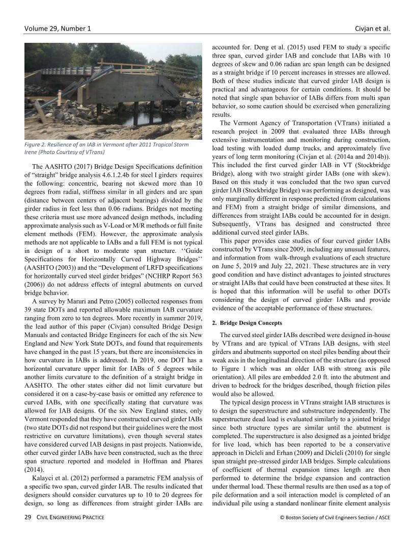
Integral abutment bridges (IABs) are widely used throughoutthe United States as efficient and durable structures. By eliminating expansion joints within the bridge span, the inherent problems associated with failing bridge joints are avoided. In states with harsh winters, such as in New England, failed bridge joints lead to exposure of the superstructure and substructure to anti-icing salts and result in significant corrosion, spalling and other deterioration. IABs can also result in significant initial cost savings due to the minimally invasive foundations, which avoid cofferdams, dewatering requirements, and environmental impacts. Therefore, in this and many regions of the country, IABs become the bridge of choice when appropriate for the design conditions. In addition, IABs are generally more resilient structures, reported to perform well under earthquake excitations and flood conditions. (Figure 1 shows an example where an IAB allowed for a resilient response after Tropical Storm Irene in 2011 in an area where many
There are complications with IABs, however, as making the superstructure integral with the substructure introduces frame action of the entire assembly and introduces significant effects of soil-structure interaction. Prior to completion of the abutments the structure behaves identically to a conventional bridge, as there is no restraint so long as the bearings are designed similarly, which is standard practice in VT. Therefore, superstructure construction issues of girder fit up, cross frames, and dead load distribution can be designed similarly to non-integral designs. Designs of straight IABs of moderate spans can still be done with straightforward assumptions. However, when large skew or any curvature is introduced, appropriate design assumptions are not clear and simplified methods developed for jointed structures are not applicable. This has led many Departments of Transportation (DOTs) to place restrictions on skew or curvature when designing an IAB.
Volume 29, Number 1 Civjan et al.
29 CIVIL ENGINEERING PRACTICE © Boston Society of Civil Engineers Section / ASCE
Figure 2. Resilience of an IAB in Vermont after 2011 Tropical Storm Irene (Photo Courtesy of VTrans)
The AASHTO (2017) Bridge Design Specifications definition of “straight” bridge analysis 4.6.1.2.4b for steel I girders requires the following: concentric, bearing not skewed more than 10 degrees from radial, stiffness similar in all girders and arc span (distance between centers of adjacent bearings) divided by the girder radius in feet less than 0.06 radians. Bridges not meeting these criteria must use more advanced design methods, including approximate analysis such as V-Load or M/R methods or full finite element methods (FEM). However, the approximate analysis methods are not applicable to IABs and a full FEM is not typical in design of a short to moderate span structure. ‘‘Guide Specifications for Horizontally Curved Highway Bridges’’ (AASHTO (2003)) and the “Development of LRFD specifications for horizontally curved steel girder bridges” (NCHRP Report 563 (2006)) do not address effects of integral abutments on curved bridge behavior.
A survey by Maruri and Petro (2005) collected responses from 39 state DOTs and reported allowable maximum IAB curvature ranging from zero to ten degrees. More recently in summer 2019, the lead author of this paper (Civjan) consulted Bridge Design Manuals and contacted Bridge Engineers for each of the six New England and New York State DOTs, and found that requirements have changed in the past 15 years, but there are inconsistencies in how curvature in IABs is addressed. In 2019, one DOT has a horizontal curvature upper limit for IABs of 5 degrees while another limits curvature to the definition of a straight bridge in AASHTO. The other states either did not limit curvature but considered it on a case-by-case basis or omitted any reference to curved IABs, with one specifically stating that curvature was allowed for IAB designs. Of the six New England states, only Vermont responded that they have constructed curved girder IABs (two state DOTs did not respond but their guidelines were the most restrictive on curvature limitations), even though several states have considered curved IAB designs in past projects. Nationwide, other curved girder IABs have been constructed, such as the three span structure reported and modeled in Hoffman and Phares (2014).
Kalayci et al. (2012) performed a parametric FEM analysis of a specific two span, curved girder IAB. The results indicated that designers should consider curvatures up to 10 to 20 degrees for design, so long as differences from straight girder IABs are
accounted for. Deng et al. (2015) used FEM to study a specific three span, curved girder IAB and conclude that IABs with 10 degrees of skew and 0.06 radian arc span length can be designed as a straight bridge if 10 percent increases in stresses are allowed. Both of these studies indicate that curved girder IAB design is practical and advantageous for certain conditions. It should be noted that single span behavior of IABs differs from multi span behavior, so some caution should be exercised when generalizing results.
The Vermont Agency of Transportation (VTrans) initiated a research project in 2009 that evaluated three IABs through extensive instrumentation and monitoring during construction, load testing with loaded dump trucks, and approximately five years of long term monitoring (Civjan et al. (2014a and 2014b)). This included the first curved girder IAB in VT (Stockbridge Bridge), along with two straight girder IABs (one with skew). Based on this study it was concluded that the two span curved girder IAB (Stockbridge Bridge) was performing as designed, was only marginally different in response predicted (from calculations and FEM) from a straight bridge of similar dimensions, and differences from straight IABs could be accounted for in design. Subsequently, VTrans has designed and constructed three additional curved steel girder IABs.
This paper provides case studies of four curved girder IABs constructed by VTrans since 2009, including any unusual features, and information from walk-through evaluations of each structure on June 5, 2019 and July 22, 2021. These structures are in very good condition and have distinct advantages to jointed structures or straight IABs that could have been constructed at these sites. It is hoped that this information will be useful to other DOTs considering the design of curved girder IABs and provide evidence of the acceptable performance of these structures.
2. Bridge Design Concepts
The curved steel girder IABs described were designed in-house by VTrans and are typical of VTrans IAB designs, with steel girders and abutments supported on steel piles bending about their weak axis in the longitudinal direction of the structure (as opposed to Figure 1 which was an older IAB with strong axis pile orientation). All piles are embedded 2.0 ft. into the abutment and driven to bedrock for the bridges described, though friction piles would also be allowed.
The typical design process in VTrans straight IAB structures is to design the superstructure and substructure independently. The superstructure dead load is evaluated similarly to a jointed bridge since both structure types are similar until the abutment is completed. The superstructure is also designed as a jointed bridge for live load, which has been reported to be a conservative approach in Dicleli and Erhan (2009) and Dicleli (2010) for single span straight pre-stressed girder IAB bridges. Simple calculations of coefficient of thermal expansion times length are then performed to determine the bridge expansion and contraction under thermal load. These thermal results are then used as a top of pile deformation and a soil interaction model is completed of an individual pile using a standard nonlinear finite element analysis

Volume 29, Number 1 Civjan et al.
© Boston Society of Civil Engineers Section / ASCE CIVIL ENGINEERING PRACTICE 30
program used by VTrans for pier design. If pile yielding is noted, the pile evaluation is either re-run assuming a pin at the top of pile to introduce full yielding or a larger pile can be selected. Only compact H-pile sections are used.
The curvature in these curved girder IABs was evaluated through straightforward design, using conservative assumptions. The superstructure was designed as a non-integral structure for dead and live loads. For thermal load, the typical pile design was modified to include pile displacements in both longitudinal and transverse directions based upon the angle of the anticipated bridge movement versus the orientation of the abutment. Movement occurring along the chord line between abutments, or to piers if a multi-span bridge, was calculated as the coefficient of thermal expansion times chord length. The longitudinal component of this movement was considered similarly to a straight IAB bridge, and transverse component was used to apply biaxial pile foundation effects, though transverse movement could be ignored if found to be negligible. This analysis results in the inclusion of biaxial bending in pile design.
The design of the Bradford Bridge and Jamaica Bridge, which have minimal to moderate curvature, also relied on the findings of Civjan et al. (2014a and 2014b)) to determine that the effects of these values of curvature were not expected to be significant. Designers were aware of possible additional load demands arising from the girder curvature, but designed the bridges similarly to straight IAB designs.
For the high curvature, superelevation, and grade change at the Danby Bridge much more attention to these effects was included, but the overall design process focused on the modifications to the traditional VTrans IAB design process described above rather than incorporating a significantly more detailed process. A longer span of this curvature would have considered a full three-dimensional finite element model including soil-structure effects, but the focus of the selected bridges was to use simple models for design assumptions. Transverse pile forces and deformations due to curvature were still estimated based on geometric relationships, with more attention paid to the biaxial bending effects in piles. All movement was assumed to occur at the lower bridge elevation, though the higher abutment was subsequently designed to accommodate some movement as well. Vuggy rock conditions required piles be drilled through the vuggy zone and placed in pre-excavated holes that reached competent rock. These site conditions precluded the use of shallow foundations.
The Stockbridge Bridge was the first curved girder IAB constructed by VTrans. This bridge is a two span structure with moderate curvature. As the initial design of its kind, significantly more detailed evaluation of the expected bridge movement was completed to evaluate the curvature than in the other bridges. This included a design concept of orienting the wingwalls such that the total backfill reactions would act in a radial direction along the superstructure, and some methods employed to minimize variation of backfill pressures. These were each accomplished through geometric calculations in order to develop detailing and provide conservative estimates of forces and deformations, but the overall
structure was designed in line with typical VTrans IAB design of straight girder bridges at the time.
The designs of these structures were completed without any significant modifications to typical bridge design practices. Construction and detailing of the structures followed a combination of practices for curved jointed bridges and straight IABs, with some conservative assumptions made to accommodate the non-typical components. These methods can be incorporated into typical design practice without requiring complicated three-dimensional FEM for short to moderate span curved girder bridges of low to moderate curvature.
3. Expected IAB Performance
IAB designs are selected due to their expected improvements to durability and resilience of the structures. By eliminating bridge joints many of the long term corrosion issues with New England bridges can be minimized. However, the resulting soil-structure interactions result in stress distributions and movements that differ from jointed bridges. For VTrans IAB designs some minor cracking in the abutments and wingwalls is typical. These will be noted in the bridge photos, but have had minimal effects on long term performance and appear to stabilize with time in existing IABs.
In the abutment back wall at the bottom flanges of girders there is often a 45 degree crack propagating downward from the corner of bottom flanges. Cracks between an integral wingwall and abutment above the construction joint can occur. These all appear to be stable with time. Minor transverse cracks at regular intervals at the edge of the deck are typical, sometimes propagating across the deck, which can be larger in heavy integral curb or parapet barriers when included along the edge of the deck. Earlier designs (such as the Stockbridge Bridge) exhibited a minor vertical abutment crack between girders. VTrans policy (Structures Engineering Instructions SEI 17-001) since 2017 is to reduce abutment horizontal reinforcing spacing on the interior face to 6 in. to reduce these cracks. Structures with subsequent designs have not exhibited these cracks.
When skew is included in an IAB design some cracking at the acute corner wingwall above the construction joint has occurred. These cracks appear stable with time and are not expected to affect service life as corrosion resistant reinforcing steel is included above the construction joint. Curvature is expected to introduce similar effects as skew, with thermal expansion between corners of the bridge causing out of plane rotations of the structure. This could potentially lead to service issues such as bridge joint deterioration and additional stresses and cracking in the abutments if not accounted for in design.
4. Bridge Descriptions and Evaluations
Each of the structures is presented independently in the following sections. For each bridge, general details are provided including any unusual features of the design, followed by description of any deterioration noted on the walk-through of June 5, 2019, and any new observations from the walk-through of July 22, 2021. The initial evaluations took place the day after a

Volume 29, Number 1 Civjan et al.
31 CIVIL ENGINEERING PRACTICE © Boston Society of Civil Engineers Section / ASCE
rainstorm, allowing for visual observation of any moisture penetration, while the latter followed a dry day. General details of the bridges are found in Table 3.
The definition of curvature used in this paper is the angle in
degrees per 100 feet of central girder arc length
�𝐶𝐶𝐶𝐶𝐶𝐶𝐶𝐶𝐶𝐶𝐶𝐶𝐶𝐶𝐶𝐶𝐶𝐶 =180𝜋𝜋
�100𝑓𝑓𝐶𝐶𝑅𝑅𝐶𝐶𝑅𝑅𝑅𝑅𝐶𝐶𝑅𝑅
��
The AASHTO designation of arc span divided by girder radius will also be included in bridge descriptions.
4.1 Bradford Bridge
The Bradford Bridge (Figures 2 and 3) has a very small curvature and relatively short span but high skew. The bridge replaced a traditional jointed bridge that had a curved deck on straight steel girders. The incremental cost for curved girders rather than straight was approximately 5 cents per pound, so was determined to be worthwhile to improve aesthetics. The single span is 140 ft. between centerline of abutments and has a central radius of 2083 ft. resulting in arc span to radius of 0.067 radians and curvature of 2.75 degrees. There is a superelevation of less than 4 percent (varies along span) at road level and minimal vertical elevation difference between start and end of the bridge. The bridge has a 9 in. exposed deck with longitudinal grooving. Abutments are skewed 30 degrees supported on six HP 12X84 piles oriented with the bridge span that extend approximately 70 ft. and 25 ft. below the Abutments 1 and 2, respectively. The six steel girders are metalized due to the low clearance to the stream water level, which would prohibit weathering steel (less than 10 ft. clearance). Girders are supported by steel reinforced elastomeric pad bearings with a single line of anchor bolts and embedded into the abutments. Girder sizes are 1/2X35 webs and top and bottom flanges of 2X16 and 2-1/2X16 for the four girders at the inside of the curve (Girders 1 through 4), 2-1/2X16 and 3-1/2X16 for the two girders at the outside of the curve (Girders 5 and 6), respectively. Width of the bridge is 31.33 ft. to outside of fascia with galvanized bridge rails. Abutments are 3.5 ft. thick, approximately 10 ft. tall and constructed from a precast lower section and cast in place upper section that also fills the voids in
the lower precast section that encase the pile tops. Wingwalls are also precast concrete sections that are 2.0 ft. thick and extend 7 to
8 ft. from the abutment centerline, connected at the abutment face by dowels and mortar. The bridge was constructed in 2017.
The bridge had been in service for 2 and 4 years when evaluated. The overall condition is very good. There are some minor deck cracks approximately 15 feet and 30 feet from the West abutment and at midspan (Figure 4). These do not progress across the entire deck but are allowing some moisture penetration (there is no waterproofing on this deck).
As is typical in many IAB abutment backwalls, a 45 degree crack propagating from the bottom flange of most girders was observed, on the side of the obtuse angle between girder and abutment (Figure 5). There is a filled joint between the abutment and precast wingwalls, with dowels between the two components providing rigidity. No distress was noted in these details (Figure 6). Due to cost, an asphalt plug joint was used rather than an installed joint option at the end of the approach slab. These joints are failing due to the high skew (Figure 7), and would normally not be used for this skew angle. The joint condition is not attributed to the curved IAB design. The follow up evaluation in 2021 observed slightly more scaling on the top of the abutments (Figure 8), continued deterioration of the asphalt plug joint (Figure 7b), and a very slight increase in efflorescence at cracks, though cracks were less noticeable due to the dry conditions.
Overall, the condition of this bridge is very good and performing as expected. Official bridge inspection reports were completed in 2017 and 2019 and indicated 8 (Very Good) condition ratings for deck, superstructure, and substructure.
Table 3. Bridge Details
Bridge Name Location Lanes carried
Span length (feet)
Curvature (degrees)
Arc Span to Radius (radians)
Skew (degrees)
Year Open
Bradford Bridge 43.987525, -72.138899 2 140 2.75 0.067 30 2017
Jamaica Bridge 43.099619, -72.782144 2 130 8.16 0.185 N/A 2013
Danby Bridge 43.339344, -73.039001 2 86 23.87 0.358 N/A 2018

Volume 29, Number 1 Civjan et al.
© Boston Society of Civil Engineers Section / ASCE CIVIL ENGINEERING PRACTICE 32
Figure 3. Overview of Bradford Bridge
Figure 4. Plan Views of Bradford Bridge (VTrans - Used by Permission)

Volume 29, Number 1 Civjan et al.
33 CIVIL ENGINEERING PRACTICE © Boston Society of Civil Engineers Section / ASCE
Figure 5. Typical Deck Cracking at Bradford Bridge
Figure 6. Crack in Abutment at Girder Bottom Flange at Bradford Bridge
Figure 7. Doweled Precast Wingwall to Abutment at Bradford Bridge
a) 2019 b) 2021
Figure 8. Deteriorating Asphalt Plug Joint at Skewed Bradford Bridge
Figure 9. Scaling at Top of Abutment at Bradford Bridge (2021)
Crack
Crack

Volume 29, Number 1 Civjan et al.
© Boston Society of Civil Engineers Section / ASCE CIVIL ENGINEERING PRACTICE 34
4.2 Jamaica Bridge
The Jamaica Bridge (Figures 9 and 10) has a moderate curvature with no skew. The bridge replaced a two span rolled beam bridge washed out during Tropical Storm Irene. The new single span is 130 ft. between centerline of abutments and has a central radius of 702.5 ft. resulting in arc span to radius of 0.185 radians and curvature of 8.16 degrees. There is a superelevation of 3.2 percent at road level and a vertical elevation difference of 4.05 ft. between start and end of the bridge. The bridge has an 8-1/2 in. deck with a membrane and bituminous pavement. Abutments and wingwalls are cast in place and integral with each other. Abutments are supported on seven HP12X84 piles that extend approximately 25 ft. and 17 ft. below the abutment at Abutments 1 and 2, respectively, and socketed 3 ft. into bedrock. The seven steel girders are of weathering steel and supported by steel reinforced elastomeric pad bearings with no additional constraint, and embedded into the abutments. Girder sizes are 1/2X48 webs and top and bottom flanges of 1X20 and 1-1/4X20 for the four girders at the inside of the curve (Girders 1 through 4), 1-1/4X20 and 2X20 for the next two interior girders (Girders 5 and 6), and 1-1/4X20 and 2-1/4X20 for the exterior girder at the outside of the curve (Girder 7), respectively. Width of the bridge is 41.00 ft. to outside of fascia with galvanized bridge rails integrated with a concrete support and a sidewalk on one side of the structure. Abutments are 3.0 ft. thick and range from approximately 11.5 ft. to 13.5 ft. tall. Wingwalls vary at the two ends of the bridge. Abutment 1 has parallel wingwalls extending the abutment from 4.4 ft. and 12.0 ft. from the fascia, with an additional pile under the longer section. Abutment 2 has perpendicular 1.5 ft. thick wingwalls that are tapered, from approximately 12 feet to 6 feet in height and extending 11.5 ft. from the abutment centerline. However, the connection of the wingwalls differ significantly at Abutment 2. Wingwall 1 has a cold joint with the abutment and specifies mechanical splices and epoxy filler between the wingwall and abutment. Wingwall 2 instead relies on an integrally
cast wingwall and abutment. The intent was to compare the two details. The bridge was constructed in 2013.
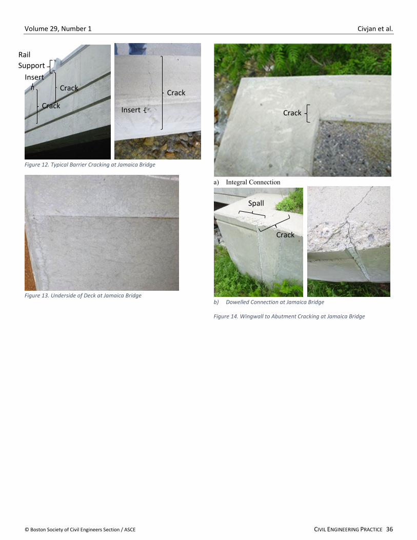
The bridge had been in service for 6 and 8 years when evaluated. The overall condition is very good. The bridge includes a partial concrete barrier below the railing, curb, and sidewalk. As appears typical of these designs for both IAB and non-IAB bridges, cracks have formed at approximately 6 ft. spacing that are wider at the top of barrier and narrower as they extend toward the deck, with some extending to the bottom of deck (Figure 11). At these crack locations, there is efflorescence at and below the top of the road surface. These cracks are at almost every location of form inserts and at a few intermediate rail anchor locations (noted in Figure 11). Additional cracking is found at the sharp transition in concrete barrier height near the abutments. The underside of the deck exhibits some minor map cracking, which may indicate deck curing problems (Figure 12), but was far less noticeable in dry conditions. Both of the in-line wingwalls at Abutment 1 do not show any signs of distress. At Abutment 2, wingwalls are at right angles to the abutment and integral Wingwall 2 at the interior of the curve has minor cracking at 45 degrees at the interior of the abutment and wingwall interface, typical of other IABs (Figure 13a). Wingwall 1 on the outer exterior of the curve has a mechanical splice, epoxy filler and bevel. A large crack has formed at this location, extending through the entire interface, though not following the cold joint, along with some chipped concrete along the outer edge of the abutment and wingwall (Figure 13b). No change was noted in 2021. This detail has poor results and should not be used. It is noted that a relatively similar detail was used at the Bradford Bridge with no distress noted. It should be further investigated whether the difference is due to the tapered wingwall design or detailing implemented. The asphalt plug joints are performing adequately though the thin asphalt seal at the approach slab to bridge deck connection is showing some deterioration. The follow up evaluation in 2021 observed an increase in crack size on parapet locations, slight increase in efflorescence at cracks, though cracks were less noticeable due to
Figure 10. Overview of Jamaica Bridge

Volume 29, Number 1 Civjan et al.
35 CIVIL ENGINEERING PRACTICE © Boston Society of Civil Engineers Section / ASCE
the dry conditions. It was noted that the cracks in the underside of the deck were far less noticeable in the dry conditions.
Overall, the condition of this bridge is very good and performing as expected. All distress noted is typical of these details in general, and is not an effect of the curved IAB structure. Official bridge inspection reports were completed in 2013, 2015, 2017, and 2019 and indicated 8 (Very Good) condition ratings for deck, superstructure, and substructure.
Figure 11. Plan Views of Jamaica Bridge (VTrans - Used by Permission)
Volume 29, Number 1 Civjan et al.
© Boston Society of Civil Engineers Section / ASCE CIVIL ENGINEERING PRACTICE 36
Figure 12. Typical Barrier Cracking at Jamaica Bridge
Figure 13. Underside of Deck at Jamaica Bridge
a) Integral Connection
b) Dowelled Connection at Jamaica Bridge
Figure 14. Wingwall to Abutment Cracking at Jamaica Bridge
Insert
Crack
Rail Support
Insert
Crack
Crack
Crack
Spall
Crack

Volume 29, Number 1 Civjan et al.
37 CIVIL ENGINEERING PRACTICE © Boston Society of Civil Engineers Section / ASCE
4.3 Danby Bridge
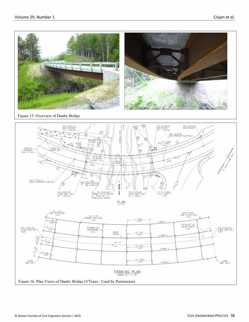
The Danby Bridge (Figures 14 and 15) has the highest curvature of these structures and is expected to push the limits of curved girder IAB design, relatively short span, no skew, and high superelevation. The bridge replaced a 74 ft. single span rolled beam bridge constructed in 1933.The new single span is 86 ft. between centerline of abutments and has a central radius of 240 ft. resulting in arc span to radius of 0.358 radians and a curvature of 23.87 degrees. There is a superelevation of 5.6 percent at road level and a vertical elevation difference of 4.02 ft. between start and end of the bridge. The bridge has a 9 in. exposed deck with longitudinal grooving. Abutments are cast in place and integral with wingwalls at Abutment 2. Abutments are supported on four HP12X74 piles that extend approximately 20 ft. below the abutment. Conditions at the site included a layer of vuggy rock which was deemed unsuitable for shallow foundations. Holes were drilled through this layer and pile tips placed on competent bedrock. The four steel girders are of weathering steel, supported by steel reinforced elastomeric pad bearings with a single line of anchor bolts, and embedded into the abutments. Girder sizes are 1/2X42 webs and top and bottom flanges of 7/8X18 for the twor girders at the inside of the curve (Girders 1 and 2) and 7/8X18 and 2-1/4X18 for the two girders at the outside of the curve (Girders 3 and 4), respectively. The significantly different cross sections from the inner to outer girders are due to the sharp curvature. Width of the bridge is 25.33 ft. to outside of fascia with galvanized bridge rails attached to the outer fascia. Abutments are 3.0 ft. thick and range from approximately 13.0 ft. to 14.5 ft. tall. Abutment 1 (higher elevation) has 1.5 ft. thick precast modular retaining walls perpendicular to the abutment extending 12.5 ft. and 14.5 ft. from the abutment, with a flexible joint between the walls and abutment. Abutment 2 (lower elevation) has integral wingwalls, both extending 8.0 ft. from the abutment centerline, with one perpendicular to the abutment and the other skewed 30 degrees. The bridge was constructed in 2018.
The bridge had been in service for 1 and 3 years when evaluated. The overall condition is excellent with only a few minor cracks at the girder bottom flange (Figure 16). To date, there is no cracking at the integral wingwall to Abutment 2 detail (Figure 17). The retaining walls at Abutment 1 are not flush with the back wall, with vertical misalignment approximately 1 in. at the top of the abutment (Figure 18). It appears that this was the condition at the completion of construction as there is no distress of the sealant between the components or soil at the base of the walls. The follow up evaluation in 2021 noted that the misalignment was nearly identical (at similar ambient temperature), with the only change being that the sealant had dried and pulled away from the joint. This will be monitored in future years to look for signs of bridge twisting in plan view. Some new, but minor, efflorescence at cracks bottom flange corners and staining from weathering steel was also observed.
Overall, the condition of this bridge was excellent and performing as expected. Official bridge inspection reports were completed in 2018 and 2020 and indicated 8 (Very Good) condition ratings for deck, superstructure, and substructure.
Volume 29, Number 1 Civjan et al.
© Boston Society of Civil Engineers Section / ASCE CIVIL ENGINEERING PRACTICE 38
Figure 15. Overview of Danby Bridge
Figure 16. Plan Views of Danby Bridge (VTrans - Used by Permission)

Volume 29, Number 1 Civjan et al.
39 CIVIL ENGINEERING PRACTICE © Boston Society of Civil Engineers Section / ASCE
a) 2019
b) 2021
Figure 17. Crack in Abutment at Girder Bottom Flange at at Danby Bridge
4.4 Stockbridge Bridge
The Stockbridge Bridge is a two span structure that has a moderate curvature and no skew (Figures 19 and 20). The bridge replaced a traditional jointed three span curved I-Girder bridge. This bridge is notable for several reasons. It was the first curved girder integral abutment bridge constructed by VTrans and was part of an extensive instrumentation program (results of this instrumentation and monitoring are reported elsewhere (Civjan et al. (2014a and 2014b)). The bridge was constructed in 2009, so has twelve years of service, significantly more than the other structures. It was also in service during Tropical Storm Irene, which overtopped the structure and resulted in a large tree and other debris impacting the side of the structure. It is noteworthy that many other bridges along the White River were washed out in the event, but the Stockbridge Bridge was fully functional post-event. The design of this structure also had some interesting features that make it non-typical. Geofoam was installed between the back wall and backfill soil at each abutment, with the intention of evening out and lowering abutment soil pressures. From
instrumentation readings this appeared to be effective, as backfill soil pressures were lower than those obtained in the two other structures that were instrumented which each had significantly shorter spans (though those were single span structures) and pressures were lower than predicted from finite element modeling. In addition, the wingwall design was completed with the specific intent of counteracting curvature effects.
Figure 18. Wingwall to Abutment 2 Connection at Danby Bridge
a) Downstream b) Upstream
Figure 19. Retaining Wall to Abutment 1 Detail at Danby Bridge
Crack
Crack

Volume 29, Number 1 Civjan et al.
© Boston Society of Civil Engineers Section / ASCE CIVIL ENGINEERING PRACTICE 40
Figure 20. Overview of Stockbridge Bridge
Figure 21. Plan Views of Stockbridge Bridge (VTrans - Used by Permission)
Volume 29, Number 1 Civjan et al.
41 CIVIL ENGINEERING PRACTICE © Boston Society of Civil Engineers Section / ASCE
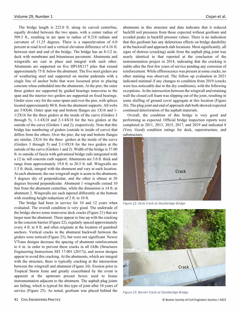
The bridge length is 222.0 ft. along its curved centerline, equally divided between the two spans, with a center radius of 509.3 ft., resulting in arc span to radius of 0.218 radians and curvature of 11.25 degrees. There is a superelevation of 6.0 percent at road level and a vertical elevation difference of 4.16 ft. between start and end of the bridge. The bridge has an 8-1/2 in. deck with membrane and bituminous pavement. Abutments and wingwalls are cast in place and integral with each other. Abutments are supported on five HP14X117 piles that extend approximately 75 ft. below the abutment. The five steel girders are of weathering steel and supported on mortar pedestals with a single line of anchor bolts that were loosened prior to placing concrete when embedded into the abutments. At the pier, the outer three girders are supported by guided bearings transverse to the span and the interior two girders are supported on fixed bearings. Girder sizes vary for the outer spans and over the pier, with splices located approximately 80 ft. from the abutment supports. All webs are 5/8X46. Outer span top and bottom flanges are 1X16 and 1-1/2X16 for the three girders at the inside of the curve (Girders 3 through 5), 1-1/4X18 and 2-1/4X18 for the two girders at the outside of the curve (Girders 1 and 2), respectively. Note that this bridge has numbering of girders (outside to inside of curve) that differs from the others. Over the pier, the top and bottom flanges are similar, 2X16 for the three girders at the inside of the curve (Girders 3 through 5) and 2-1/4X18 for the two girders at the outside of the curve (Girders 1 and 2). Width of the bridge is 37.00 ft. to outside of fascia with galvanized bridge rails integrated with a 12 in. tall concrete curb support. Abutments are 3.0 ft. thick and range from approximately 19.0 ft. to 20.5 ft. tall. Wingwalls are 1.5 ft. thick, integral with the abutment and vary at each location. At each abutment, the one wingwall angle is acute to the abutment, 5 degrees shy of perpendicular, and the other is obtuse at 20 degrees beyond perpendicular. Abutment 1 wingwalls extend 10 feet from the abutment centerline, while the dimension is 14 ft. at abutment 2. Wingwalls are each tapered differently at the bottom with resulting height reductions of 2 ft. to 10 ft.
The bridge had been in service for 10 and 12 years when evaluated. The overall condition is very good. The underside of the bridge shows some transverse deck cracks (Figure 21) that are larger near the abutment. These appear to line up with the cracking in the concrete barrier (Figure 22), regularly spaced approximately every 4 ft. to 8 ft. and often originate at the location of guardrail anchors. Vertical cracks in the abutment backwall between the girders were noticed (Figure 23), but were not significant. Newer VTrans designs decrease the spacing of abutment reinforcement to 6 in. in order to prevent these cracks in all IABs (Structures Engineering Instructions SEI 17-001 (2017)), and newer designs appear to avoid this cracking. At the abutments, which are integral with the structure, there is typically cracking at the intersection between the wingwall and abutment (Figure 24). Erosion prior to Tropical Storm Irene and greatly exacerbated by the event is apparent at the upstream precast boxes used to house instrumentation adjacent to the abutment. The asphalt plug joints are failing, which is typical for this type of joint after 10 years of service (Figure 25). As noted, geofoam was placed behind the
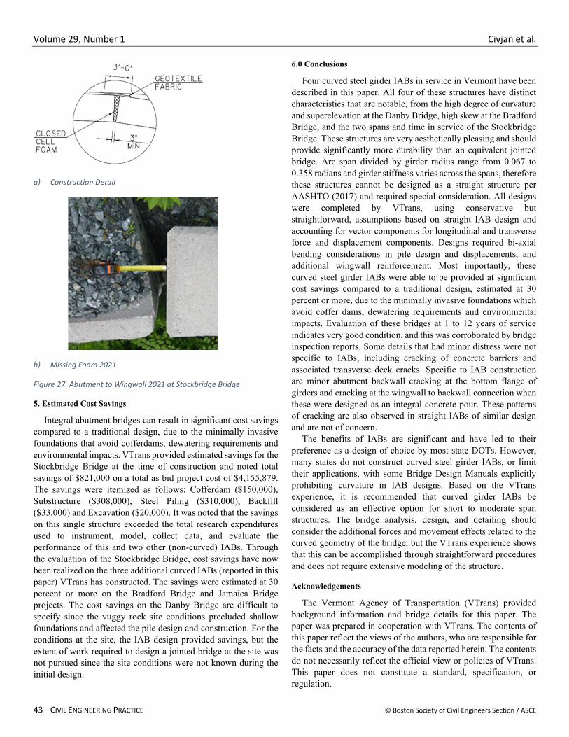
abutments in this structure and data indicates that it reduced backfill soil pressures from those expected without geofoam and avoided peaks in backfill pressure values. There is no indication that this geofoam has any deleterious effects on bridge durability at the backwall and approach slab locations. Most significantly, all signs of distress (cracking) aside from the asphalt plug joint was nearly identical to that reported at the conclusion of the instrumentation project in 2014, indicating that the cracking is stable after the first few years of service pending any corrosion of reinforcement. While efflorescence was present at some cracks, no other staining was observed. The follow up evaluation in 2021 indicated minimal if any changes to condition from 2019 (cracks were less noticeable due to the dry conditions), with the following exceptions. At the intersection between the wingwall and retaining wall the closed cell foam was slipping out of the joint, resulting in some sluffing of ground cover aggregate at this location (Figure 26). The plug joint and end of approach slab both showed expected continued deterioration of the asphalt materials.
Overall, the condition of this bridge is very good and performing as expected. Official bridge inspection reports were completed in 2011, 2013, 2015, 2017, and 2019 and indicated 8 (Very Good) condition ratings for deck, superstructure, and substructure.
Figure 22. Deck Crack at Stockbridge Bridge
Figure 23. Barrier Crack at Stockbridge Bridge
Crack
Crack

Volume 29, Number 1 Civjan et al.
© Boston Society of Civil Engineers Section / ASCE CIVIL ENGINEERING PRACTICE 42
Figure 24. Vertical Abutment Crack at Stockbridge Bridge
Figure 25. Abutment to Wingwall Connection Crack at Stockbridge Bridge
Figure 26. Deteriorated Asphalt Plug Joint at Stockbridge Bridge
Vertical Crack
Crack
Volume 29, Number 1 Civjan et al.
43 CIVIL ENGINEERING PRACTICE © Boston Society of Civil Engineers Section / ASCE
a) Construction Detail
b) Missing Foam 2021
Figure 27. Abutment to Wingwall 2021 at Stockbridge Bridge
5. Estimated Cost Savings
Integral abutment bridges can result in significant cost savings compared to a traditional design, due to the minimally invasive foundations that avoid cofferdams, dewatering requirements and environmental impacts. VTrans provided estimated savings for the Stockbridge Bridge at the time of construction and noted total savings of $821,000 on a total as bid project cost of $4,155,879. The savings were itemized as follows: Cofferdam ($150,000), Substructure ($308,000), Steel Piling ($310,000), Backfill ($33,000) and Excavation ($20,000). It was noted that the savings on this single structure exceeded the total research expenditures used to instrument, model, collect data, and evaluate the performance of this and two other (non-curved) IABs. Through the evaluation of the Stockbridge Bridge, cost savings have now been realized on the three additional curved IABs (reported in this paper) VTrans has constructed. The savings were estimated at 30 percent or more on the Bradford Bridge and Jamaica Bridge projects. The cost savings on the Danby Bridge are difficult to specify since the vuggy rock site conditions precluded shallow foundations and affected the pile design and construction. For the conditions at the site, the IAB design provided savings, but the extent of work required to design a jointed bridge at the site was not pursued since the site conditions were not known during the initial design.
6.0 Conclusions
Four curved steel girder IABs in service in Vermont have been described in this paper. All four of these structures have distinct characteristics that are notable, from the high degree of curvature and superelevation at the Danby Bridge, high skew at the Bradford Bridge, and the two spans and time in service of the Stockbridge Bridge. These structures are very aesthetically pleasing and should provide significantly more durability than an equivalent jointed bridge. Arc span divided by girder radius range from 0.067 to 0.358 radians and girder stiffness varies across the spans, therefore these structures cannot be designed as a straight structure per AASHTO (2017) and required special consideration. All designs were completed by VTrans, using conservative but straightforward, assumptions based on straight IAB design and accounting for vector components for longitudinal and transverse force and displacement components. Designs required bi-axial bending considerations in pile design and displacements, and additional wingwall reinforcement. Most importantly, these curved steel girder IABs were able to be provided at significant cost savings compared to a traditional design, estimated at 30 percent or more, due to the minimally invasive foundations which avoid coffer dams, dewatering requirements and environmental impacts. Evaluation of these bridges at 1 to 12 years of service indicates very good condition, and this was corroborated by bridge inspection reports. Some details that had minor distress were not specific to IABs, including cracking of concrete barriers and associated transverse deck cracks. Specific to IAB construction are minor abutment backwall cracking at the bottom flange of girders and cracking at the wingwall to backwall connection when these were designed as an integral concrete pour. These patterns of cracking are also observed in straight IABs of similar design and are not of concern.
The benefits of IABs are significant and have led to their preference as a design of choice by most state DOTs. However, many states do not construct curved steel girder IABs, or limit their applications, with some Bridge Design Manuals explicitly prohibiting curvature in IAB designs. Based on the VTrans experience, it is recommended that curved girder IABs be considered as an effective option for short to moderate span structures. The bridge analysis, design, and detailing should consider the additional forces and movement effects related to the curved geometry of the bridge, but the VTrans experience shows that this can be accomplished through straightforward procedures and does not require extensive modeling of the structure.
Acknowledgements
The Vermont Agency of Transportation (VTrans) provided background information and bridge details for this paper. The paper was prepared in cooperation with VTrans. The contents of this paper reflect the views of the authors, who are responsible for the facts and the accuracy of the data reported herein. The contents do not necessarily reflect the official view or policies of VTrans. This paper does not constitute a standard, specification, or regulation.

Volume 29, Number 1 Civjan et al.
© Boston Society of Civil Engineers Section / ASCE CIVIL ENGINEERING PRACTICE 44
References
American Association of State and Highway Transportation Officials LRFD Bridge Design Specifications 8th edition (with supplemental updates) (2017). AASHTO. Washington DC.
American Association of State and Highway Transportation Officials Guide Specifications for Horizontally Curved Highway Bridges. (2003) AASHTO. Washington DC.
Civjan, S., Kalayci, E., Breña, S., Quinn, B., Allen, C. (2014a) Performance Monitoring of Jointless Bridges- Phase III- Final Report Part I. Rep. no. 2014-07. Vermont Agency of Transportation and Federal Highway Administration.
Civjan, S., Quinn, B., Breña S., Kalayci, E., Allen, C. (2014b) Performance Monitoring of Jointless Bridges- Phase III- Final Report Part II. Rep. no. 2014-07. Vermont Agency of Transportation and Federal Highway Administration.
Deng, Y. Phares, B. M. Greimann, L., Shryack, G. L. and Hoffman, J. J. (2015) “Behavior of curved and skewed bridges with integral abutments” Journal of Constructional Steel Research. Elsevier. V109. Pp 115-136.
Dicleli, M. and Erhan, S. (2009) “Live Load Distribution Formulas for Single-Span Prestressed Concrete Integral Abutment Bridge Girders” Journal of Bridge Engineering. ASCE. 14(6). Pp. 472-486.
Dicleli, M. (2010) “Effect of superstructure-abutment continuity on live load distribution in integral abutment bridge girders” Structural Engineering and Mechanics. Techno Press. 34(5). Pp. 635-662.
Hoffman, J. and Phares, B. (2014) “Thermal Load Design Philosophies for Horizontally Curved Girder Bridges with Integral Abutments” Journal of Bridge Engineering. ASCE. 19(5).
Kalayci, E., Civjan, S. A. and Breña, S. F. (2012) Parametric study on the thermal response of curved integral abutment bridges. Engineering Structures. Elsevier. V43. Pp 129-138.
Maruri R. and Petro S. (2005) Integral abutments and jointless bridges 2004 survey summary. The 2005 FHWA conference (integral abutments and jointless bridges). FHWA. Baltimore, MD.
National Cooperative Highway Research Program Development of LRFD Specifications for Horizontally Curved Steel Girder Bridges. Report 563. (2006) Transportation Research Board, Washington (DC).
Structures Engineering Instructions SEI 17-001 (2017) Integral Abutment – Backwall Cracking Mitigation. VTrans. https://vtrans.vermont.gov/sites/aot/files/highway/documents/structures/SEI%2017-001.pdf Accessed 7/23/2021