Embed Size (px)
Citation preview

Curvature-Induced Instabilities of Shells
Matteo Pezzulla,1 Norbert Stoop,2 Mark P. Steranka,1 Abdikhalaq J. Bade,1 and Douglas P. Holmes1, ∗
1Department of Mechanical Engineering, Boston University, Boston, MA, 02215.2Department of Mathematics, Massachusetts Institute of Technology - Cambridge, MA, 02139.
(Dated: January 29, 2018)
Induced by proteins within the cell membrane or by differential growth, heating, or swelling,spontaneous curvatures can drastically affect the morphology of thin bodies and induce mechani-cal instabilities. Yet, the interaction of spontaneous curvature and geometric frustration in curvedshells remains poorly understood. Via a combination of precision experiments on elastomeric spher-ical shells, simulations, and theory, we show how a spontaneous curvature induces a rotationalsymmetry-breaking buckling as well as a snapping instability reminiscent of the Venus fly trap clo-sure mechanism. The instabilities, and their dependence on geometry, are rationalized by reducingthe spontaneous curvature to an effective mechanical load. This formulation reveals a combinedpressurelike term in the bulk and a torquelike term in the boundary, allowing scaling predictionsfor the instabilities that are in excellent agreement with experiments and simulations. Moreover,the effective pressure analogy suggests a curvature-induced subcritical buckling in closed shells. Wedetermine the critical buckling curvature via a linear stability analysis that accounts for the combi-nation of residual membrane and bending stresses. The prominent role of geometry in our findingssuggests the applicability of the results over a wide range of scales.
PACS numbers: 02.40.Yy, 87.17.Pq, 02.40.-k, 87.10.Pq
Owing to their slender geometry, thin elastic shellsdisplay intriguing mechanical instabilities. Perhaps themost iconic example is the buckling of a spherical shellunder pressure - a catastrophic situation that often leadsto structural failure [1, 2]. Instabilities and shape changesare also fundamental during the development and mor-phogenesis of thin tissue [3, 4]. To control and evolveshape, Nature heavily relies on internal stimuli such asgrowth, swelling, or active stresses [5, 6]. If the stimulusvaries through the thickness of the shell, it generally in-duces a change of the spontaneous (or natural) curvatureof the tissue [7]. Examples are the ventral furrow forma-tion in Drosophila [8] or the fast closure mechanism in-voked by the Venus fly trap to catch prey [9]. Harnessingsimilar concepts for technological applications, internalstimuli were also suggested as a means to design adap-tive metamaterials [10] and soft robotics actuators [11].To describe the mechanics of slender structures with ar-bitrary stimuli, classical shell mechanics was extendedrecently to model bodies that do not possess a stress-free configuration [12–14], leading to the non-Euclideanshell theory [15]. Despite recent progress [16, 17], therole of curvature-altering stimuli, and their interplay withgeometric frustration and instabilities in thin, initiallycurved shells, remains poorly understood.
In this Letter, we combine precision experiments withnon-Euclidean shell theory to reveal how curvature stim-uli induce mechanical instabilities in spherical shells. Ourexperiments demonstrate symmetry-breaking as well assnap-through shape transitions depending on the amountof stimulus and the deepness of the shell. To rationalizeour findings, we show that a curvature stimulus reducesto a pressure-like normal force in the bulk, but induces atorque along the boundary of the shell. A scaling analy-
sis of the dominant boundary term allows us to constructan analytical phase diagram that captures well the tran-sitions found in experiments and simulations. For closedspherical shells, we show that the pressure-like stimulusinduces a curvature-controlled buckling instability. Thecritical stimulus is obtained from stability analysis andfound to be in the range of related biological systems.
In our experiments, we uniformly coated a rigidsphere (radii R ∈ [12, 75] mm) with silicone-based vinyl-polysiloxane (VPS) 32 (Zhermack), such that it ther-mally crosslinks into an elastomeric shell [18]. We thenrepeated the coating process with VPS 8, and cut shellswith opening angles θ ∈ [20, 150]◦, resulting in bilayershells of thicknesses h ∈ [0.5, 1.3] mm. Due to differ-ential swelling between the two polymer layers, internalstresses develop. We quantify this geometric frustrationby cutting a long, narrow strip from the shell. Free of anyconstraints, the strip adopts a shape with curvature κ,which can be additively decomposed into the initial cur-vature −1/R and natural curvature κ. Thus, κ = κ+1/Rmeasures the curvature stimulus (Fig. 1 (a)) [17, 19].Specifically, for a bilayer with VPS 8 on the outside,we find κ > 0, and by switching the order of the lay-ers, we can induce a negative natural curvature (κ < 0).To characterize the various geometries, we introduce thedimensionless parameter θ = θ/
√h/R, describing the
deepness of the shell with respect to the angular widthof the boundary layer
√h/R [20].
For shells with κ < 0, we find that the stimulus leadsto a loss of rotational symmetry via a supercritical buck-ling bifurcation (Fig. 1 (c)) [3]. Experiments suggest nostrong dependence of this transition on θ. For κ > 0, thestimulus acts to evert the initial curvature of the shell.Above a critical stimulus, we observe a snap-through in-
arX
iv:1
706.
0388
8v2
[co
nd-m
at.s
oft]
26
Jan
2018

2
κ > 0 κ < 0
R
θ
◦a3
tq · t
q · tWedge, torque-like
Wbulk, p-like
κR = 0
κR = 3
κR = 5
κR = 0
κR = −1
κR = −3
a. b.
c. d.
κ > 0
h1
−1/R+κ
FIG. 1. (a) Schematic of a VPS bilayer shell with natu-ral radius of curvature 1/(−1/R + κ) induced by residualswelling. (b) The natural curvature mechanically correspondsto torques on the boundary and a pressure field in the bulk.(c) Buckling of open spherical shells triggered by κ < 0, (left:experiments; right: simulations). (d) Snapping of open spher-ical shells triggered by κ > 0 for θ = 5. Scale bars 2 cm.
stability (Fig. 1 (d)), reminiscent of the abrupt concave-convex shape changes employed by the Venus fly trap [9],and the embryonic inversion of Volvox [21]. Here, thecritical curvature stimulus increases with θ. Moreover,shallow shells with θ < θs ≈ 2 do not snap, whereasshells with θ < θc ≈ 4 remain rotationally symmetric af-ter snapping, while deep ones break the rotational sym-metry during snap-through (Fig. 2).
To explain the richness of the experimental findings,we rely on non-Euclidean shell theory that has recentlybeen proposed as a model for growth in thin, bidimen-sional bodies [15]. In this formulation, the mechan-ics of the shell is entirely described by the geometryof the middle-surface with first and second fundamentalforms a,b [22]. The undeformed reference configuration
in absence of curvature stimulus is characterized by◦a,
◦b,
respectively. Curvature stimuli are modeled by changingthe reference configuration to effectively generate stressesand moments arising from differential swelling of the shelllayers [23]. The resulting natural configuration has fun-damental forms a, b and is generally not embeddablein Euclidean space. When the stimulus does not in-duce a stretch of the mid-surface (a =
◦a), one obtains
b =◦b + κ
◦a, where κ is the scalar (additive) natural cur-
vature [23]. The energy of the shell may be written after
some algebra as [24]
U = UK
s +h2
3UK
b −2(1 + ν)h2
3
∫κ tr (b−
◦b) dω . (1)
Here, UK= UK
s + h2UK
b /3 is Koiter’s classical shell en-ergy composed of stretching and bending terms with-out any inelastic stimuli [24, 25], ν is the Poisson ratio(ν = 1/2 for VPS), and dω is the area element [26]. Ow-ing to the additive decomposition, we can interpret thelast term in (1) as the stimulus-induced curvature poten-
tial Pκ = −2(1 + ν)h2/3∫κ tr (b −
◦b) dω. The surpris-
ingly simple additive effect of natural curvature allowsfor a relatively straightforward extension of thin shellssimulation methods to minimize (1) for a given stimu-lus κ. Indeed, by numerically minimizing Eq. (1), wefind good quantitative agreement with the experimentalshapes and the stimulus-induced transitions (Fig. 1 (c,d)). This suggests that the reduced-order model (1) isadequate to describe thin shells with curvature stimuli.
To theoretically understand how natural curvature in-teracts with the geometry and triggers the observed in-stabilities, we analyze the curvature potential and pro-vide its geometrical interpretation. We start by expand-
ing tr (b−◦b) in terms of the displacement field Ψ up to
first order [20]. Assuming a homogeneous natural curva-ture stimulus κ, the curvature potential decouples intobulk and boundary terms, Pκ = −Wbulk − Wedge [24].For a sphere with outward pointing normal, they read
Wbulk = −4(1 + ν)
3
( hR
)2κ
∫Ψ3 dω , (2a)
Wedge =2(1 + ν)
3h2κ
∮ (q− Ψ
R
)· t ds , (2b)
where Ψ3 is the normal displacement, Ψ is the in-planedisplacement field, and t is the outward normal vector tothe boundary curve. q = ∇Ψ3 − Ψ/R represents the ro-tation of an element of the shell [20], such that q ·t is therotation of t (Fig. 1 (b)). The integral in (2a) is equiv-alent to the first-order energy of a pressure load. In thebulk, a curvature stimulus is therefore equivalent to an ef-fective applied pressure. In (2b), κ is the work conjugateof the rotation q · t and the membrane in-plane displace-ment Ψ · t, implying both a torquelike and membraneforce-like behavior. Specifically, for κ > 0, Eq. (2b) de-scribes an outward torque at the boundary (Fig. 1 (b)). Asimilar interpretation holds for arbitrary open shells [24].
Numerically, we find that |Wedge| � |Wbulk| for thinshells of all considered opening angles θ. We can ratio-nalize this by considering small displacements. The Koi-
ter elastic energy then scales as UK ∼ (Ψ3/R)2R2, whilethe curvature potential scales as Pκ ∼ h2κ(Ψ3/R
2)R2
in the bulk. A balance of the two leads to Ψ3 ∼ h2κ.As the area of the shell is proportional to R2(1− cos θ),the bulk work (2a) scales as Wbulk ∼ h4κ2(1 − cos θ).

3
Then, as the boundary layer is bending dominated [27],we obtain |q − Ψ/R| ∼ κ
√Rh [24], where
√Rh is the
characteristic width of the boundary layer [20]. As theperimeter of the boundary is proportional to R sin θ, weconclude that the edge work (2b) scales as Wedge ∼h4κ2(R/h)3/2 sin θ. By a comparison of the two scalings,we find |Wedge/Wbulk| ∼ (R/h)3/2/ tan(θ/2) � 1, i.e.the boundary work dominates for the opening angles θconsidered. Therefore, the boundary term dictates theobserved shape transitions.
In experiments, we observe that snapping is indeed ac-companied by minimal bulk deformation, but large ro-tation of the boundary. Moreover, we find that snap-through instabilities occur for open shells with θ ≤ π/2when their tangent plane on the boundary becomes ap-proximately horizontal (see the supplementary videos).In this state, the critical curvature within the boundarylayer scales as bc ∼ (1 + ν)(−1/R + κ) [24]. Since thewidth of the boundary layer scales as
√Rh, bc must also
scale as ∼ θ/√Rh. Thus we find that the critical curva-
ture stimulus at snapping κsR ∼ θ, that is
κsR = βθ − α , (3)
leaving two scaling coefficients α and β to be determinedlater. For θ → 0, shells tend to plates. Flat platesof radius r under curvature stimuli bifurcate at κph =
±a(h/r)2 with a =√
10 + 7√
2 [17]. Then, for large Rand small θ, but r = Rθ finite, shells are expected tobehave like plates if we identify κpR = κpR − 1, i.e. wecompensate for the initial curvature −1/R. Therefore,shells will bifurcate at κpR = ±a/θ2 + 1, and we expecta symmetric bifurcation behavior around κR = 1. With-out loss of generality, we consider the case κ < 0, corre-sponding to the buckling of shells into spindle-like shapes.We define the critical curvature stimulus by κb, andnow consider the behavior of deep shells. We note thatfor θ → π, the natural curvature will expend a torquelikework on a boundary whose perimeter approaches zeroas sin θ, while the area of the shell to be deformed in-creases as (1 − cos θ). The critical natural curvaturewill then diverge as κbR ∼ tan(θ/2) ∼ 1/(θ − π), thatis 1/(θ − π
√R/h). We conjecture that the curvature
buckling of shells can be determined by combining thetwo diverging regimes for small and large θ as
κbR = − a
θ2+ 1 +
b
θ − π√R/h
+ c , (4)
where a was given above, and b and c have to be deter-mined by fitting to simulations. Notice that the superpo-sition of the two scalings retains the correct asymptoticbehaviors as θ → 0 and θ → π
√R/h.
Our theoretical scaling predictions can be summarizedin a phase diagram (solid lines in Fig. 2) in the pa-rameters (θ, κR), which fully characterize the curvature-induced instabilities of open shells. For κ < 0, the scaling
0 2 4 6 8 10−2
0
2
4
6
8
-1/θ2∼
∼ 1/θ2
θs θc
κsβ
1
κb
θ
κR
h/R10−1
10−3
FIG. 2. Phase diagram of curvature-induced instabilities inopen shells: white and green regions denote phases with ro-tational symmetry but opposite surface orientations, whereasblue regions denote phases of broken rotational symmetry.Theoretical transitions curves (solid lines) match well withexperimental (colored full symbols) and numerical (coloredempty symbols) findings, where color represents h/R.
law (4) with b = 3.6 and c = −0.98 provides the best fitwith numerics, and agrees well with experiments. Wenote that a parameter-free determination of the bucklingthreshold would require a linear stability analysis, whichis hampered due to the nontrivial fundamental state be-fore buckling. For κ > 0, the behavior is richer: thereare two phases of inverted curvature, one with broken ro-tational symmetry (blue region), and another phase thatis rotationally symmetric (green). Simulations confirmthe snapping transition (3) with α = 0.67 and β = 0.85,but only if θ > θs = 2.09, in agreement with experi-ments. For θ < θs, we find that shells smoothly inverttheir curvature into the green phase as κ increases. Thiscan be understood by considering a family of shells witha fixed h/R, and different θ. Since the width of theboundary layer scales as
√Rh, shallower shells possess
a boundary layer that covers a larger portion of the areacompared to deeper shells. Thus, there exists a criti-cal value θs below which the boundary layer transitionsinto a wide region that covers the entire shell. As re-gions within the boundary layer are bending-dominated,the curvature of the shell smoothly follows the evolu-tion of the spontaneous curvature for θ < θs. Startingfrom the green phase, rotational symmetry is eventu-ally lost for large κR. The transition line is well de-scribed by mirroring Eq. (4) around the axis of symme-try κR = 1, as expected from the plate limit (dashedgray line), without any changes of the parameters b and c.At θc, this transition line intersects with Eq. (3), and atriple point emerges. Explicitly, the triple point is deter-

4
mined from −κs + 2/R = κb, which gives θc = 3.85, inagreement with experiments (θc = 3.95 ± 0.26). Conse-quently, shells snap into a rotationally symmetric phaseonly if θs < θ < θc, whereas for θ > θc, shells imme-diately snap into an everted state of broken rotationalsymmetry (blue region; thin shells are unlikely to snapinto cylindrical shapes [28]. However, we would expectthe deformed shells have a small, nonzero curvature alongone principal direction, corresponding to a near isometricdeformation with minimum energy).
In contrast to open shells, only the bulk contributionremains for closed shells. Exploiting its analogy withpressure, we expect instabilities similar to the classicalpressure-induced buckling of spherical shells [25, 29–32].More precisely, the bulk term is formally equivalent tothe work done by an external (dead) pressure, Wp =−8(1 − ν2)p/(Eh)
∫Ψ3 dω [2], allowing us to define an
effective stimulus-induced pressure p via
κh = 6(1− ν)(Rh
)2 pE, (5)
where E is the Young’s modulus of the shell. Follow-ing this interpretation, a negative stimulus, κ < 0, cor-responds to a negative external pressure, p < 0, thuscausing an inflation of the shell. Conversely, a posi-tive stimulus with κ > 0 is equivalent to positive exter-nal pressure and results in a compression of the sphere.By expanding the bending and stretching strains up tothe first order in the displacement [20], and solving theEuler-Lagrange equations associated to (1), we find forthe normal displacement Ψ3/h = −κh/12 + O((h/R)4)while the in-plane displacement is zero for symmetry.Having established the analogy to classical shell buck-ling [33, 34], we expect a critical stimulus beyond whichthe shell will buckle in absence of any external load.It is tempting to identify the buckling natural curva-ture κb via (5) with the critical buckling pressure pb =2E/
√3(1− ν2)(h/R)2 obtained for the classical pressure
buckling of spherical shells [33]. However, despite the for-mal analogy, pressure buckling and curvature bucklingare triggered by fundamentally different residual stressstates: while the residual stress in pressure-compressedshells is mainly of the membrane (in-plane) type, the pre-stress in curvature-compressed shells is a combination ofmembrane and bending stresses due to the evolving nat-ural curvature that modifies the rest lengths of the bodyabove and below the mid-surface. A careful analysis thenyields the critical buckling stimulus as
κbh = 4
√3
1− ν(1 + ν)(5 + 4ν)
, (6)
which for an incompressible material reduces to κbh =4/√
7 [24]. This is a large value, corresponding to a radiusof natural curvature equal to two-third’s of the thick-ness (via residual swelling we are experimentally lim-ited to values of |κh| < 1/4), yet it is comparable to
0 1 2
−1
−0.5
0
0.5
1
1
12/κbh
h/R
−Ψ3/h
κ/κb
FIG. 3. Curvature buckling of a closed shell. As the stim-ulus κ/κb increases, the normal displacement at the northpole Ψ3/h decreases linearly as predicted by theory. At κ =κb, buckling occurs and the shell becomes unstable. The solidblack line represents theory, while the solid blue and red linesrepresent simulations for h/R = 0.001, 0.1, respectively. Ax-isymmetric profiles and 3D shapes from simulations are shownin the insets.
natural curvatures observed during the eversion of theVolvox for which κh ' 2 [21]. In contrast to open shells,where the characteristic curvature for snapping and buck-ling is 1/R due to the existence of nearly isometric de-formations, the characteristic curvature in closed shellsbecomes 1/h. To validate the buckling threshold, weperformed simulations to minimize Eq. 1 using closedspheres for different values of thicknesses and radii suchthat h/R ∈ [0.001, 0.1]. Measuring Ψ3/h as we vary κ,we confirm the behavior of Ψ3/h = −κh/12 before buck-ling [35], as well as the predicted critical curvature κbh inEq. 6 (Fig. 3). We note that after buckling, the shell be-comes unstable as the bifurcation is subcritical. To trackthe lowest-energy unstable branch in Fig. 3, we thereforeminimized Eq. 1 using arc-length continuation while en-forcing rotational symmetry (solid blue and red lines inFig. 3). The post-buckling regime does not vary consid-erably with h/R and is similar to that observed in thepressure buckling of shells (insets in Fig. 3) [36].
In summary, we presented a theoretical and experi-mental study of curvature-induced instabilities in openand closed shells. Our theoretical analysis reveals thatnatural curvature can be interpreted as a combinationof pressure and torque, and enables analytical predic-tions for instabilities in open and closed shells. We notethat the critical stimuli in open and closed shells couldalso be determined via the method for nonlinear deforma-tions presented in [13], and a formal comparison shouldbe investigated in future work. We believe our study isa valuable contribution towards the generic understand-ing of curvature-driven instabilities in thin curved shells,as it generalizes previous experiments on plates [17] and

5
elastica with a natural curvature [37]. Due to currentlimitations of the coating setup [18], we hope that ourstudy will motivate experiments on more general sur-faces, e.g. via the application of advanced 3D printingtechniques [38]. For simple geometries, the presented ex-perimental setup is extensible to nonhomogenous stimuliby local patterning of the individual layers. We hypothe-size that in the bulk, such stimuli remain at lowest orderequivalent to normal forces, simplifying future theoreticalanalysis considerably. Lastly, the demonstrated precisecontrol of shapes by means of natural curvature stim-uli is scale-invariant, and thus presents novel means to-wards the design of self-folding and deployable structuresas well as instability-driven actuators in soft robotics ap-plications across different length scales.
We thank Miguel Trejo for help with preliminary ex-periments. We are also grateful to Jose Bico and BenoıtRoman for helpful discussions. D.P.H. is grateful for fi-nancial support from the NSF CMMI–1505125.
∗ [email protected][1] D. Bushnell and W. D. Bushnell, “shellbuckling.com,”
(2017).[2] W. T. Koiter, Proc Kon Ned Ak Wet B72, 40 (1969).[3] E. Katifori, S. Alben, E. Cerda, D. R. Nelson, and J. Du-
mais, P Natl Acad Sci USA 107, 7635 (2010).[4] G. Lim H W, M. Wortis, and R. Mukhopadhyay, Pro-
ceedings of the National Academy of Sciences 99, 16766(2002).
[5] H. Liang and L. Mahadevan, Proceedings of the NationalAcademy of Sciences 108, 5516 (2011).
[6] T. Tallinen, J. Y. Chung, J. S. Biggins, and L. Mahade-van, Proceedings of the National Academy of Sciences111, 12667 (2014).
[7] A. Goriely, The Mathematics and Mechanics of Bio-logical Growth, Interdisciplinary Applied Mathematics(Springer New York, 2017).
[8] N. C. Heer, P. W. Miller, S. Chanet, N. Stoop, J. Dunkel,and A. C. Martin, Development 144, 1876 (2017).
[9] Y. Forterre, J. M. Skotheim, J. Dumais, and L. Mahade-van, Nature 433, 421 (2005).
[10] D. P. Holmes and A. J. Crosby, Advanced Materials 19,3589 (2007).
[11] H. Yuk, S. Lin, C. Ma, M. Takaffoli, N. X. Fang, andX. Zhao, Nature Communications 8 (2017).
[12] M. E. Gurtin, E. Fried, and L. Anand, The Mechanicsand Thermodynamics of Continua (Cambridge, 2010).
[13] M. B. Amar and A. Goriely, J Mech Phys Solids 53, 2284(2005).
[14] A. Goriely and M. Ben Amar, Phys Rev Lett 94, 198103(2005).
[15] E. Efrati, E. Sharon, and R. Kupferman, J Mech PhysSolids 57, 762 (2009).
[16] S. Armon, E. Efrati, R. Kupferman, and E. Sharon,Science 333, 1726 (2011).
[17] M. Pezzulla, G. P. Smith, P. Nardinocchi, and D. P.Holmes, Soft Matter 12, 4435 (2016).
[18] A. Lee, P. T. Brun, J. Marthelot, G. Balestra, F. Gallaire,and P. M. Reis, Nat Commun 7, 11155 (2016).
[19] M. Pezzulla, S. A. Shillig, P. Nardinocchi, and D. P.Holmes, Soft Matter 11, 5812 (2015).
[20] F. Niordson, Shell Theory , North-Holland Series in Ap-plied Mathematics and Mechanics (Elsevier Science,1985).
[21] S. Hohn, A. R. Honerkamp-Smith, P. A. Haas, P. K.Trong, and R. E. Goldstein, Phys Rev Lett 114, 178101(2015).
[22] B. O’Neill, Elementary Differential Geometry (AcademicPress, 1997).
[23] M. Pezzulla, N. Stoop, X. Jiang, and D. P. Holmes, ProcR Soc A 473 (2017).
[24] See supplementary information for a detailed derivation,which includes Refs. [39–42].
[25] W. T. Koiter and J. G. Simmonds, “Foundations of shelltheory,” in Theoretical and Applied Mechanics: Proceed-ings of the 13th International Congress of Theoretical andApplied Mechanics, Moskow University, August 21–16,1972 , edited by E. Becker and G. K. Mikhailov (SpringerBerlin Heidelberg, Berlin, Heidelberg, 1973) pp. 150–176.
[26] J. Hanna, Bulletin of the American Physical Society 62(2017).
[27] E. Efrati, E. Sharon, and R. Kupferman, Phys Rev E80, 016602 (2009).
[28] A. M. Abdullah, P. V. Braun, and K. J. Hsia, Soft Matter12, 6184 (2016).
[29] T. von Karman and H. S. Tsien, J Aeronaut Sci 7, 43(1942).
[30] H. S. Tsien, J Aeronaut Sci 9, 373 (1942).[31] J. Thompson, Proceedings, Series B 67, 295 (1964).[32] J. W. Hutchinson, J Appl Mech 34, 49 (1967).[33] R. Zoelly, Ph.D. thesis, ETH Zurich, Zurich, Switzerland
(1915).[34] W. T. Koiter, “Over de stabiliteit van het elastisch even-
wicht,” (Ph.D. Thesis, Delft University of Technology,Delft, The Netherlands, 1945).
[35] It is an open question to test whether a neo-hookeanmaterial will be affected by a limit point inflation insta-bilities triggered by κ < 0.
[36] J. W. Hutchinson, Proc R Soc A 472 (2016),10.1098/rspa.2016.0577.
[37] B. Audoly and Y. Pomeau, Elasticity and Geometry:From Hair Curls to the Non-linear Response of Shells(OUP Oxford, 2010).
[38] Y. Mao, Z. Ding, C. Yuan, S. Ai, M. Isakov, J. Wu,T. Wang, M. L. Dunn, and H. J. Qi, Sci Rep 6 (2016).
[39] M. Deserno, Notes on Differential Geometry (2004).[40] F. Cirak and M. Ortiz, Int J Numer Meth Eng 51, 813
(2001).[41] A. van der Neut, Ph.D. Thesis, Delft University of tech-
nology; H.J. Paris, Amsterdam (1932).[42] A. van der Heijden, W. T. Koiter’s Elastic Stability
of Solids and Structures (Cambridge University Press,2008).
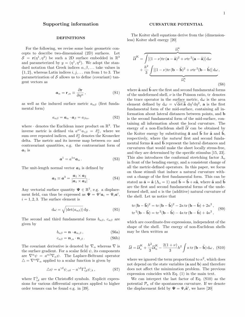
1
Supporting information
DEFINITIONS
For the following, we revise some basic geometric con-cepts to describe two-dimensional (2D) surfaces. LetS = r(η1, η2) be such a 2D surface embedded in R3
and parameterized by y = (η1, η2). We adopt the stan-dard notation that Greek indices α, β, . . . take values in{1, 2}, whereas Latin indices i, j, . . . run from 1 to 3. Theparametrization of S allows us to define (covariant) tan-gent vectors as
aα = r,α ≡∂r
∂ηα, (S1)
as well as the induced surface metric aαβ (first funda-mental form)
aαβ = aα · aβ = aβα, (S2)
where · denotes the Euclidean inner product on R3. Theinverse metric is defined via aαγaγβ = δαβ , where wesum over repeated indices, and δαβ denotes the Kroneckerdelta. The metric and its inverse map between co- andcontravariant quantities, e.g. the contravariant form ofa1 is
a1 = a1αaα . (S3)
The unit-length normal vector a3 is defined by
a3 ≡ a3 =a1 × a2
|a1 × a2|. (S4)
Any vectorial surface quantity Ψ ∈ R3, e.g. a displace-ment field, can thus be expressed as Ψ = Ψiai = Ψia
i,i = 1, 2, 3. The surface element is
dω =√|det(aαβ)|dy . (S5)
The second and third fundamental forms bαβ , cαβ aregiven by
bαβ = n · aα,β , (S6a)
cαβ = n,α · n,β . (S6b)
The covariant derivative is denoted by ∇α whereas ∇ isthe surface gradient. For a scalar field ψ, its componentsare ∇αψ = aαβ∇αψ. The Laplace-Beltrami operator4 = ∇α∇α applied to a scalar function is given by
4ψ = aγδψ,γδ − aγδΓλγδψ,λ , (S7)
where Γλγδ are the Christoffel symbols. Explicit expres-sions for various differential operators applied to higherorder tensors can be found e.g. in [39].
CURVATURE POTENTIAL
The Koiter shell equations derive from the (dimension-less) Koiter shell energy [20]
UK=
UKs︷ ︸︸ ︷∫
[(1− ν)tr (a− ◦a)2 + νtr 2(a− ◦
a)] dω
+h2
3
∫[(1− ν)tr (b−
◦b)2 + νtr 2(b−
◦b)] dω︸ ︷︷ ︸
UKb
,
(S8)
where◦a and
◦b are the first and second fundamental forms
of the undeformed shell, ν is the Poisson ratio, tr denotesthe trace operator in the surface metric, dω is the areaelement defined by dω =
√det
◦a dη1dη2, a is the first
fundamental form of the mid-surface, containing all in-formation about lateral distances between points, and bis the second fundamental form of the mid-surface, con-taining all information about the local curvature. Theenergy of a non-Euclidean shell U can be obtained by
the Koiter energy by substituting a and b for◦a and
◦b,
respectively, where the natural first and second funda-mental forms a and b represent the lateral distances andcurvatures that would make the sheet locally stress-free,and they are determined by the specific stimulus [15, 23].This also introduces the conformal stretching factor Λo
in front of the bending energy, and a consistent change ofall the metric-defined operators. In this paper, we focuson those stimuli that induce a natural curvature with-out a change of the first fundamental form. This can be
stated as a =◦a (Λo = 1) and b =
◦b +κ
◦a, where
◦a and
◦b
are the first and second fundamental forms of the unde-formed shell, and κ is the (additive) natural curvature ofthe shell. Let us notice that
tr (b− b)2 = tr (b−◦b)2 − 2κ tr (b−
◦b) + 2κ2 ,
tr 2(b− b) = tr 2(b−◦b)− 4κ tr (b−
◦b) + 4κ2 ,
(S9)
which are coordinate-free expressions, independent of theshape of the shell. The energy of non-Euclidean shellsmay be then written as
U = UK
s +h2
3UK
b −2(1 + ν)
3h2∫κ tr (b−
◦b) dω , (S10)
where we ignored the term proportional to κ2, which doesnot depend on the state variables (a and b) and thereforedoes not affect the minimization problem. The previousexpression coincides with Eq. (1) in the main text.
We can interpret the last factor of Eq. (S10) as thepotential Pκ of the spontaneous curvature. If we denotethe displacement field by Ψ = Ψi
◦ai, we have [20]

2
tr (b−◦b) = 4Ψ3−◦
cααΨ3+2◦bβσ∇βΨσ+∇α
◦bταΨτ+O(|Ψ|2) ,
(S11)where
◦c is the third fundamental form of the unde-
formed surface. The trace of the third fundamental formis tr
◦c =
◦cαα = 4
◦H2−2
◦K, where
◦H and
◦K are the mean and
the Gaussian curvatures of the undeformed mid-surface,respectively [39]. For a homogeneous κ, if we substituteEq. (S11) into Eq. (S10) and use the Leibniz rule, we getfor the curvature potential
Pκ = −2(1 + ν)
3h2κ
∫[4Ψ3 − ◦
cααΨ3 +∇β(◦bβσΨσ)
+◦bβσ∇βΨσ] dω .
(S12)By applying the generalized Stokes theorem to the termsin divergence form, we obtain generalized bulk andboundary work terms:
Wedge =2(1 + ν)
3h2κ
∮q · t ds ,
Wbulk =2(1 + ν)
3h2κ
∫◦bβσ∇βΨσ − ◦
cααΨ3 dω ,
(S13)
where · denotes the inner product in the surface metric,t is the unit tangent vector to the surface, perpendicularto the boundary curve, and q is the rotation vector. Forsmall displacements (= O(h)), the rotation of a covari-ant vector
◦aα is qα = δ
◦aα · ◦
a3, where δ denotes a smallincrement (Figure S1), therefore one can also define therotation vector as
q = (δ◦aα · ◦
a3)◦aα = −(δ
◦a3 · ◦
aα)◦aα = ∇Ψ3 +
◦bΨ . (S14)
By introducing the characteristic length of the boundarycurve l, radius of curvature R and area of the shell A,we can generalize the scalings presented in the maintext, and show that Wedge ∼ h2κ2 l
√Rh and Wbulk ∼
h4κ2R−2A, where we have used that for near isometries,|Ψ| < Ψ3. The scalings of the generalized work termssuggest that the boundary work prevails over the bulkwork for open shells, regardless of the shape of the mid-
surface. For surfaces with ∇α◦bτα = 0, such as plates,
cylinders, and spheres, among others, the work termscan be reworked as
Wedge =2(1 + ν)
3h2κ
∮(q +
◦bΨ) · t ds ,
Wbulk = −2(1 + ν)
3h2κ
∫◦cααΨ3 dω ,
(S15)
where now the boundary work suggests a combinedtorque and membrane force at the boundary, while thebulk work suggests an effective pressure in the bulk.
R
θ
◦a3
B
N
◦a3 + δ
◦a3
t t+ δt
FIG. S1. Axisymmetric profile of the shell with variationsof the normal and the unit tangent vector on the boundarycurve.
✓R
⇠ ✓p
Rh ⇠
1/b11
R
✓
FIG. S2. A spherical shell at snapping, the observation thatits tangent plane on the boundary curve is horizontal suggeststhe scaling analysis (left). Self-similar profiles of shells beforesnap-through instabilities (right).
Scaling of |q− Ψ/R|
As the boundary layer is bending dominated, we
have tr (b −◦b) ∼ κ. Since tr (b −
◦b) = ∇α(∇αΨ3 −
2Ψα/R) − 2Ψ3/R2 ∼ |q − Ψ/R|/
√Rh, we conclude
that |q− Ψ/R| ∼ κ√Rh.
SNAPPING OF OPEN SHELLS
Scaling
The experimental observation that shells with θ < π/2snap when the tangent plane on the boundary curve ishorizontal leads to the scaling law represented by Eq.(3) in the main text, which we derive here in more detailwith reference to Figure S2. At snapping, the tangentplane on the boundary curve is horizontal meaning thatthe covariant vector a1 is horizontal. If we want to es-timate the characteristic curvature within the boundarylayer with a width scaling as
√Rh, we have to estimate
the characteristic variation of the angle between a1 andthe horizontal axis. Indeed, a1 rotates by an amountproportional to θ from the beginning of the boundary

3
0 1 2 3 4
0
2
4
1 + ν
1
κR
b1 1R,b2 2R
FIG. S3. Longitudinal (b11, blue symbols) and meridional(b22, red symbols) curvature within the boundary layer be-fore snapping, at different locations and for different geome-tries, for different values of h/R ∈ [0.001, 0.1]. The solid blackline represents Eq. (S17) whereas symbols represent numericalsimulations.
layer up to the boundary curve. Consequently, we canestimate the characteristic curvature as θ/
√Rh. At the
same time, we can estimate this curvature via a min-imization of the energy in this state, assuming that itis bending-dominated [27] and almost flat (|b22| � |b11|).With these two assumptions, the Euler-Lagrange equa-tions associated with the bending energy read
2[b11 −
(− 1
R+ κ)]
+ 2ν[b22 −
(− 1
R+ κ)]− λb22 = 0 ,
2ν[b11 −
(− 1
R+ κ)]
+ 2[b22 −
(− 1
R+ κ)]− λb11 = 0 ,
(S16)where λ is the Lagrange multiplier enforcing the con-straint of a null Gaussian curvature, b11 and b22 are thecurvatures along the colatitude and azimuthal directionsin the boundary layer, respectively. Using the assump-tion b22 ' 0, we get λ = 2(ν − 1) and
b11 ' (1 + ν)(−1/R+ κs) , (S17)
which nicely agrees with numerical results as shown infigure S3. If we combine the two scalings we get Eq. (3)in the main text
(1 + ν)(−1/R+ κs) ∼θ√Rh⇒ κsR = βθ − α , (S18)
where θ = θ/√h/R, ν = 1/2, and α and β are two
unknown parameters that have to be determined numer-ically.
1D model and 2D model
As the deformation up to the snap-through instabil-ity is experimentally observed to be axially symmet-
ric, we derive a 1D model in which the energy of theshell is minimized in the profile curve of the shape. Wewrite the parametrization of the profile curve as η1 7→(φ(η1), ψ(η1)), such that when κ = 0 we have φ(η1) =R sin η1 and ψ(η1) = R cos η1 with η1 ∈ [0, θ]. We thenderive the first and second fundamental forms as [15]
a =
(φ2u + ψ2
u 00 φ2
),
b =1√
φ2u + ψ2u
(ψuuφu − φuuψu 0
0 φψu
).
(S19)
If we substitute these expressions in the energy of theshell, we obtain a second order functional of φ and ψ, andwe reduce it to a first order functional with the changeof variable Ψu = φuζ [15]. For symmetry we requirethat φ(0) = ζ(0) = 0 and ψ(0) = R, ∀κ. We minimizethe first order functional in COMSOL Multiphysics witha custom arc-length method to vary κ.
The numerical results confirm the scaling law κsR =βθ − α, with α = 0.67 and β = 0.85. The prominentrole of geometry throughout this analysis leads to theself-similarity shown in Figure S2 (right), where shellspossessing the same values of h/R, θ, and κR have similarshapes that collapse onto a single one upon the affinetransformation of uniform scaling by 1/R.
In the 2D model, we minimize the energy of the shellvia a C1-continuous subdivision finite elements (SD-FEs) [40].
BUCKLING OF OPEN SHELLS
Let us now focus on the buckling of open shellswith particular emphasis on the two diverging regimes.For θ → 0 we derived κbR = ±a/θ2 + 1 , from the flatcase presented in [17], assuming the radius of the plateto be equal to Rθ. When θ → π, we estimated a diver-gence of the critical curvature as 1/(θ−π). We representthe critical buckling curvature as a function of θ in Fig-ure S4, where symbols denote 2D simulations, and colorsdenote different values of h/R. The diverging behaviorfor θ → 0 is very well captured by our scaling and is uni-versal as well as the divergence for θ → π, although thelatter does not rely on an analytically solved plate prob-lem. The scalar coefficients in Eq. (4) in the main textare determined numerically as b ' 3.6 and c ' −0.98.
BUCKLING OF CLOSED SHELLS
Fundamental solution
Deformations preserving the spherical symmetry sat-isfy Ψ1 = Ψ2 = 0. Therefore, we can express the linear

4
0 π/6 π/3 π/2 23π
56π
π−4
−3
−2
−1
0
θ
κbR
FIG. S4. Critical buckling curvature versus θ. Circles ingreen, red, blue, black, and orange denote 2D simulationsfor h/R = 0.01, 0.018, 0.02, 0.022, 0.04, respectively, whileblack solid lines represent Eq. (4).
stretching and bending strains as [20]
tr 2(a− ◦a) =
16
R2Ψ2
3 , tr (a− ◦a)2 =
8
R2Ψ2
3 ,
tr 2(b−◦b) =
4
R4Ψ2
3 , tr (b−◦b)2 =
2
R4Ψ2
3 ,
(S20)
so that the Euler-Lagrange equation for Ψ3 is
4
R2(1+ν)
(4+
1
3
( hR
)2)Ψ3+
4
3(1+ν)
( hR
)2κ = 0 , (S21)
which gives the result of the main text
Ψ3 = −R2
12
(h/R)2
1 + (1/12)(h/R)2κ = −h
2
12κ+O((h/R)4) .
(S22)This expression is consistent with that obtained in thecase of pressure buckling [32] via the analogy presentedvia Eq. (5) in the main text. Indeed, if we substituteEq. (5) in Eq. (S22), we find
Ψ3 = −(1− ν)pR2
2Eh. (S23)
This configuration of the shell is called fundamental state.
Stability analysis
While the analogy between spontaneous curvature andpressure allows for a better understanding of the spon-taneous curvature and for a simple determination of thefundamental state, it does not adequately describe theresidual stress that develops within the shell. Indeed,while the residual stress developed within a pressurizedthin shell is of the membrane type (residual bending mo-ments are negligible), a spontaneous curvature modifies
the bending ground state leading to residual bending mo-ments that have the same order of magnitude of the resid-ual membrane stress.
To determine the critical spontaneous curvature lead-ing to buckling, we have to enrich the procedure pre-sented by Koiter [42] to take into account the residualbending moments. We therefore write the quadratic en-ergy functional as
P2[Ψ;κ] =
∫Eh
2(1− ν2)
[(1− ν)GαβGαβ + ν(Gαα)2
+h2
12[(1− ν)ραβραβ + ν(ραα)2]
]+Nαβγαβ
+Mαβζαβ dω ,(S24)
where Gαβ and ραβ represent the linear stretching andbending strains with respect to the fundamental state,Ψ is here the displacement field from the fundamentalstate, γαβ and ζαβ are the nonlinear second order stretch-ing and bending strains with respect to the fundamentalstate. The term in the last line represents the contribu-tion of the bending moments in the fundamental stateto the energy functional, which is neglected in the classi-cal pressure buckling problem because of the absence ofinelastic stimuli that change the ground state.
We now report the expressions for the linear and non-linear (second order) strains, and evaluate Mαβζαβ . Lin-ear stretching and bending strains can be written as [20]
Gαβ =1
2(∇βΨα +∇αΨβ) +
Ψ3
R◦aαβ ,
ραβ = ∇αβΨ3 −1
R2
◦aαβΨ3 −
1
R(∇βΨα +∇αΨβ) ,
(S25)where the first and second fundamental forms in the fun-damental state can be approximated with those in theundeformed state, since the displacement from the un-deformed to the fundamental state is smaller than thethickness [42]. The nonlinear (second order) stretchingstrain is
γαβ =1
2∇λΨα∇λΨβ +
1
2RΨ3∇βΨα +
1
2RΨ3∇αΨβ
+1
2R2
◦aαβΨ2
3 +1
2∇αΨ3∇βΨ3 −
1
RΨα∇βΨ3
+1
2R2ΨαΨβ .
(S26)As regards the nonlinear (second order) bending strain,the expression is rather lengthy. However, we shall seethat only their trace is needed for the analysis. Indeed,we compute the bending moments in the fundamentalstate as
Mαβ =Eh3
12(1 + ν)
( ν
1− ν◦aαβ
◦aγδ +
◦aαγ
◦aβδ)
(bγδ|f − bγδ) ,(S27)

5
where bγδ|f denotes the second fundamental form inthe fundamental state. Combining Eq. (S22) withstrains (S25) arising from a displacement from the un-deformed to the fundamental state, we get
bγδ|f − bγδ = −(− 1
12
( hR
)2+ 1)κ
◦aγδ ' −κ◦
aγδ , (S28)
where the last approximation is consistent within a the-ory for thin shells. Therefore, the bending moments inthe fundamental state are
Mαβ = − Eh3
12(1− ν)κ
◦aαβ , (S29)
and its contraction in (S24) with the bending strainstherefore amounts to taking the trace of ζαβ . From [39],for a spherical surface we have
◦aαβζαβ =
1
R2Ψα∇αΨ3 −
1
R|∇Ψ3|2
+1
RΨα4Ψα −∇αΨ34Ψα .
(S30)
In order to express Mαβζαβ in a convenient way, we recallthat the tangential displacement can always be expressedin terms of two invariants [41, 42]
Ψα = ∇αφ+ εαλ∇λψ , (S31)
where φ and ψ can be regarded as potentials, and εαλ isthe two-dimensional Levi-Civita symbol. The advantageof writing the in-plane displacement via the two poten-tials fields is that the balance equations will be decoupledin φ and ψ.
Let us start with the first term in Eq. (S30):
1
R2
∫Ψα∇αΨ3 dω =
1
R2
∫∇α(ΨαΨ3)−4φΨ3 dω =
= − 1
R2
∫4φΨ3 dω ,
(S32)where we used the generalized Stokes theorem on a closedsurface and ∇αΨα = 4φ, since ∇αβψ is symmetric. Asregards the second term in Eq. (S30)
− 1
R
∫|∇Ψ3|2 dω = − 1
R
∫∇α(∇αΨ3)−Ψ34Ψ3 dω =
=1
R
∫Ψ34Ψ3 dω ,
(S33)again by using the generalized Stokes theorem on a closedsurface. For the third term in Eq. (S30) we have
1
R
∫Ψα4Ψα dω =
1
R
∫∇αφ∇αβ··βφ+ εαλ∇λψ∇αβ··βφ
+∇αφεαγ∇γ·β·β ψ + εαγ∇γψεαλ∇λβ··βψ dω .
(S34)
Following the procedure in [42], the second and thirdin (S34) terms are zero, whereas the first term can besimplified as
1
R
∫∇αφ∇αβ··βφdω = − 1
R
∫ ((4φ)2 +
4φR2
φ)
dω .
(S35)Analogously, the fourth term can be rewritten as
1
R
∫εαγ∇γψεαλ∇λβ··βψ dω = − 1
R
∫ ((4ψ)2 +
4ψR2
ψ)
dω ,
(S36)by applying the generalized Stokes theorem. Finally, forthe fourth term in Eq. (S30) we find
−∫∇αΨ34Ψα dω =
∫∇αβΨ3∇αβφ dω =
=
∫4φ(4Ψ3 +
Ψ3
R2
)dω .
(S37)
Using these simplifications, the contribution of the bend-ing moments in the fundamental state becomes∫
Mαβζαβ dω = − Eh2
12(1− ν)κh
∫1
RΨ34Ψ3 +4φ4Ψ3
− (4φ)2
R− 4φR3
φ− (4ψ)2
R− 4ψR3
ψ dω .
(S38)We shall show that the terms in the second line can beneglected. To do so, we express Koiter’s result on thecontribution of the membrane stress in the fundamentalstate in the case of a natural curvature via the analogypresented in the main text as∫
Nαβγαβ dω = − Eh2
24(1− ν)Rκh
∫(4φ)2 + 4
Ψ3
R4φ
−Ψ34Ψ3 +2
R2Ψ2
3 + (4ψ)2 dω ,
(S39)where we also took into account the different conven-tion used by Koiter about the orientation of the normal.We recall now that Koiter neglected all terms in the lastfunctional except Ψ34Ψ3 by comparing them with thesimilar ones in the elastic energy and showing that theyare smaller by at least a factor h/R. Now, since theterms proportional to (4φ)2 and (4ψ)2 in Eq. (S38) havesmaller pre-factors than those in Eq. (S39), which Koi-ter neglected, can be neglected. Moreover, Koiter alsoneglected the following term arising from the membraneprestress
Eh√3(1− ν2)R2
h
R
∫φ4φ+ ψ4ψ dω ,
which are comparable to the similar terms in Eq. (S38),which we can therefore neglect. Finally, the contributionof the bending moments in the fundamental state has

6
been reduced to∫Mαβζαβ dω = − Eh2
12(1− ν)κh
∫1
RΨ34Ψ3+4φ4Ψ3 dω ,
(S40)while the contribution of the membrane stress has beenreduced to∫
Nαβγαβ dω =Eh2
24(1− ν)Rκh
∫Ψ34Ψ3 dω . (S41)
Furthermore, 4ψ = 0 [42], such that we finally obtain
P2[Ψ;κ] =Eh
2(1− ν2)
∫(4φ)2 +
1− νR2
φ4φ
+2(1 + ν)
RΨ34φ+
2(1 + ν)
R2Ψ2
3 +h2
12(4Ψ3)2
− 1 + ν
12
h
RκhΨ34Ψ3 −
(1 + ν)h2
6κ4φ4Ψ3 dω .
(S42)The resulting balance equations obtained via a first vari-ation are
42φ+1− νR24φ+
1 + ν
R4Ψ3 −
1 + ν
12h2κ42Ψ3 = 0 ,
h2
1242Ψ3 −
1 + ν
12
h
Rκh4Ψ3 + 2
1 + ν
R2Ψ3 +
1 + ν
R4φ
− 1 + ν
12h2κ42φ = 0 .
(S43)The standard procedure is now to expand φ and Ψ3 inspherical harmonics
φ(ηα) = R
∞∑n=0
DnSn(ηα) , Ψ3(ηα) =
∞∑n=0
CnSn(ηα) ,
(S44)which allows to express the system (S43) as
−[1 + ν +
1 + ν
12
h
Rκhx
]Cn + [x− (1− ν)]Dn = 0 ,[ 1
12
( hR
)2x2 +
1 + ν
12
h
Rκhx+ 2(1 + ν)
]Cn
− (1 + ν)[x+
1
12
h
Rκhx2
]Dn = 0 ,
(S45)where x = n(n+1). The system (S45) has nontrivial solu-tions only if the determinant vanishes. As in the classicalpressure buckling, the buckling mode has a short wave-length compared to the radius of the sphere, e.g. x� 1,and the condition for nontrivial solutions reads
κh = 2R
h
−3(1 + 2ν) +√
3(15 + (h/R)2x2 + 12ν)
(1 + ν)x.
(S46)We now look for the minimum value of the critical κh,
which will be the buckling spontaneous curvature. Todo so, as x � 1, we regard it as a real number andminimize (S46) with respect to x to get
x =2
1 + 2ν
R
h
√3(5 + 4ν)(1− ν2) , (S47)
0 500 1000 1500 2000
1
1.5
2
2.5
3
R/h
4√7
n(n+ 1)
κh
FIG. S5. Critical buckling curvature versus n(n + 1)for ν = 1/2.
which yields Eq. (6) of the main text
κbh = 4
√3
1− ν(1 + ν)(5 + 4ν)
, (S48)
which for an incompressible material becomes
κbh =4√7. (S49)
Finally, as usually done in standard buckling problemsin mechanics, we plot Eq. (S46) as a function of x fordifferent values of h/R in figure S5.
SIMULATIONS ON ELLIPSOIDAL SHELLS
To show how the curvature potential can be useful tostudy also the morphing of shells with non homogenoeuscurvatures, we performed numerical simulations onellipsoidal shells (minor radii r1 = r2 = R, major radiusr3 = 3/2R, h/R = 0.04, opening angle θ = π/2), in thetwo cases of negative and positive natural curvature.
0 28eba. b. c. d.
FIG. S6. Simulations on the curvature-induced instabilitiesin ellipsoidal shells. The undeformed shape is reported inb. When the natural curvature is negative, the shell bucklesinto the shape shown in a., whereas the shell snaps when thenatural curvature is positive, as reported in c. and d. Colordenotes total bending energy density eb, i.e. the last twoterms of Eq. S10.

7
The results are reported in figure S6, where b. denotesthe undeformed shape. When the natural curvatureis negative, the shell buckles into the shape shownin a., similarly to the buckling of a spherical shellinto a spindle-like shape. On the contrary, when thenatural curvature is positive, the shell snaps (c. and
d.). In particular, figure S6 (c.) shows that most ofthe deformation is focused in the boundary layer, inagreement to what the mechanical interpretation andscalings of the curvature potential for arbitrary openshells show.


![Discrete Quadratic Curvature Energies - Columbia University · ing energies that govern the mechanics of elastic thin plates and shells [14,47]; geometry processing operations such](https://img.pdfslide.us/doc/110x75/5f6ccc607bd4184e691dbb05/discrete-quadratic-curvature-energies-columbia-ing-energies-that-govern-the-mechanics.jpg)