Embed Size (px)
Citation preview
CURRIES Shop ManualRevised 03/15
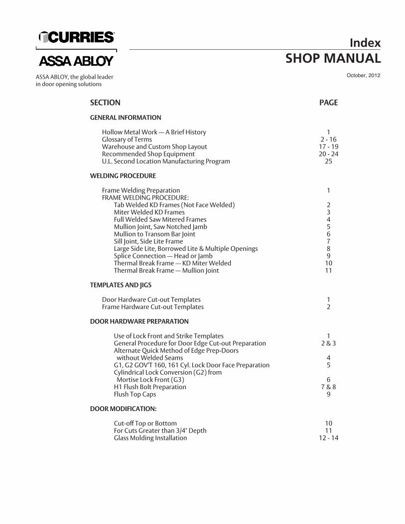
SECTION PAGE
GENERAL INFORMATION
Hollow Metal Work — A Brief History 1Glossary of Terms 2 - 16Warehouse and Custom Shop Layout 17 - 19Recommended Shop Equipment 20 - 24U.L. Second Location Manufacturing Program 25
WELDING PROCEDURE
Frame Welding Preparation 1FRAME WELDING PROCEDURE:
Tab Welded KD Frames (Not Face Welded) 2Miter Welded KD Frames 3Full Welded Saw Mitered Frames 4Mullion Joint, Saw Notched Jamb 5Mullion to Transom Bar Joint 6Sill Joint, Side Lite Frame 7Large Side Lite, Borrowed Lite & Multiple Openings 8Splice Connection — Head or Jamb 9Thermal Break Frame — KD Miter Welded 10Thermal Break Frame — Mullion Joint 11
TEMPLATES AND JIGS
Door Hardware Cut-out Templates 1Frame Hardware Cut-out Templates 2
DOOR HARDWARE PREPARATION
Use of Lock Front and Strike Templates 1General Procedure for Door Edge Cut-out Preparation 2 & 3Alternate Quick Method of Edge Prep-Doorswithout Welded Seams 4G1, G2 GOV’T 160, 161 Cyl. Lock Door Face Preparation 5Cylindrical Lock Conversion (G2) from Mortise Lock Front (G3) 6H1 Flush Bolt Preparation 7 & 8Flush Top Caps 9
DOOR MODIFICATION:
Cut-off Top or Bottom 10For Cuts Greater than 3/4" Depth 11Glass Molding Installation 12 - 14
IndexSHOP MANUAL
October, 2012ASSA ABLOY, the global leaderin door opening solutions
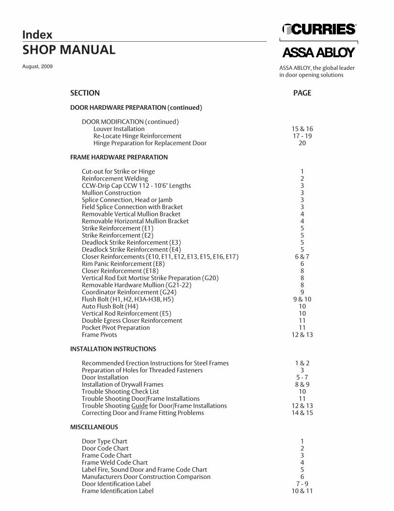
SECTION PAGE
DOOR HARDWARE PREPARATION (continued)
DOOR MODIFICATION (continued)Louver Installation 15 & 16Re-Locate Hinge Reinforcement 17 - 19Hinge Preparation for Replacement Door 20
FRAME HARDWARE PREPARATION
Cut-out for Strike or Hinge 1Reinforcement Welding 2CCW-Drip Cap CCW 112 - 10'6" Lengths 3Mullion Construction 3Splice Connection, Head or Jamb 3Field Splice Connection with Bracket 3Removable Vertical Mullion Bracket 4Removable Horizontal Mullion Bracket 4Strike Reinforcement (E1) 5Strike Reinforcement (E2) 5Deadlock Strike Reinforcement (E3) 5Deadlock Strike Reinforcement (E4) 5Closer Reinforcements (E10, E11, E12, E13, E15, E16, E17) 6 & 7Rim Panic Reinforcement (E8) 6Closer Reinforcement (E18) 8Vertical Rod Exit Mortise Strike Preparation (G20) 8Removable Hardware Mullion (G21-22) 8Coordinator Reinforcement (G24) 9Flush Bolt (H1, H2, H3A-H3B, H5) 9 & 10Auto Flush Bolt (H4) 10Vertical Rod Reinforcement (E5) 10Double Egress Closer Reinforcement 11Pocket Pivot Preparation 11Frame Pivots 12 & 13
INSTALLATION INSTRUCTIONS
Recommended Erection Instructions for Steel Frames 1 & 2Preparation of Holes for Threaded Fasteners 3Door Installation 5 - 7Installation of Drywall Frames 8 & 9Trouble Shooting Check List 10Trouble Shooting Door/Frame Installations 11Trouble Shooting Guide for Door/Frame Installations 12 & 13Correcting Door and Frame Fitting Problems 14 & 15
MISCELLANEOUS
Door Type Chart 1Door Code Chart 2Frame Code Chart 3Frame Weld Code Chart 4Label Fire, Sound Door and Frame Code Chart 5Manufacturers Door Construction Comparison 6Door Identification Label 7 - 9Frame Identification Label 10 & 11
IndexSHOP MANUALAugust, 2009 ASSA ABLOY, the global leader
in door opening solutions
Hollow metal work was introduced into the building and construction industry early inthe Twentieth Century according to records indicating it’s beginning in the Jamestown,New York area. Emphasis for this new development was motivated by the great fires inBaltimore and San Francisco in an attempt to reduce the flammability of wood construc-tion.
Initially, doors and frames were constructed of wood with thin gauge metal encasementto deter flammability. Further development resulted in basic self supporting steel doors,eliminating the wood core. This was introduced by the Dahlstrom Metallic DoorCompany in their catalog of 1909. Other 1909 catalogs showed stile and rail hollowmetal doors with no structural wood core and incorporating glass or metal panels.
The first steel frames appeared in the Dahlstrom catalog in 1915 as “Special Frames forHospital Doors”. These were of 12 gauge and 16 gauge formed steel with faces fittingflush with the wall surface. Wood trim could be applied if desired. A few other manufac-turers, in 1915, offered press formed steel frames, but generally the three piece framewith separately applied trim was still predominant.
Both doors and frames were prepared for hardware from templates and the range of trimstyles covered a great many ornate designs. One manufacturer, for example offered 200different design options. By comparison, with the era of standardization we have today,this design freedom has given way to the standard 2" wide face frame.
The origin of the flush hollow metal door is believed to be around 1915 when again theDahlstrom Catalog offered a door with no recessed panels. It was not until 1930 that theuse of Z-BAR, channel and truss cores appeared as relatively standard methods of sup-porting door “skins” or face sheets. These methods were enhanced with the growingdevelopment of electrical arc and spot welding.
The building boom following World War II prompted the introduction of stock steeldoors and frames, with their usage steadily increasing until today when they havebecome generally accepted in place of wood products for their fire resistance as well asappearance, strength and durability. Also the ecological need for wood conservation aswell as the continual development of electronically controlled manufacturing equipmenthave enhanced the usage of steel and hollow metal products giving the architect anincreasingly wider variety of design options.
REFERENCE: National Association of Architectural Metal Manufacturers“Hollow Metal Technical and Design Manual”
1
Hollow Metal Work - A Brief HistorySHOP MANUAL
August, 2009ASSA ABLOY, the global leaderin door opening solutions
Definitions of common terms pertainingto Hollow Metal Doors and Frames
NOTE: Similar Terminology noted in parenthesis below Term
ACTIVE DOOR(Active Leaf)
ANCHOR
Adjustable Base Anchor(Floor Strut)(Floor Stilt)
Base Anchor(Floor Anchor)(Base Clip)
Base Anchor Extension(Floor Anchor Extension)
Existing Opening Anchor
Jamb Anchor
ANTI-PANIC HARDWARE
ASTRAGAL
Mortised Astragal
Overlapping Astragal
The first operating door of a pair; usually that one in which a lock, if any,is installed.
A device used to anchor frame to surrounding structure.
An adjustable device used to hold frames above a finished floor.
Metal piece attached to base of frame to secure frame to the floor,either fixed or adjustable.
Metal angle attached to the base of a frame with the horizontal legextending beyond the frame back bend. Used to facilitate the use ofpower tools in attachment of frame to floor.
Metal piece inside throat of frame for reinforcing when frame issecured in an existing wall using screws and expansion shields.
Metal device inserted in or attached to the back of a frame jamb toanchor frame to the wall.
Masonry: Used in masonry walls.Stud: Used with steel or wood stud walls.
See Panic Hardware.
A member or combination of members applied to one or both doorsof a pair at their meeting edges to close the clearance gap for thepurpose of providing either a weather seal, minimizing the passageof light or retarding the passage of smoke or flame during a fire.
A two-piece astragal having one part recessed in the edge of each door.
A one piece astragal attached to one door only and overlapping theother door when in the closed position.
2
Glossary of TermsSHOP MANUALAugust, 2009 ASSA ABLOY, the global leader
in door opening solutions
ASTRAGAL (continued)
Split Astragal
BACKBEND(Backband)(Return)
BACKBEND RETURN
BACKSETFlush Bolt Backset
Hinge Backset
Lock Backset
Strike Backset
BASE(Sill)
BASE ANCHOR EXTENSION
BEVELED EDGE
BEVELED SQUARE EDGE
BLANK JAMB
BORROWED LITE (Light)
BOTTOM ARM
BOTTOM RAIL
A two-piece astragal, one piece of which is surface mounted oneach door and provided with a means of adjustment to abutt theother piece and provide a seal.
The return face to the wall, at the outer edge of frame trim orface.
Turned in edge of backbend of frame.
Distance from vertical centerline of leading edge of a door to thecenterline of the bolt.
On a door, the distance from the stop face, or narrow side to the edge of the hinge cut-out. On a frame, the distance from thestop to the edge of the hinge cutout.
The distance from the vertical centerline of the leading edge of adoor to the centerline of the lock cylinder, measured horizontallyand parallel to the door face.
On a door frame, the distance from the stop to the edge of thestrike cut-out.
That member of a sidelite frame which extends along the floor toform a base.
See Anchor.
Edge of a door which is beveled (standard 1/8 inch in 2 inches) toprovide clearance with strike jamb or adjacent door of a pair ofdoors as the door is closed.
Edge of a door which is beveled only at the corners for clearancein swinging. The center portion of the edge is at a 90 degree angleto the door face for lock mortising.
See Jamb.
A window frame for use in an interior partition.
The arm mechanism attached to the bottom rail of a door andconnected to the spindle of the door closer or pivot.
Horizontal rail at the bottom of a door connecting lock stile to the hinge stile.
3
Glossary of TermsSHOP MANUAL
August, 2009ASSA ABLOY, the global leaderin door opening solutions
BULL NOSE EDGE
BULL NOSE TRIM
BUTT
BUTT HINGE
BUTT-HUNG DOOR
BUTTED FRAME
CABINET JAMB
CASED OPENING
CEILING STRUT
CENTER-HUNG DOOR
CENTER PANEL
CENTER PIVOT
CENTER RAIL
CHECK
CLOSER
CLOSER REINFORCING
Corner Bracket
Edge of a door with a large radius to provide clearance for swinging inboth directions.
The face of a jamb having a least a 1/4" radius rather than a sharp 90degree bend at the edge next to the door opening.
Abbreviation for a Butt Hinge.
A type of hinge which has rectangular leaves, usually of thesame size, and multiple bearing contacts.
A door hung on butt hinges.
A frame which fits against the wall structure rather than around it.Frame depth is normally equal to or less than the wall thickness.
Frame in three or more pieces applied as the finished frame over a rough buck.
An interior wall opening which has a frame with trim but nostops and contains no door or window.
An adjustable frame member extending vertically from the head ofa door frame to a rigid support above to hold the frame in place.
A door hung on center pivots.
Portion of a door between hinge and lock stile.
Swing door hardware having its pivot axis on the thicknesscenterline of the door and normally located about 2 3/4" from thehinge jamb.
Horizontal rail in a door usually located at lock height used to separateupper and lower panels of a recessed panel type door.
See Door Closer.
See Door Closer.
A metal plate reinforcement in a door or a door frame to provide additional strength for the attachment of a door closer.
Bracket connected to door frame jamb and head at upper hinge corner to support exposed overhead closer. Used on out swingingdoors only.
4
Glossary of TermsSHOP MANUALAugust, 2009 ASSA ABLOY, the global leader
in door opening solutions
CLOSER REINFORCING (continued)Full Sleeve
Half Sleeve
COMMUNICATING FRAME
COMPLETED OPENING ANCHOR
COMPOSITE METAL FACE CONSTRUCTION
COORDINATOR
CORE
CORNER REINFORCEMENT
CORNER POST
COVEMOLD FRAME
COVER PLATE
CRASH BAR(Panic Bar)
CRASH BAR HOUSING
CUT-OFF STOP(Terminated Stop)(Hospital Stop)
CUT-OUT
Formed plate which reinforces soffit, rabbet and both faces of aframe.
Formed plate which reinforces soffit, one rabbet and one face of a frame.
A double rabbeted frame with both rabbets prepared for single swingdoors. Doors swing in opposite directions and may be of same or opposite hand.
See Anchor, Existing Opening.
A door constructed of a solid core bonded to a metal facing.
A mechanism which controls the order of closing of a pair of swingdoors; used with doors equipped with overlapping astragals and certain panic and fire exit hardware which requires one door to closeahead of the other.
The interior construction of a hollow metal door.
Reinforcing at junction of head and jamb used in interlocking ofknock-down (K.D.) or welded frames.
Vertical closed frame section used at the corner connection of two ormore frames mounted on adjacent perpendicular walls.
Frame having exposed contour faces simulating contour ofwood frame.
A finish plate used to cover the exposed face of either a floor closer notcovered by the threshold or a closer mounted in the head of a doorframe.
Cross bar of a fire exit hardware or panic hardware device, serving as apush bar to actuate the latch or latches.
Housing at either end of a crash bar which is mounted on the surface ofa door.
A door frame stop which terminates above the floor line and has aclosed end.
A preparation for hardware and/or accessories in a door or frame.
5
Glossary of TermsSHOP MANUAL
August, 2009ASSA ABLOY, the global leaderin door opening solutions
CYLINDRICAL LOCK PREPARATION
DEADLATCH
DEADLOCK
DOOR CLEARANCE
DOOR CLOSER(Check)(Closer)
DOOR LITE
DOOR OPENING
DOOR SIZE, ACTUAL
DOOR SIZE, NOMINAL
DOUBLE ACTING DOOR
DOUBLE ACTING FRAME
DOUBLE BEVELED EDGE
DOUBLE EGRESS FRAME
DOUBLE EGRESS MULLION
DOUBLE RABBET FRAME
DOUBLE SWING FRAME
Preparation in a door to accept a cylindrical lock.
A latch having an auxiliary feature which prevents its retraction by endpressure when in the projected position.
A lock in which a bolt is moved by means of a key or thumbturn, and ispositively stopped in its projected position.
The space between door and frame rabbet, between door and finishedfloor (see also Undercut), or between meeting edges of pairs of doors.
A device or mechanism to control the closing of a swing door; maybe overhead or floor mounted and either exposed or concealed.
The glass area in a glazed door.
The opening dimension of a doorway, measured between jamb rabbetsand from floor line to head rabbet. The opening size is usually the“nominal” door size, and is equal to the “actual” door size plus clearance and threshold height.
The actual size of the door leaf itself.
See Door Opening.
A door with hardware which permits it to swing to either side of theplane of its frame.
A frame prepared for one or two double acting doors.
An edge of a door beveled from the center toward eachface of the door.
A door frame prepared to receive two single-acting doors swingingin opposite directions, both doors being of the same hand.
Mullion used to divide pairs of doors in some types of double egressframes.
A frame having two rabbets on opposite sides of the stop.
A frame prepared to receive a pair of single-acting doors, both ofwhich swing in the same direction.
6
Glossary of TermsSHOP MANUALAugust, 2009 ASSA ABLOY, the global leader
in door opening solutions
DRYWALL FRAME
DUST COVER BOX
DUTCH DOOR
DUTCH DOOR FRAME
END CAP
END CHANNEL
FACE(Trim)
FILLER PLATE
FIRE EXIT HARDWARE
FIXED TRANSOM
FLOOR CLEARANCE
A knocked-down (K.D.) door frame designed for installation in a wallconstructed with studs and gypsum board or other dry sheet facingmaterial after the wall is erected.
A metal cover attached to a frame behind reinforcement for anymortised or recessed hardware, to prevent mortar or plaster fromentering the mounting holes.
A door consisting of two separate leaves, one above the other, whichmay be operated either independently or together, the lower leafusually having a service shelf at its top edge.
A frame prepared for a dutch door.
Inserted part used to provide flush condition on top and bottom ofa hollow metal door.
Horizontal channel welded into the top and bottom of a hollowmetal door for stiffening and rigidity.
Exposed part of a frame parallel to face of wall.
A metal plate used to fill unwanted mortise cut-outs in a door orframe (see also Hinge Filler).
An exterior door locking mechanism which is designed to be alwaysoperable from inside the building by pressure on a crash bar or lever,and which bears a U.L. label certifying its suitability for use on fire-rated emergency exit doors. Such hardware may be either:
a) Mortise type, having the lock mechanism mortised into the edge of the door or concealed within the door,
b) Rim type, having the lock mechanism mounted on the interior face of the door,
c) Vertical Rod type, surface or concealed, having the latches in or on the top and/or bottom of the door and activated by the crash bar through a rod linkage extending vertically on or in the lock stile of the door.
Panel or glass lite above door opening which is inoperable.
The width of the space between the bottom of a door andthe finished floor or threshold.
7
Glossary of TermsSHOP MANUAL
August, 2009ASSA ABLOY, the global leaderin door opening solutions
FLOOR CLOSER(Floor Check)(Floor Hinge)
FLOOR PIVOT
FLOOR STILT
FLOOR TO CEILING UNIT
FLUSH BOLT
FLUSH DOOR
FLUSH PANEL-TYPE DOOR(Stile and Panel Construction)
FLUSH PANEL-TYPE DOOR(Stile and Rail Construction)
GLASS STOP
GLAZING BEAD
A door-closing device which is installed in a recess in the floor belowthe door to regulate the opening and closing of a swing door.
A center or offset pivot located at the floor or threshold.
An anchoring device attached to a door frame jamb to holdthe bottom of the frame above the finished floor level.
An assembly with door and fixed panel above, no transom barbetween. Design of panel makes it appear to be extension of door.
A rod or bolt which is mounted flush with the edge or face of the inactivedoor of a pair, to lock the door to the frame at the head and/or sill. Whenmounted in the edge, operation is by means of a recessed lever. SeeSurface Bolt.
A door having flush surfaces, with no glass lights, louvers and grilles.
A type of door consisting of one center panel and one lock stile and onehinge stile. Stiles are butted against the panels the full length of thedoor horizontally stiffened with U-shaped end closures. Panels interlockwith the stiles, or are joined to the stiles by internal welding and arestiffened by a suitable method in accordance with the manufacturer’sstandard practice. Surface of panels and stiles lie in parallel planes, butpanels may be recessed an amount equal to the thickness of the stilemetal.
A type of door using stiles and rails either mitered or butted, the cornerjoints being welded and ground smooth. Panels interlock with the stilesand rails and are stiffened by internal reinforcing. Joint lines betweenthe panels,s tiles and rails may be left visible. Surface of panels and stileslie in a parallel plane. The panels may be recessed an amount equal tothe thickness of the stile metal.
A glazing bead which is either applied to, or is an integral part of, a window frame.
A formed metal section used to secure glass in a window opening.
8
Glossary of TermsSHOP MANUALAugust, 2009 ASSA ABLOY, the global leader
in door opening solutions
See Louver.
See Corner Reinforcement.
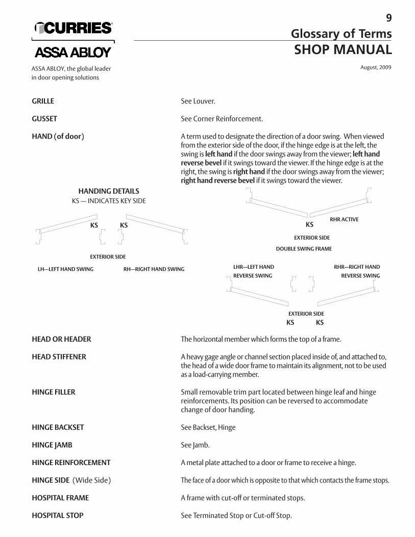
A term used to designate the direction of a door swing. When viewedfrom the exterior side of the door, if the hinge edge is at the left, theswing is left hand if the door swings away from the viewer; left handreverse bevel if it swings toward the viewer. If the hinge edge is at theright, the swing is right hand if the door swings away from the viewer;right hand reverse bevel if it swings toward the viewer.
The horizontal member which forms the top of a frame.
A heavy gage angle or channel section placed inside of, and attached to,the head of a wide door frame to maintain its alignment, not to be usedas a load-carrying member.
Small removable trim part located between hinge leaf and hingereinforcements. Its position can be reversed to accommodatechange of door handing.
See Backset, Hinge
See Jamb.
A metal plate attached to a door or frame to receive a hinge.
The face of a door which is opposite to that which contacts the frame stops.
A frame with cut-off or terminated stops.
See Terminated Stop or Cut-off Stop.
9
Glossary of TermsSHOP MANUAL
August, 2009ASSA ABLOY, the global leaderin door opening solutions
GRILLE
GUSSET
HAND (of door)
HEAD OR HEADER
HEAD STIFFENER
HINGE FILLER
HINGE BACKSET
HINGE JAMB
HINGE REINFORCEMENT
HINGE SIDE (Wide Side)
HOSPITAL FRAME
HOSPITAL STOP
HANDING DETAILSKS — INDICATES KEY SIDE
KS KS
KS KS
LH—LEFT HAND SWING RH—RIGHT HAND SWING LHR—LEFT HAND RHR—RIGHT HAND REVERSE SWING REVERSE SWING
KSRHR ACTIVE
DOUBLE SWING FRAMEEXTERIOR SIDE
EXTERIOR SIDE
EXTERIOR SIDE
INACTIVE DOOR OR LEAF
INTERCONNECTING FRAME
IMPOST
JAMB
Blank Jamb
Hinge Jamb
Strike Jamb
JAMB ANCHOR
JAMB DEPTH
JAMB EXTENSION
KEYED-IN-FRAME
KEY SIDE (of door)
KICKPLATE
KNOCKED DOWN
LABELED DOOR OR FRAME
LATCH
That leaf of a pair of doors which does not contain a lock but issecured, when closed, by top and bottom bolts and contains a striketo receive the latch or bolt of the active leaf.
See Communicating Frame.
See Mullion.
The vertical member forming the side of a frame.
A jamb which has not been prepared to receive hardware.
The jamb at which hinges or pivots are installed.
The jamb at the leading edge of a door, in which a strike may beinstalled.
See Anchor.
Overall outside dimension of frame section measured from face surfaceto face surface.
That section of a jamb which extends below the level of the finish floorfor attachment to the rough floor.
Frame erected with plaster or mortar forced behind frame backbend.Wall thickness is equal to or greater than frame throat, but no widerthan frame depth.
Side of door which receives the lock key.
A metal plate applied to the face of the lower rail of a door or sidelight to protect against abrasion or impact loads.
A term used in reference to any product that is shipped disassem-bled, for assembly at the building site: commonly abbreviated “KD”.
A door or frame that conforms to all applicable requirements, inrespect to fire resistance, of a nationally recognized testing authorityand bears its label designating the fire rating.
A hardware mechanism having a spring-activated beveled-end bolt, retractable by a knob or lever handle, but no lock-ing device; used to hold a door in its closed position. See alsoDeadlatch.
10
Glossary of TermsSHOP MANUALAugust, 2009 ASSA ABLOY, the global leader
in door opening solutions
LEADING EDGE
LEAD-LINED DOOR OR FRAME
LEAF
LOCK EDGE
LOCK FACEPLATE
LOCK BACKSET
LOCK JAMB
LOCK REINFORCEMENT
LOUVER
MASONRY ANCHOR
MASONRY GUARD
MORTISE PREPARATION
MULLION
MUNTIN
MUTE
NARROW SIDE (of door)
PANIC BAR
PANIC HARDWARE(Anti-Panic Hardware)
That vertical edge of a swing door which is opposite the hinge edge;same as Lock Edge or Strike Edge.
A door or frame which is lined with sheet lead to prevent radiationpenetration.
An individual door, used either singly or in multiples.
See Leading Edge.
The exposed plate which sets in the edge of a door to cover a lockmechanism; also referred to as a “lock front”.
Distance from centerline of lock front to centerline of cylinder or knob.
Also referred to as Strike Jamb. See Jamb.
Plate(s) to which lock is attached. Used to provide additional strengthat preparation for lock in door.
An opening in a door with a series of slats, blades or piercings to allowthe passage of air.
See Anchor, Masonry.
See Dust Cover Box.
Reinforcing, drilling and tapping for hardware which is to be mortisedinto door or frame.
A vertical member within a frame, separating either doors, a door andsidelights, glazed areas or panels. Mullions between two doors of a pairmay be either fixed or removable.
A bar member supporting and separating panes of glass within a door,sash or glazing frame.
A part attached to the stop on a frame to cushion the closingof a door.
The side of a door which contacts the stops of a frame.
See Crash Bar.
Hardware similar to Fire Exit hardware, but which has been tested andlabeled for use only on emergency exit doors which are not fire doors.See Fire Exit Hardware.
11
Glossary of TermsSHOP MANUAL
August, 2009ASSA ABLOY, the global leaderin door opening solutions
PLASTER GUARD
PLINTH(Spat)
POCKET DOOR
PREPARED OPENING ANCHOR
RABBET
RAIL
REMOVABLE MULLION
REMOVABLE STOP
RETURN
REVEAL (of door)
REVEAL (of frame)
REVERSE BEVEL
ROLLER LATCH
ROLLER STRIKE
ROUGH BUCK
ROUGH OPENING
SANITARY STOP
See Dust Cover Box.
A section of sheet metal, usually stainless steel, used as a base for a doorframe at the floor. It has the same gauge and profile as the jamb section,and is flush with the jamb on all surfaces.
A door that is prepared to slide into a pocket built in the wall.
See Anchor, Existing Opening.
The recess or offset formed in a door frame to receive the door.
The horizontal structural member forming the top or bottom edge of a door or sash, or located at an intermediate height in a door,separating panels or glazed areas.
A mullion separating door openings within a door frame, required fornormal operation of doors but designed to permit its temporaryremoval on occasions.
Stop which is removable to allow installation of glass, fixed panel, ordoor.
See Backbend.
The distance from the face of the door to the face of the frame on thepivot side. (Hingeside)
The distance from the face of the frame to the face of the finishedwall.
A term used to designate the hand of a door when the key is on theexterior and the door swings to the exterior. See Hand of Door.
A hardware device for holding a swing door in closed position. It consists of a spring-loaded roller mortised into the door edge so asto engage with a grooved strike mortised into the frame jamb.
See Strike.
A sub-frame, usually channel shaped, attached to an existing wall towhich the finished frame (cabinet jamb) is attached.
Size of wall opening into which frame is to be installed.
See Terminated Stop.
12
Glossary of TermsSHOP MANUALAugust, 2009 ASSA ABLOY, the global leader
in door opening solutions
SEAMLESS DOOR
SECTION WIDTH
SIDE LIGHT (Lite)
SILENCER
SILL(Base)
SINGLE ACTING DOOR
SINGLE RABBET FRAME
SINGLE SWING FRAME
SMOKE SCREEN(Smoke Barrier)
SOFFIT
SPAT(Plinth)
SPLIT ASTRAGAL
SPLIT FRAME
SPREADER(Spreader Bar)
SQUARE EDGE DOOR
STEEL STUD ANCHOR(Clip)
STICKS(CCW)
STILE
A door having no visible seams on its faces or edges.
See Jamb Depth.
Same as borrowed light except it is attached to a door frame.
See Mute.
Bottom horizontal member of borrowed light or side light.
A door mounted to swing only on one side of the plane of its frame.
A frame having only one rabbet.
A frame prepared to receive only one swing door.
A frame containing one or a pair of doors, with sidelights on one orboth sides and with or without transoms.
The portion of the frame between stops on a double rabbeted frameand the stop and the largest face on a single rabbeted frame.
A protective covering, usually thin stainless steel, used at the bottom offrame jambs to facilitate cleaning.
See Astragal, Split.
A frame in which the jamb width is made up of two pieces.
A stiffening member temporarily attached to the base of a door frame,extending between jambs, to keep the frame in proper alignment during shipping and handling. Not to be used for installation.
A door in which the leading edge is in a plane 90 degrees to both faces.
Metal piece attached to inside throat of frame which secures frame tosteel stud.
Lineal lengths of frame sections used for fabrication oftransom/sideliteframes.The vertical structural member, exclusive of glazing bead orpanel mould, which forms the edge of a door.
13
Glossary of TermsSHOP MANUAL
August, 2009ASSA ABLOY, the global leaderin door opening solutions
STILT
STOP
STOP SIDE (of door) (Narrow Side)
STRIKE
Box Strike
Dustproof Strike
Electric Strike
Roller Strike
STRIKE BACKSET
STRIKE EDGE (of door)
STRIKE JAMB
STRIKE PLATE
STRIKE REINFORCEMENT
STRUT
SUB-BUCK OR SUB-FRAME
SURFACE BOLT
SURFACE HARDWARE PREPARATION
A metal device attached to the jamb of a door frame to hold theframe above the finished floor level.
That part of a door or window frame against which the door or window closes. See also Glass Stop.
That face of a door which contacts the frame stops.
An opening or retaining device provided in the head or jamb of a dooror window frame, or in the edge of the meeting stile of an inactive dooror window, to receive a lock or latch. (Also referred to as a Keeper orStrike Plate).
A strike consisting of a face plate with rectangular opening, and a box-like enclosure attached to the back of the plate and surroundingthe opening.
A strike which is placed in the threshold or sill of an opening, or in thefloor, to receive a flush bolt, and is equipped with a spring-loaded follower to cover the recess and keep out dirt.
A strike used with a latch lock and designed to be actuated by a remotely controlled electromagnet to permit the door to be openedwithout retracting the latch.
A strike for latch bolts, having a roller mounted on the lipto reduce friction.
See Backset, Strike.
See Leading Edge.
See Jamb.
See Strike.
A metal plate attached to a door or frame to receive a strike.
See Ceiling Stilt.
See Rough Buck.
A rod or bolt mounted on the face of the inactive door of apair to lock it to the frame head and/or sill; operated manually bymeans of a small knob.
Reinforcement of a door or frame to receive surface-mounted hardware to be applied in the field.
14
Glossary of TermsSHOP MANUALAugust, 2009 ASSA ABLOY, the global leader
in door opening solutions
SWING
SWING DOOR
TEMPERATURE RISE DOOR
TEMPLATE
TEMPLATE HARDWARE
TERMINATED STOP(Cut-Off Stop)(Hospital Stop)
THRESHOLD
THROAT FILLER
THROAT OPENING
TOP RAIL
TRANSOM
TRANSOM BAR
TRANSOM FRAME
TRIM
TRIM PROFILE
TRIMMED OPENING
UNDERCUT
VISION LITE
The direction of opening of a swing door; synonymous with Hand ofDoor.
A door mounted on hinges or pivots.
Door that has a rating determined by the amount of heat passingthrough the door for the first 30 minutes of a fire test.
A precise detailed layout or pattern for providing the necessary preparation of a door or frame to receive hardware.
Hardware manufactured within template tolerances.
A stop which terminates above floor line and is closed with a 45 or 90degree angle.
A raised member extending between the jambs of a frame at the floor.
Flat section generally with offset edges, used to close frame sectionthroat. Usually fastened in by tackwelding to backbends.
Opening between backbends of frame.
Horizontal rail at the top of door connecting lock stile with the hingestile.
A frame area immediately above a door opening and containing fixedglass, an operating sash, panel or other filler.
That part of a transom frame which separates the door area portion fromthe transom area portion.
Door frame having transom bar and glass, panel or louver above dooropening.
See Face.
The non hardware portion of an adjustable or split frame.
See Cased Opening.
Clearance between door bottom and finished floor.
Small vision window in upper portion of a door, usually square butoften rectangular in a vertical position.
15
Glossary of TermsSHOP MANUAL
August, 2009ASSA ABLOY, the global leaderin door opening solutions
WEATHERSEAL CHANNEL
WEATHERSTRIP
WEEPHOLE
WIDE SIDE (of door)
WOOD STUD ANCHOR(Clip)
WRAP-AROUND FRAME
REFERENCES:
A top closing channel on a door, set in mastic with flanges downward.
Material applied to the edges of a door or to the inner edgesof its frame to close the clearance opening and minimize or prevent thepassage of air, moisture and dirt.
A small opening provided to permit the drainage of moisture.
See Hinge Side.
Metal piece attached to inside throat of frame which secures frame towood stud.
A frame which fits over the wall.
Hollow Metal Technical and Design Manual —The National Association of ArchitecturalMetal Manufacturers.
Nomenclature for Steel Doors and SteelDoor Frames — ANSI-A123.1
16
Glossary of TermsSHOP MANUALAugust, 2009 ASSA ABLOY, the global leader
in door opening solutions
One of the most important attributes of a well run warehouse and custom shopis the efficiency provided in the operation. Careful planning of the arrangementof work flow with respect to receiving, warehouse, storage, fabrication and shipping are necessary in order to optimize the efficient usage of availablespace.
The major considerations in planning your warehouse and shopshould be:
1. Easy accessibility of warehouse area from the receiving and shipping docks.
2. Organization of warehouse stock for easy accessibility to shop area.3. Organization and design of work stations according to sequence of
operations so that the finished work is easily accessible to the shipping docks.4. Allowance of adequate space for crating and staging of shipments.
Ideally it should be possible to unload all incoming stock and deliver it to theappropriate storage location with minimum handling required. This means thatthe area should be designed to accommodate the appropriate material handlingequipment, thus avoiding rehandling from a temporary location. Also this will keepthe receiving and shipping area clear for the next shipment which is especiallyimportant if finished goods are shipped from the same docks.
Regardless of the size of the operation, it is best to keep the storage of doors separate from frame materials such that the paths for handling will not conflict. Thisis due to the fact that doors are more easily damaged in handling and due to theirsize and weight require different handling and storage techniques.
WAREHOUSE — Frame MaterialThe method of storing frame material will depend upon the available space andthe volume of material used. If there is ample ceiling height, the best method isto store them on end separated according to style, type and profile dimensionsto conserve floor space and to facilitate access. Arrangement of material withina given grouping should be such that the desired pieces can be removed easilywithout removing and then replacing others.
In most cases, again depending on the volume of material used and the available wallspace, the best arrangement is to locate the storage around the periphery of theroom adjacent to the fabrication area (see sample floor plan).
WAREHOUSE AND CUSTOM SHOP LAYOUTOPTIMIZE AVAILABLE SPACE
PLANNING CONSIDERATIONS
MINIMUM HANDLING
BEST METHOD— Store on end separated according tostyle, type and profile dimensions.
STORE DOORS SEPARATE
17
Warehouse and Custom Shop LayoutSHOP MANUAL
August, 2009ASSA ABLOY, the global leaderin door opening solutions
WAREHOUSE — DoorsIt is advisable to locate door storage separate from frame materials, preferably on theopposite side of the warehouse and shop area and adjacent to the modification shoparea. As for the best method of storage the most important consideration is the possibility for damage in handling. While the ideal arrangement would be to storethem on end with the labeled edge facing out, much like books on a shelf, there issome chance for damage to the bottom edges when inserting or removing the doorunless the floor supports were made of wood or similar material. The best methodshould be determined by need depending on volume and the space available.
FRAME FABRICATION SHOPThe frame fabrication area should be located adjacent to the frame storage area tofacilitate the flow of material. Sorting racks located with ready access to the shop willprovide a means of sorting and organizing material according to the sequence of fabricating operations required such as mitering, hardware prep and welding and finishing.
Layout and placement of the various work stations should allow ample working spacefor the material handled with a minimum of interference. They should be locatedadjacent to the sorting racks and arranged to accommodate the normal flow of material from layout and measurement of the parts to finishing of the completedframe and placement in the finished frame rack adjacent to the shipping area.
Each work table area should be provided with storage for the tools and equipmentneeded at that location plus overhead or floor mounted electrical outlets should beprovided for power tools. Air supply terminals should also be provided if air poweredtools are to be used.
DOOR MODIFICATION SHOPThe door modification shop should be located with ready access to the door storagearea. Sorting racks should be placed adjacent to the work area as a means of arranging doors to be modified according to need. Ample storage area for tools pluselectrical power outlets are also required as well as air supply terminals if air poweredtools are to be used.
The finished doors should be placed in a finished door rack near theshipping area such that they will be protected from damage prior to packagingand shipment.
FACILITATE FLOW OF MATERIAL
BEST METHOD— Store doorson end with labeled edge facing out.
ALLOW FOR AMPLE WORKING SPACE
NOTE: This is a small one or two man shop layout. For larger shop operations, contact Curries for custom layout and material handling suggestions. Palletized product storage is best when adequate space isavailable.
18
Warehouse and Custom Shop LayoutSHOP MANUALAugust, 2009 ASSA ABLOY, the global leader
in door opening solutions
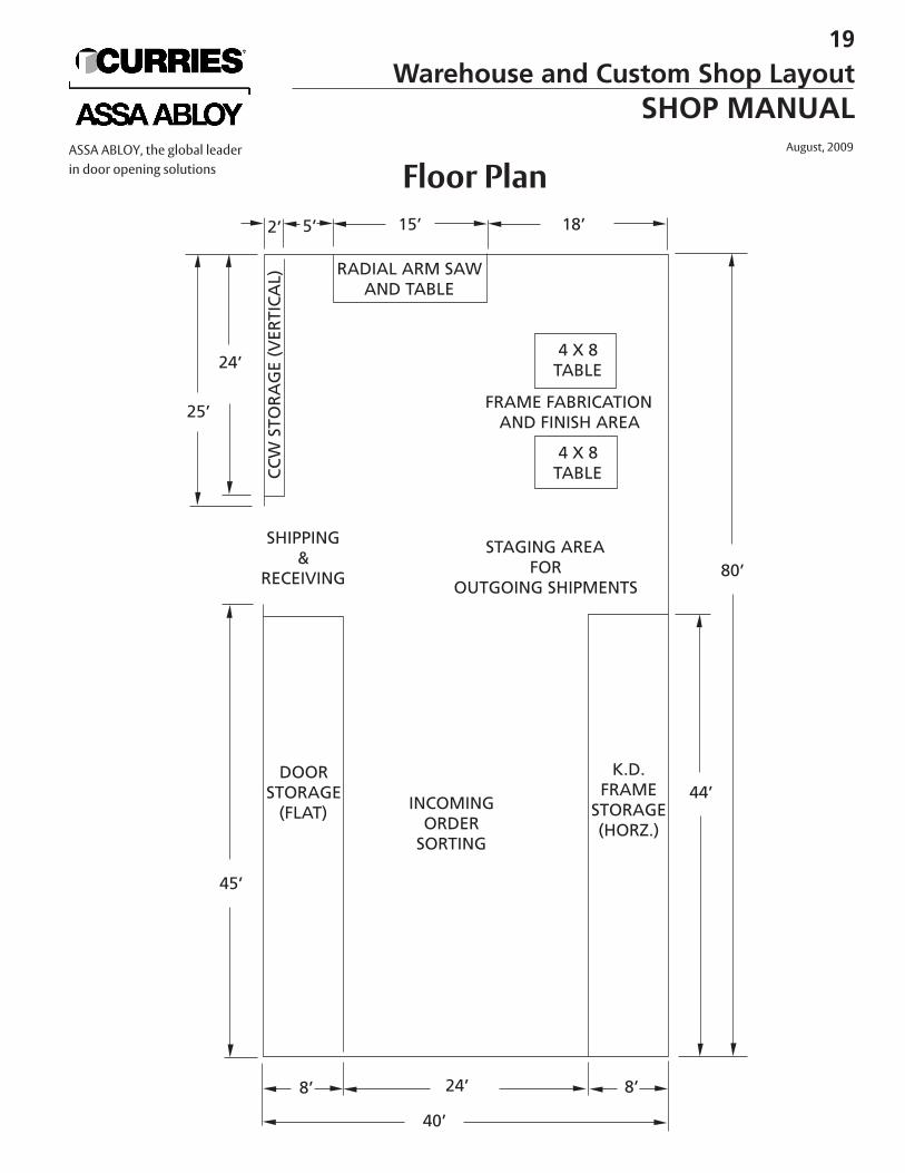
19
Warehouse and Custom Shop LayoutSHOP MANUAL
August, 2009ASSA ABLOY, the global leaderin door opening solutions Floor Plan
RECOMMENDED SHOP EQUIPMENTThe following is a list of equipment recommended by Curries Company for use in the shop. This list representsequipment with features and attachments needed for the wide range of operations performed in a hollow metalshop. Other manufacturers’ brands may be used providing the specifications are equivalent to those listedbelow.
POWER TOOLSRADIAL ARM SAW
SABRE SAW
GRINDER
ALTERNATE“The Original (Dewalt) Model 3579 16" Metal CuttingRadial Arm Saw, 230/460 volt, 3 phase, 7.5 h.p. motor,3425 r.p.m., 52" arm.
“Ellis” Mitre Band Saw Model 2000, 220 volt single phase.
“Dewalt” Model GER 16" Radial Arm Saw220/400 volt, 3 phase, 5 h.p. motor, 3425 r.p.m.Blade — “The Blade Manufacturing Company” — MetalCutting Blade, Semi-hi speed 16" x 1/8" x 1" x 250 teeth
ALTERNATE“Porter Cable” Model 548 Jigsaw - variable speed, 3.5 amps, 4,500strokes per minute.
“Milwaukee” Model 6256 Jigsaw, Variable Speed, 3.8amps, 3100 strokes per minute.Blades “Milwaukee” Parts Number
48-43-0140 2-3/4" 21 tooth high speed steel48-42-2166 3" 24 tooth Bi-Metal
ALTERNATE“Sioux” Model V5232 9" Vertical Heavy Duty Air Grinder,6000 r.p.m., 3 h.p.Disc Holder — “Norton” Model 43245 7"Retaining Nut — “Norton” Model 66NS
“Milwaukee” Model 6066 7" Electric Heavy Duty Grinder,3.5 h.p motor, 15 amp, 120 volt, 6000 r.p.m.Rubber pad assembly — Model 49-36-3800 7"Retaining Nut — Model 49-40-0360Discs“Milwaukee” 7" dia.
Grit Parts Number24 48-80-205060 48-80-220080 48-80-2250
20
Recommended Shop EquipmentSHOP MANUALAugust, 2009 ASSA ABLOY, the global leader
in door opening solutions
POWER TOOLS (continued)Die Grinder
Vibrating Sander
WELDERSArc Welder
Wire Welder
DRILLS
ELECTRIC SCREWDRIVER
KETT SAW
“Milwaukee” Model 5192 Electric Die Grinder, 4.5 amps,21,000 r.p.m., 1/4" collet
ALTERNATE“Chicago Pneumatic” Model CP-860 Air Powered DieGrinder, 24,000 r.p.m., 1/4" collet
“National—Detroit" Model DAQ Dual Action Air SanderDiscs“Norton” 5" dia. pads Grit Parts Number
60D 30280240D 31032
ALTERNATE“Milwaukee” Model 6012 Heavy Duty Electric Orbital Sander, 12,000 orbits/min., 5 amps
“Lincoln” Model AC-225-S Arc Welding SystemAmps: AC range 40-225Voltage: AC 79v20% duty cycle
ALTERNATE“Lincoln” AC/DC 225/125 Arc Welding System
“Airco” Model 130 Mini Arc Portable Welder, 130 amps,DC output, 60v output voltage, 20% duty cycle“Airco” Model Dip-Pak 200 Welding System
200 amp: 60% duty cycleVoltage: AC 115v
DC 20-40VWire Size: .035-.045
“Miller” Model 250 Millermatic Wire Welder 200 amp: 60% duty cycleWireSize: .023-.045
“Milwaukee” Model 0222-1, 3/8" Electric Drill, Reversible“Sioux” Model 1445 1/4" Air Drill, Non-reversible
“Milwaukee” Model 6798-1, 1/4", 2500 r.p.m., Reversible
“Kett” Plunge Saw Model KS-23 AM-5.5 amp, 1500 r.p.m.
21
Recommended Shop EquipmentSHOP MANUAL
August, 2009ASSA ABLOY, the global leaderin door opening solutions
POWER TOOLS (continued)Sand Blaster
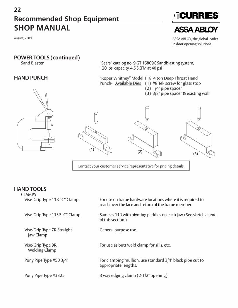
HAND PUNCH
HAND TOOLSCLAMPS
Vise-Grip Type 11R “C” Clamp
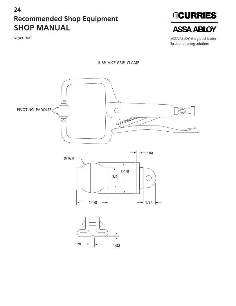
Vise-Grip Type 11SP “C” Clamp
Vise-Grip Type 7R StraightJaw Clamp
Vise-Grip Type 9R Welding Clamp
Pony Pipe Type #50 3/4"
Pony Pipe Type #3325
“Sears” catalog no. 9 GT 16809C Sandblasting system,120 lbs. capacity, 4.5 SCFM at 40 psi
“Roper Whitney” Model 118, 4 ton Deep Throat HandPunch- Available Dies (1) #8 Tek screw for glass stop
(2) 1/4" pipe spacer(3) 3/8" pipe spacer & existing wall
For use on frame hardware locations where it is required to reach over the face and return of the frame member.
Same as 11R with pivoting paddles on each jaw. (See sketch at endof this section.)
General purpose use.
For use as butt weld clamp for sills, etc.
For clamping mullion, use standard 3/4" black pipe cut to appropriate lengths.
3 way edging clamp (2-1/2" opening).
22
Recommended Shop EquipmentSHOP MANUALAugust, 2009 ASSA ABLOY, the global leader
in door opening solutions
Contact your customer service representative for pricing details.
ASSORTED HAND TOOLSHAMMERS
FRAMING SQUARES
COMBINATION SQUARES
ASSORTED SCREWDRIVERS
STEEL TAPES
FLEXIBLE PUTTY KNIVES
FILES
POP RIVET GUN
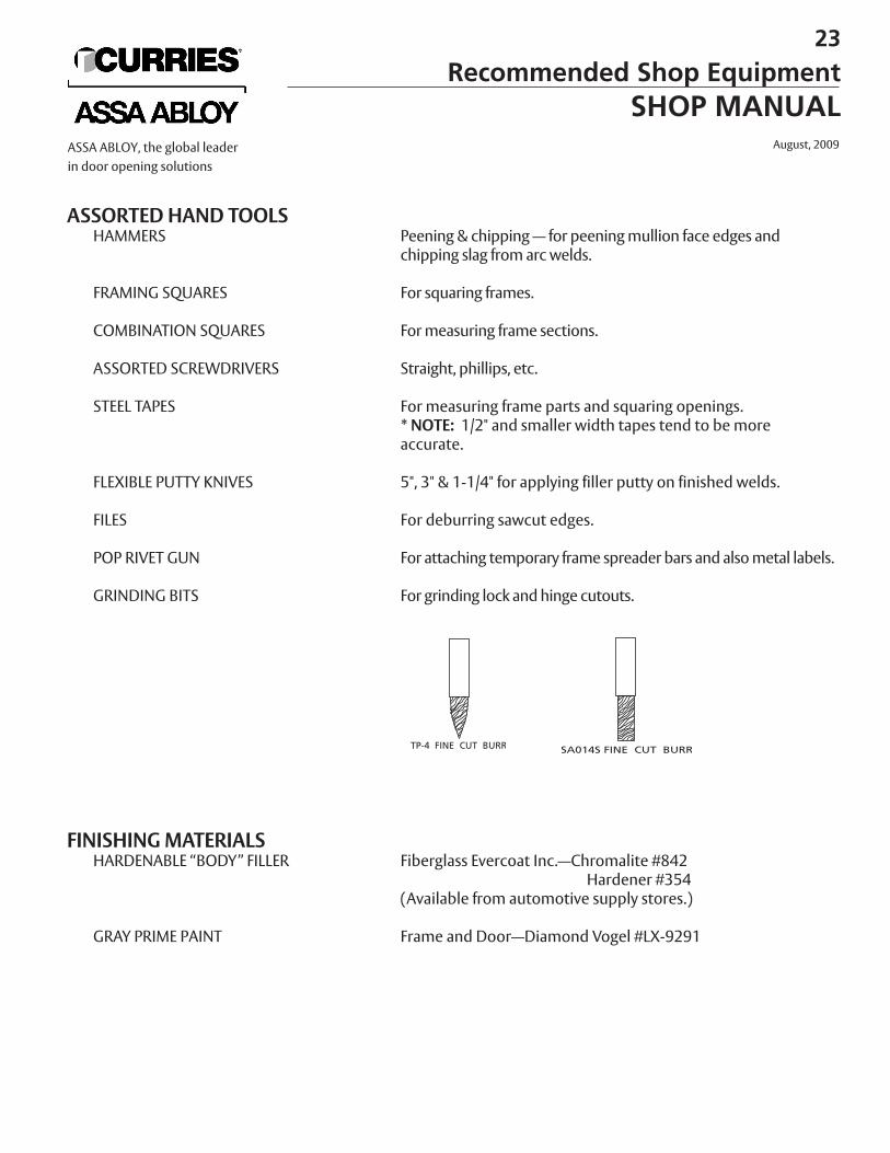
GRINDING BITS
FINISHING MATERIALSHARDENABLE “BODY” FILLER
GRAY PRIME PAINT
Peening & chipping — for peening mullion face edges andchipping slag from arc welds.
For squaring frames.
For measuring frame sections.
Straight, phillips, etc.
For measuring frame parts and squaring openings.* NOTE: 1/2" and smaller width tapes tend to be more accurate.
5", 3" & 1-1/4" for applying filler putty on finished welds.
For deburring sawcut edges.
For attaching temporary frame spreader bars and also metal labels.
For grinding lock and hinge cutouts.
Fiberglass Evercoat Inc.—Chromalite #842Hardener #354
(Available from automotive supply stores.)
Frame and Door—Diamond Vogel #LX-9291
23
Recommended Shop EquipmentSHOP MANUAL
August, 2009ASSA ABLOY, the global leaderin door opening solutions
1/8 1/32
1-1/8
9/16 R
PIVOTING PADDLES
II SP VICE-GRIP CLAMP
3/41-1/8
7/16
.104
24
Recommended Shop EquipmentSHOP MANUALAugust, 2009 ASSA ABLOY, the global leader
in door opening solutions
U.L. SECOND LOCATION MANUFACTURING PROGRAM
Underwriters Laboratories has a program by which a Curries door and frame distributor can modify doors and build frames to meet U.L. labeling criteria andapply a U.L. label in his shop. The program is called “U.L. Second LocationProcedure”.
Under this program you can stock doors that bear a special fire door part for further processing label instead of stocking some A label, B label and C label doors.Doors which bear this special label may be used as received or they may be modified by installing a window kit, a louver, drilling and tapping for hardwaremounting and other modifications as described in the U.L. procedure manual.These doors can then have a U.L. label applied at your shop to meet your customers’ requirements.
Standard non-label frames and frame parts may be stocked as opposed to labeledframes. Standard frames may simply have a label applied or frame components and sticks may be fabricated into a finished frame and labeled.
Warnock Hersey International offers similar second location procedures.
For further information on this program please contact your Field Sales Manager or the factory.
25
Manufacturing ProgramSHOP MANUAL
August, 2009ASSA ABLOY, the global leaderin door opening solutions
FRAME WELDING PREPARATION
It is highly recommended that all frame pieces be prepared and checked thoroughlybefore attempting to assemble and weld them together. This precaution, in many cases,can save time and scrap loss. Once the frame structure is welded, problems are nearlyimpossible to correct. The following preparation pointers will help eliminate frame welding problems.
• Always check all frame parts with drawings and measure all dimensions includinghardware locations and size.
• Accurately measure all profile dimensions on the mating parts such as jamb depth, rabbet, stop dimensions and face dimensions to be certain of a matching fit of the jamb and head profile, jamb/head and transom or mullion profile or sill andjamb/mullion profile.
• Make certain all saw miter cuts are square across the profile. Only a slight angularity can cause big problems in flatness, squareness and overall dimensional control of the finished frame.
• De-burr all saw cut edges using a file but take special care to avoid filing at more than aslight angle to the plane of the metal so as not to cut away material at the surfaces to be joined. If these edges are too thin, this can lead to burning through when welding.
• When face welding mullion it is helpful to peen the mating edge slightly inward using a peening hammer. This provides a slight recess between the mullion face and the jamb face for welding so that the weld will not be all ground off in the finishing process. Take care not to deform the face too far back from the edge so that the finished appearance will be flat and smooth after grinding the weld.
• It is very helpful when assembling, clamping and welding to place spacer bars in the opening between rabbets. These bars, cut to the exact opening size, will help considerably in maintaining dimensional control.
• It is very important when welding frames for a door opening to start with the hinge jamb and the head first. Clamp and square the hinge miter and make certain the distance from the head rabbet to the top hinge cut-out is correct and accurate before welding. This is necessary to assure the door will fit the opening properly and thecorrect clearance will be maintained.
• Check and recheck squareness and flatness of the frame after clamping and after each welding operation. This will make any required straightening much easier. One good method of monitoring overall squareness, effective especially on multiple opening frames, is to measure diagonally across each opening plus across the overall frame. For example, a frame with door opening, transom and multiple sidelites should be measured or “cross taped” over the door opening, the transom opening and over both openings as well as the side lite opening and finally the overall frame. Straightening methods can very. One way is to clamp the longer diagonal and force it a distance of one half the difference between the two diagonals of a given opening.
1 Welding Procedures
SHOP MANUALAugust, 2009ASSA ABLOY, the global leader
in door opening solutions
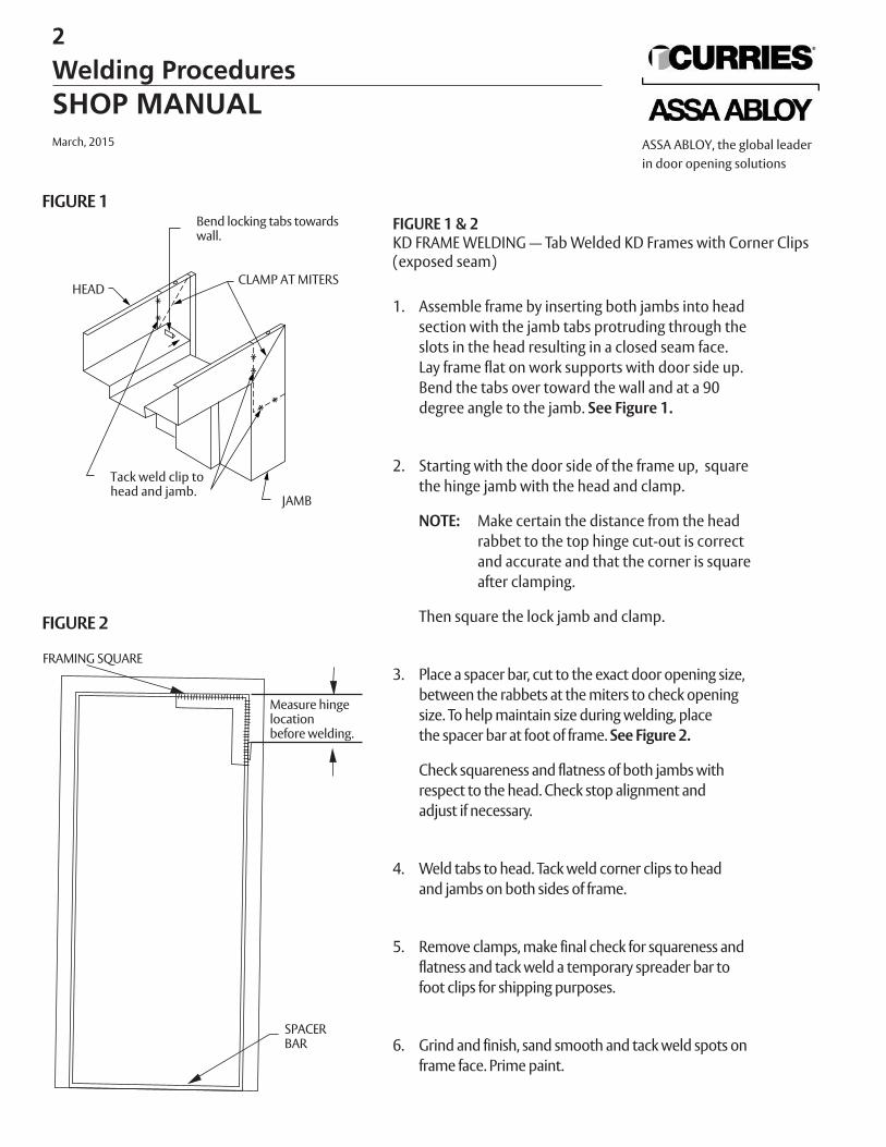
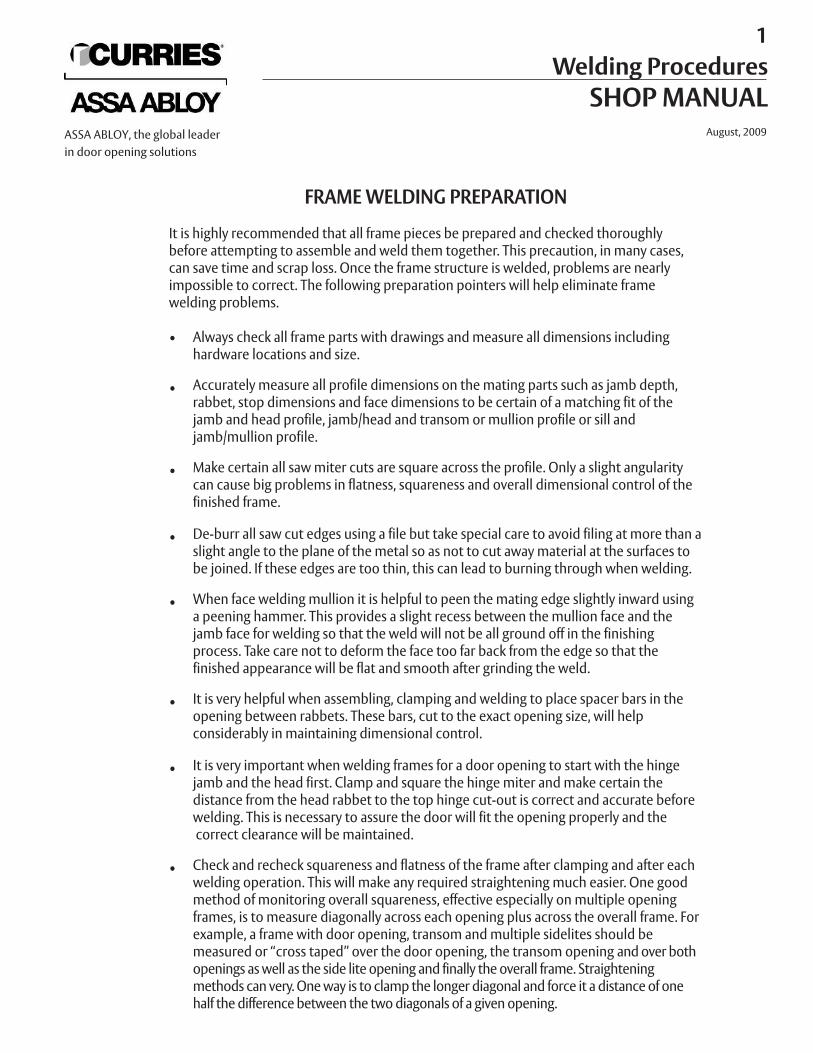
FIGURE 1 & 2KD FRAME WELDING — Tab Welded KD Frames with Corner Clips(exposed seam)
1. Assemble frame by inserting both jambs into headsection with the jamb tabs protruding through theslots in the head resulting in a closed seam face.Lay frame flat on work supports with door side up. Bend the tabs over toward the wall and at a 90degree angle to the jamb. See Figure 1.
2. Starting with the door side of the frame up, square the hinge jamb with the head and clamp.
NOTE: Make certain the distance from the headrabbet to the top hinge cut-out is correctand accurate and that the corner is squareafter clamping.
Then square the lock jamb and clamp.
3. Place a spacer bar, cut to the exact door opening size,between the rabbets at the miters to check opening size. To help maintain size during welding, placethe spacer bar at foot of frame. See Figure 2.
Check squareness and flatness of both jambs withrespect to the head. Check stop alignment andadjust if necessary.
4. Weld tabs to head. Tack weld corner clips to headand jambs on both sides of frame.
5. Remove clamps, make final check for squareness andflatness and tack weld a temporary spreader bar tofoot clips for shipping purposes.
6. Grind and finish, sand smooth and tack weld spots on frame face. Prime paint.
Bend locking tabs towardswall.
HEAD
Tack weld clip tohead and jamb.
JAMB
CLAMP AT MITERS
FIGURE 1
FIGURE 2
Measure hingelocationbefore welding.
SPACERBAR
FRAMING SQUARE
2
Welding ProceduresSHOP MANUALMarch, 2015 ASSA ABLOY, the global leader
in door opening solutions
FIGURE 1 — 3
MITER WELDED KD FRAMES1. Follow steps 1, 2 & 3 of KD Tab Welded Frame
Procedure.
2. When frame is properly flat and square, tack weld both ends of the miters on the face side. Removethe miter clamps. See Figure 1.
NOTE: If jambs are furnished without corner clips,or breakaway corner clips have been removed, miters can be welded on the insideof the face thereby minimizing weld grindingbefore finishing according to Step 6.
3. If frame is out of square see Step 4.If frame is still square and flat, weld a bead along themiter seam between tacks. Do not weld over tacks.
4. To correct minor out of squareness:A. To Move Jamb Outward (see Figure 2)
Start bead next to but not on inside tack and weldtoward and over outside tack.
B. To Move Jamb Inward (see Figure 3)Reverse the process.
Normal cooling of the weld should move the jambs in the direction desired. If more than a slight movement is desired, squirt water from a plastic squirt bottle on the weld immediately after welding tospeed up the cooling rate. This will cause more shrinkage and movement.
5. Flip frame over and repeat process.
6. Finally weld the locking tabs to the head as shown inFigure 1.
7. Grind all welds smooth, fill voids with body filler, grind and sand smooth and prime paint exposed areas. Tack weld temporary spreader bar to foot clips.
Bend locking tabs towardwall.
HEAD
JAMB
FIGURE 1
FIGURE 2— To Move Jamb Outward
FIGURE 3 — To Move Jamb Inward
3 Welding Procedures
SHOP MANUALMarch, 2015ASSA ABLOY, the global leader
in door opening solutions
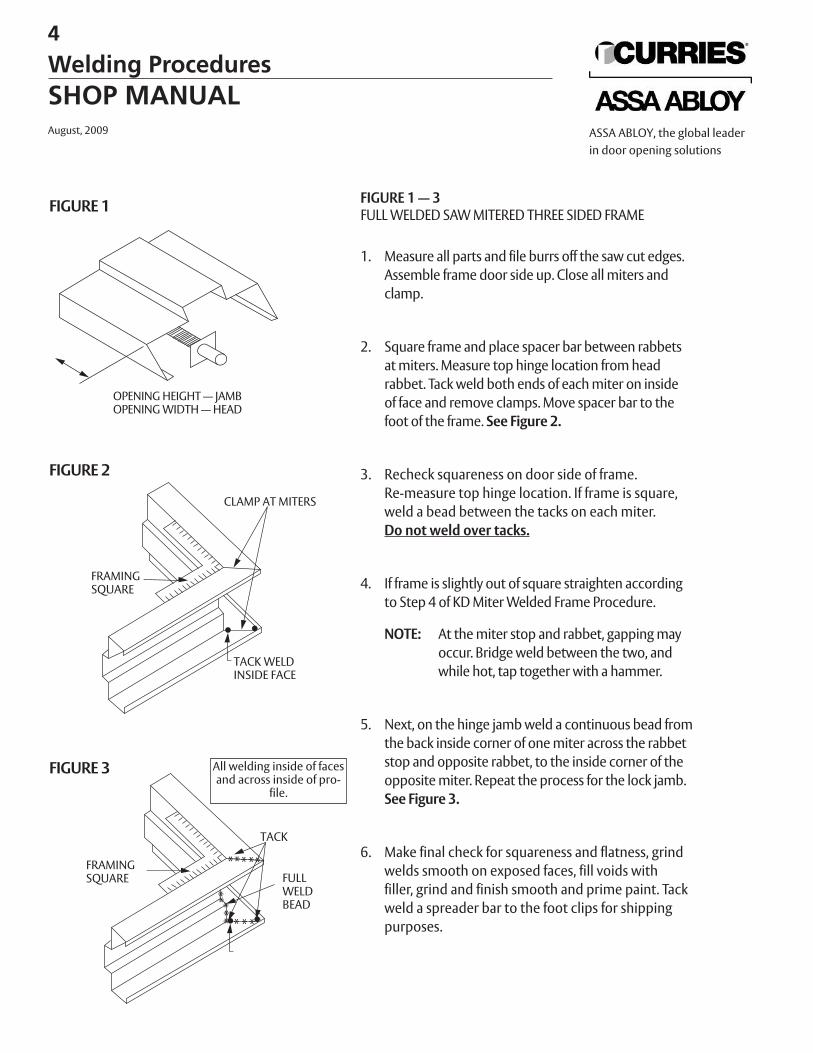
FIGURE 1 — 3FULL WELDED SAW MITERED THREE SIDED FRAME
1. Measure all parts and file burrs off the saw cut edges.Assemble frame door side up. Close all miters and clamp.
2. Square frame and place spacer bar between rabbetsat miters. Measure top hinge location from head rabbet. Tack weld both ends of each miter on insideof face and remove clamps. Move spacer bar to thefoot of the frame. See Figure 2.
3. Recheck squareness on door side of frame. Re-measure top hinge location. If frame is square, weld a bead between the tacks on each miter.Do not weld over tacks.
4. If frame is slightly out of square straighten accordingto Step 4 of KD Miter Welded Frame Procedure.
NOTE: At the miter stop and rabbet, gapping mayoccur. Bridge weld between the two, andwhile hot, tap together with a hammer.
5. Next, on the hinge jamb weld a continuous bead fromthe back inside corner of one miter across the rabbetstop and opposite rabbet, to the inside corner of theopposite miter. Repeat the process for the lock jamb.See Figure 3.
6. Make final check for squareness and flatness, grindwelds smooth on exposed faces, fill voids with filler, grind and finish smooth and prime paint. Tackweld a spreader bar to the foot clips for shippingpurposes.
FIGURE 1
OPENING HEIGHT — JAMBOPENING WIDTH — HEAD
CLAMP AT MITERS
FIGURE 2
TACK WELDINSIDE FACE
FRAMINGSQUARE
FIGURE 3
FRAMINGSQUARE FULL
WELDBEAD
TACK
All welding inside of facesand across inside of pro-
file.
4
Welding ProceduresSHOP MANUALAugust, 2009 ASSA ABLOY, the global leader
in door opening solutions
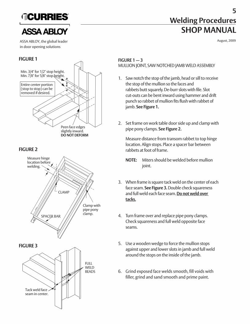
FIGURE 1 — 3MULLION JOINT, SAW NOTCHED JAMB WELD ASSEMBLY
1. Saw notch the stop of the jamb, head or sill to receivethe stop of the mullion so the faces and rabbets butt squarely. De-burr slots with file. Slotcut-outs can be bent inward using hammer and driftpunch so rabbet of mullion fits flush with rabbet of jamb. See Figure 1.
2. Set frame on work table door side up and clamp withpipe pony clamps. See Figure 2.
Measure distance from transom rabbet to top hingelocation. Align stops. Place a spacer bar between rabbets at foot of frame.
NOTE: Miters should be welded before mullion joint.
3. When frame is square tack weld on the center of eachface seam. See Figure 3. Double check squareness and full weld each face seam. Do not weld over tacks.
4. Turn frame over and replace pipe pony clamps. Check squareness and full weld opposite face seams.
5. Use a wooden wedge to force the mullion stops against upper and lower slots in jamb and full weldaround the stops on the inside of the jamb.
6. Grind exposed face welds smooth, fill voids withfiller, grind and sand smooth and prime paint.
FIGURE 1
Min. 3/4" for 1/2" stop height.Min. 7/8" for 5/8" stop height.
Entire center portion(stop to stop) can beremoved if desired.
Peen face edges slightly inward.DO NOT DEFORM
FIGURE 2
FIGURE 3
Measure hingelocation beforewelding.
Clamp withpipe pony clamp.
CLAMP
SPACER BAR
FULL WELDBEADS
Tack weld faceseam in center.
5 Welding Procedures
SHOP MANUALAugust, 2009ASSA ABLOY, the global leader
in door opening solutions
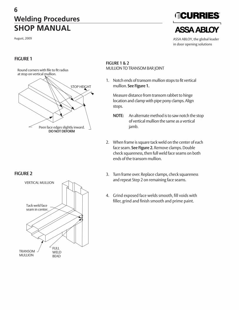
FIGURE 1 & 2MULLION TO TRANSOM BAR JOINT
1. Notch ends of transom mullion stops to fit verticalmullion. See Figure 1.
Measure distance from transom rabbet to hinge location and clamp with pipe pony clamps. Alignstops.
NOTE: An alternate method is to saw notch the stopof vertical mullion the same as a verticaljamb.
2. When frame is square tack weld on the center of eachface seam. See Figure 2. Remove clamps. Doublecheck squareness, then full weld face seams on bothends of the transom mullion.
3. Turn frame over. Replace clamps, check squarenessand repeat Step 2 on remaining face seams.
4. Grind exposed face welds smooth, fill voids withfiller, grind and finish smooth and prime paint.
FIGURE 1
STOP HEIGHT
Round corners with file to fit radiusat stop on vertical mullion.
Peen face edges slightly inward.DO NOT DEFORM
FIGURE 2
VERTICAL MULLION
Tack weld face seam in center.
FULLWELDBEAD
TRANSOMMULLION
6
Welding ProceduresSHOP MANUALAugust, 2009 ASSA ABLOY, the global leader
in door opening solutions
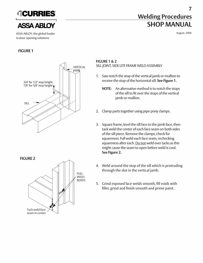
FIGURE 1 & 2SILL JOINT, SIDE LITE FRAME WELD ASSEMBLY
1. Saw notch the stop of the vertical jamb or mullion toreceive the stop of the horizontal sill. See Figure 1.
NOTE: An alternative method is to notch the stopsof the sill to fit over the stops of the verticaljamb or mullion.
2. Clamp parts together using pipe pony clamps.
3. Square frame, level the sill face to the jamb face, thentack weld the center of each face seam on both sidesof the sill piece. Remove the clamps, check forsquareness. Full weld each face seam, recheckingsquareness after each. Do notweld over tacks as thismight cause the seam to open before weld is cool.See Figure 2.
4. Weld around the stop of the sill which is protrudingthrough the slot in the vertical jamb.
5. Grind exposed face welds smooth, fill voids withfiller, grind and finish smooth and prime paint.
FIGURE 1
SILL
VERTICALJAMB
3/4" for 1/2" stop height.7/8" for 5/8" stop height.
FIGURE 2
FULLWELDBEADS
Tack weld faceseam in center
7 Welding Procedures
SHOP MANUALAugust, 2009ASSA ABLOY, the global leader
in door opening solutions
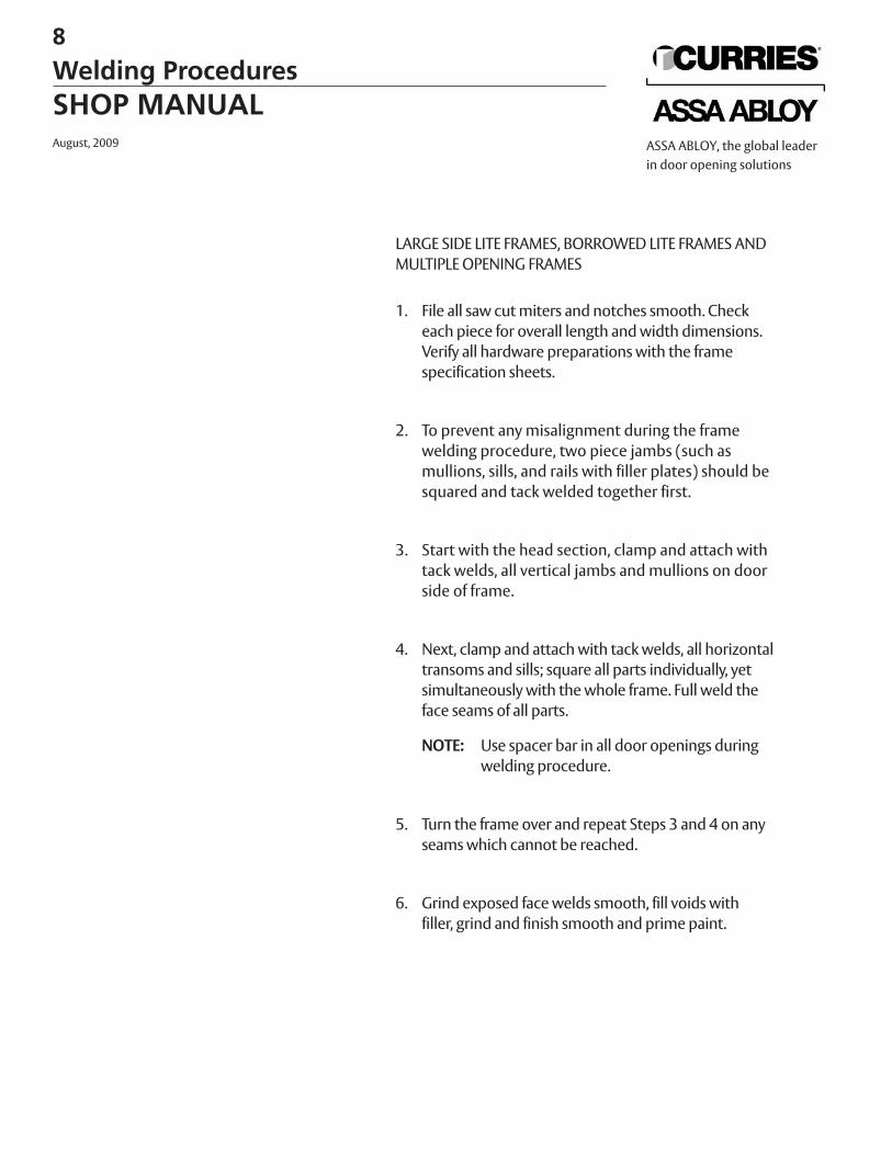
LARGE SIDE LITE FRAMES, BORROWED LITE FRAMES ANDMULTIPLE OPENING FRAMES
1. File all saw cut miters and notches smooth. Checkeach piece for overall length and width dimensions.Verify all hardware preparations with the framespecification sheets.
2. To prevent any misalignment during the frame welding procedure, two piece jambs (such as mullions, sills, and rails with filler plates) should be squared and tack welded together first.
3. Start with the head section, clamp and attach with tack welds, all vertical jambs and mullions on doorside of frame.
4. Next, clamp and attach with tack welds, all horizontaltransoms and sills; square all parts individually, yetsimultaneously with the whole frame. Full weld theface seams of all parts.
NOTE: Use spacer bar in all door openings duringwelding procedure.
5. Turn the frame over and repeat Steps 3 and 4 on anyseams which cannot be reached.
6. Grind exposed face welds smooth, fill voids withfiller, grind and finish smooth and prime paint.
8
Welding ProceduresSHOP MANUALAugust, 2009 ASSA ABLOY, the global leader
in door opening solutions
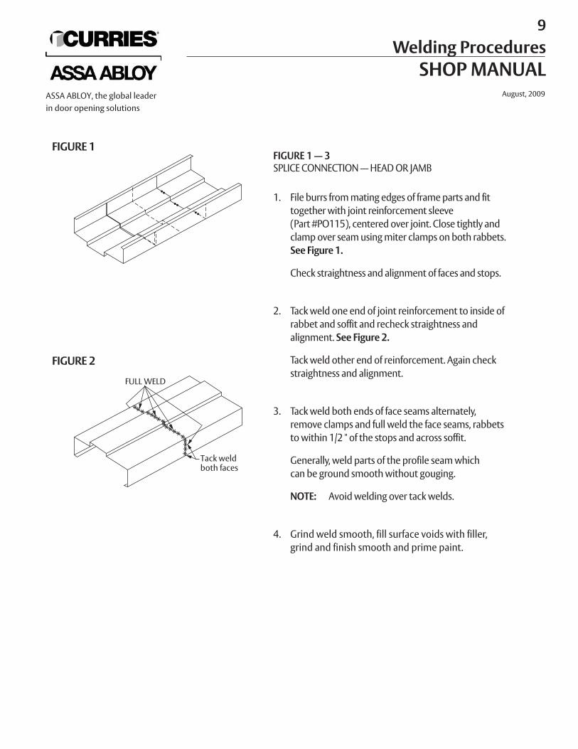
FIGURE 1 — 3SPLICE CONNECTION — HEAD OR JAMB
1. File burrs from mating edges of frame parts and fittogether with joint reinforcement sleeve (Part #PO115), centered over joint. Close tightly and clamp over seam using miter clamps on both rabbets.See Figure 1.
Check straightness and alignment of faces and stops.
2. Tack weld one end of joint reinforcement to inside ofrabbet and soffit and recheck straightness and alignment. See Figure 2.
Tack weld other end of reinforcement. Again checkstraightness and alignment.
3. Tack weld both ends of face seams alternately, remove clamps and full weld the face seams, rabbetsto within 1/2 " of the stops and across soffit.
Generally, weld parts of the profile seam whichcan be ground smooth without gouging.
NOTE: Avoid welding over tack welds.
4. Grind weld smooth, fill surface voids with filler, grind and finish smooth and prime paint.
FIGURE 1
FIGURE 2
FULL WELD
Tack weldboth faces
9 Welding Procedures
SHOP MANUALAugust, 2009ASSA ABLOY, the global leader
in door opening solutions
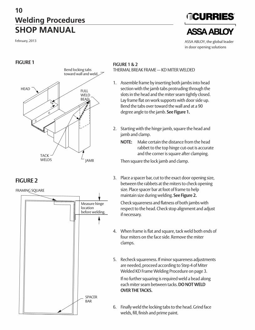
FIGURE 1 & 2THERMAL BREAK FRAME — KD MITER WELDED
1. Assemble frame by inserting both jambs into headsection with the jamb tabs protruding through the slots in the head and the miter seam tightly closed.Lay frame flat on work supports with door side up.Bend the tabs over toward the wall and at a 90 degree angle to the jamb. See Figure 1.
2. Starting with the hinge jamb, square the head and jamb and clamp.
NOTE: Make certain the distance from the headrabbet to the top hinge cut-out is accurate and the corner is square after clamping.
Then square the lock jamb and clamp.
3. Place a spacer bar, cut to the exact door opening size,between the rabbets at the miters to check opening size. Place spacer bar at foot of frame to help maintain size during welding. See Figure 2.
Check squareness and flatness of both jambs withrespect to the head. Check stop alignment and adjustif necessary.
4. When frame is flat and square, tack weld both ends offour miters on the face side. Remove the miter clamps.
5. Recheck squareness. If minor squareness adjustmentsare needed, proceed according to Step 4 of MiterWelded KD Frame Welding Procedure on page 3.
If no further squaring is required weld a bead alongeach miter seam between tacks. DO NOT WELDOVER THE TACKS.
6. Finally weld the locking tabs to the head. Grind facewelds, fill, finish and prime paint.
Bend locking tabs toward wall and weld.
HEAD
JAMB
FIGURE 1
FULLWELDBEAD
TACKWELDS
FIGURE 2
Measure hingelocationbefore welding.
SPACERBAR
FRAMING SQUARE
10
Welding ProceduresSHOP MANUALFebruary, 2013 ASSA ABLOY, the global leader
in door opening solutions
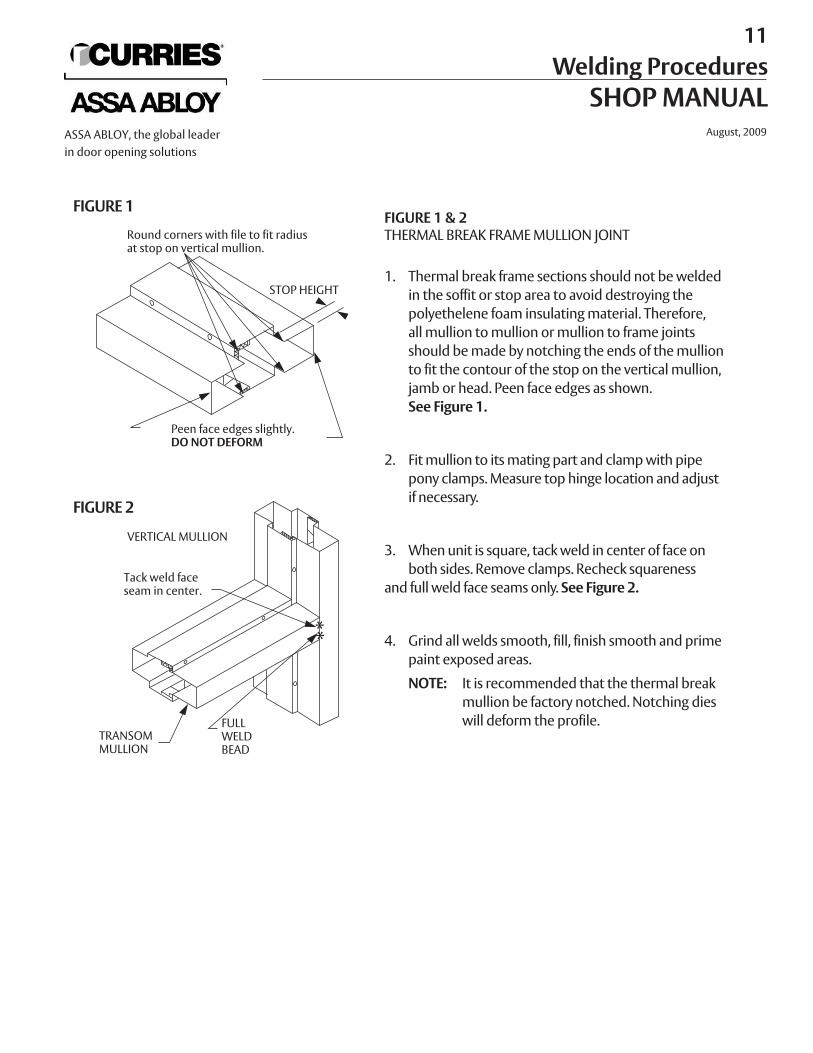
FIGURE 1 & 2THERMAL BREAK FRAME MULLION JOINT
1. Thermal break frame sections should not be welded in the soffit or stop area to avoid destroying thepolyethelene foam insulating material. Therefore,all mullion to mullion or mullion to frame joints should be made by notching the ends of the mullionto fit the contour of the stop on the vertical mullion,jamb or head. Peen face edges as shown. See Figure 1.
2. Fit mullion to its mating part and clamp with pipe pony clamps. Measure top hinge location and adjustif necessary.
3. When unit is square, tack weld in center of face onboth sides. Remove clamps. Recheck squareness
and full weld face seams only. See Figure 2.
4. Grind all welds smooth, fill, finish smooth and primepaint exposed areas.
NOTE: It is recommended that the thermal breakmullion be factory notched. Notching dies will deform the profile.
FIGURE 1
Round corners with file to fit radiusat stop on vertical mullion.
Peen face edges slightly.DO NOT DEFORM
STOP HEIGHT
FIGURE 2
VERTICAL MULLION
Tack weld faceseam in center.
TRANSOM MULLION
FULLWELDBEAD
11Welding Procedures
SHOP MANUALAugust, 2009ASSA ABLOY, the global leader
in door opening solutions
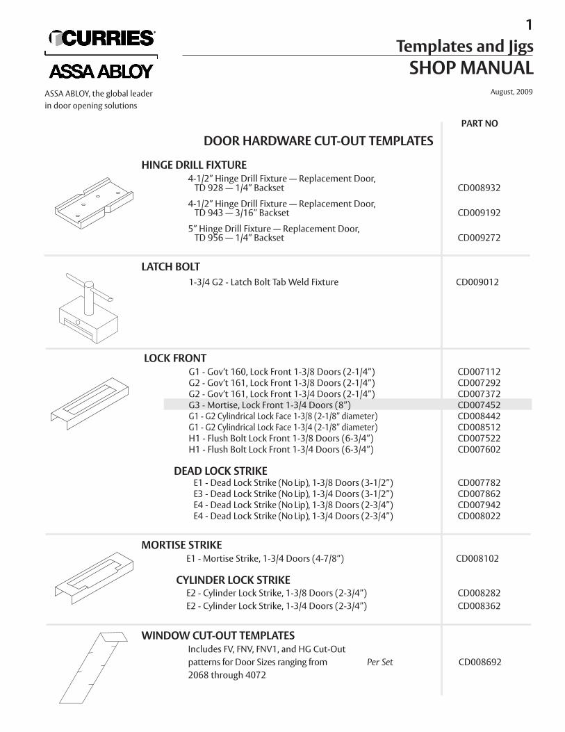
DOOR HARDWARE CUT-OUT TEMPLATES
HINGE DRILL FIXTURE4-1/2” Hinge Drill Fixture — Replacement Door, TD 928 — 1/4” Backset CD008932
4-1/2” Hinge Drill Fixture — Replacement Door, TD 943 — 3/16” Backset CD009192
5” Hinge Drill Fixture — Replacement Door, TD 956 — 1/4” Backset CD009272
LATCH BOLT1-3/4 G2 - Latch Bolt Tab Weld Fixture CD009012
LOCK FRONTG1 - Gov’t 160, Lock Front 1-3/8 Doors (2-1/4”) CD007112G2 - Gov’t 161, Lock Front 1-3/8 Doors (2-1/4”) CD007292G2 - Gov’t 161, Lock Front 1-3/4 Doors (2-1/4”) CD007372G3 - Mortise, Lock Front 1-3/4 Doors (8”) CD007452G1 - G2 Cylindrical Lock Face 1-3/8 (2-1/8” diameter) CD008442G1 - G2 Cylindrical Lock Face 1-3/4 (2-1/8” diameter) CD008512H1 - Flush Bolt Lock Front 1-3/8 Doors (6-3/4”) CD007522H1 - Flush Bolt Lock Front 1-3/4 Doors (6-3/4”) CD007602
DEAD LOCK STRIKEE1 - Dead Lock Strike (No Lip), 1-3/8 Doors (3-1/2”) CD007782E3 - Dead Lock Strike (No Lip), 1-3/4 Doors (3-1/2”) CD007862E4 - Dead Lock Strike (No Lip), 1-3/8 Doors (2-3/4”) CD007942E4 - Dead Lock Strike (No Lip), 1-3/4 Doors (2-3/4”) CD008022
MORTISE STRIKEE1 - Mortise Strike, 1-3/4 Doors (4-7/8”) CD008102
CYLINDER LOCK STRIKEE2 - Cylinder Lock Strike, 1-3/8 Doors (2-3/4”) CD008282E2 - Cylinder Lock Strike, 1-3/4 Doors (2-3/4”) CD008362
WINDOW CUT-OUT TEMPLATESIncludes FV, FNV, FNV1, and HG Cut-Out patterns for Door Sizes ranging from Per Set CD0086922068 through 4072
PART NO
1 Templates and JigsSHOP MANUAL
August, 2009ASSA ABLOY, the global leaderin door opening solutions
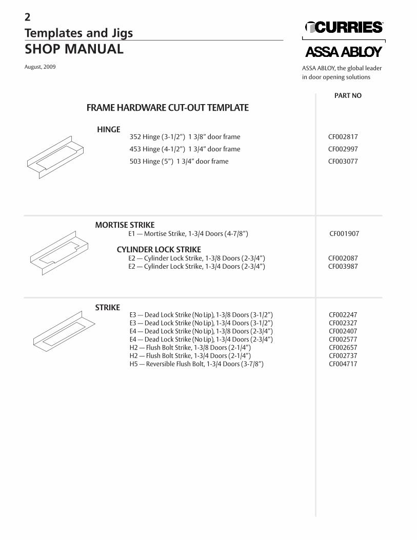
FRAME HARDWARE CUT-OUT TEMPLATE
HINGE352 Hinge (3-1/2”) 1 3/8” door frame CF002817
453 Hinge (4-1/2”) 1 3/4” door frame CF002997
503 Hinge (5”) 1 3/4” door frame CF003077
MORTISE STRIKEE1 — Mortise Strike, 1-3/4 Doors (4-7/8”) CF001907
CYLINDER LOCK STRIKEE2 — Cylinder Lock Strike, 1-3/8 Doors (2-3/4”) CF002087E2 — Cylinder Lock Strike, 1-3/4 Doors (2-3/4”) CF003987
STRIKEE3 — Dead Lock Strike (No Lip), 1-3/8 Doors (3-1/2”) CF002247 E3 — Dead Lock Strike (No Lip), 1-3/4 Doors (3-1/2”) CF002327 E4 — Dead Lock Strike (No Lip), 1-3/8 Doors (2-3/4”) CF002407 E4 — Dead Lock Strike (No Lip), 1-3/4 Doors (2-3/4”) CF002577 H2 — Flush Bolt Strike, 1-3/8 Doors (2-1/4”) CF002657H2 — Flush Bolt Strike, 1-3/4 Doors (2-1/4”) CF002737H5 — Reversible Flush Bolt, 1-3/4 Doors (3-7/8”) CF004717
PART NO
2
Templates and JigsSHOP MANUALAugust, 2009 ASSA ABLOY, the global leader
in door opening solutions
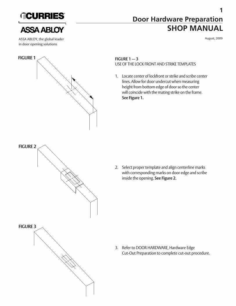
FIGURE 1 — 3USE OF THE LOCK FRONT AND STRIKE TEMPLATES
1. Locate center of lockfront or strike and scribe centerlines. Allow for door undercut when measuringheight from bottom edge of door so the center will coincide with the mating strike on the frame.See Figure 1.
2. Select proper template and align centerline marks with corresponding marks on door edge and scribeinside the opening. See Figure 2.
3. Refer to DOOR HARDWARE, Hardware Edge Cut-Out Preparation to complete cut-out procedure.
FIGURE 1
FIGURE 2
FIGURE 3
1
Door Hardware PreparationSHOP MANUAL
August, 2009ASSA ABLOY, the global leaderin door opening solutions
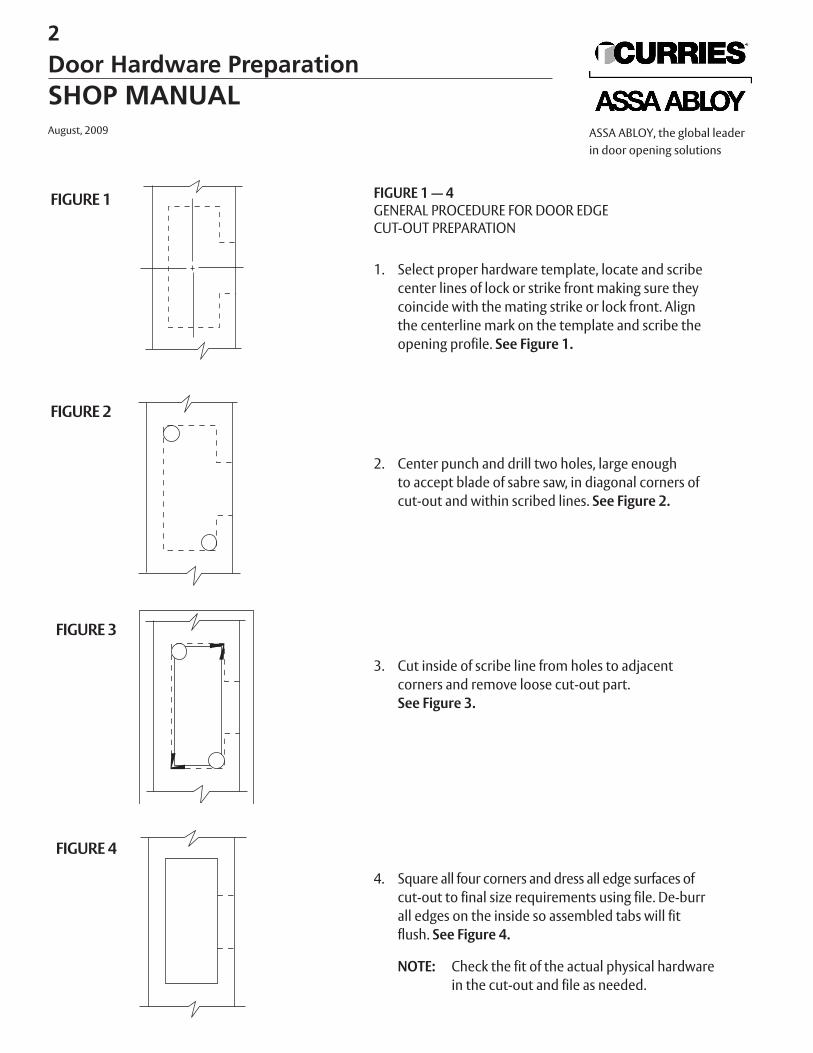
FIGURE 1 — 4GENERAL PROCEDURE FOR DOOR EDGE CUT-OUT PREPARATION
1. Select proper hardware template, locate and scribecenter lines of lock or strike front making sure theycoincide with the mating strike or lock front. Alignthe centerline mark on the template and scribe theopening profile. See Figure 1.
2. Center punch and drill two holes, large enoughto accept blade of sabre saw, in diagonal corners ofcut-out and within scribed lines. See Figure 2.
3. Cut inside of scribe line from holes to adjacentcorners and remove loose cut-out part. See Figure 3.
4. Square all four corners and dress all edge surfaces ofcut-out to final size requirements using file. De-burrall edges on the inside so assembled tabs will fit flush. See Figure 4.
NOTE: Check the fit of the actual physical hardware in the cut-out and file as needed.
FIGURE 1
FIGURE 2
FIGURE 3
FIGURE 4
2
Door Hardware PreparationSHOP MANUALAugust, 2009 ASSA ABLOY, the global leader
in door opening solutions
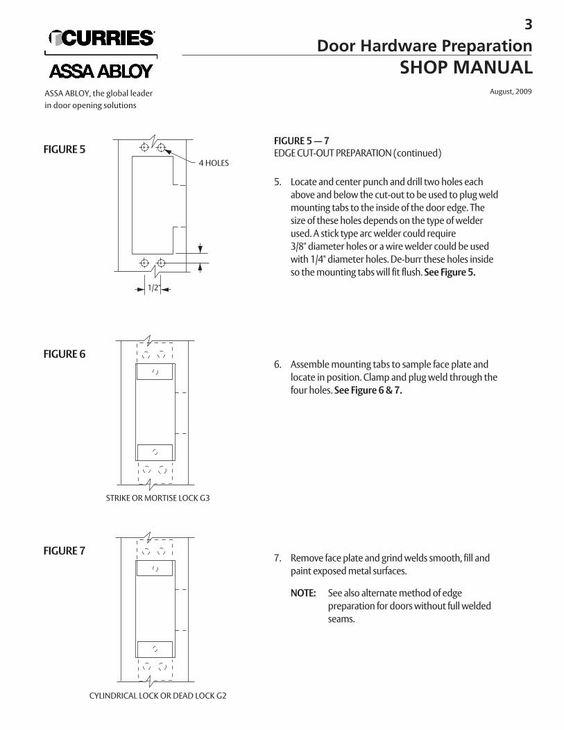
FIGURE 5 — 7EDGE CUT-OUT PREPARATION (continued)
5. Locate and center punch and drill two holes eachabove and below the cut-out to be used to plug weldmounting tabs to the inside of the door edge. The size of these holes depends on the type of welderused. A stick type arc welder could require 3/8" diameter holes or a wire welder could be usedwith 1/4" diameter holes. De-burr these holes insideso the mounting tabs will fit flush. See Figure 5.
6. Assemble mounting tabs to sample face plate andlocate in position. Clamp and plug weld through thefour holes. See Figure 6 & 7.
7. Remove face plate and grind welds smooth, fill andpaint exposed metal surfaces.
NOTE: See also alternate method of edge preparation for doors without full weldedseams.
FIGURE 5
FIGURE 6
4 HOLES
1/2"
STRIKE OR MORTISE LOCK G3
FIGURE 7
CYLINDRICAL LOCK OR DEAD LOCK G2
3
Door Hardware PreparationSHOP MANUAL
August, 2009ASSA ABLOY, the global leaderin door opening solutions
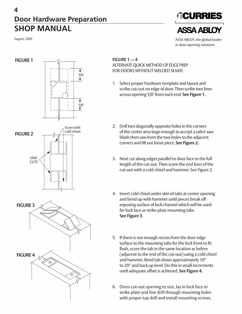
FIGURE 1 — 4ALTERNATE QUICK METHOD OF EDGE PREP FOR DOORS WITHOUT WELDED SEAMS
1. Select proper hardware template and layout andscribe cut-out on edge of door. Then scribe two linesacross opening 5/8" from each end. See Figure 1.
2. Drill two diagonally opposite holes in the cornersof the center area large enough to accept a sabre sawblade then saw from the two holes to the adjacentcorners and lift out loose piece. See Figure 2.
3. Next cut along edges parallel to door face to the fulllength of the cut-out. Then score the end lines of thecut-out with a cold chisel and hammer. See Figure 2.
4. Insert cold chisel under skin of tabs at center openingand bend up with hammer until pieces break offexposing surface of lock channel which will be usedfor lock face or strike plate mounting tabs.See Figure 3.
5. If there is not enough recess from the door edgesurface to the mounting tabs for the lock front to fitflush, score the tab in the same location as before(adjacent to the end of the cut-out) using a cold chiseland hammer. Bend tab down approximately 10°to 20° and back up level. Do this in small incrementsuntil adequate offset is achieved. See Figure 4.
6. Dress cut-out opening to size, lay in lock face orstrike plate and line drill through mounting holeswith proper tap drill and install mounting screws.
FIGURE 1
FIGURE 2
FIGURE 3
FIGURE 4
5/8"
5/8"
Score withcold chisel.
SAWCUTS
4
Door Hardware PreparationSHOP MANUALAugust, 2009 ASSA ABLOY, the global leader
in door opening solutions
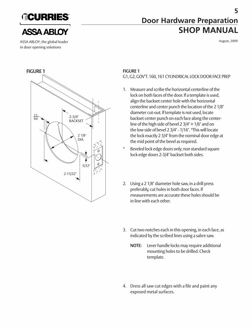
FIGURE 1G1, G2, GOV’T. 160, 161 CYLINDRICAL LOCK DOOR FACE PREP
1. Measure and scribe the horizontal centerline of thelock on both faces of the door. If a template is used,align the backset center hole with the horizontalcenterline and center punch the location of the 2 1/8"diameter cut-out. If template is not used, locate backset center punch on each face along the center-line of the high side of bevel 2 3/4" + 1/6" and onthe low side of bevel 2 3/4" - 1/16". *This will locatethe lock exactly 2 3/4" from the nominal door edge at the mid point of the bevel as required.
* Beveled lock edge doors only; non standard squarelock edge doors 2-3/4" backset both sides.
2. Using a 2 1/8" diameter hole saw, in a drill presspreferably, cut holes in both door faces. If measurements are accurate these holes should be in line with each other.
3. Cut two notches each in this opening, in each face, as indicated by the scribed lines using a sabre saw.
NOTE: Lever handle locks may require additionalmounting holes to be drilled. Check template.
4. Dress all saw cut edges with a file and paint any exposed metal surfaces.
FIGURE 1
2-3/4"BACKSET
1164
2 1/8"DIA.
2-15/32"
5/32"
5
Door Hardware PreparationSHOP MANUAL
August, 2009ASSA ABLOY, the global leaderin door opening solutions
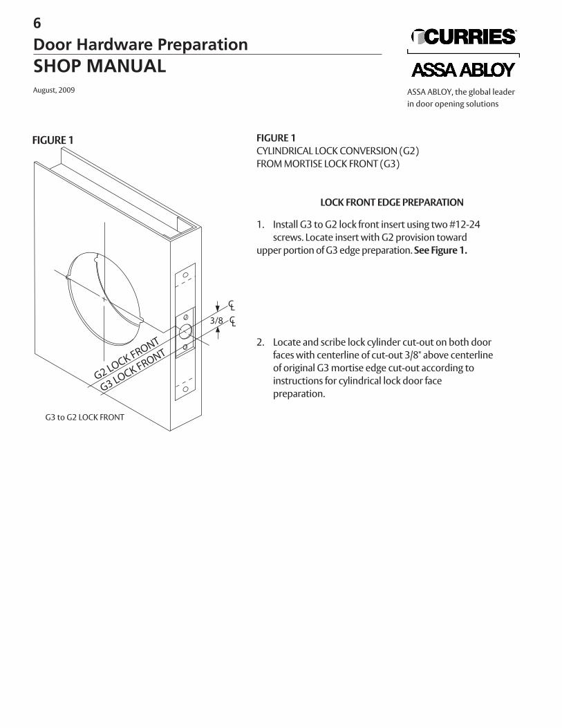
FIGURE 1CYLINDRICAL LOCK CONVERSION (G2) FROM MORTISE LOCK FRONT (G3)
LOCK FRONT EDGE PREPARATION
1. Install G3 to G2 lock front insert using two #12-24screws. Locate insert with G2 provision toward
upper portion of G3 edge preparation. See Figure 1.
2. Locate and scribe lock cylinder cut-out on both doorfaces with centerline of cut-out 3/8" above centerlineof original G3 mortise edge cut-out according toinstructions for cylindrical lock door face preparation.
3/8
FIGURE 1
G3 to G2 LOCK FRONT
6
Door Hardware PreparationSHOP MANUALAugust, 2009 ASSA ABLOY, the global leader
in door opening solutions
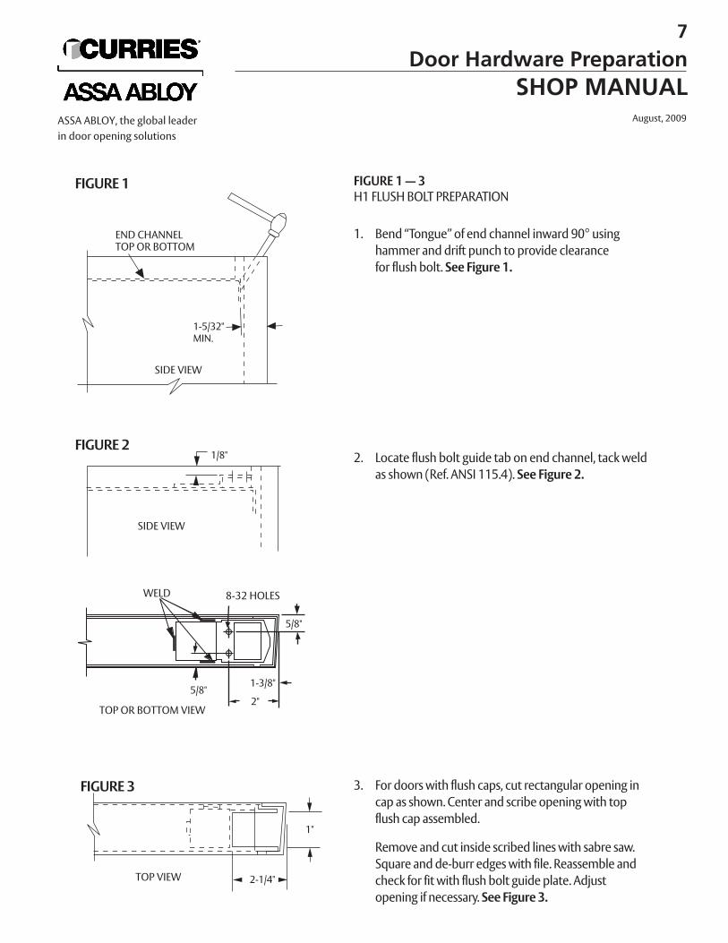
FIGURE 1 — 3H1 FLUSH BOLT PREPARATION
1. Bend “Tongue” of end channel inward 90° usinghammer and drift punch to provide clearancefor flush bolt. See Figure 1.
2. Locate flush bolt guide tab on end channel, tack weldas shown (Ref. ANSI 115.4). See Figure 2.
3. For doors with flush caps, cut rectangular opening incap as shown. Center and scribe opening with topflush cap assembled.
Remove and cut inside scribed lines with sabre saw. Square and de-burr edges with file. Reassemble andcheck for fit with flush bolt guide plate. Adjustopening if necessary. See Figure 3.
FIGURE 1
SIDE VIEW
1-5/32"MIN.
TOP OR BOTTOM VIEW
FIGURE 2
END CHANNELTOP OR BOTTOM
5/8"
1-3/8"
2"
WELD 8-32 HOLES
FIGURE 3
SIDE VIEW
1/8"
2-1/4"
5/8"
TOP VIEW
1"
7
Door Hardware PreparationSHOP MANUAL
August, 2009ASSA ABLOY, the global leaderin door opening solutions
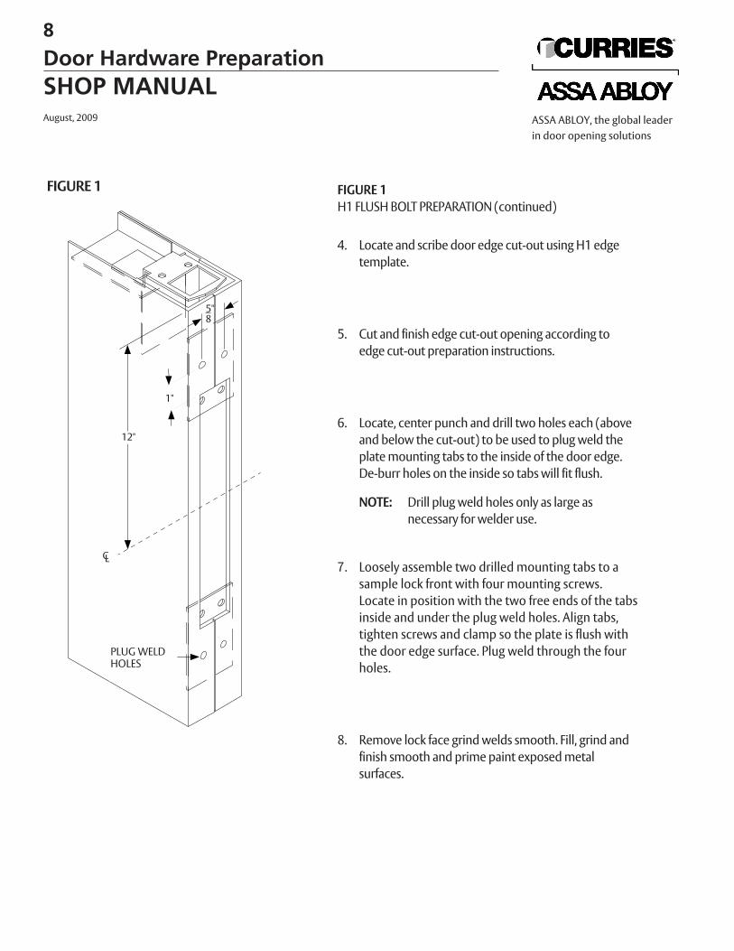
FIGURE 1H1 FLUSH BOLT PREPARATION (continued)
4. Locate and scribe door edge cut-out using H1 edgetemplate.
5. Cut and finish edge cut-out opening according toedge cut-out preparation instructions.
6. Locate, center punch and drill two holes each (aboveand below the cut-out) to be used to plug weld theplate mounting tabs to the inside of the door edge.De-burr holes on the inside so tabs will fit flush.
NOTE: Drill plug weld holes only as large asnecessary for welder use.
7. Loosely assemble two drilled mounting tabs to a sample lock front with four mounting screws.Locate in position with the two free ends of the tabs inside and under the plug weld holes. Align tabs, tighten screws and clamp so the plate is flush with the door edge surface. Plug weld through the four holes.
8. Remove lock face grind welds smooth. Fill, grind andfinish smooth and prime paint exposed metal surfaces.
FIGURE 1
PLUG WELDHOLES
5"8
1"
12"
CL
8
Door Hardware PreparationSHOP MANUALAugust, 2009 ASSA ABLOY, the global leader
in door opening solutions
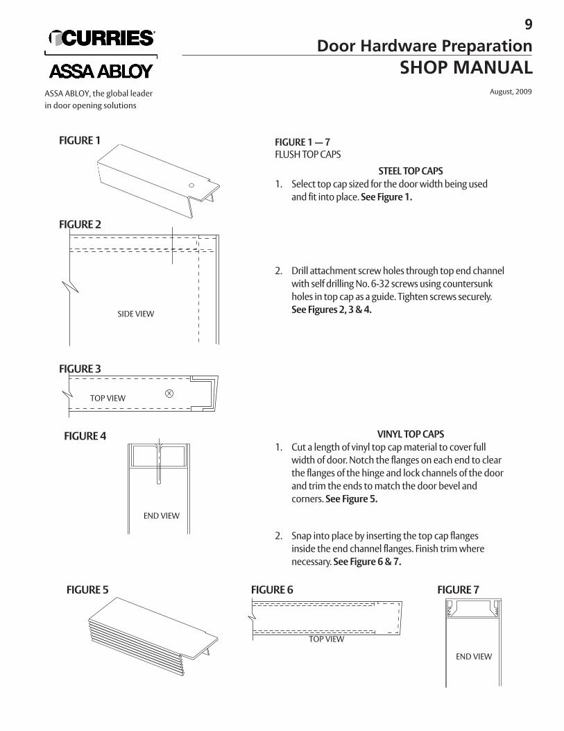
FIGURE 1 — 7FLUSH TOP CAPS
STEEL TOP CAPS1. Select top cap sized for the door width being used
and fit into place. See Figure 1.
2. Drill attachment screw holes through top end channelwith self drilling No. 6-32 screws using countersunkholes in top cap as a guide. Tighten screws securely.See Figures 2, 3 & 4.
VINYL TOP CAPS1. Cut a length of vinyl top cap material to cover full
width of door. Notch the flanges on each end to clearthe flanges of the hinge and lock channels of the doorand trim the ends to match the door bevel and corners. See Figure 5.
2. Snap into place by inserting the top cap flanges inside the end channel flanges. Finish trim wherenecessary. See Figure 6 & 7.
FIGURE 1
FIGURE 2
FIGURE 3
FIGURE 4
FIGURE 5 FIGURE 6 FIGURE 7
SIDE VIEW
TOP VIEW
END VIEW
TOP VIEW
END VIEW
9
Door Hardware PreparationSHOP MANUAL
August, 2009ASSA ABLOY, the global leaderin door opening solutions
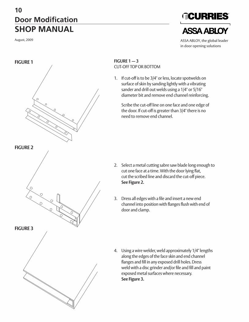
FIGURE 1 — 3CUT-OFF TOP OR BOTTOM
1. If cut-off is to be 3/4" or less, locate spotwelds on surface of skin by sanding lightly with a vibrating sander and drill out welds using a 1/4" or 5/16" diameter bit and remove end channel reinforcing.
Scribe the cut-off line on one face and one edge of the door. If cut-off is greater than 3/4" there is no need to remove end channel.
2. Select a metal cutting sabre saw blade long enough tocut one face at a time. With the door lying flat,cut the scribed line and discard the cut-off piece.See Figure 2.
3. Dress all edges with a file and insert a new endchannel into position with flanges flush with end ofdoor and clamp.
4. Using a wire welder, weld approximately 1/4" lengthsalong the edges of the face skin and end channel flanges and fill in any exposed drill holes. Dressweld with a disc grinder and/or file and fill and paintexposed metal surfaces where necessary.See Figure 3.
FIGURE 1
FIGURE 2
FIGURE 3
10
Door ModificationSHOP MANUALAugust, 2009 ASSA ABLOY, the global leader
in door opening solutions
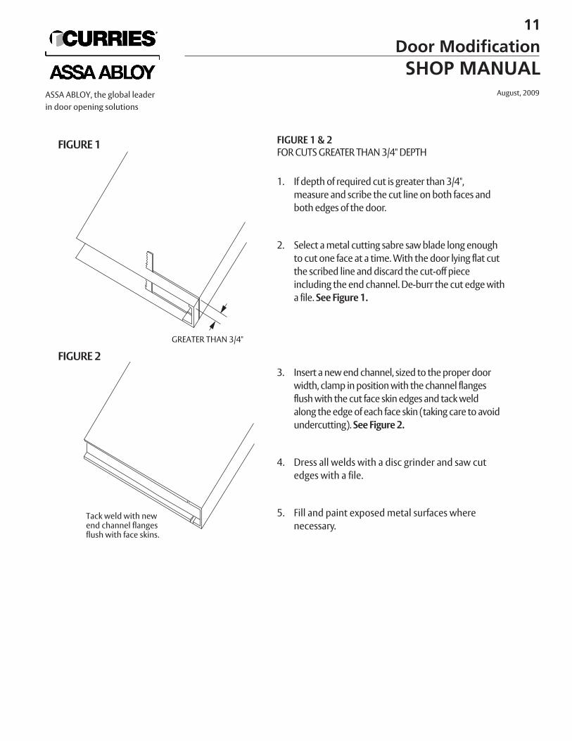
FIGURE 1 & 2FOR CUTS GREATER THAN 3/4" DEPTH
1. If depth of required cut is greater than 3/4",measure and scribe the cut line on both faces andboth edges of the door.
2. Select a metal cutting sabre saw blade long enoughto cut one face at a time. With the door lying flat cutthe scribed line and discard the cut-off piece including the end channel. De-burr the cut edge witha file. See Figure 1.
3. Insert a new end channel, sized to the proper doorwidth, clamp in position with the channel flangesflush with the cut face skin edges and tack weld along the edge of each face skin (taking care to avoidundercutting). See Figure 2.
4. Dress all welds with a disc grinder and saw cutedges with a file.
5. Fill and paint exposed metal surfaces wherenecessary.
FIGURE 1
FIGURE 2GREATER THAN 3/4"
Tack weld with newend channel flangesflush with face skins.
11
Door ModificationSHOP MANUAL
August, 2009ASSA ABLOY, the global leaderin door opening solutions
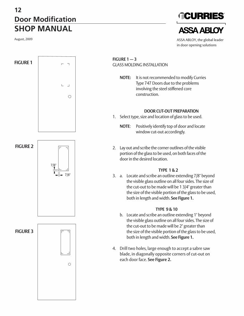
FIGURE 1 — 3GLASS MOLDING INSTALLATION
NOTE: It is not recommended to modify Curries Type 747 Doors due to the problems involving the steel stiffened core construction.
DOOR CUT-OUT PREPARATION1. Select type, size and location of glass to be used.
NOTE: Positively identify top of door and locatewindow cut-out accordingly.
2. Lay out and scribe the corner outlines of the visible portion of the glass to be used, on both faces of the door in the desired location.
TYPE 1 & 23. a. Locate and scribe an outline extending 7/8" beyond
the visible glass outline on all four sides. The size ofthe cut-out to be made will be 1 3/4" greater thanthe size of the visible portion of the glass to be used,both in length and width. See Figure 1.
TYPE 9 & 10b. Locate and scribe an outline extending 1" beyond
the visible glass outline on all four sides. The size ofthe cut-out to be made will be 2" greater thanthe size of the visible portion of the glass to be used,both in length and width. See Figure 1.
4. Drill two holes, large enough to accept a sabre saw blade, in diagonally opposite corners of cut-out oneach door face. See Figure 2.
FIGURE 1
FIGURE 2
FIGURE 3
7/8"
7/8"
12
Door ModificationSHOP MANUALAugust, 2009 ASSA ABLOY, the global leader
in door opening solutions
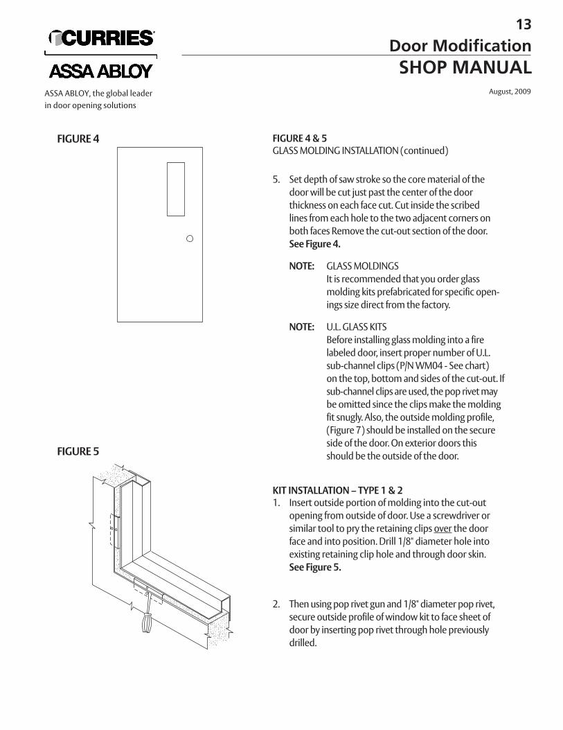
FIGURE 4 & 5GLASS MOLDING INSTALLATION (continued)
5. Set depth of saw stroke so the core material of thedoor will be cut just past the center of the doorthickness on each face cut. Cut inside the scribedlines from each hole to the two adjacent corners onboth faces Remove the cut-out section of the door.See Figure 4.
NOTE: GLASS MOLDINGSIt is recommended that you order glassmolding kits prefabricated for specific open-ings size direct from the factory.
NOTE: U.L. GLASS KITSBefore installing glass molding into a firelabeled door, insert proper number of U.L.sub-channel clips (P/N WM04 - See chart)on the top, bottom and sides of the cut-out. Ifsub-channel clips are used, the pop rivet maybe omitted since the clips make the moldingfit snugly. Also, the outside molding profile,(Figure 7) should be installed on the secureside of the door. On exterior doors this should be the outside of the door.
KIT INSTALLATION – TYPE 1 & 21. Insert outside portion of molding into the cut-out
opening from outside of door. Use a screwdriver orsimilar tool to pry the retaining clips over the doorface and into position. Drill 1/8" diameter hole intoexisting retaining clip hole and through door skin.See Figure 5.
2. Then using pop rivet gun and 1/8" diameter pop rivet,secure outside profile of window kit to face sheet ofdoor by inserting pop rivet through hole previouslydrilled.
FIGURE 4
FIGURE 5
13
Door ModificationSHOP MANUAL
August, 2009ASSA ABLOY, the global leaderin door opening solutions
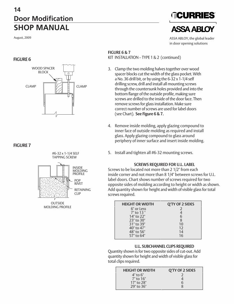
FIGURE 6 & 7KIT INSTALLATION – TYPE 1 & 2 (continued)
3. Clamp the two molding halves together over woodspacer blocks cut the width of the glass pocket. With a No. 36 drill bit, or by using the 6-32 x 1-1/4 selfdrilling screw, drill and install all mounting screwsthrough the countersunk holes provided and into thebottom flange of the outside profile, making surescrews are drilled to the inside of the door face. Thenremove screws for glass installation. Make sure correct number of screws are used for label doors (see Chart). See Figure 6 & 7.
4. Remove inside molding, apply glazing compound toinner face of outside molding as required and installglass. Apply glazing compound to glass around periphery of inner surface and insert inside molding.
5. Install and tighten all #6-32 mounting screws.
SCREWS REQUIRED FOR U.L. LABELScrews to be located not more than 2 1/2" from each inside corner and not more than 8 1/4" between screws for U.L.label doors. Chart shows number of screws required for twoopposite sides of molding according to height or width as shown.Add quantity shown for height and width of visible glass for totalscrews required.
U.L. SUBCHANNEL CLIPS REQUIREDQuantity shown is for two opposite sides of cut-out. Addquantity shown for height and width of visible glass fortotal clips required.
HEIGHT OR WIDTH Q’TY OF 2 SIDES6" or Less 27" to 13 " 4
14" to 22" 623" to 30" 831" to 39" 1040" to 47" 1248" to 56" 1457" to 64" 16
HEIGHT OR WIDTH Q’TY OF 2 SIDES4" to 6" 27" to 16" 4
17" to 28" 629" to 36" 8
FIGURE 6
FIGURE 7
WOOD SPACERBLOCK
CLAMPCLAMP
OUTSIDEMOLDING PROFILE
#6-32 x 1-1/4 SELFTAPPING SCREW
INSIDEMOLDINGPROFILE
POPRIVET
RETAININGCLIP
14
Door ModificationSHOP MANUALAugust, 2009 ASSA ABLOY, the global leader
in door opening solutions
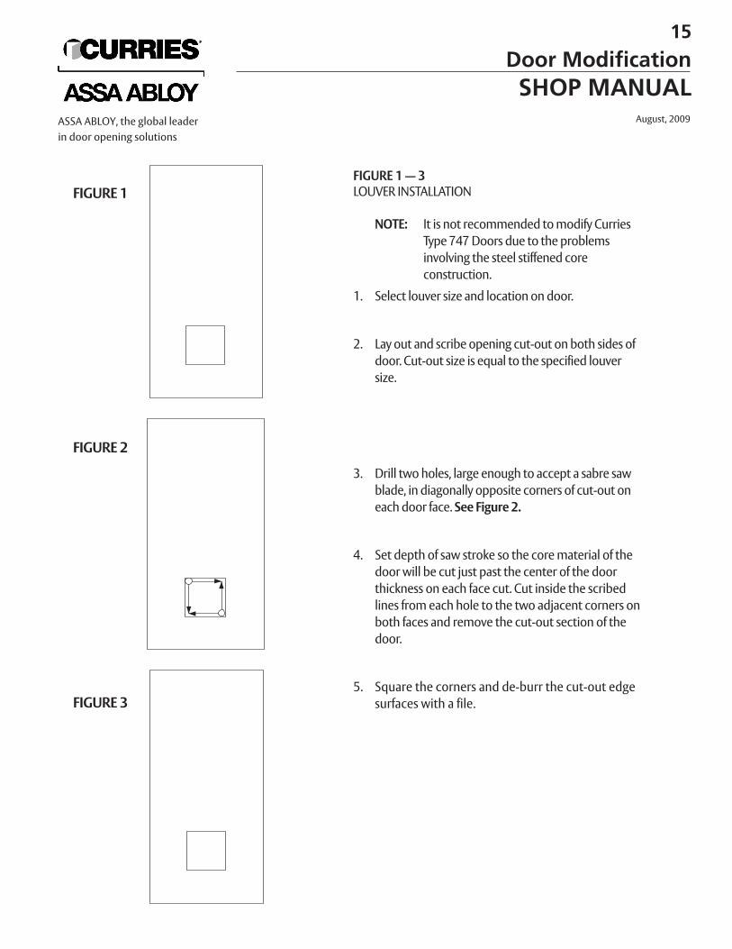
FIGURE 1 — 3LOUVER INSTALLATION
NOTE: It is not recommended to modify CurriesType 747 Doors due to the problems involving the steel stiffened core construction.
1. Select louver size and location on door.
2. Lay out and scribe opening cut-out on both sides ofdoor. Cut-out size is equal to the specified louver size.
3. Drill two holes, large enough to accept a sabre sawblade, in diagonally opposite corners of cut-out oneach door face. See Figure 2.
4. Set depth of saw stroke so the core material of thedoor will be cut just past the center of the doorthickness on each face cut. Cut inside the scribedlines from each hole to the two adjacent corners onboth faces and remove the cut-out section of thedoor.
5. Square the corners and de-burr the cut-out edgesurfaces with a file.
FIGURE 1
FIGURE 2
FIGURE 3
15
Door ModificationSHOP MANUAL
August, 2009ASSA ABLOY, the global leaderin door opening solutions
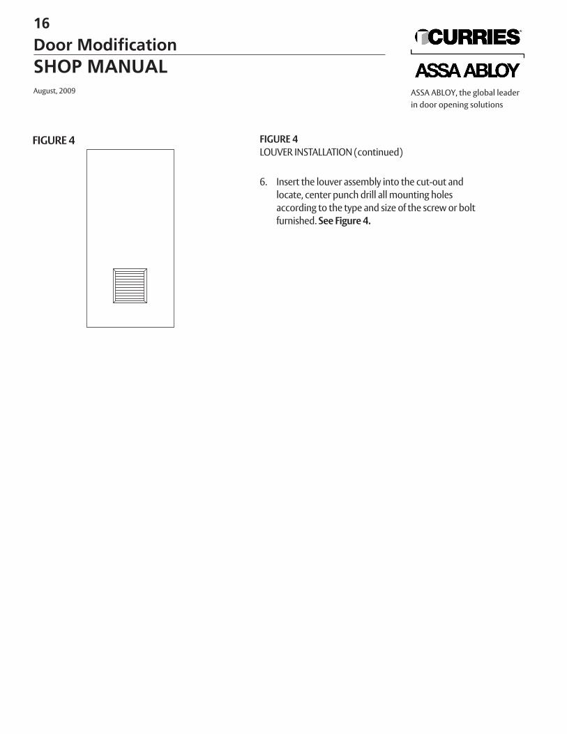
FIGURE 4LOUVER INSTALLATION (continued)
6. Insert the louver assembly into the cut-out and locate, center punch drill all mounting holes according to the type and size of the screw or boltfurnished. See Figure 4.
FIGURE 4
16
Door ModificationSHOP MANUALAugust, 2009 ASSA ABLOY, the global leader
in door opening solutions
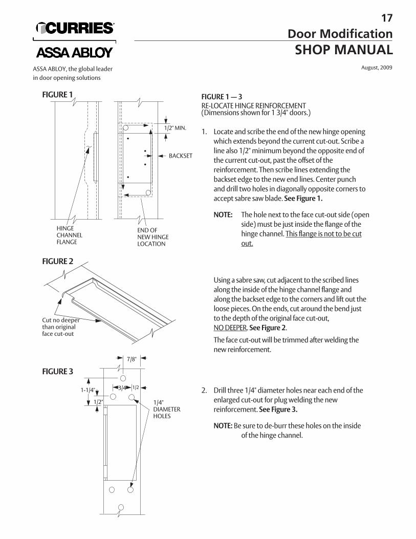
FIGURE 1 — 3RE-LOCATE HINGE REINFORCEMENT(Dimensions shown for 1 3/4" doors.)
1. Locate and scribe the end of the new hinge openingwhich extends beyond the current cut-out. Scribe aline also 1/2" minimum beyond the opposite end ofthe current cut-out, past the offset of the reinforcement. Then scribe lines extending the backset edge to the new end lines. Center punch and drill two holes in diagonally opposite corners toaccept sabre saw blade. See Figure 1.
NOTE: The hole next to the face cut-out side (openside) must be just inside the flange of the hinge channel. This flange is not to be cutout.
Using a sabre saw, cut adjacent to the scribed linesalong the inside of the hinge channel flange andalong the backset edge to the corners and lift out theloose pieces. On the ends, cut around the bend justto the depth of the original face cut-out, NO DEEPER. See Figure 2.
The face cut-out will be trimmed after welding the new reinforcement.
2. Drill three 1/4" diameter holes near each end of theenlarged cut-out for plug welding the new reinforcement. See Figure 3.
NOTE: Be sure to de-burr these holes on the inside of the hinge channel.
FIGURE 1
FIGURE 2
FIGURE 3
HINGECHANNELFLANGE
1/2" MIN.
BACKSET
END OFNEW HINGELOCATION
Cut no deeperthan originalface cut-out
7/8"
1/23/4"1-1/4"
1/2" 1/4"DIAMETERHOLES
17
Door ModificationSHOP MANUAL
August, 2009ASSA ABLOY, the global leaderin door opening solutions
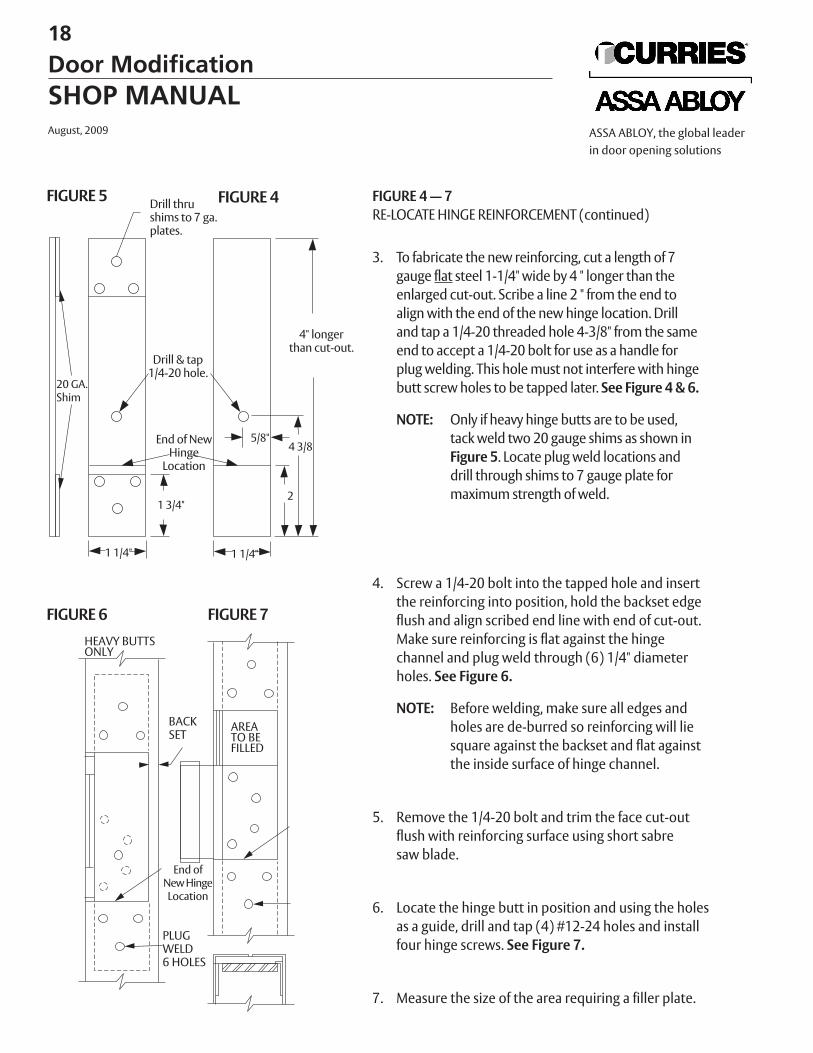
FIGURE 4 — 7RE-LOCATE HINGE REINFORCEMENT (continued)
3. To fabricate the new reinforcing, cut a length of 7 gauge flat steel 1-1/4" wide by 4 " longer than theenlarged cut-out. Scribe a line 2 " from the end toalign with the end of the new hinge location. Drill and tap a 1/4-20 threaded hole 4-3/8" from the sameend to accept a 1/4-20 bolt for use as a handle forplug welding. This hole must not interfere with hingebutt screw holes to be tapped later. See Figure 4 & 6.
NOTE: Only if heavy hinge butts are to be used,tack weld two 20 gauge shims as shown in Figure 5. Locate plug weld locations and drill through shims to 7 gauge plate for maximum strength of weld.
4. Screw a 1/4-20 bolt into the tapped hole and insert the reinforcing into position, hold the backset edgeflush and align scribed end line with end of cut-out.Make sure reinforcing is flat against the hingechannel and plug weld through (6) 1/4" diameterholes. See Figure 6.
NOTE: Before welding, make sure all edges and holes are de-burred so reinforcing will liesquare against the backset and flat againstthe inside surface of hinge channel.
5. Remove the 1/4-20 bolt and trim the face cut-outflush with reinforcing surface using short sabresaw blade.
6. Locate the hinge butt in position and using the holesas a guide, drill and tap (4) #12-24 holes and installfour hinge screws. See Figure 7.
7. Measure the size of the area requiring a filler plate.
FIGURE 5
FIGURE 6
FIGURE 4
FIGURE 7
Drill thrushims to 7 ga.plates.
4" longerthan cut-out.
Drill & tap1/4-20 hole.
End of NewHinge
Location
5/8"4 3/8
21 3/4"
1 1/4"1 1/4"
20 GA.Shim
BACKSET
AREATO BEFILLED
HEAVY BUTTSONLY
End of New HingeLocation
PLUGWELD6 HOLES
18
Door ModificationSHOP MANUALAugust, 2009 ASSA ABLOY, the global leader
in door opening solutions
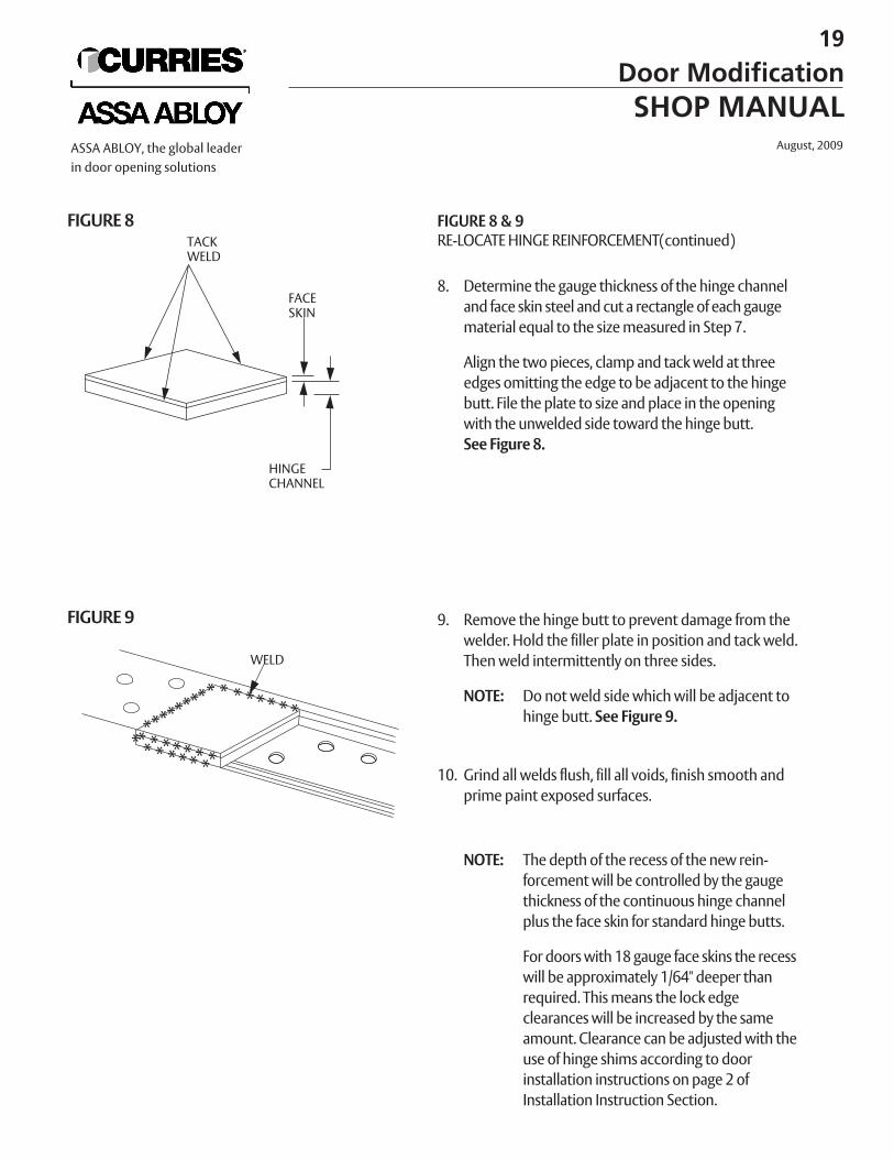
FIGURE 8 & 9RE-LOCATE HINGE REINFORCEMENT(continued)
8. Determine the gauge thickness of the hinge channeland face skin steel and cut a rectangle of each gaugematerial equal to the size measured in Step 7.
Align the two pieces, clamp and tack weld at threeedges omitting the edge to be adjacent to the hingebutt. File the plate to size and place in the opening with the unwelded side toward the hinge butt.See Figure 8.
9. Remove the hinge butt to prevent damage from thewelder. Hold the filler plate in position and tack weld.Then weld intermittently on three sides.
NOTE: Do not weld side which will be adjacent to hinge butt. See Figure 9.
10. Grind all welds flush, fill all voids, finish smooth andprime paint exposed surfaces.
NOTE: The depth of the recess of the new rein-forcement will be controlled by the gaugethickness of the continuous hinge channelplus the face skin for standard hinge butts.
For doors with 18 gauge face skins the recesswill be approximately 1/64" deeper thanrequired. This means the lock edgeclearances will be increased by the sameamount. Clearance can be adjusted with theuse of hinge shims according to doorinstallation instructions on page 2 ofInstallation Instruction Section.
FIGURE 8
FIGURE 9
TACKWELD
FACESKIN
HINGECHANNEL
WELD
19
Door ModificationSHOP MANUAL
August, 2009ASSA ABLOY, the global leaderin door opening solutions
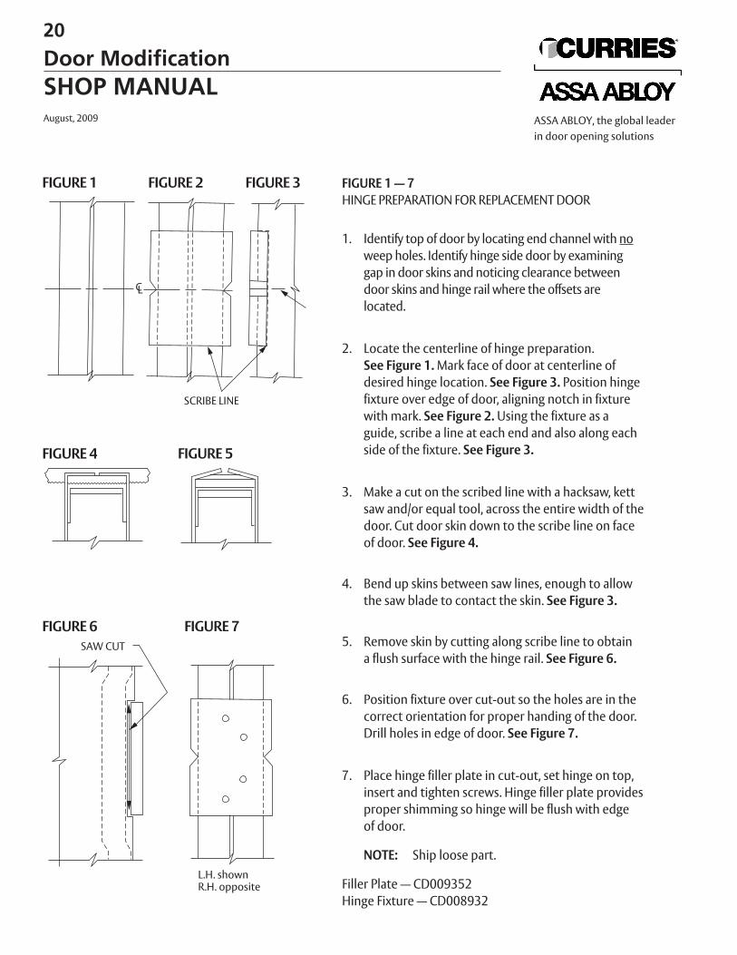
FIGURE 1 — 7HINGE PREPARATION FOR REPLACEMENT DOOR
1. Identify top of door by locating end channel with noweep holes. Identify hinge side door by examininggap in door skins and noticing clearance between door skins and hinge rail where the offsets arelocated.
2. Locate the centerline of hinge preparation. See Figure 1. Mark face of door at centerline ofdesired hinge location. See Figure 3. Position hingefixture over edge of door, aligning notch in fixturewith mark. See Figure 2. Using the fixture as aguide, scribe a line at each end and also along eachside of the fixture. See Figure 3.
3. Make a cut on the scribed line with a hacksaw, kettsaw and/or equal tool, across the entire width of thedoor. Cut door skin down to the scribe line on faceof door. See Figure 4.
4. Bend up skins between saw lines, enough to allow the saw blade to contact the skin. See Figure 3.
5. Remove skin by cutting along scribe line to obtaina flush surface with the hinge rail. See Figure 6.
6. Position fixture over cut-out so the holes are in thecorrect orientation for proper handing of the door.Drill holes in edge of door. See Figure 7.
7. Place hinge filler plate in cut-out, set hinge on top,insert and tighten screws. Hinge filler plate providesproper shimming so hinge will be flush with edgeof door.
NOTE: Ship loose part.
Filler Plate — CD009352Hinge Fixture — CD008932
FIGURE 1
FIGURE 4 FIGURE 5
FIGURE 6 FIGURE 7
FIGURE 2 FIGURE 3
SCRIBE LINE
SAW CUT
L.H. shownR.H. opposite
20
Door ModificationSHOP MANUALAugust, 2009 ASSA ABLOY, the global leader
in door opening solutions
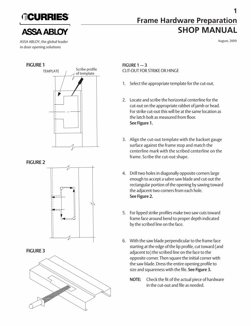
FIGURE 1 — 3CUT-OUT FOR STRIKE OR HINGE
1. Select the appropriate template for the cut-out.
2. Locate and scribe the horizontal centerline for thecut-out on the appropriate rabbet of jamb or head.For strike cut-out this will be at the same location asthe latch bolt as measured from floor.See Figure 1.
3. Align the cut-out template with the backset gaugesurface against the frame stop and match thecenterline mark with the scribed centerline on theframe. Scribe the cut-out shape.
4. Drill two holes in diagonally opposite corners largeenough to accept a sabre saw blade and cut out therectangular portion of the opening by sawing towardthe adjacent two corners from each hole.See Figure 2.
5. For lipped strike profiles make two saw cuts towardframe face around bend to proper depth indicated by the scribed line on the face.
6. With the saw blade perpendicular to the frame facestarting at the edge of the lip profile, cut toward (andadjacent to) the scribed line on the face to the opposite corner. Then square the initial corner with the saw blade. Dress the entire opening profile to size and squareness with the file. See Figure 3.
NOTE: Check the fit of the actual piece of hardware in the cut-out and file as needed.
FIGURE 1
FIGURE 2
FIGURE 3
TEMPLATE Scribe profileof template
1
Frame Hardware PreparationSHOP MANUAL
August, 2009ASSA ABLOY, the global leaderin door opening solutions
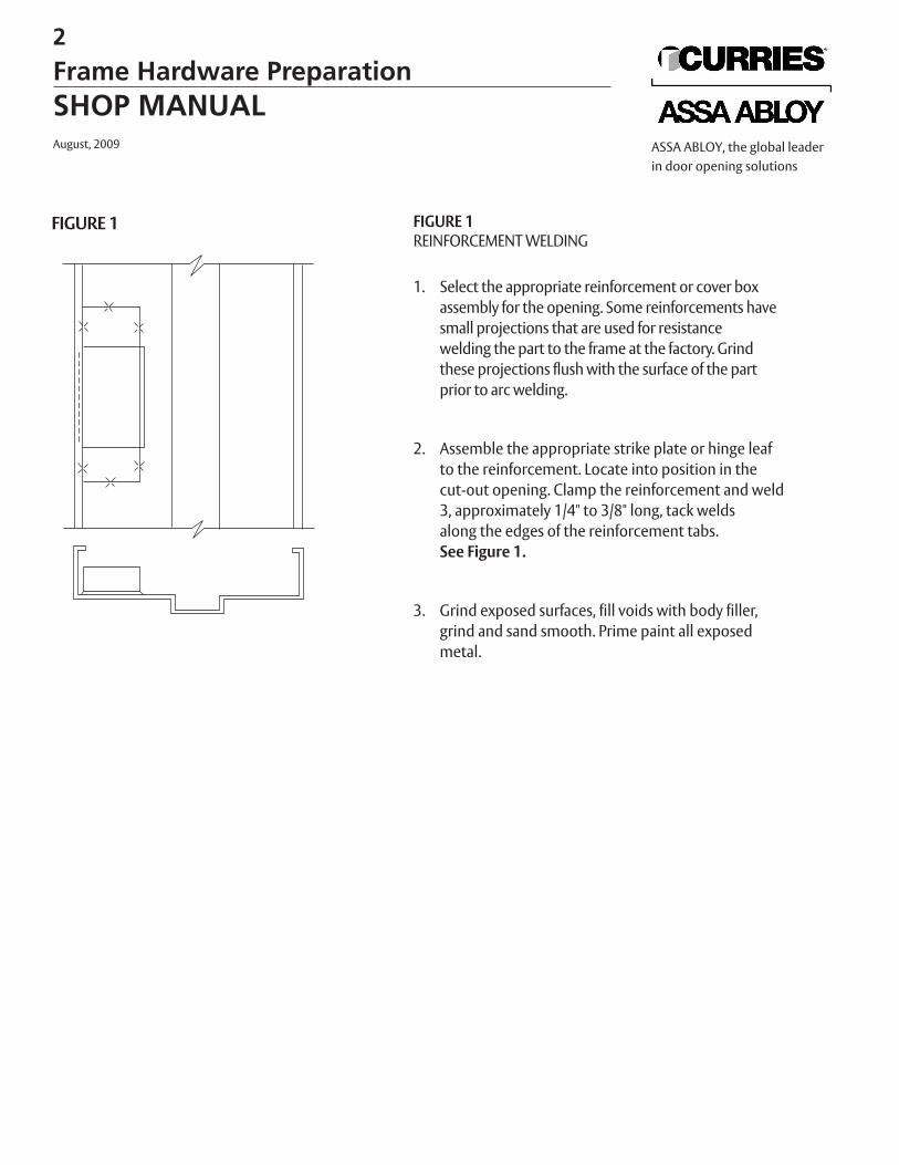
FIGURE 1REINFORCEMENT WELDING
1. Select the appropriate reinforcement or cover boxassembly for the opening. Some reinforcements havesmall projections that are used for resistance welding the part to the frame at the factory. Grindthese projections flush with the surface of the partprior to arc welding.
2. Assemble the appropriate strike plate or hinge leafto the reinforcement. Locate into position in thecut-out opening. Clamp the reinforcement and weld3, approximately 1/4" to 3/8" long, tack weldsalong the edges of the reinforcement tabs.See Figure 1.
3. Grind exposed surfaces, fill voids with body filler, grind and sand smooth. Prime paint all exposed metal.
FIGURE 1
2
Frame Hardware PreparationSHOP MANUALAugust, 2009 ASSA ABLOY, the global leader
in door opening solutions
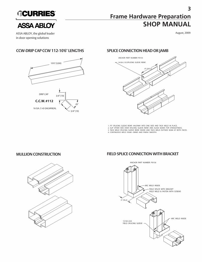
CCW-DRIP CAP CCW 112-10'6" LENGTHS
MULLION CONSTRUCTION
SPLICE CONNECTION HEAD OR JAMB
FIELD SPLICE CONNECTION WITH BRACKET
3
Frame Hardware PreparationSHOP MANUAL
August, 2009ASSA ABLOY, the global leaderin door opening solutions
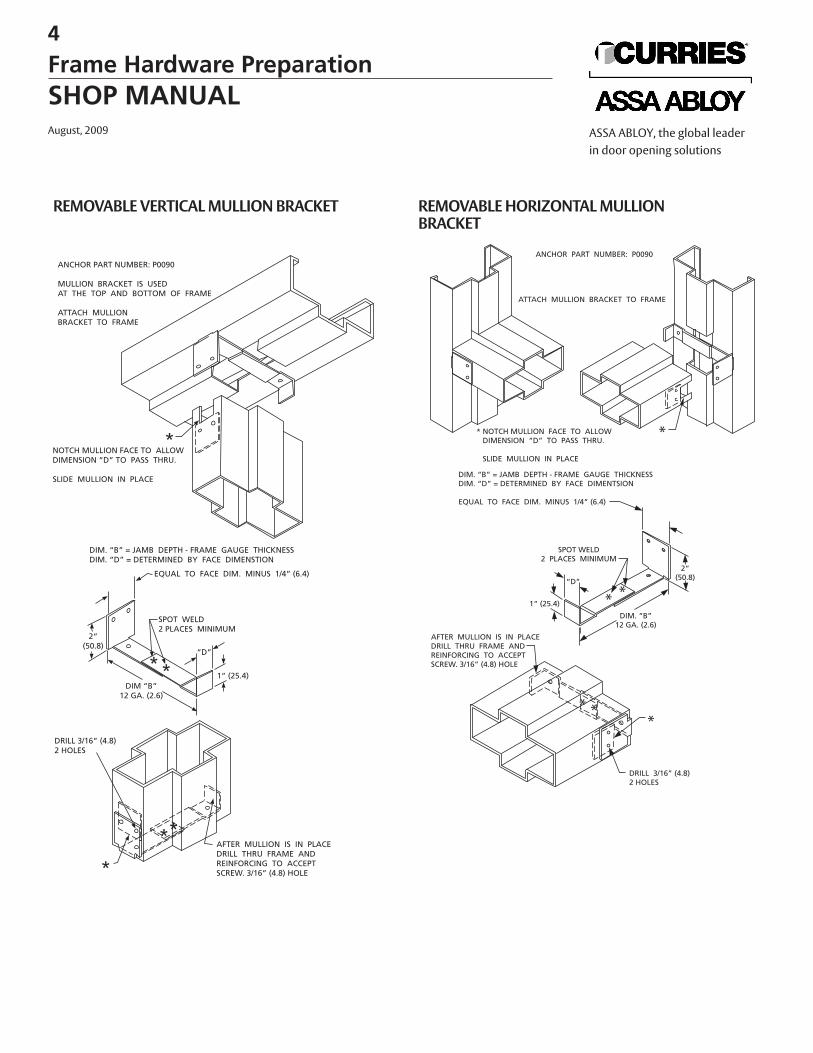
REMOVABLE VERTICAL MULLION BRACKET
“D”
REMOVABLE HORIZONTAL MULLION BRACKET
4
Frame Hardware PreparationSHOP MANUALAugust, 2009 ASSA ABLOY, the global leader
in door opening solutions
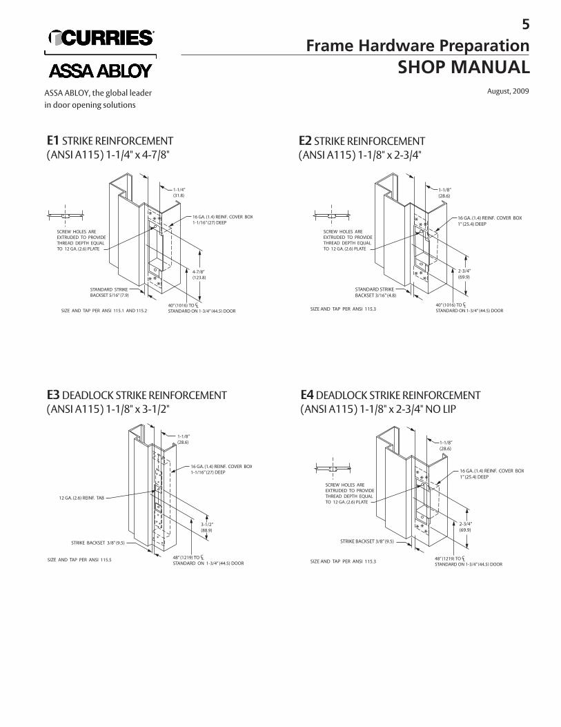
E1 STRIKE REINFORCEMENT(ANSI A115) 1-1/4" x 4-7/8"
E3DEADLOCK STRIKE REINFORCEMENT (ANSI A115) 1-1/8" x 3-1/2"
E4DEADLOCK STRIKE REINFORCEMENT(ANSI A115) 1-1/8" x 2-3/4" NO LIP
E2 STRIKE REINFORCEMENT(ANSI A115) 1-1/8" x 2-3/4"
5
Frame Hardware PreparationSHOP MANUAL
August, 2009ASSA ABLOY, the global leaderin door opening solutions
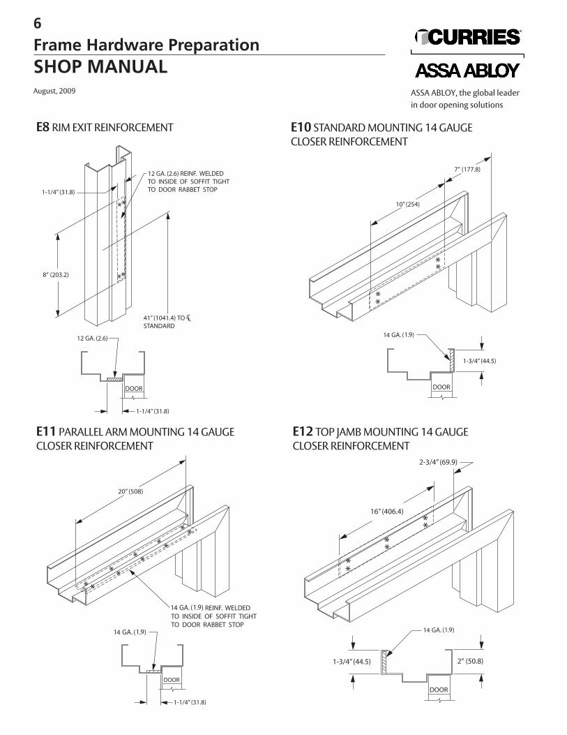
E8 RIM EXIT REINFORCEMENT
E11 PARALLEL ARM MOUNTING 14 GAUGE CLOSER REINFORCEMENT
E12 TOP JAMB MOUNTING 14 GAUGE CLOSER REINFORCEMENT
E10 STANDARD MOUNTING 14 GAUGECLOSER REINFORCEMENT
6
Frame Hardware PreparationSHOP MANUALAugust, 2009 ASSA ABLOY, the global leader
in door opening solutions
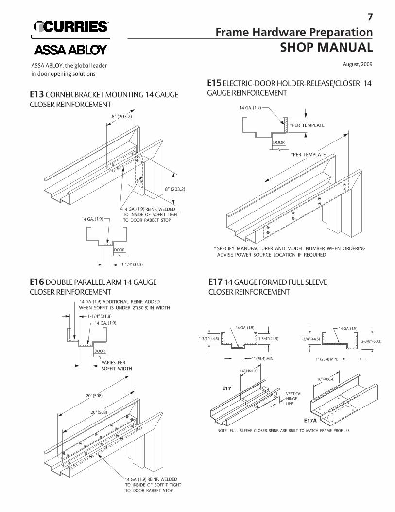
E13CORNER BRACKET MOUNTING 14 GAUGECLOSER REINFORCEMENT
E16DOUBLE PARALLEL ARM 14 GAUGE CLOSER REINFORCEMENT
E17 14 GAUGE FORMED FULL SLEEVE CLOSER REINFORCEMENT
E15 ELECTRIC-DOOR HOLDER-RELEASE/CLOSER 14GAUGE REINFORCEMENT
7
Frame Hardware PreparationSHOP MANUAL
August, 2009ASSA ABLOY, the global leaderin door opening solutions
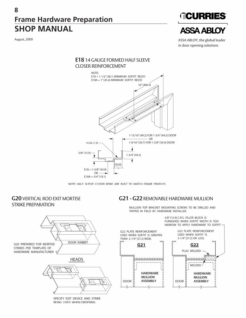
E18 14 GAUGE FORMED HALF SLEEVE CLOSER REINFORCEMENT
G20VERTICAL ROD EXIT MORTISESTRIKE PREPARATION
G21 - G22REMOVABLE HARDWARE MULLION
HARDWAREMULLIONASSEMBLY
HARDWAREMULLIONASSEMBLY
8
Frame Hardware PreparationSHOP MANUALAugust, 2009 ASSA ABLOY, the global leader
in door opening solutions
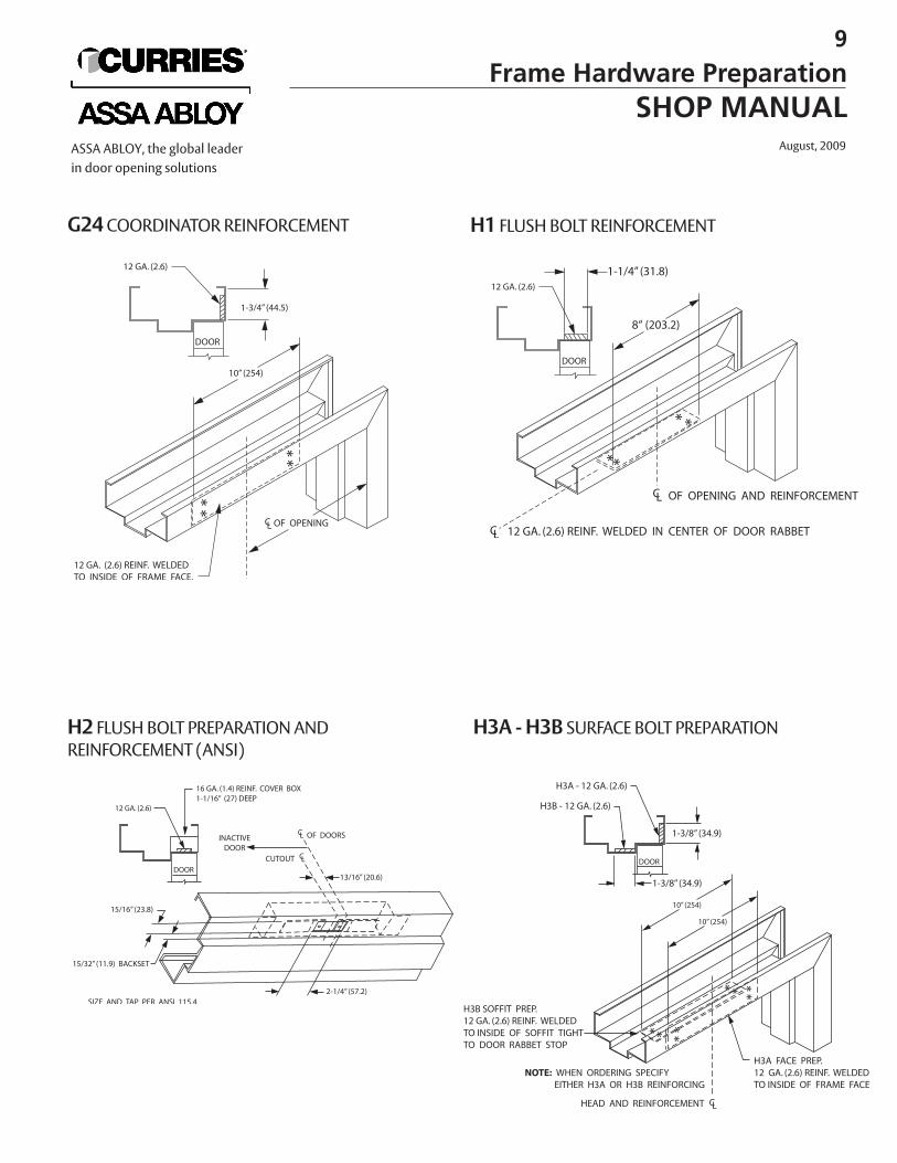
G24COORDINATOR REINFORCEMENT
H2 FLUSH BOLT PREPARATION AND REINFORCEMENT (ANSI)
H3A - H3B SURFACE BOLT PREPARATION
H1 FLUSH BOLT REINFORCEMENT
9
Frame Hardware PreparationSHOP MANUAL
August, 2009ASSA ABLOY, the global leaderin door opening solutions
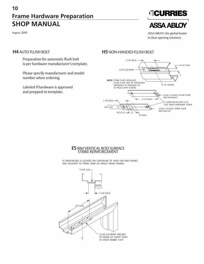
H4AUTO FLUSH BOLT
E5RIM VERTICAL ROD SURFACE STRIKE REINFORCEMENT
E5 REINFORCING IS LOCATED ON CENTERLINE OF HEAD FOR PAIR FRAMESAND ADJACENT TO STRIKE JAMB ON SINGLE SWING FRAMES.
10” (254)
H5NON-HANDED FLUSH BOLTPreparation for automatic flush bolt is per hardware manufacturer’s template.
Please specify manufacturer and model number when ordering.
Labeled if hardware is approvedand prepped to template.
10
Frame Hardware PreparationSHOP MANUALAugust, 2009 ASSA ABLOY, the global leader
in door opening solutions
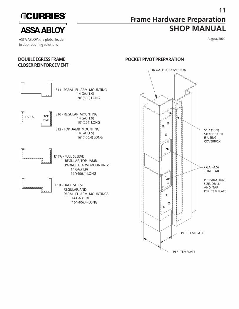
DOUBLE EGRESS FRAME CLOSER REINFORCEMENT
POCKET PIVOT PREPARATION
11
Frame Hardware PreparationSHOP MANUAL
August, 2009ASSA ABLOY, the global leaderin door opening solutions
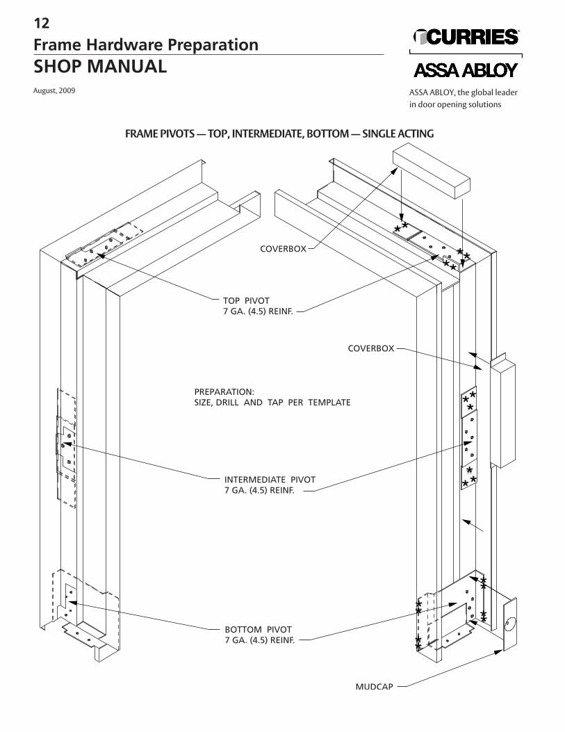
FRAME PIVOTS — TOP, INTERMEDIATE, BOTTOM — SINGLE ACTING
12
Frame Hardware PreparationSHOP MANUALAugust, 2009 ASSA ABLOY, the global leader
in door opening solutions
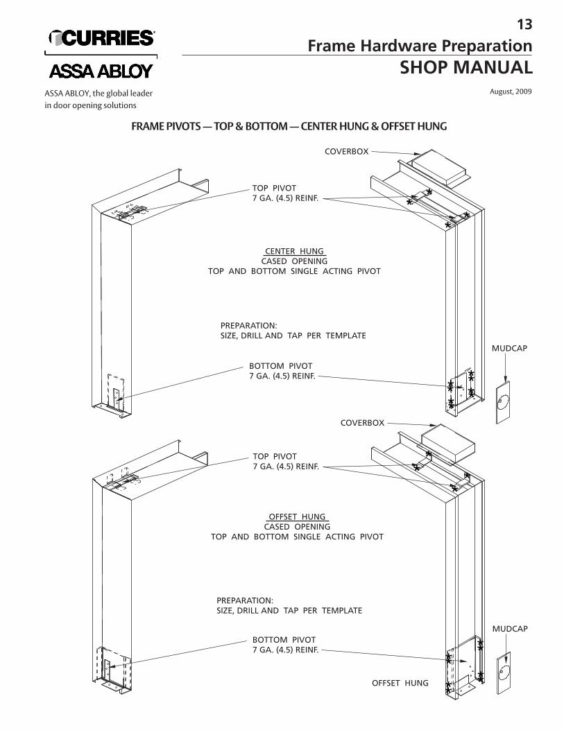
OFFSET HUNG
FRAME PIVOTS — TOP & BOTTOM — CENTER HUNG & OFFSET HUNG
13
Frame Hardware PreparationSHOP MANUAL
August, 2009ASSA ABLOY, the global leaderin door opening solutions
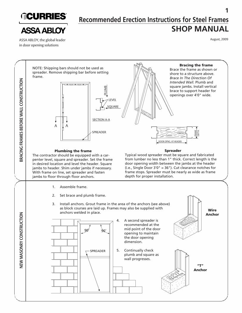
NOTE: Shipping bars should not be used asspreader. Remove shipping bar before settingframe.
Plumbing the frameThe contractor should be equipped with a car-penter level, square and spreader. Set the framein desired location and level the header. Squarejambs to header. Shim under jambs if necessary.With frame on line, set spreader and fastenjambs to floor through floor anchors.
BRAC
ING
FRAM
ES B
EFO
RE W
ALL C
ONS
TRUC
TIO
NNE
W M
ASO
NRY
CONS
TRUC
TIO
N
Bracing the frameBrace the frame as shown orshore to a structure above.Brace In The Direction OfIntended Wall. Plumb andsquare jambs. Install verticalbrace to support header foropenings over 4'0" wide.
SpreaderTypical wood spreader must be square and fabricatedfrom lumber no less than 1" thick. Correct length is thedoor opening width between the jambs at the header(i.e., Single Door 3'0" = 36"). Cut clearance notches forframe stops. Spreader must be nearly as wide as framedepth for proper installation.
A ASPREADER
SECTION A-A
LEVEL
SQUAREPLUMB
DOOR OPNG. AT HEADER
FRAM
EDE
PTH
1. Assemble frame.
2. Set brace and plumb frame.
3. Install anchors. Grout frame in the area of the anchors (see above)as block courses are laid up. Frames may also be supplied withanchors welded in place.
4. A second spreader isrecommended at themid point of the dooropening to maintainthe door openingdimension.
5. Continually checkplumb and square aswall progresses.
WireAnchor
“T”Anchor
90˚ 90˚
SPREADER
1
Recommended Erection Instructions for Steel FramesSHOP MANUAL
August, 2009ASSA ABLOY, the global leaderin door opening solutions
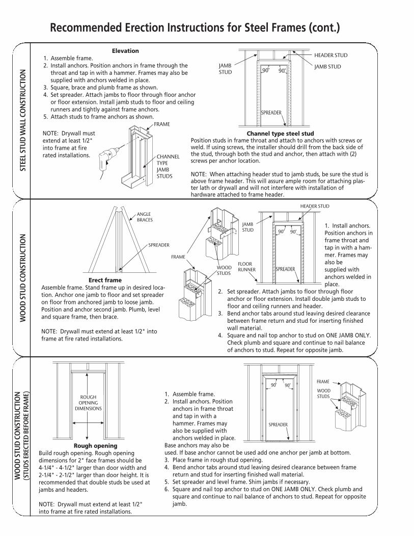
STEE
L STU
D W
ALL C
ONS
TRUC
TIO
NW
OO
D ST
UD C
ONS
TRUC
TIO
NW
OO
D ST
UD C
ONS
TRUC
TIO
N(S
TUDS
EREC
TED
BEFO
RE FR
AME)
Elevation1. Assemble frame.2. Install anchors. Position anchors in frame through the
throat and tap in with a hammer. Frames may also besupplied with anchors welded in place.
3. Square, brace and plumb frame as shown.4. Set spreader. Attach jambs to floor through floor anchor
or floor extension. Install jamb studs to floor and ceilingrunners and tightly against frame anchors.
5. Attach studs to frame anchors as shown.
NOTE: Drywall mustextend at least 1/2"into frame at firerated installations.
Channel type steel studPosition studs in frame throat and attach to anchors with screws orweld. If using screws, the installer should drill from the back side ofthe stud, through both the stud and anchor, then attach with (2)screws per anchor location.
NOTE: When attaching header stud to jamb studs, be sure the stud isabove frame header. This will assure ample room for attaching plas-ter lath or drywall and will not interfere with installation of hardware attached to frame header.
FRAME
CHANNELTYPEJAMBSTUDS
HEADER STUD
JAMBSTUD
SPREADER
90˚ 90˚
Erect frameAssemble frame. Stand frame up in desired loca-tion. Anchor one jamb to floor and set spreaderon floor from anchored jamb to loose jamb.Position and anchor second jamb. Plumb, leveland square frame, then brace.
NOTE: Drywall must extend at least 1/2" intoframe at fire rated installations.
1. Install anchors.Position anchors inframe throat andtap in with a ham-mer. Frames mayalso be supplied withanchors welded inplace.
2. Set spreader. Attach jambs to floor through floor anchor or floor extension. Install double jamb studs to floor and ceiling runners and header.
3. Bend anchor tabs around stud leaving desired clearance between frame return and stud for inserting finished wall material.
4. Square and nail top anchor to stud on ONE JAMB ONLY.Check plumb and square and continue to nail balance of anchors to stud. Repeat for opposite jamb.
ANGLEBRACES
SPREADER
FRAME
WOODSTUDS
FLOORRUNNER
JAMBSTUD
HEADER STUD
SPREADER
90˚ 90˚
Rough openingBuild rough opening. Rough openingdimensions for 2" face frames should be 4-1/4" - 4-1/2" larger than door width and2-1/4" - 2-1/2" larger than door height. It isrecommended that double studs be used atjambs and headers.
NOTE: Drywall must extend at least 1/2"into frame at fire rated installations.
1. Assemble frame.2. Install anchors. Position
anchors in frame throat and tap in with a hammer. Frames may also be supplied with anchors welded in place.
Base anchors may also be used. If base anchor cannot be used add one anchor per jamb at bottom.3. Place frame in rough stud opening.4. Bend anchor tabs around stud leaving desired clearance between frame
return and stud for inserting finished wall material.5. Set spreader and level frame. Shim jambs if necessary.6. Square and nail top anchor to stud on ONE JAMB ONLY. Check plumb and
square and continue to nail balance of anchors to stud. Repeat for opposite jamb.
ROUGHOPENING
DIMENSIONS
SPREADER
90˚ 90˚WOODSTUDS
FRAME
JAMB STUD
Recommended Erection Instructions for Steel Frames (cont.)
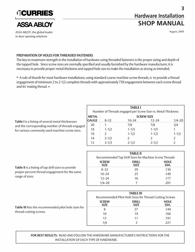
PREPARATION OF HOLES FOR THREADED FASTENERSThe key to maximum strength in the installation of hardware using threaded fasteners is the proper sizing and depth ofthe tapped hole. Since screw sizes are normally specified and usually furnished by the hardware manufacturer, it is necessary to provide proper metal thickness and tapped hole size to make the installation as strong as intended.
- A rule of thumb for most hardware installations, using standard coarse machine screw threads, is to provide a threadengagement of minimum 2 to 2 1/2 complete threads with approximately 75% engagement between each screw threadand its’ mating thread. -
TABLE INumber of Threads engaged per Screw Size vs. Metal Thickness
METAL SCREW SIZEGAUGE 8–32 10–24 12–24 1/4–2020 1 7/8 7/8 3/418 1-1/2 1-1/5 1-1/5 116 2 1-1/2 1-1/2 1-1/214 2-1/2 2 2 212 3-1/3 2-1/2 2-1/2 2
Table I is a listing of several metal thicknessesand the corresponding number of threads engagedfor various commonly used machine screw sizes.
TABLE IIRecommended Tap Drill Sizes for Machine Screw Threads
SCREW DRILL HOLESIZE SIZE DIA.8–32 29 .13610–24 25 .14912–24 16 .1771/4–20 7 .201
Table II is a listing of tap drill sizes to provide proper percent thread engagement for the samerange of sizes.
Table III lists the recommended pilot hole sizes forthread-cutting screws.
TABLE IIIRecommended Pilot Hole Sizes for Thread-Cutting Screws
SCREW DRILL HOLESIZE SIZE DIA.8 27 .14410 19 .16612 11 .1911/4 2 .221
FOR BEST RESULTS: READ AND FOLLOW THE HARDWARE MANUFACTURER’S INSTRUCTIONS FOR THE INSTALLATION OF EACH TYPE OF HARDWARE.
3
Hardware InstallationSHOP MANUAL
August, 2009ASSA ABLOY, the global leaderin door opening solutions
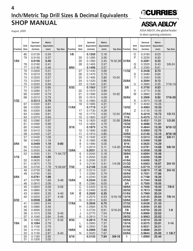
Decimal Metric Decimal Metric Decimal Metric
Drill Equivalent Equivalent Drill Equivalent Equivalent Drill Equivalent Equivalent
Fraction Size (inches) (mm) Tap Size Fraction Size (inches) (mm) Tap Size Fraction Size (inches) (mm) Tap Size
80 0.0135 0.34 1/8 0.1250 3.18 O 0.3160 8.03
79 0.0145 0.37 30 0.1285 3.26 P 0.3230 8.20
1/64 0.0156 0.40 29 0.1360 3.45 “8-32,36” 21/64 0.3281 8.3378 0.0160 0.41 28 0.1405 3.57 Q 0.3320 8.43 3/8-24
77 0.0180 0.46 9/64 0.1406 3.57 R 0.3390 8.61
76 0.0200 0.51 27 0.1440 3.66 11/32 0.3438 8.7375 0.0210 0.53 26 0.1470 3.73 S 0.3480 8.84
74 0.0225 0.57 25 0.1495 3.80 10-24 T 0.3580 9.09
73 0.0240 0.61 24 0.1520 3.86 23/64 0.3594 9.1372 0.0250 0.64 23 0.1540 3.91 U 0.3680 9.35 7/16-14
71 0.0260 0.66 5/32 0.1563 3.97 3/8 0.3750 9.5370 0.0280 0.71 22 0.1570 3.99 V 0.3770 9.58
69 0.0292 0.74 21 0.1590 4.04 10-32 W 0.3860 9.80
68 0.0310 0.79 20 0.1610 4.09 25/64 0.3906 9.92 7/16-201/32 0.0313 0.79 19 0.1660 4.22 X 0.3970 10.08
67 0.0320 0.81 18 0.1695 4.31 Y 0.4040 10.26
66 0.0330 0.84 11/64 0.1719 4.37 13/32 0.4063 10.3265 0.0350 0.89 17 0.1730 4.39 Z 0.4130 10.49
64 0.0360 0.91 16 0.1770 4.50 12-24 27/64 0.4219 10.72 1/2-1363 0.0370 0.94 15 0.1800 4.57 7/16 0.4375 11.1162 0.0380 0.97 14 0.1820 4.62 12-28 29/64 0.4531 11.51 1/2-2061 0.0390 0.99 13 0.1850 4.70 15/32 0.4688 11.9160 0.0400 1.02 3/16 0.1875 4.76 31/64 0.4844 12.30 9/16-1259 0.0410 1.04 12 0.1890 4.80 1/2 0.5000 12.7058 0.0420 1.07 11 0.1910 4.85 33/64 0.5156 13.10 9/16-1857 0.0430 1.09 10 0.1935 4.91 17/32 0.5313 13.49 5/8-1156 0.0465 1.18 9 0.1960 4.98 35/64 0.5469 13.89
3/64 0.0469 1.19 0-80 8 0.1990 5.05 9/16 0.5625 14.2955 0.0520 1.32 7 0.2010 5.11 1/4-20 37/64 0.5781 14.68 5/8-1854 0.0550 1.40 13/64 0.2031 5.16 19/32 0.5938 15.0853 0.0595 1.51 “1-64,72” 6 0.2040 5.18 39/64 0.6094 15.48
1/16 0.0625 1.59 5 0.2055 5.22 5/8 0.6250 15.8852 0.0635 1.61 4 0.2090 5.31 41/64 0.6406 16.2751 0.0670 1.70 3 0.2130 5.41 1/4-28 21/32 0.6563 16.67 3/4-1050 0.0700 1.78 “2-56,64” 7/32 0.2188 5.56 43/64 0.6719 17.0749 0.0730 1.85 2 0.2210 5.61 11/16 0.6875 17.46 3/4-1648 0.0760 1.93 1 0.2280 5.79 45/64 0.7031 17.86
5/64 0.0781 1.98 A 0.2340 5.94 23/32 0.7188 18.2647 0.0785 1.99 3-48 15/64 0.2344 5.95 47/64 0.7344 18.6546 0.0810 2.06 B 0.2380 6.05 3/4 0.7500 19.0545 0.0820 2.08 3-56 C 0.2420 6.15 49/64 0.7656 19.45 7/8-944 0.0860 2.18 D 0.2460 6.25 25/32 0.7813 19.8443 0.0890 2.26 4-40 1/4 E 0.2500 6.35 51/64 0.7969 20.2442 0.0935 2.37 4-48 F 0.2570 6.53 5/16-18 13/16 0.8125 20.64 7/8-14
3/32 0.0938 2.38 G 0.2610 6.63 53/64 0.8281 21.0341 0.0960 2.44 17/64 0.2656 6.75 27/32 0.8438 21.4340 0.0980 2.49 H 0.2660 6.76 55/64 0.8594 21.8339 0.0995 2.53 I 0.2720 6.91 5/16-24 7/8 0.8750 22.23 1-838 0.1015 2.58 5-40 J 0.2770 7.04 57/64 0.8906 22.6237 0.1040 2.64 5-44 K 0.2810 7.14 29/32 0.9063 23.0236 0.1065 2.71 6-32 9/32 0.2813 7.14 59/64 0.9219 23.42
7/64 0.1094 2.78 L 0.2900 7.37 15/16 0.9375 23.81 1-1435 0.1100 2.79 M 0.2950 7.49 61/64 0.9531 24.2134 0.1110 2.82 19/64 0.2969 7.54 31/32 0.9688 24.6133 0.1130 2.87 6-40 N 0.3020 7.67 63/64 0.9844 25.00 1 1/8-732 0.1160 2.95 5/16 0.3125 7.94 3/8-16 1 1.0000 25.4031 0.1200 3.05
4
Inch/Metric Tap Drill Sizes & Decimal EquivalentsSHOP MANUALAugust, 2009 ASSA ABLOY, the global leader
in door opening solutions
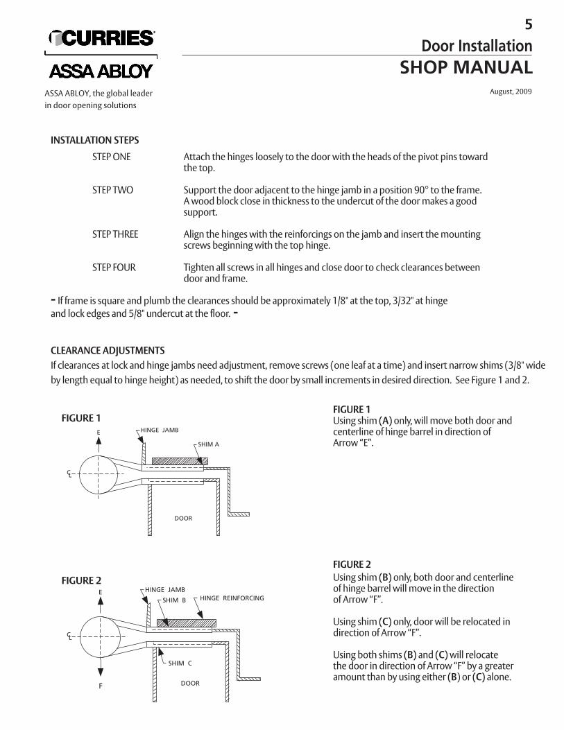
INSTALLATION STEPS
STEP ONE Attach the hinges loosely to the door with the heads of the pivot pins towardthe top.
STEP TWO Support the door adjacent to the hinge jamb in a position 90° to the frame.A wood block close in thickness to the undercut of the door makes a good support.
STEP THREE Align the hinges with the reinforcings on the jamb and insert the mountingscrews beginning with the top hinge.
STEP FOUR Tighten all screws in all hinges and close door to check clearances betweendoor and frame.
- If frame is square and plumb the clearances should be approximately 1/8" at the top, 3/32" at hinge and lock edges and 5/8" undercut at the floor. -
CLEARANCE ADJUSTMENTSIf clearances at lock and hinge jambs need adjustment, remove screws (one leaf at a time) and insert narrow shims (3/8" wideby length equal to hinge height) as needed, to shift the door by small increments in desired direction. See Figure 1 and 2.
FIGURE 1Using shim (A) only, will move both door andcenterline of hinge barrel in direction ofArrow “E”.
FIGURE 2Using shim (B) only, both door and centerlineof hinge barrel will move in the directionof Arrow “F”.
Using shim (C) only, door will be relocated indirection of Arrow “F”.
Using both shims (B) and (C)will relocate the door in direction of Arrow “F” by a greater amount than by using either (B) or (C) alone.
FIGURE 1
FIGURE 2
5
Door InstallationSHOP MANUAL
August, 2009ASSA ABLOY, the global leaderin door opening solutions
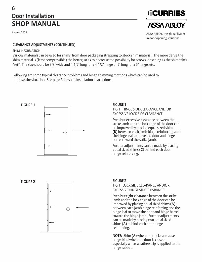
CLEARANCE ADJUSTMENTS (CONTINUED)
SHIM INFORMATIONVarious materials can be used for shims, from door packaging strapping to stock shim material. The more dense theshim material is (least compressible) the better, so as to decrease the possibility for screws loosening as the shim takes“set”. The size should be 3/8" wide and 4-1/2" long for a 4-1/2" hinge or 5" long for a 5" hinge, etc.
Following are some typical clearance problems and hinge shimming methods which can be used to improve the situation. See page 3 for shim installation instructions.
FIGURE 1TIGHT HINGE SIDE CLEARANCE AND/OREXCESSIVE LOCK SIDE CLEARANCE
Even but excessive clearance between the strike jamb and the lock edge of the door canbe improved by placing equal sized shims (B) between each jamb hinge reinforcing andthe hinge leaf to move the door and hinge barrel toward the strike jamb.
Further adjustments can be made by placingequal sized shims (C) behind each doorhinge reinforcing.
FIGURE 2TIGHT LOCK SIDE CLEARANCE AND/OREXCESSIVE HINGE SIDE CLEARANCE
Even but tight clearance between the strikejamb and the lock edge of the door can beimproved by placing equal sized shims (A)between each jamb hinge reinforcing and thehinge leaf to move the door and hinge barrel toward the hinge jamb. Further adjustmentscan be made by placing two equal sized shims (A) behind each door hinge reinforcing.
NOTE: Shim (A) when too thick can causehinge bind when the door is closed, especially when weatherstrip is applied to thehinge rabbet.
FIGURE 1
FIGURE 2
6
Door InstallationSHOP MANUALAugust, 2009 ASSA ABLOY, the global leader
in door opening solutions
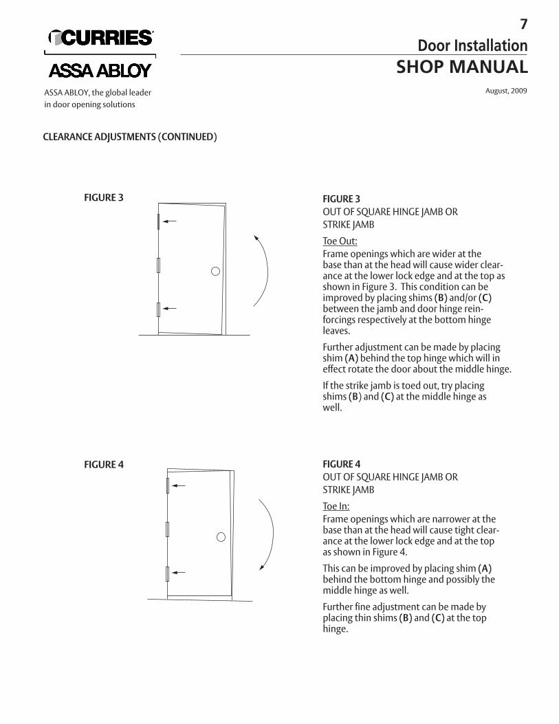
CLEARANCE ADJUSTMENTS (CONTINUED)
FIGURE 3OUT OF SQUARE HINGE JAMB OR STRIKE JAMB
Toe Out:Frame openings which are wider at the base than at the head will cause wider clear-ance at the lower lock edge and at the top as shown in Figure 3. This condition can beimproved by placing shims (B) and/or (C)between the jamb and door hinge rein-forcings respectively at the bottom hinge leaves.
Further adjustment can be made by placingshim (A) behind the top hinge which will ineffect rotate the door about the middle hinge.
If the strike jamb is toed out, try placingshims (B) and (C) at the middle hinge as well.
FIGURE 4OUT OF SQUARE HINGE JAMB ORSTRIKE JAMB
Toe In:Frame openings which are narrower at thebase than at the head will cause tight clear-ance at the lower lock edge and at the topas shown in Figure 4.
This can be improved by placing shim (A)behind the bottom hinge and possibly the middle hinge as well.
Further fine adjustment can be made byplacing thin shims (B) and (C) at the tophinge.
FIGURE 3
FIGURE 4
7
Door InstallationSHOP MANUAL
August, 2009ASSA ABLOY, the global leaderin door opening solutions
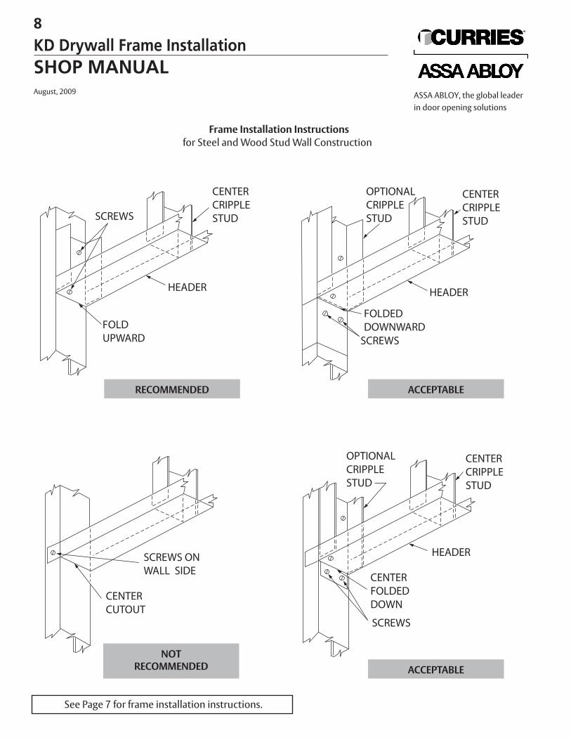
Frame Installation Instructionsfor Steel and Wood Stud Wall Construction
See Page 7 for frame installation instructions.
RECOMMENDED ACCEPTABLE
ACCEPTABLENOT
RECOMMENDED
8
KD Drywall Frame InstallationSHOP MANUALAugust, 2009 ASSA ABLOY, the global leader
in door opening solutions
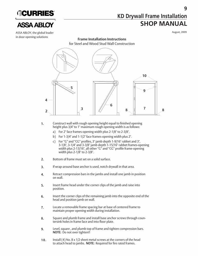
Frame Installation Instructionsfor Steel and Wood Stud Wall Construction
1. Construct wall with rough opening height equal to finished openingheight plus 3/4" to 1" maximum rough opening width is as follows:a) For 2" face frames-opening width plus 2-1/8" to 2-3/8".b) For 1-3/4" and 1-1/2" face frames-opening width plus 2".c) For “G” and “CG” profiles, 3" jamb depth 1-9/16" rabbet and 3",
3-1/8", 3-1/4" and 3-3/8" jamb depth 1-15/16" rabbet frames-openingwidth plus 2-13/16", all other “G” and “CG” profile frame-openingwidth plus 2-1/8" to 2-3/8".
2. Bottom of frame must set on a solid surface.
3. If wrap-around base anchor is used, notch drywall in that area.
4. Retract compression bars in the jambs and install one jamb in position on wall.
5. Insert frame head under the corner clips of the jamb and raise intoposition.
6. Insert the corner clips of the remaining jamb into the opposite end of thehead and position jamb on wall.
7. Locate a removable frame spacing bar at base of centered frame tomaintain proper opening width during installation.
8. Square and plumb frame and install base anchor screws through coun-tersink holes in frame face and into floor plate.
9. Level, square , and plumb top of frame and tighten compression bars. NOTE: Do not over tighten!!
1 0 . Install (4) No. 8 x 1/2 sheet metal screws at the corners of the headto attach head to jambs. NOTE: Required for fire rated frames.
3
4
5
6
10
9
7 88
9
KD Drywall Frame InstallationSHOP MANUAL
August, 2009ASSA ABLOY, the global leaderin door opening solutions
2
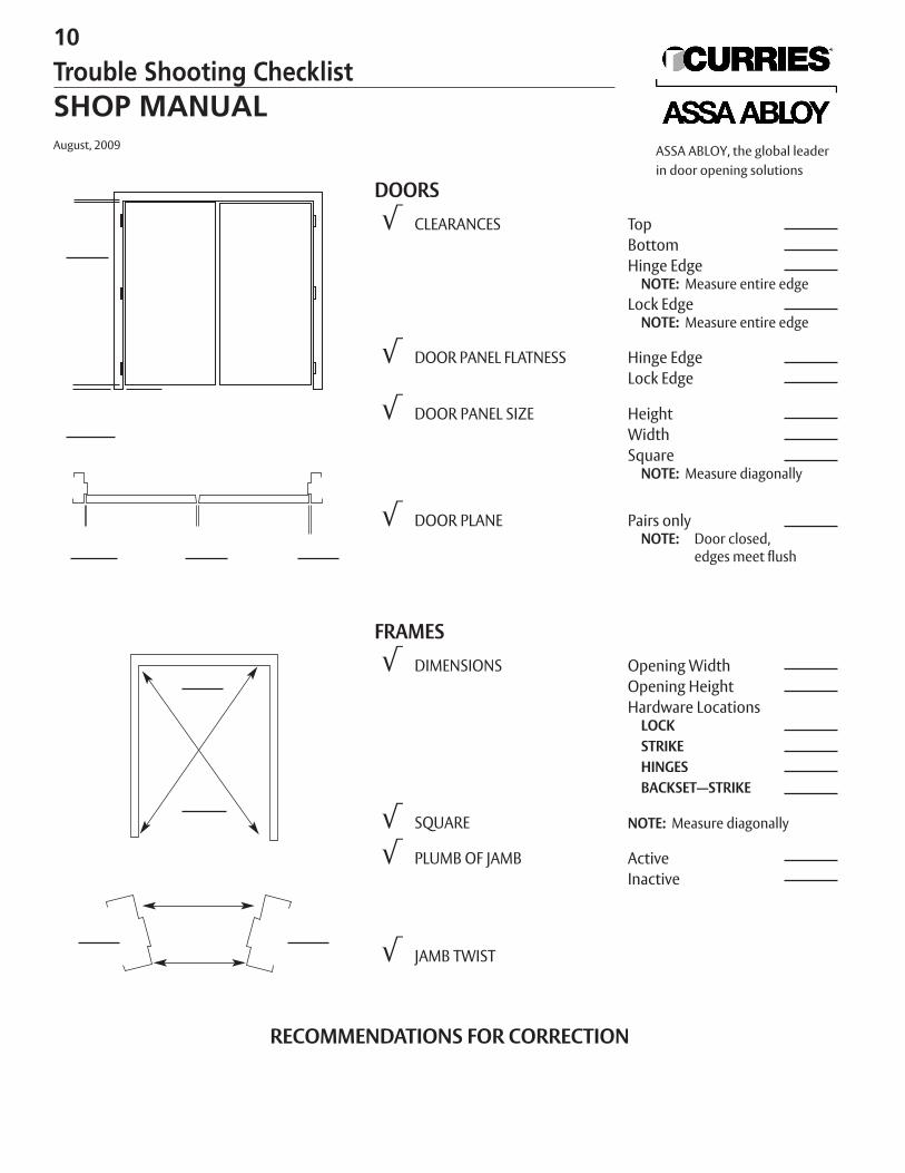
RECOMMENDATIONS FOR CORRECTION
DOORS√ CLEARANCES Top
BottomHinge Edge
NOTE: Measure entire edgeLock Edge
NOTE: Measure entire edge
√ DOOR PANEL FLATNESS Hinge EdgeLock Edge
√ DOOR PANEL SIZE HeightWidthSquare
NOTE: Measure diagonally
√ DOOR PLANE Pairs onlyNOTE: Door closed,
edges meet flush
FRAMES√ DIMENSIONS Opening Width
Opening HeightHardware Locations
LOCkSTRIkEHINGESBACkSET—STRIkE
√ SQUARE NOTE: Measure diagonally
√ PLUMB OF JAMB ActiveInactive
√ JAMB TWIST
10
Trouble Shooting ChecklistSHOP MANUALAugust, 2009 ASSA ABLOY, the global leader
in door opening solutions
The most frequent cause of poor door and frame fitting is improperly assembled or inadequatelyinstalled frames. Since most complaints received are not explicit as to the actual cause of the prob-lem, but rather the results of the problem, it becomes necessary to analyze the situations systemat-ically to determine the best course of action.
Proper inspection of an installation requires the use of certain tools which will facilitate consistent accurate measurement for best results. The following list includes the mini-mum basic equipment which will be needed:
1. Steel Tape: Measure doors and frame openings anddiagonals as a double check for squareness.
2. Framing Square: Determine squareness of frame and doublecheck for jamb twist.
3. Solid Steel Rule: 4 ft.—Check for jamb twist in single doorframes.
4. 6 ft. Masonry Level: Determine level of head, plumb of jambs and to check for bow in doors.
5. Plumb Bob and Line: Double check plumb of jambs.
Experience with trouble shooting and correcting door/frame installation problems willundoubtedly lead to other methods and devices to help make the job easier.
Regardless of the type of complaint, it will be advantageous to obtain all the data possible thatcan reveal any indication of improper installation or distorted door or frame parts. In the caseof drywall frames make sure the frame fits the wall section without spreading the throat orwithout undue clearance. Too tight a fit can cause distortion and dislocation of the rabbetswhich in turn can decrease available door to frame clearances on the lock edge. Also this willcause poor fitting miter joints in knockdown or KD frames.
Masonry frames are normally installed and anchored to the concrete floorbefore the wall is built. They are then anchored to the wall between courses and often filledwith mortar. It is obvious that initial alignment of a masonry frame is critical and that suffi-cient support must be given to prevent distortion due to the accumulated weight of wet mor-tar. If a spacer is not placed in the opening between the jambs at the mid-point, as well as atthe floor during this process there will likely be a degree of bow and possibly twist in thejambs. This will, in the very least, decrease available door to frame clearance.
Table 1, on pages 10 and 11, is a guide that can be followed to collect pertinent data necessary to analyze an installation problem.
Following Table 1 are recommended corrections for doors suspected of being twistedor bowed (see pages 12 and 13).
SystematicallyAnalyze
Basic Equipment List
Too Tight a Fit
Masonry Alignment
Table 1
11
Trouble Shooting - Door and Frame InstallationsSHOP MANUAL
August, 2009ASSA ABLOY, the global leaderin door opening solutions
SINGLE DOOR FRAMES1. With doors closed, measure
clearances at head andboth jambs.Head 1/8"Jamb 3/32"Undercut (1-3/4" Door) 5/8"Undercut (1-3/8" Door) 3/4"
2. With door closed, observewhether door rest flush on stops of jamb and head.
3. With door ajar, observewhether door will remain stationary or swing open or close involuntarily.
4. With door open, place fram-ing square in corner against jamb and head rabbets to determine squareness of both jambs with head. Measure opening width at head and at floor.
5. Measurewith steel tape diagonally from corner tocorner of opening in bothdirections and on both sidesof frame.
6. Determine plumb of both jambs using the 6 ft. levelvertically on the jamb facesor by suspending a plumbbob on a line against the head face and adjacent toeach jamb.
PAIR OF DOORS/FRAMESWith doors closed, measureclearances at head, both jambs andbetween doors.
Head 1/8"Jamb 3/32"Center 3/16"
(1/8" with “Z” astragal)Intermediate Mullion 3/32"Undercut (1-3/4" Door) 5/8"Undercut (1-3/8" Door) 3/4"
With doors closed, observewhether they are flush with each otherat meeting edges or with stops of inter-mediate mullion.
With doors ajar, observewhetherthey will remain stationary orswing open or close involuntarily.
With doors open, place framing square in corner against jamband head rabbets to determinesquareness of both jambs andintermediate mullion (if used) withhead. Measure opening width at headand floor.
Measurewith steel tape diagonally from corner to cornerof opening in both direction and on both sides of frame. On frames withintermediate mullions do this for bothdoor openings plus over the full frameopening.
Determine plumb of both jambs and intermediate mullion (if applica-ble) using the 6 ft. level vertically onthe jamb or mullion faces or by sus-pending a plumb bob on a line againstthe head face and adjacent to eachjamb or mullion.
REMARkSInconsistent clearances on a given side indicate likely out ofsquare frames or twisted jambsor improperly seated hingesor reinforcings.
Incomplete contact with stopfor single doors or uneven meeting edges for pairs ofdoors indicate out of plumb ortwisted jambs or both.
Involuntary movement of doors indicate out of plumb ortwisted jambs or both.Out of square jambs and heads willcause inconsistent clearances orinterference between door and jambor head or between meeting edgesof pairs of doors.
If diagonal measurements areidentical the frame opening issquare. This procedure canconfirm indications observedper Step 4.
Evaluation of plumb should bedone in conjunction with evaluation for twist because the lat-ter can affect the plumbindication, depending upon thedegree of twist. Both jambs shouldgive precisely identical readings on alevel bubble. If there is any question,confirm the reading using a plumbbob.
12
Trouble Shooting Guide for Door InstallationsSHOP MANUALAugust, 2009 ASSA ABLOY, the global leader
in door opening solutions
SINGLE DOOR FRAMES7. Check for jamb twist by layingthe framing square flat on the flooragainst the rabbet or face and mark aline on the floor toward the oppositejamb. Repeat for both jambs.NOTE: A 4 ft. steel ruler simulta-neously placed against the faces ofopposite jambs will verify results.
PAIR OF DOORS/FRAMESCheck for jamb twist by laying theframing square flat on floor against therabbet or face and mark a line on thefloor toward the opposite jamb. Repeatfor both jambs and both sides of theintermediate mullion if applicable.
REMARkSThe extended lines should meet asone straight line if both jambs are inplumb and without twist or theyshould be parallel if there is no twistbut some out of plumb.
CHECkING DOORS SUSPECTED OF BEING TWISTED OR BOWED
Single doors which do not fit flush against the stop of the strike jamb or pairsof doors which are not flush at the meeting edges could contain twist or bow. This can bedetermined with the door in its hung position by placing a 6 ft. level vertically against theface of the door adjacent to the lock edge. Any bow or twist in the door will be evident ifthe level will not lie flat against the door over its entire length. It is important that a mini-mum 6 ft. level be used to adequately indicate bow or twist.
If no deformation of the door is indicated, check the plumb of the lock edge with the door in its closed position. If it will not latch, hold it without forcing it against theframe stop. Compare the plumb of the door with the plumb of the hinge and strike jambsfor single doors, or with both hinge jambs for pairs of doors. If the plumb of the door edgeis identical with the hinge jamb, even though they may not be vertical, this would confirmthat no twist or bow exists. Further, if the hinge and/or strike jamb are out of plumb thiswould confirm the cause of the door not fitting properly.
Methods to correct door and frame fitting problems are on page 12 and 13.
13
Trouble Shooting Guide for Door and Frame InstallationsSHOP MANUAL
August, 2009ASSA ABLOY, the global leaderin door opening solutions
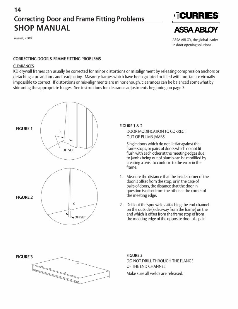
CORRECTING DOOR & FRAME FITTING PROBLEMS
CLEARANCESKD drywall frames can usually be corrected for minor distortions or misalignment by releasing compression anchors ordetaching stud anchors and readjusting. Masonry frames which have been grouted or filled with mortar are virtuallyimpossible to correct. If distortions or mis-alignments are minor enough, clearances can be balanced somewhat byshimming the appropriate hinges. See instructions for clearance adjustments beginning on page 3.
FIGURE 1 & 2DOOR MODIFICATION TO CORRECTOUT-OF-PLUMB JAMBS
Single doors which do not lie flat against the frame stops, or pairs of doors which do not fitflush with each other at the meeting edges dueto jambs being out of plumb can be modified bycreating a twist to conform to the error in theframe.
1. Measure the distance that the inside corner of thedoor is offset from the stop, or in the case ofpairs of doors, the distance that the door in question is offset from the other at the corner of the meeting edge.
2. Drill out the spot welds attaching the end channel on the outside (side away from the frame) on theend which is offset from the frame stop of fromthe meeting edge of the opposite door of a pair.
FIGURE 3DO NOT DRILL THROUGH THE FLANGE OF THE END CHANNEL
Make sure all welds are released.
FIGURE 1
FIGURE 2
FIGURE 3
14
Correcting Door and Frame Fitting ProblemsSHOP MANUALAugust, 2009 ASSA ABLOY, the global leader
in door opening solutions
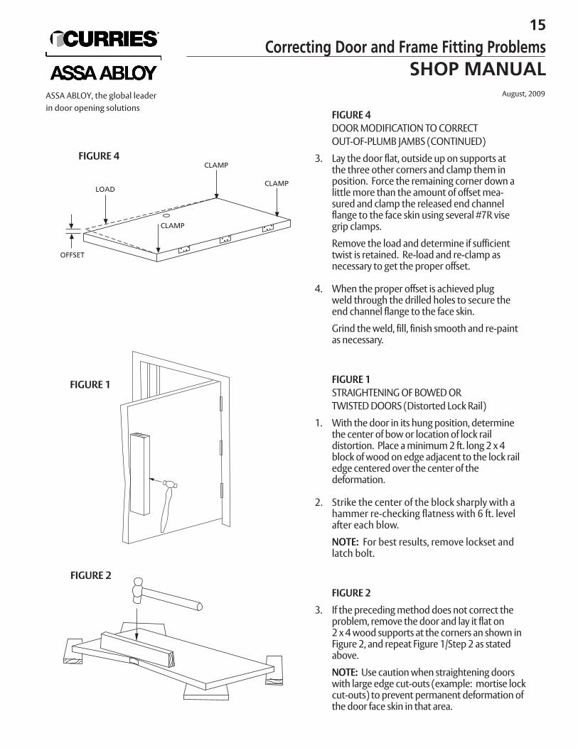
FIGURE 4DOOR MODIFICATION TO CORRECT OUT-OF-PLUMB JAMBS (CONTINUED)
3. Lay the door flat, outside up on supports at the three other corners and clamp them in position. Force the remaining corner down alittle more than the amount of offset mea-sured and clamp the released end channel flange to the face skin using several #7R visegrip clamps.
Remove the load and determine if sufficienttwist is retained. Re-load and re-clamp asnecessary to get the proper offset.
4. When the proper offset is achieved plug weld through the drilled holes to secure theend channel flange to the face skin.
Grind the weld, fill, finish smooth and re-paintas necessary.
FIGURE 1STRAIGHTENING OF BOWED OR TWISTED DOORS (Distorted Lock Rail)
1. With the door in its hung position, determine the center of bow or location of lock rail distortion. Place a minimum 2 ft. long 2 x 4 block of wood on edge adjacent to the lock railedge centered over the center of the deformation.
2. Strike the center of the block sharply with a hammer re-checking flatness with 6 ft. level after each blow.
NOTE: For best results, remove lockset and latch bolt.
FIGURE 2
3. If the preceding method does not correct the problem, remove the door and lay it flat on 2 x 4 wood supports at the corners an shown inFigure 2, and repeat Figure 1/Step 2 as stated above.
NOTE: Use caution when straightening doorswith large edge cut-outs (example: mortise lockcut-outs) to prevent permanent deformation of the door face skin in that area.
FIGURE 4
FIGURE 1
FIGURE 2
15
Correcting Door and Frame Fitting ProblemsSHOP MANUAL
August, 2009ASSA ABLOY, the global leaderin door opening solutions
PACKAGING AND PRODUCT LABELING
Doors and frames are packaged and shipped to minimize damage in transit.Packaging depends on how materials are ordered. Your sales manager or cus-tomer service representative can help you with coordinating orders for bestpackaging and shipping results.
All products are identified with a label tag. A brief description of a door andframe tag follows on the next pages.
7
MiscellaneousSHOP MANUAL
August, 2009ASSA ABLOY, the global leaderin door opening solutions
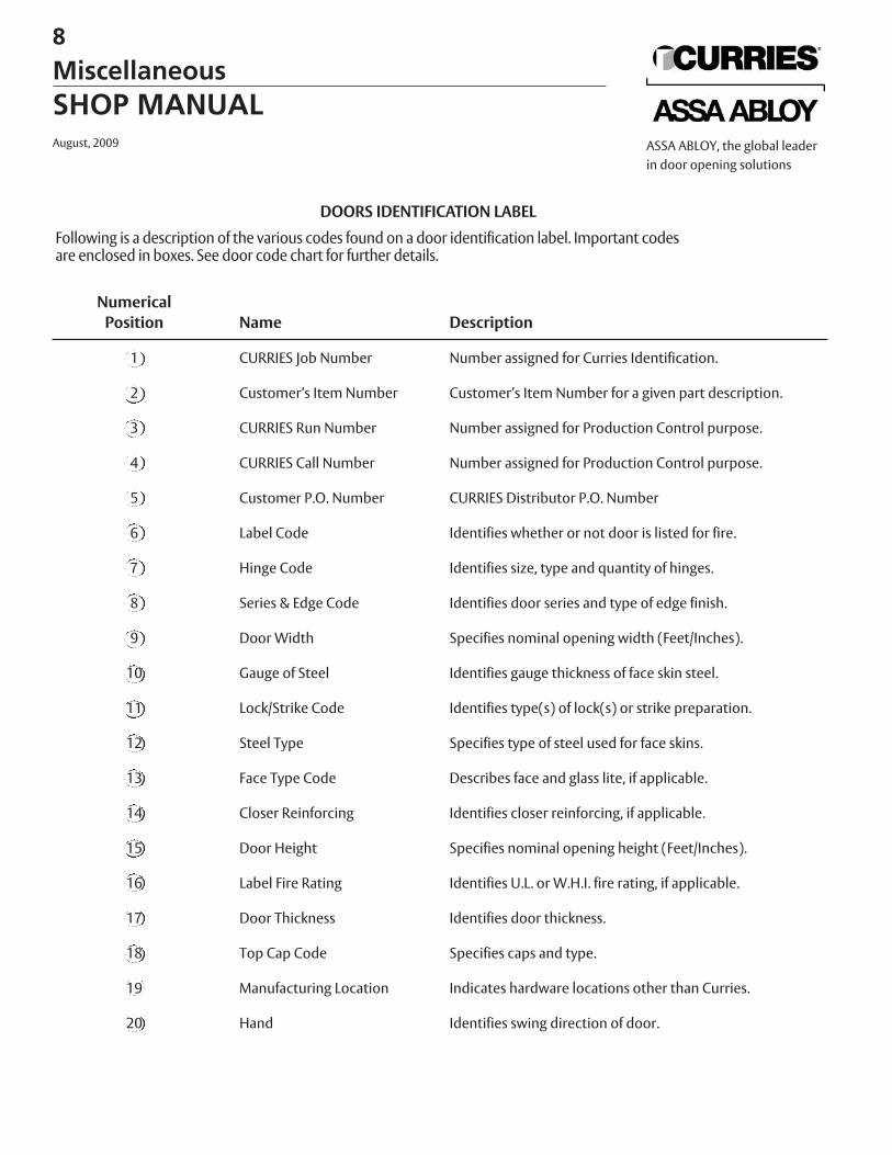
DOORS IDENTIFICATION LABEL
Following is a description of the various codes found on a door identification label. Important codesare enclosed in boxes. See door code chart for further details.
NumericalPosition Name Description
1 CURRIES Job Number Number assigned for Curries Identification.
2 Customer’s Item Number Customer’s Item Number for a given part description.
3 CURRIES Run Number Number assigned for Production Control purpose.
4 CURRIES Call Number Number assigned for Production Control purpose.
5 Customer P.O. Number CURRIES Distributor P.O. Number
6 Label Code Identifies whether or not door is listed for fire.
7 Hinge Code Identifies size, type and quantity of hinges.
8 Series & Edge Code Identifies door series and type of edge finish.
9 Door Width Specifies nominal opening width (Feet/Inches).
10 Gauge of Steel Identifies gauge thickness of face skin steel.
11 Lock/Strike Code Identifies type(s) of lock(s) or strike preparation.
12 Steel Type Specifies type of steel used for face skins.
13 Face Type Code Describes face and glass lite, if applicable.
14 Closer Reinforcing Identifies closer reinforcing, if applicable.
15 Door Height Specifies nominal opening height (Feet/Inches).
16 Label Fire Rating Identifies U.L. or W.H.I. fire rating, if applicable.
17 Door Thickness Identifies door thickness.
18 Top Cap Code Specifies caps and type.
19 Manufacturing Location Indicates hardware locations other than Curries.
20 Hand Identifies swing direction of door.
8
MiscellaneousSHOP MANUALAugust, 2009 ASSA ABLOY, the global leader
in door opening solutions
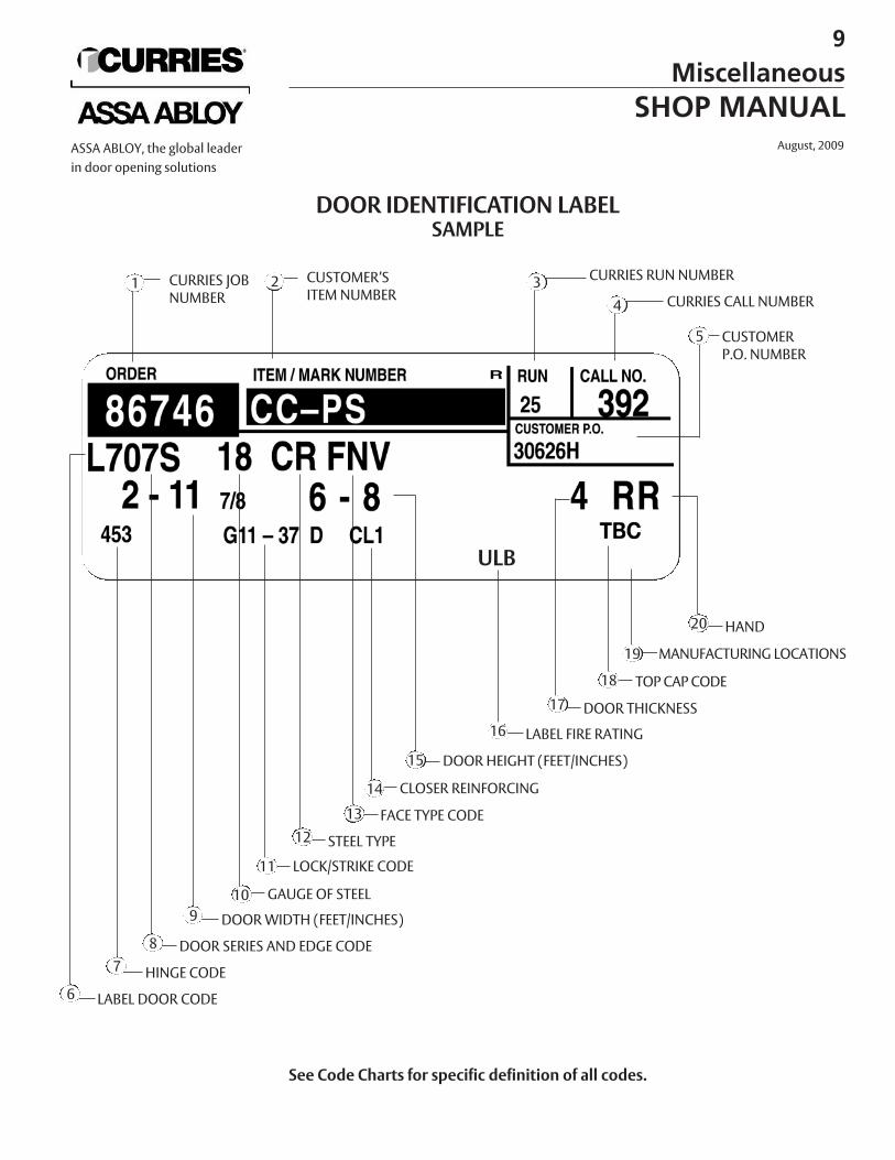
DOOR IDENTIFICATION LABELSAMPLE
CURRIES JOB NUMBER
CUSTOMER’S ITEM NUMBER
CURRIES RUN NUMBER
CURRIES CALL NUMBER
HAND20
LABEL DOOR CODE
See Code Charts for specific definition of all codes.
6
1 2 34
CUSTOMER P.O. NUMBER
5
HINGE CODE7DOOR SERIES AND EDGE CODE8
DOOR WIDTH (FEET/INCHES)9GAUGE OF STEEL10
LOCK/STRIKE CODE11
STEEL TYPE12FACE TYPE CODE13
DOOR HEIGHT (FEET/INCHES)15
CLOSER REINFORCING14
DOOR THICKNESS17TOP CAP CODE18
MANUFACTURING LOCATIONS19
LABEL FIRE RATING16
ULB
9
MiscellaneousSHOP MANUAL
August, 2009ASSA ABLOY, the global leaderin door opening solutions
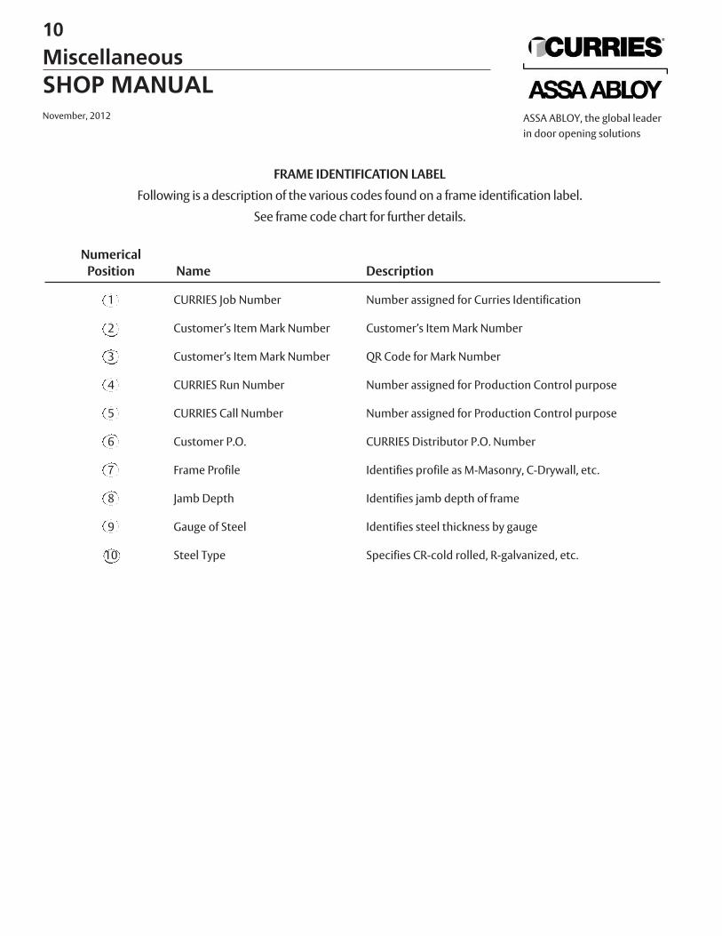
FRAME IDENTIFICATION LABEL
Following is a description of the various codes found on a frame identification label.
See frame code chart for further details.
NumericalPosition Name Description
1 CURRIES Job Number Number assigned for Curries Identification
2 Customer’s Item Mark Number Customer’s Item Mark Number
3 Customer’s Item Mark Number QR Code for Mark Number
4 CURRIES Run Number Number assigned for Production Control purpose
5 CURRIES Call Number Number assigned for Production Control purpose
6 Customer P.O. CURRIES Distributor P.O. Number
7 Frame Profile Identifies profile as M-Masonry, C-Drywall, etc.
8 Jamb Depth Identifies jamb depth of frame
9 Gauge of Steel Identifies steel thickness by gauge
10 Steel Type Specifies CR-cold rolled, R-galvanized, etc.
10
MiscellaneousSHOP MANUALNovember, 2012 ASSA ABLOY, the global leader
in door opening solutions
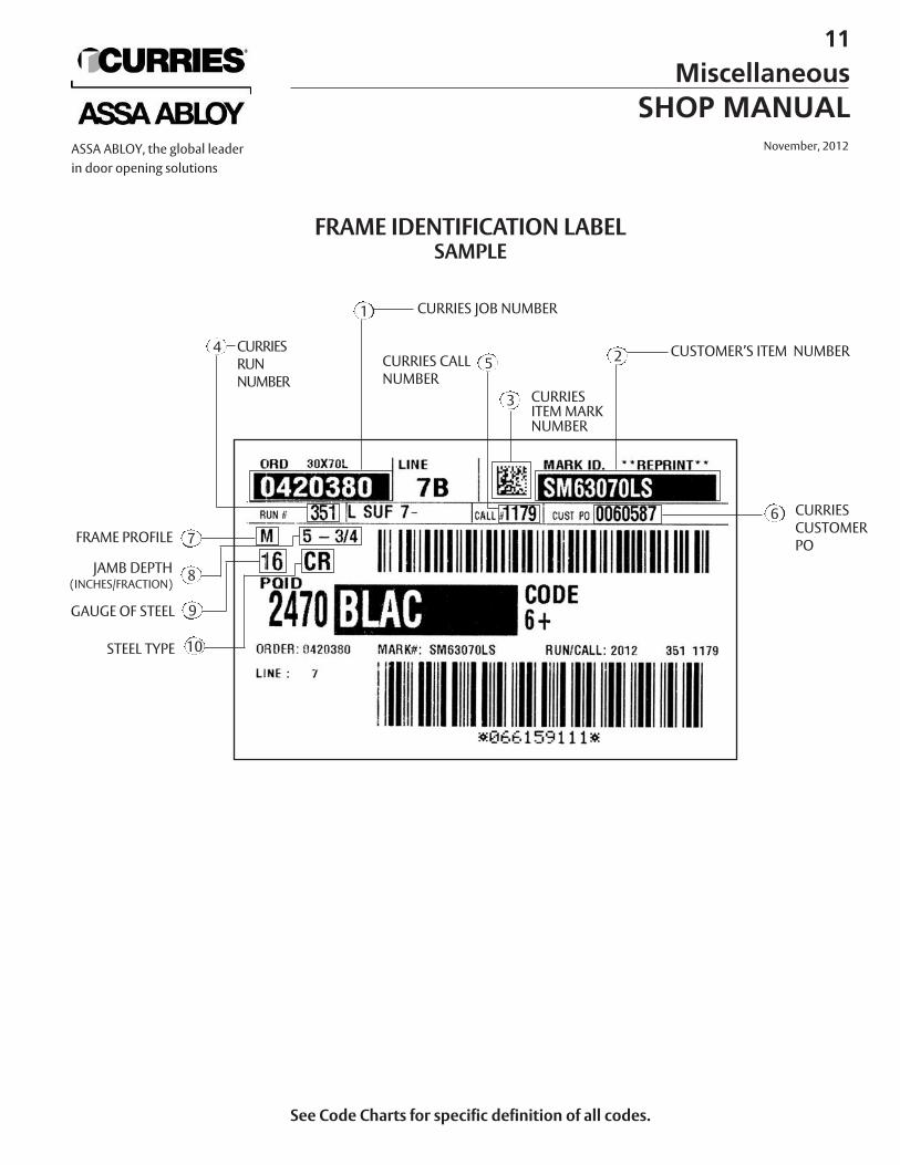
CURRIES CUSTOMERPO
6
FRAME IDENTIFICATION LABELSAMPLE
See Code Charts for specific definition of all codes.
1
2
CURRIES JOB NUMBER
CUSTOMER’S ITEM NUMBER
CURRIES ITEM MARKNUMBER
CURRIES RUNNUMBER
4
STEEL TYPE
GAUGE OF STEEL
FRAME PROFILE
JAMB DEPTH (INCHES/FRACTION)
10
9
8
7
CURRIES CALLNUMBER
5
11
MiscellaneousSHOP MANUAL
November, 2012ASSA ABLOY, the global leaderin door opening solutions
3