Embed Size (px)
Citation preview

CCNA Security
Chapter 2 Lab A: Securing the Router for Administrative Access Instructor Version
Topology
IP Addressing Table
Device Interface IP Address Subnet Mask Default Gateway Switch PortR1 FA0/1 192.168.1.1 255.255.255.0 N/A S1 FA0/5
S0/0/0 (DCE) 10.1.1.1 255.255.255.252 N/A N/AR2 S0/0/0 10.1.1.2 255.255.255.252 N/A N/A
S0/0/1 (DCE) 10.2.2.2 255.255.255.252 N/A N/AR3 FA0/1 192.168.3.1 255.255.255.0 N/A S3 FA0/5
S0/0/1 10.2.2.1 255.255.255.252 N/A N/APC-A NIC 192.168.1.3 255.255.255.0 192.168.1.1 S1 FA0/6PC-C NIC 192.168.3.3 255.255.255.0 192.168.3.1 S3 FA0/18
All contents are Copyright © 1992–2009 Cisco Systems, Inc. All rights reserved. This document is Cisco Public Information. Page 1 of 57

CCNA Security
Objectives
Part 1: Basic Network Device Configuration
Cable the network as shown in the topology.
Configure basic IP addressing for routers and PCs.
Configure static routing, including default routes.
Verify connectivity between hosts and routers.
Part 2: Control Administrative Access for Routers
Configure and encrypt all passwords.
Configure a login warning banner.
Configure enhanced username password security.
Configure enhanced virtual login security.
Configure an SSH server on a router.
Configure an SSH client and verify connectivity.
Part 3: Configure Administrative Roles
Create multiple role views and grant varying privileges.
Verify and contrast views.
Part 4: Configure Cisco IOS Resilience and Management Reporting
Secure the Cisco IOS image and configuration files.
Configure a router as a synchronized time source for other devices using NTP.
Configure Syslog support on a router.
Install a Syslog server on a PC and enable it.
Configure trap reporting on a router using SNMP.
Make changes to the router and monitor syslog results on the PC.
Part 5: Configure Automated Security Features
Lock down a router using AutoSecure and verify the configuration.
Use the SDM Security Audit tool to identify vulnerabilities and lock down services.
Contrast the AutoSecure configuration with SDM.
Background/Scenario
The router is a key component that controls the movement of data into and out of the network and between devices within the network. It is particularly important to protect the network routers because the failure of one of these devices due to malicious activity could make sections of the network or the entire network inaccessible. Controlling access to routers and enabling reporting on routers are critical to network security and should be part of a comprehensive security policy.
All contents are Copyright © 1992–2009 Cisco Systems, Inc. All rights reserved. This document is Cisco Public Information. Page 2 of 57

CCNA Security
In this lab, you build a multi-router network and configure the routers and hosts. You use various CLI and SDM tools to secure local and remote access to the routers, analyze potential vulnerabilities, and take steps to mitigate them. You also enable management reporting to monitor router configuration changes.
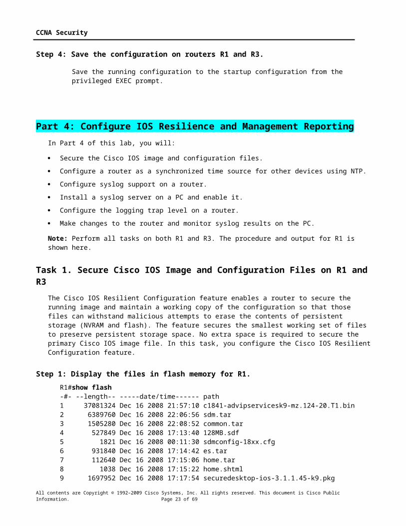
The router commands and output in this lab are from Cisco 1841s using Cisco IOS software, release 12.4(20)T (advanced IP image). Other routers and Cisco IOS versions can be used. See the Router Interface Summary table at the end of the lab to determine which interface identifiers to use based on the equipment in the lab. Depending on the model of the router, the commands available and output produced may vary from what is shown in this lab.
Note: Make sure that the routers and the switches have been erased and have no startup configurations.
Instructor Note: Instructions for erasing switches and routers are provided in the Lab Manual, located on Academy Connection in the Tools section.
Required Resources
3 routers with SDM 2.5 installed (Cisco 1841 with Cisco IOS software, release 12.4(20)T1 or comparable)
2 switches (Cisco 2960 or comparable)
PC-A: Windows XP, Vista, or Windows Server with PuTTy SSH Client (no ACS required for this lab)
PC-C: Windows XP or Vista with PuTTy SSH Client and Kiwi or Tftpd32 Syslog server
Serial and Ethernet cables as shown in the topology
Rollover cables to configure the routers via the console port
Instructor Note:This lab is divided into five parts. Each part can be administered individually or in combination with others as time permits. The main goal is to configure various Cisco IOS and SDM security features on routers R1 and R3. R1 and R3 are on separate networks and communicate through R2, which simulates a connection to an ISP. Students can work in teams of two for router security configuration, one student configuring R1 and the other student configuring R3.
Although switches are shown in the topology, students can omit the switches and use crossover cables between the PCs and routers R1 and R3.
The basic running configs for all three routers are captured after Parts 1 and 2 of the lab are completed. The running config commands that are added in Parts 3 and 4 are captured and listed separately. The running configs generated by AutoSecure for R3 and SDM Security Audit for R1 in Part 5 of the lab are listed separately. All configs are found at the end of the lab.
All contents are Copyright © 1992–2009 Cisco Systems, Inc. All rights reserved. This document is Cisco Public Information. Page 3 of 57

CCNA Security
Part 1: Basic Router ConfigurationIn Part 1 of this lab, you set up the network topology and configure basic settings such as interface IP addresses and static routing.
Step 1: Cable the network.
Attach the devices shown in the topology diagram and cable as necessary.
Step 2: Configure basic settings for each router.
a. Configure host names as shown in the topology.
b. Configure interface IP addresses as shown in the IP Addressing Table.
c. Configure a clock rate for routers with a DCE serial cable attached to their serial interface. Router R1 is shown here as an example.
R1(config)#interface S0/0/0R1(config-if)#clock rate 64000
d. To prevent the router from attempting to translate incorrectly entered commands as though they were host names, disable DNS lookup. Router R1 is shown here as an example.
R1(config)#no ip domain-lookup
Step 3: Configure static routing on the routers.a. Configure a static default route from R1 to R2 and from R3 to R2.
b. Configure a static route from R2 to the R1 LAN and from R2 to the R3 LAN.
Step 4: Configure PC host IP settings.
Configure a static IP address, subnet mask, and default gateway for PC-A and PC-C as shown in the IP Addressing Table.
Step 5: Verify connectivity between PC-A and R3.a. Ping from R1 to R3.
Were the ping results successful? Yes.
If the pings are not successful, troubleshoot the basic device configurations before continuing.
b. Ping from PC-A on the R1 LAN to PC-C on the R3 LAN.
Were the ping results successful? Yes.
If the pings are not successful, troubleshoot the basic device configurations before continuing.
Note: If you can ping from PC-A to PC-C you have demonstrated that static routing is configured and functioning correctly. If you cannot ping but the device interfaces are up and IP addresses are correct, use the show run and show ip route commands to help identify routing protocol related problems.
All contents are Copyright © 1992–2009 Cisco Systems, Inc. All rights reserved. This document is Cisco Public Information. Page 4 of 57

CCNA Security
Step 6: Save the basic running configuration for each router.
Use the Transfer > Capture text option in HyperTerminal or some other method to capture the running configs for each router. Save the three files so that they can be used to restore configs later in the lab.
Part 2: Control Administrative Access for RoutersIn Part 2 of this lab, you will:
Configure and encrypt passwords.
Configure a login warning banner.
Configure enhanced username password security.
Configure enhanced virtual login security.
Configure an SSH server on router R1 using the CLI.
Research terminal emulation client software and configure the SSH client.
Note: Perform all tasks, on both R1 and R3. The procedures and output for R1 are shown here.
Task 1. Configure and Encrypt Passwords on Routers R1 and R3
Step 1: Configure a minimum password length for all router passwords.
Use the security passwords command to set a minimum password length of 10 characters.
R1(config)#security passwords min-length 10
Step 2: Configure the enable secret password.
Configure the enable secret encrypted password on both routers.
R1(config)#enable secret cisco12345
How does configuring an enable secret password help protect a router from being compromised by an attack?
The goal is to always prevent unauthorized users from accessing a device using Telnet, SSH, or via the console. If attackers are able to penetrate this first layer of defense, using an enable secret password prevents them from being able to alter the configuration of the device. Unless the enable secret password is known, a user cannot go into privileged EXEC mode where they can display the running config and enter various configuration commands to make changes to the router. This provides an additional layer of security.
Step 3: Configure basic console, auxiliary port, and virtual access lines.Note: Passwords in this task are set to a minimum of 10 characters but are relatively simple for the benefit of performing the lab. More complex passwords are recommended in a production network.
a. Configure a console password and enable login for routers. For additional security, the exec-timeout command causes the line to log out after 5 minutes of inactivity. The logging synchronous command prevents console messages from interrupting command entry.
All contents are Copyright © 1992–2009 Cisco Systems, Inc. All rights reserved. This document is Cisco Public Information. Page 5 of 57

CCNA Security
Note: To avoid repetitive logins during this lab, the exec-timeout command can be set to 0 0, which prevents it from expiring. However, this is not considered a good security practice.
R1(config)#line console 0R1(config-line)#password ciscoconR1(config-line)#exec-timeout 5 0R1(config-line)#loginR1(config-line)#logging synchronous
When you configured the password for the console line, what message was displayed?
% Password too short - must be at least 10 characters. Password configuration failed
b. Configure a new password of ciscoconpass for the console.
c. Configure a password for the AUX port for router R1.
R1(config)#line aux 0R1(config-line)#password ciscoauxpassR1(config-line)#exec-timeout 5 0R1(config-line)#login
d. Telnet from R2 to R1.
R2>telnet 10.1.1.1
Were you able to login? Why or why not? No. No password has been set on the vty lines.
What messages were displayed?
Trying 10.1.1.1 ... Open
Password required, but none set
[Connection to 10.1.1.1 closed by foreign host]
e. Configure the password on the vty lines for router R1.
R1(config)#line vty 0 4R1(config-line)#password ciscovtypassR1(config-line)#exec-timeout 5 0R1(config-line)#login
f. Telnet from R2 to R1 again. Were you able to login this time? Yes. A password has been set.
g. Enter privileged EXEC mode and issue the show run command. Can you read the enable secret password? Why or why not? No, the enable secret password is encrypted automatically using the MD5 hash algorithm.
Can you read the console, aux, and vty passwords? Why or why not? Yes, they are all in clear text.
h. Repeat the configuration portion of steps 3a through 3g on router R3.
Step 4: Encrypt clear text passwords.
a. Use the service password-encryption command to encrypt the console, aux, and vty passwords.
R1(config)# service password-encryption
All contents are Copyright © 1992–2009 Cisco Systems, Inc. All rights reserved. This document is Cisco Public Information. Page 6 of 57

CCNA Security
b. Issue the show run command. Can you read the console, aux, and vty passwords? Why or why not?
No, the passwords are now encrypted
c. At what level (number) is the enable secret password encrypted? 5
d. At what level (number) are the other passwords encrypted? 7
e. Which level of encryption is harder to crack and why? 5, because the algorithm is stronger than 7.
Task 2. Configure a Login Warning Banner on Routers R1 and R3
Step 1: Configure a warning message to display prior to login.
a. Configure a warning to unauthorized users with a message-of-the-day (MOTD) banner using the banner motd command. When a user connects to one of the routers, the MOTD banner appears before the login prompt. In this example, the dollar sign ($) is used to start and end the message.
R1(config)#banner motd $Unauthorized access strictly prohibited and prosecuted to the full extent of the law$R1(config)#exit
b. Issue the show run command. What does the $ convert to in the output? The $ is converted to ^C when the running-config is displayed.
c. Exit privileged EXEC mode using the disable or exit command and press Enter to get started. Does the MOTD banner look like what you created with the banner motd command? Yes.
Note: If the MOTD banner is not as you wanted it, recreate it using the banner motd command.
Task 3. Configure Enhanced Username Password Security on Routers R1 and R3.
Step 1: Investigate the options for the username command.
In global configuration mode, enter the following command:
R1(config)#username user01 password ?
What options are available?
0 Specifies an UNENCRYPTED password will follow
7 Specifies a HIDDEN password will follow
LINE The UNENCRYPTED (clear text) user password
Step 2: Create a new user account using the username command.
a. Create the user01 account, specifying the password with no encryption.
R1(config)#username user01 password 0 user01pass
b. Use the show run command to display the running configuration and check the password that is enabled.
All contents are Copyright © 1992–2009 Cisco Systems, Inc. All rights reserved. This document is Cisco Public Information. Page 7 of 57
CCNA Security
You still cannot read the password for the new user account. Even though unencrypted (0) was specified because the service password-encryption command is in effect.
Step 3: Create a new user account with a secret password.a. Create a new user account with MD5 hashing to encrypt the password.
R1(config)#username user02 secret user02pass
b. Exit global configuration mode and save your configuration.
c. Display the running configuration. Which hashing method is used for the password?
MD5, because the secret password was configured.
Step 4: Test the new account by logging in to the console.
a. Set the console line to use the locally defined login accounts.
R1(config)#line console 0R1(config-line)#login localR1(config-line)#endR1#exit
b. Exit to the initial router screen which displays: R1 con0 is now available, Press RETURN to get started.
c. Log in using the user01 account and password previously defined.
What is the difference between logging in at the console now and previously?
You are prompted to enter a Username as well as a password.
d. After logging in, issue the show run command. Were you able to issue the command? Why or why not? No, it requires Privileged EXEC level.
e. Enter privileged EXEC mode using the enable command. Were you prompted for a password? Why or why not? Yes, the new users created will still be required to enter the enable secret password to enter privileged EXEC mode.
Step 5: Test the new account by logging in from a Telnet session.
a. From PC-A, establish a Telnet session with R1.
PC-A>telnet 192.168.1.1
Were you prompted for a user account? Why or why not? No, the vty lines were not set to use the locally defined accounts as the line 0 console was.
b. Set the vty lines to use the locally defined login accounts.
R1(config)#line vty 0 4R1(config-line)#login local
c. From PC-A, telnet to R1 again.
PC-A>telnet 192.168.1.1
Were you prompted for a user account? Why or why not? Yes, the vty lines are now set to use the locally defined accounts.
All contents are Copyright © 1992–2009 Cisco Systems, Inc. All rights reserved. This document is Cisco Public Information. Page 8 of 57

CCNA Security
d. Log in as user01 with a password of user01pass.
e. While telnetted to R1, access privileged EXEC mode with the enable command.
What password did you use? The enable secret password, cisco12345
f. For added security, set the AUX port to use the locally defined login accounts.
R1(config)#line aux 0R1(config-line)#login local
g. End the Telnet session with the exit command.
Task 4. Configure Enhanced Virtual Login Security on Routers R1 and R3
Step 1: Configure the router to watch for login attacks.
Use the login block-for command to help prevent brute-force login attempts from a virtual connection, such as Telnet, SSH, or HTTP. This can help slow down dictionary attacks and help protect the router from a possible DoS attack.
a. From the user EXEC or privileged EXEC prompt, issue the show login command to see the current router login attack settings.
R1#show login No login delay has been applied. No Quiet-Mode access list has been configured. Router NOT enabled to watch for login Attacks
b. Use the login block-for command to configure a 60 second login shutdown (quiet mode timer) if two failed login attempts are made within 30 seconds.
R1(config)#login block-for 60 attempts 2 within 30
c. Exit global configuration mode and issue the show login command.
R1#show login
Is the router enabled to watch for login attacks? Yes What is the default login delay? 1 second between successive attempts.
R1#show login A default login delay of 1 second is applied. No Quiet-Mode access list has been configured. Router enabled to watch for login Attacks. If more than 2 login failures occur in 30 seconds or less, logins will be disabled for 60 seconds.
Router presently in Normal-Mode. Current Watch Window Time remaining: 29 seconds. Login failures for current window: 0. Total login failures: 0.
Step 2: Configure the router to log login activity.
a. Configure the router to generate system logging messages for both successful and failed login attempts. The following commands log every successful login and log failed login attempts after every second failed login.
All contents are Copyright © 1992–2009 Cisco Systems, Inc. All rights reserved. This document is Cisco Public Information. Page 9 of 57

CCNA Security
R1(config)#login on-success logR1(config)#login on-failure log every 2R1(config)#exit
b. Issue the show login command. What additional information is displayed?
All successful logins are logged.
Every 2 failed logins are logged
Step 3: Test the enhanced login security login configuration.
a. From PC-A, establish a Telnet session with R1.
PC-A> telnet 10.1.1.1
b. Attempt to log in with the wrong user ID or password two times. What message was displayed on PC-A after the second failed attempt? Connection to host lost
What message was displayed on the router R1 console after the second failed login attempt?
*Dec 14 22:45:22.851: %SEC_LOGIN-4-LOGIN_FAILED: Login failed [user: x] [Source: 192.168.1.3] [localport: 23] [Reason: Login Authentication Failed - BadUser] at 22:45:22 UTC Sun Dec 14 2008
c. From PC-A, attempt to establish another Telnet session to R1 within 60 seconds. What message was displayed on PC-A after the attempted Telnet connection?
Connecting To 10.1.1.1...Could not open connection to the host, on port 23: Connect failed
What message was displayed on router R1 after the attempted Telnet connection?
*Dec 14 22:24:48.171: %SEC-6-IPACCESSLOGP: list sl_def_acl denied tcp 192.168.1.3(1068) -> 0.0.0.0(23), 1 packet
d. Issue the show login command within 60 seconds. What additional information is displayed? Quiet-Mode status. Router is currently denying logins from all sources.
R1#show login A default login delay of 1 seconds is applied. No Quiet-Mode access list has been configured.
Router enabled to watch for login Attacks. If more than 2 login failures occur in 30 seconds or less, logins will be disabled for 60 seconds.
Router presently in Quiet-Mode. Will remain in Quiet-Mode for 34 seconds. Denying logins from all sources.
All contents are Copyright © 1992–2009 Cisco Systems, Inc. All rights reserved. This document is Cisco Public Information. Page 10 of 57

CCNA Security
Task 5. Configure the SSH Server on Router R1 and R3 Using the CLIIn this task, you use the CLI to configure the router to be managed securely using SSH instead of Telnet. Secure Shell (SSH) is a network protocol that establishes a secure terminal emulation connection to a router or other networking device. SSH encrypts all information that passes over the network link and provides authentication of the remote computer. SSH is rapidly replacing Telnet as the remote login tool of choice for network professionals.
Note: For a router to support SSH, it must be configured with local authentication, (AAA services, or username) or password authentication. In this task, you configure an SSH username and local authentication.
Step 1: Configure a domain name.
Enter global configuration mode and set the domain name.
R1#conf t R1(config)#ip domain-name ccnasecurity.com
Step 2: Configure a privileged user for login from the SSH client.
a. Use the username command to create the user ID with the highest possible privilege level and a secret password.
R1(config)#username admin privilege 15 secret cisco12345
b. Exit to the initial router login screen, and log in with this username. What was the router prompt after you entered the password? The privileged EXEC (enable) prompt # sign. With a privilege level of 15, the login defaults to privileged EXEC mode.
Step 3: Configure the incoming vty lines.
Specify a privilege level of 15 so that a user with the highest privilege level (15) will default to privileged EXEC mode when accessing the vty lines. Other users will default to user EXEC mode. Use the local user accounts for mandatory login and validation, and accept only SSH connections.
R1(config)#line vty 0 4R1(config-line)#privilege level 15 R1(config-line)#login local R1(config-line)#transport input sshR1(config-line)#exit
Note: The login local command should already be configured in a previous step. It is included here to provide all commands if you were doing this for the first time.
Note: If you add the keyword telnet to the transport input command, users can log in using Telnet as well as SSH, however, the router will be less secure. If only SSH is specified, the connecting host must have an SSH client installed.
Step 4: Erase existing key pairs on the router.R1(config)#crypto key zeroize rsa
Note: If no keys exist, you might receive this message: % No Signature RSA Keys found in configuration.
All contents are Copyright © 1992–2009 Cisco Systems, Inc. All rights reserved. This document is Cisco Public Information. Page 11 of 57

CCNA Security
Step 5: Generate the RSA encryption key pair for the router.
The router uses the RSA key pair for authentication and encryption of transmitted SSH data.
Configure the RSA keys with 1024 for the number of modulus bits. The default is 512, and the range is from 360 to 2048.
R1(config)#crypto key generate rsa general-keys modulus 1024 R1(config)#exit
% The key modulus size is 1024 bits% Generating 1024 bit RSA keys, keys will be non-exportable...[OK]R1(config)#*Dec 16 21:24:16.175: %SSH-5-ENABLED: SSH 1.99 has been enabled
Note: The details of encryption methods are covered in Chapter 7.
Step 6: Verify the SSH configuration.
a. Use the show ip ssh command to see the current settings.
R1#show ip ssh
b. Fill in the following information based on the output of the show ip ssh command.
SSH version enabled: Most likely 1.5 to 1.99 Authentication timeout: Default is 120 seconds Authentication retries: Default is 3 tries
Step 7: Configure SSH timeouts and authentication parameters.
The default SSH timeouts and authentication parameters can be altered to be more restrictive using the following commands.
R1(config)#ip ssh time-out 90R1(config)#ip ssh authentication-retries 2
Step 8: Save the running-config to the startup-config.R1#copy running-config startup-config
Task 6. Research Terminal Emulation Client Software and Configure the SSH Client
Step 1: Research terminal emulation client software.
Conduct a web search for freeware terminal emulation client software, such as TeraTerm or PuTTy. What are some capabilities of each?
TeraTerm: This Telnet client provides VT100 emulation, selected VT200/300 emulation, TEK4010 emulation and Kermit, XMODEM, ZMODEM, B-PLUS, and Quick-VAN file transfer protocols. It also offers the ability to connect to SSH2 hosts, a built-in Web server for HTTP pass-through commands, and macro language abilities, including ODBC support, recurring commands, and directory-independent operation.
PuTTy: This application uses both SSH and regular Telnet connections. It runs as an executable application without needing to be installed onto your system.
All contents are Copyright © 1992–2009 Cisco Systems, Inc. All rights reserved. This document is Cisco Public Information. Page 12 of 57

CCNA Security
Step 2: Install an SSH client on PC-A and PC-C.
a. If the SSH client is not already installed, download either TeraTerm or PuTTY.
b. Save the application to the desktop.
Note: The procedure described here is for PuTTY and pertains to PC-A.
Step 3: Verify SSH connectivity to R1 from PC-A.
a. Launch PuTTY by double-clicking the putty.exe icon.
b. Input the R1 Fa0/1 IP address 192.168.1.1 in the Host Name or IP address field.
c. Verify that the SSH radio button is selected.
d. Click Open.
e. In the PuTTY Security Alert window, click Yes.
f. Enter the admin username and password cisco12345 in the PuTTY window.
All contents are Copyright © 1992–2009 Cisco Systems, Inc. All rights reserved. This document is Cisco Public Information. Page 13 of 57

CCNA Security
g. At the R1 privileged EXEC prompt, enter the show users command.
R1#show users
What users are connected to router R1 at this time?
You should see at least two users, one for your console connection and another for the SSH interface.
Line User Host(s) Idle Location 0 con 0 idle 00:00:00* 194 vty 0 admin idle 00:00:33 192.168.1.3
h. Close the PuTTY SSH session window.
i. Try to open a Telnet session to your router from PC-A. Were you able to open the Telnet session? Why or why not?
No, the Telnet session fails because only SSH is enabled for the vty lines.
j. Open a PuTTY SSH session to the router from PC-A. Enter the user01 username and password user01pass in the PuTTY window to try connecting for user who does not have privilege level of 15. Were you able to login? Yes What was the prompt? Because user01 was not created with a privilege level of 15 (the default is level 1), the prompt is user EXEC (>).
k. Use the enable command to enter privilege EXEC mode and enter the enable secret password cisco12345.
l. Disable the generation of system logging messages for successful login attempts.
R1(config)#no login on-success log
Step 4: Save the configuration.
Save the running configuration to the startup configuration from the privileged EXEC prompt.
R1#copy running-config startup-config
Part 3: Configure Administrative RolesIn Part 3 of this lab, you will:
Create multiple administrative roles or views on routers R1 and R3.
Grant each view varying privileges.
Verify and contrast the views.
All contents are Copyright © 1992–2009 Cisco Systems, Inc. All rights reserved. This document is Cisco Public Information. Page 14 of 57

CCNA Security
The role-based CLI access feature allows the network administrator to define views, which are a set of operational commands and configuration capabilities that provide selective or partial access to Cisco IOS EXEC and configuration (config) mode commands. Views restrict user access to the Cisco IOS CLI and configuration information. A view can define which commands are accepted and what configuration information is visible.
Note: Perform all tasks on both R1 and R3. The procedures and output for R1 are shown here.
Task 1. Enable Root View on R1 and R3If an administrator wants to configure another view to the system, the system must be in root view. When a system is in root view, the user has the same access privileges as a user who has level-15 privileges, but the root view user can also configure a new view and add or remove commands from the view. When you are in a CLI view, you have access only to the commands that have been added to that view by the root view user.
Step 1: Enable AAA on router R1.
To define views, AAA must be enabled.
R1#config tR1(config)#aaa new-modelR1(config)#exit
Note: AAA is covered in Chapter 3.
Step 2: Enable the root view.
Use the command enable view to enable the root view. Use the enable secret password cisco12345. If the router does not have an enable secret password, create one now.
R1# enable viewPassword: cisco12345*Dec 16 22:41:17.483: %PARSER-6-VIEW_SWITCH: successfully set to view 'root'.
Task 2. Create New Views for the Admin1, Admin2, and Tech Roles on R1 and R3
Step 1: Create the admin1 view, establish a password, and assign privileges.
a. The admin1 user is the top-level user below root that is allowed to access this router. It has the most authority. The admin1 user can use all show, config, and debug commands. Use the following command to create the admin1 view while in the root view.
R1(config)#parser view admin1R1(config-view)#*Dec 16 22:45:27.587: %PARSER-6-VIEW_CREATED: view 'admin1’ successfully created.<ENTER>
Note: To delete a view, use the command no parser view viewname.
b. Associate the admin1 view with an encrypted password.
R1(config-view)#secret admin1passR1(config-view)#
All contents are Copyright © 1992–2009 Cisco Systems, Inc. All rights reserved. This document is Cisco Public Information. Page 15 of 57

CCNA Security
c. Review the commands that can be configured in the admin1 view. Use the commands ? command. The following is a partial listing of the available commands.
R1(config-view)#commands ? RITE-profile Router IP traffic export profile command mode RMI Node Config Resource Policy Node Config mode RMI Resource Group Resource Group Config mode RMI Resource Manager Resource Manager Config mode RMI Resource Policy Resource Policy Config mode SASL-profile SASL profile configuration mode aaa-attr-list AAA attribute list config mode aaa-user AAA user definition accept-dialin VPDN group accept dialin configuration mode accept-dialout VPDN group accept dialout configuration mode address-family Address Family configuration mode<output omitted>
d. Add all config, show, and debug commands to the admin1 view and then exit from view configuration mode.
R1(config-view)#commands exec include all showR1(config-view)#commands exec include all config terminalR1(config-view)#commands exec include all debugR1(config-view)#end
e. Verify the admin1 view.
R1#enable view admin1Password:admin1pass*Dec 16 22:56:46.971: %PARSER-6-VIEW_SWITCH: successfully set to view 'admin1'
R1#show parser viewR1#Current view is ‘admin1’
f. Examine the commands available in the admin1 view.
R1#?Exec commands: configure Enter configuration mode debug Debugging functions (see also 'undebug') enable Turn on privileged commands exit Exit from the EXEC show Show running system information
g. Examine the show commands available in the admin1 view.
R1#show ? aaa Show AAA values accounting Accounting data for active sessions adjacency Adjacent nodes alignment Show alignment information appfw Application Firewall information archive Archive of the running configuration information arp ARP table<output omitted>
Step 2: Create the admin2 view, establish a password, and assign privileges.
The Admin2 user is a junior administrator in training who is allowed to view all configurations but is not allowed to configure the routers or use debug commands.
All contents are Copyright © 1992–2009 Cisco Systems, Inc. All rights reserved. This document is Cisco Public Information. Page 16 of 57

CCNA Security
a. Use the enable view command to enable the root view, and enter the enable secret password cisco12345.
R1#enable viewPassword:cisco12345
b. Use the following command to create the admin2 view.
R1(config)#parser view admin2R1(config-view)#*Dec 16 23:02:27.587: %PARSER-6-VIEW_CREATED: view 'admin2’ successfully created. <ENTER>
c. Associate the admin2 view with a password.
R1(config-view)#secret admin2passR1(config-view)#
d. Add all show commands to the view and then exit from view configuration mode.
R1(config-view)#commands exec include all showR1(config-view)#end
e. Verify the admin2 view.
R1(config-view)#endR1#enable view admin2Password: admin2pass*Dec 16 23:05:46.971: %PARSER-6-VIEW_SWITCH: successfully set to view 'admin2'R1#show parser viewR1# Current view is ‘admin2’
f. Examine the commands available in the admin2 view.
R1#?Exec commands: enable Turn on privileged commands exit Exit from the EXEC show Show running system information
What is missing from the list of admin2 commands that is present in the admin1 commands? Configure and debug
Step 3: Create the tech view, establish a password, and assign privileges.
a. The Tech user typically installs end-user devices and cabling. Tech users are only allowed to use selected show commands.
b. Use the enable view command to enable the root view, and enter the enable secret password cisco12345.
R1#enable viewPassword:cisco12345
c. Use the following command to create the tech view.
R1(config)#parser view tech R1(config-view)#
*Dec 16 23:10:27.587: %PARSER-6-VIEW_CREATED: view 'tech’ successfully created. <ENTER>
d. Associate the tech view with a password.
All contents are Copyright © 1992–2009 Cisco Systems, Inc. All rights reserved. This document is Cisco Public Information. Page 17 of 57

CCNA Security
R1(config-view)#secret techpasswdR1(config-view)#
e. Add the following show commands to the view and then exit from view configuration mode.
R1(config-view)#commands exec include show versionR1(config-view)#commands exec include show interfacesR1(config-view)#commands exec include show ip interface briefR1(config-view)#commands exec include show parser viewR1(config-view)#end
f. Verify the tech view.
R1#enable view techPassword:techpasswd*Dec 16 23:13:46.971: %PARSER-6-VIEW_SWITCH: successfully set to view 'tech'R1#show parser viewR1#Current view is ‘tech’
g. Examine the commands available in the tech view.
R1#?Exec commands: enable Turn on privileged commands exit Exit from the EXEC show Show running system information
h. Examine the show commands available in the tech view.
R1#show ? flash: display information about flash: file system interfaces Interface status and configuration ip IP information parser Show parser commands version System hardware and software status
i. Issue the show ip interface brief command. Were you able to do it as the tech user? Why or why not? Yes, it is one of the allowed commands.
j. Issue the show ip route command. Were you able to do it as the tech user? No, it is not one of the allowed commands.
R1#show ip route ^% Invalid input detected at '^' marker.
k. Return to root view with the enable view command.
R1# enable viewPassword: cisco12345
l. Issue the show run command to see the views you created. For tech view, why are the show and show ip commands listed as well as show ip interface and show ip interface brief? All parts of the command must be listed for the more specific parameters to work.
Step 4: Save the configuration on routers R1 and R3.
Save the running configuration to the startup configuration from the privileged EXEC prompt.
All contents are Copyright © 1992–2009 Cisco Systems, Inc. All rights reserved. This document is Cisco Public Information. Page 18 of 57

CCNA Security
Part 4: Configure IOS Resilience and Management Reporting In Part 4 of this lab, you will:
Secure the Cisco IOS image and configuration files.
Configure a router as a synchronized time source for other devices using NTP.
Configure syslog support on a router.
Install a syslog server on a PC and enable it.
Configure the logging trap level on a router.
Make changes to the router and monitor syslog results on the PC.
Note: Perform all tasks on both R1 and R3. The procedure and output for R1 is shown here.
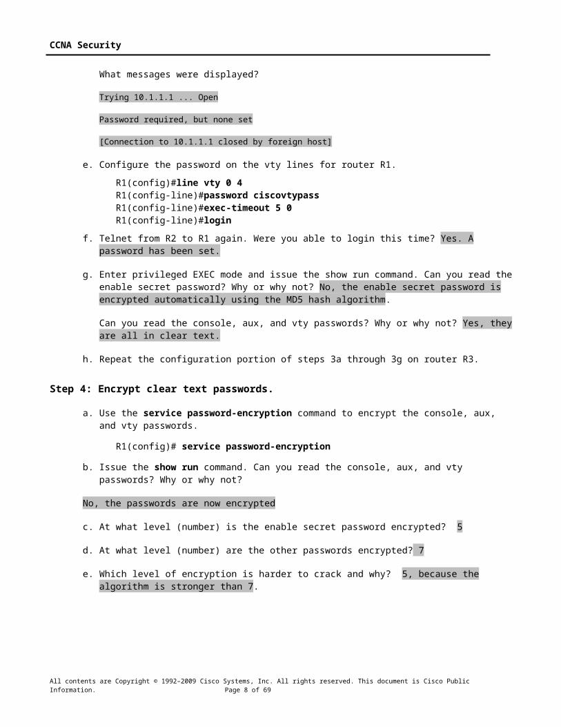
Task 1. Secure Cisco IOS Image and Configuration Files on R1 and R3The Cisco IOS Resilient Configuration feature enables a router to secure the running image and maintain a working copy of the configuration so that those files can withstand malicious attempts to erase the contents of persistent storage (NVRAM and flash). The feature secures the smallest working set of files to preserve persistent storage space. No extra space is required to secure the primary Cisco IOS image file. In this task, you configure the Cisco IOS Resilient Configuration feature.
Step 1: Display the files in flash memory for R1.R1#show flash-#- --length-- -----date/time------ path1 37081324 Dec 16 2008 21:57:10 c1841-advipservicesk9-mz.124-20.T1.bin2 6389760 Dec 16 2008 22:06:56 sdm.tar3 1505280 Dec 16 2008 22:08:52 common.tar4 527849 Dec 16 2008 17:13:40 128MB.sdf5 1821 Dec 16 2008 00:11:30 sdmconfig-18xx.cfg6 931840 Dec 16 2008 17:14:42 es.tar7 112640 Dec 16 2008 17:15:06 home.tar8 1038 Dec 16 2008 17:15:22 home.shtml9 1697952 Dec 16 2008 17:17:54 securedesktop-ios-3.1.1.45-k9.pkg10 415956 Dec 16 2008 17:21:16 sslclient-win-1.1.4.176.pkg
14815232 bytes available (49197056 bytes used)
Step 2: Secure the Cisco IOS image and archive a copy of the running configuration.
a. The secure boot-image command enables Cisco IOS image resilience, which hides the file from dir and show commands. The file cannot be viewed, copied, modified, or removed using EXEC mode commands. (It can be viewed in ROMMON mode.) When turned on for the first time, the running image is secured.
R1(config)#secure boot-image.Dec 17 25:40:13.170: %IOS_RESILIENCE-5-IMAGE_RESIL_ACTIVE: Successfully secured running image
b. The secure boot-config command takes a snapshot of the router running configuration and securely archives it in persistent storage (flash).
All contents are Copyright © 1992–2009 Cisco Systems, Inc. All rights reserved. This document is Cisco Public Information. Page 19 of 57

CCNA Security
R1(config)#secure boot-config.Dec 17 25:42:18.691: %IOS_RESILIENCE-5-CONFIG_RESIL_ACTIVE: Successfully secured config archive [flash:.runcfg-20081219-224218.ar]
Step 3: Verify that your image and configuration are secured.
a. You can use only the show secure bootset command to display the archived filename. Display the status of configuration resilience and the primary bootset filename.
R1#show secure bootsetIOS resilience router id FTX1111W0QF
IOS image resilience version 12.4 activated at 25:40:13 UTC Wed Dec 17 2008Secure archive flash:c1841-advipservicesk9-mz.124-20.T1.bin type is image (elf)[] file size is 37081324 bytes, run size is 37247008 bytes Runnable image, entry point 0x8000F000, run from ram
IOS configuration resilience version 12.4 activated at 25:42:18 UTC Wed Dec 17 2008Secure archive flash:.runcfg-20081219-224218.ar type is configconfiguration archive size 1986 bytes
b. What is the name of the archived running config file and on what is the name based? runcfg-20081217-254218.ar. It is based on the date and time archived by the secure boot-config command.
Step 4: Display the files in flash memory for R1.
a. Display the contents of flash using the show flash command.
R1#show flash-#- --length-- -----date/time------ path1 6389760 Dec 16 2008 22:06:56 sdm.tar2 1505280 Dec 16 2008 22:08:52 common.tar3 527849 Dec 16 2008 17:13:40 128MB.sdf4 1821 Dec 16 2008 00:11:30 sdmconfig-18xx.cfg5 512000 Dec 16 2008 17:14:24 dg_sdm.tar6 931840 Dec 16 2008 17:14:42 es.tar7 112640 Dec 16 2008 17:15:06 home.tar8 1038 Dec 16 2008 17:15:22 home.shtml10 1697952 Dec 16 2008 17:17:54 securedesktop-ios-3.1.1.45-k9.pkg11 415956 Dec 16 2008 17:21:16 sslclient-win-1.1.4.176.pkg
14807040 bytes available (49205248 bytes used)
b. Is the Cisco IOS image or the archived running config file listed? No, they are hidden.
c. How can you tell that the Cisco IOS image is still there? The bytes available and bytes used are approximately the same as before (minus the space taken by the archived running config file).
Step 5: Disable the IOS Resilient Configuration feature.
a. Disable the Resilient Configuration feature for the Cisco IOS image.
R1#config t
All contents are Copyright © 1992–2009 Cisco Systems, Inc. All rights reserved. This document is Cisco Public Information. Page 20 of 57

CCNA Security
R1(config)#no secure boot-image.Dec 17 25:48:23.009: %IOS_RESILIENCE-5-IMAGE_RESIL_INACTIVE: Disabled secure image archival
b. Disable the Resilient Configuration feature for the running config file.
R1(config)#no secure boot-config.Dec 17 25:48:47.972: %IOS_RESILIENCE-5-CONFIG_RESIL_INACTIVE: Disabled secure config archival [removed flash:.runcfg-20081219-224218.ar]
Step 6: Verify that the Cisco IOS image is now visible in flash.R1#show flash-#- --length-- -----date/time------ path1 37081324 Dec 16 2008 21:57:10 c1841-advipservicesk9-mz.124-20.T1.bin2 6389760 Dec 16 2008 22:06:56 sdm.tar3 1505280 Dec 16 2008 22:08:52 common.tar4 527849 Dec 16 2008 17:13:40 128MB.sdf5 1821 Dec 16 2008 00:11:30 sdmconfig-18xx.cfg6 931840 Dec 16 2008 17:14:42 es.tar7 112640 Dec 16 2008 17:15:06 home.tar8 1038 Dec 16 2008 17:15:22 home.shtml9 1697952 Dec 16 2008 17:17:54 securedesktop-ios-3.1.1.45-k9.pkg10 415956 Dec 16 2008 17:21:16 sslclient-win-1.1.4.176.pkg
14815232 bytes available (49197056 bytes used)
Step 7: Save the configuration on both routers.
Save the running configuration to the startup configuration from the privileged EXEC prompt.
Task 2. Configure a Synchronized Time Source Using NTPRouter R2 will be the master NTP clock source for routers R1 and R3.
Note: R2 could also be the master clock source for switches S1 and S3, but it is not necessary to configure them for this lab.
Step 1: Set Up the NTP Master using Cisco IOS commands.
R2 is the master NTP server in this lab. All other routers and switches learn their time from it, either directly or indirectly. For this reason, you must first ensure that R2 has the correct Coordinated Universal Time set.
Note: If you are using SDM to configure R2 to support NTP, skip this step and go to Step 2.
a. Display the current time set on the router using the show clock command.
R2#show clock*01:19:02.331 UTC Mon Dec 15 2008
b. To set the time on the router, use the clock set time command.
R2#clock set 20:12:00 Dec 17 2008R2#*Dec 17 20:12:18.000: %SYS-6-CLOCKUPDATE: System clock has been updated from 01:20:26 UTC Mon Dec 15 2008 to 20:12:00 UTC Wed Dec 17 2008, configured from console by admin on console.
All contents are Copyright © 1992–2009 Cisco Systems, Inc. All rights reserved. This document is Cisco Public Information. Page 21 of 57

CCNA Security
c. Configure R2 as the NTP master using the ntp master stratum-number command in global configuration mode. The stratum number indicates the distance from the original source. For this lab, use a stratum number of 3 on R2. When a device learns the time from an NTP source, its stratum number becomes one greater than the stratum number of its source.
R2(config)#ntp master 3
Step 2: Configure R1 and R3 as NTP clients using the CLI.
a. R1 and R3 will become NTP clients of R2. To configure R1, use the global configuration command ntp server hostname. The host name can also be an IP address. The command ntp update-calendar periodically updates the calendar with the NTP time.
R1(config)#ntp server 10.1.1.2R1(config)#ntp update-calendar
b. Verify that R1 has made an association with R2 with the show ntp associations command. You can also use the more verbose version of the command by adding the detail argument. It might take some time for the NTP association to form.
R1#show ntp associations
address ref clock st when poll reach delay offset disp~10.1.1.2 127.127.1.1 3 14 64 3 0.000 -280073 3939.7*sys.peer, #selected, +candidate, -outlyer, x falseticker, ~ configured
c. Issue the debug ntp all command to see NTP activity on R1 as it synchronizes with R2.
R1#debug ntp allNTP events debugging is onNTP core messages debugging is onNTP clock adjustments debugging is onNTP reference clocks debugging is onNTP packets debugging is on
Dec 17 20.12:18.554: NTP message sent to 10.1.1.2, from interface 'Serial0/0/0' (10.1.1.1).Dec 17 20.12:18.574: NTP message received from 10.1.1.2 on interface 'Serial0/0/0' (10.1.1.1).Dec 17 20:12:18.574: NTP Core(DEBUG): ntp_receive: message receivedDec 17 20:12:18.574: NTP Core(DEBUG): ntp_receive: peer is 0x645A3120, next action is 1.Dec 17 20:12:18.574: NTP Core(DEBUG): receive: packet given to process_packetDec 17 20:12:18.578: NTP Core(INFO): system event 'event_peer/strat_chg' (0x04)status 'sync_alarm, sync_ntp, 5 events, event_clock_reset' (0xC655)Dec 17 20:12:18.578: NTP Core(INFO): synchronized to 10.1.1.2, stratum 3Dec 17 20:12:18.578: NTP Core(INFO): system event 'event_sync_chg' (0x03) status 'leap_none, sync_ntp, 6 events, event_peer/strat_chg' (0x664)Dec 17 20:12:18.578: NTP Core(NOTICE): Clock is synchronized.Dec 17 20:12:18.578: NTP Core(INFO): system event 'event_peer/strat_chg' (0x04)status 'leap_none, sync_ntp, 7 events, event_sync_chg' (0x673)Dec 17 20:12:23.554: NTP: Calendar updated.
d. Issue the undebug all or the no debug ntp all command to turn off debugging.
R1#undebug all
All contents are Copyright © 1992–2009 Cisco Systems, Inc. All rights reserved. This document is Cisco Public Information. Page 22 of 57
CCNA Security
e. Verify the time on R1 after it has made an association with R2.
R1#show clock*20:12:24.859 UTC Wed Dec 17 2008
Step 3: (Optional) Configure R1 and R3 as NTP clients using SDM.
You can also use SDM to configure the router to support NTP. If you configured R1 as an NTP client using Cisco IOS commands in Step 2, you can skip this step, but read through it to become familiar with the process. If you configured R1 and R3 as NTP clients using Cisco IOS commands in Step 2 you can still perform this step but you need to issue the following commands first on each router.
R1(config)#no ntp server 10.1.1.2R1(config)#no ntp update-calendar
a. From the CLI, enable the http server on R1.
R1(config)#ip http server
b. Open a browser window on PC-A and start SDM by entering the R1 IP address 192.168.1.1 in the address field. Log in as admin with password cisco12345.
c. To configure SDM to allow you to preview the commands before sending them to the router, select Edit > Preferences.
d. In the User Preferences window, select Preview commands before delivering to router and click OK.
e. To configure an NTP server, click the Configure button and select Additional Tasks > Router Properties > NTP/SNTP. Click Add.
All contents are Copyright © 1992–2009 Cisco Systems, Inc. All rights reserved. This document is Cisco Public Information. Page 23 of 57

CCNA Security
f. In the NTP Server IP Address field, enter the IP address of the R2 master NTP router (10.1.1.2) and click OK.
g. In the Deliver Configuration to Router window, make sure that the Save running config to router’s startup config check box is checked and click Deliver.
h. Click OK in the Commands Delivery Status window.
i. Open a console connection to the router, and verify the associations and time on R1 after it has made an association with R2. It might take some time for the NTP association to form.
R1#show ntp associations
address ref clock st when poll reach delay offset disp~10.1.1.2 127.127.1.1 3 14 64 3 0.000 -280073 3939.7*sys.peer, #selected, +candidate, -outlyer, x falseticker, ~ configured
R1#show clock*20:12:24.859 UTC Wed Dec 17 2008
All contents are Copyright © 1992–2009 Cisco Systems, Inc. All rights reserved. This document is Cisco Public Information. Page 24 of 57

CCNA Security
Task 3. Configure syslog Support on R1 and PC-A
Step 1: Install the syslog server.
The Kiwi Syslog Daemon is a dedicated syslog server. Another application is Tftpd32, which includes a TFTP server, TFTP client, and a syslog server and viewer. You can use either with this lab. Both are available as a free version and run with Microsoft Windows.
If a syslog server is not currently installed on the host, download the latest version of Kiwi from http://www.kiwisyslog.com or Tftpd32 from http://tftpd32.jounin.net and install it on your desktop. If it is already installed, go to Step 2.
Note: This lab uses the Kiwi syslog server.
Step 2: Configure R1 to log messages to the syslog server using the CLI.
a. Verify that you have connectivity between R1 and the host by pinging the R1 Fa0/1 interface IP address 192.168.1.1. If it is not successful, troubleshoot as necessary before continuing.
b. NTP was configured in Task 2 to synchronize the time on the network. Displaying the correct time and date in syslog messages is vital when using syslog to monitor a network. If the correct time and date of a message is not known, it can be difficult to determine what network event caused the message.
Verify that the timestamp service for logging is enabled on the router using the show run command. Use the following command if the timestamp service is not enabled.
R1(config)#service timestamps log datetime msec
c. Configure the syslog service on the router to send syslog messages to the syslog server.
R1(config)#logging 192.168.1.3
Step 3: Configure the logging severity level on R1.
Logging traps can be set to support the logging function. A trap is a threshold that when reached triggers a log message. The level of logging messages can be adjusted to allow the administrator to determine what kinds of messages are sent to the syslog server. Routers support different levels of logging. The eight levels range from 0 (emergencies), indicating that the system is unstable, to 7 (debugging), which sends messages that include router information.
Note: The default level for syslog is 6, informational logging. The default for console and monitor logging is 7, debugging.
a. Use the logging trap command to determine the options for the command and the various trap levels available.
R1(config)#logging trap ?<0-7> Logging severity levelalerts Immediate action needed (severity=1)critical Critical conditions (severity=2)debugging Debugging messages (severity=7)emergencies System is unusable (severity=0)errors Error conditions (severity=3)informational Informational messages (severity=6)notifications Normal but significant conditions (severity=5)warnings Warning conditions (severity=4)
All contents are Copyright © 1992–2009 Cisco Systems, Inc. All rights reserved. This document is Cisco Public Information. Page 25 of 57

CCNA Security
<cr>
b. Define the level of severity for messages sent to the syslog server. To configure the severity levels, use either the keyword or the severity level number (0–7).
Severity Level Keyword DescriptionSeverity level Keyword Meaning0 emergencies System unusable1 alerts Immediate action required2 critical Critical conditions3 errors Error conditions4 warnings Warning conditions5 notifications Normal but significant condition6 informational Informational messages7 debugging Debugging messages
Note: The severity level includes the level specified and anything with a lower severity number. If you set the level to 4 or use the keyword warnings, you capture messages with severity level 4, 3, 2, 1, and 0.
c. Use the logging trap command to set the severity level for R1.
R1(config)#logging trap warnings
d. What is the problem with setting the level of severity too high or too low? Setting it too high (lowest level number) could generate logs that missed some very useful but not critical messages. Setting it too low (highest level number) could generate a large number of messages and fill up the logs with unnecessary information.
e. If the command logging trap critical were issued, which severity levels of messages would be logged? Emergencies, alerts, and critical messages.
Step 4: Display the current status of logging for R1.
a. Use the show logging command to see the type and level of logging enabled.
R1#show loggingSyslog logging: enabled (0 messages dropped, 1 messages rate-limited, 0 flushes, 0 overruns, xml disabled, filtering disabled)
No Active Message Discriminator.No Inactive Message Discriminator.
Console logging: level debugging, 271 messages logged, xml disabled, filtering disabled Monitor logging: level debugging, 0 messages logged, xml disabled, filtering disabled Buffer logging: disabled, xml disabled, filtering disabled Logging Exception size (4096 bytes) Count and timestamp logging messages: disabled Persistent logging: disabled
No active filter modules.
ESM: 0 messages dropped
Trap logging: level warnings, 0 message lines logged Logging to 192.168.1.3 (udp port 514, audit disabled,
All contents are Copyright © 1992–2009 Cisco Systems, Inc. All rights reserved. This document is Cisco Public Information. Page 26 of 57

CCNA Security
authentication disabled, encryption disabled, link up), 0 message lines logged, 0 message lines rate-limited, 0 message lines dropped-by-MD, xml disabled, sequence number disabled filtering disabled
b. At what level is console logging enabled? Level debugging
c. At what level is trap logging enabled? Level warnings
d. What is the IP address of the syslog server? 192.168.1.3
e. What port is syslog using? udp port 514
Step 5: (Optional) Configure R1 to log messages to the syslog server using SDM.
You can also use SDM to configure the router for syslog support. If you configured R1 for syslog and trap levels previously, you can skip this step. If you configured R1 syslog and trap levels using Cisco IOS commands in Step 4 you can still perform this step but you need to issue the following commands first on the router:
R1(config)#no logging 192.168.1.3R1(config)#no logging trap warnings
a. Open a browser on PC-A, and start SDM by entering the R1 IP address 192.168.1.1 in the address field. Log in as admin with password cisco12345.
b. Select Configure > Additional Tasks > Router Properties > Logging, and double-click Syslog.
c. In the Logging window, click Add and enter the IP address of the syslog server, PC-A (192.168.1.3). Click OK.
d. From the Logging Level drop-down menu, select the logging level of Warnings (4).
e. Deselect Logging Buffer, and then click OK.
f. Click Yes in the SDM Warning dialog box.
g. In the Deliver Configuration to Router window, click Deliver. Click OK in the Commands Delivery Status window.
h. Click Save on the toolbar. Click Yes in the SDM Write to Startup Config Warning window.
All contents are Copyright © 1992–2009 Cisco Systems, Inc. All rights reserved. This document is Cisco Public Information. Page 27 of 57

CCNA Security
Step 6: Start the Kiwi Syslog Server.
Open the Kiki Syslog Daemon application on your desktop or click the Start button and select Programs > Kiwi Enterprises > Kiwi Syslog Daemon.
All contents are Copyright © 1992–2009 Cisco Systems, Inc. All rights reserved. This document is Cisco Public Information. Page 28 of 57

CCNA Security
Step 7: Verify that logging to the syslog server is occurring.
On the syslog server host PC-A, observe messages as they are sent from R1 to the syslog server.
a. Send a test log message to the kiwi syslog server by choosing File > Send test message to local host.
b. Generate a logging message by shutting down the Serial0/0/0 interface on R1 or R2 and then re-enabling it.
R1(config)#interface S0/0/0R1(config-if)#shutdownR1(config-if)#no shutdown
The Kiwi syslog screen should look similar to the one below.
c. What would happen if you were shut down the Fa0/1 interface on R1 (do not actually perform this action)? This is the connection from the router to the Syslog server and will result in no log messages being received.
d. From the R1 global configuration mode, enable the logging of user info when enabling privileged mode and reset the trap level to informational.
R1(config)#logging userinfoR1(config)#logging trap informational
e. On the Kiwi Syslog Daemon, click View > Clear Display to clear the log display.
f. Exit to the login screen, and enable the admin1 view that you created in Part 3 of this lab. Enter the password admin1pass.
R1>enable view admin1Password:
Note: You can enable the desired view from the user EXEC prompt. This allows different users to login without having to know the privileged EXEC mode enable secret password.
All contents are Copyright © 1992–2009 Cisco Systems, Inc. All rights reserved. This document is Cisco Public Information. Page 29 of 57

CCNA Security
g. Exit to the login screen again, and enable the admin1 view. This time enter the password incorrectly. What message was displayed on the syslog server?
R1>enable view admin1Password:
Your screen should look similar to the one below
All contents are Copyright © 1992–2009 Cisco Systems, Inc. All rights reserved. This document is Cisco Public Information. Page 30 of 57

CCNA Security
Part 5: Configure Automated Security FeaturesIn Part 5 of this lab, you will:
Restore routers R1 and R3 to their basic configuration.
Use AutoSecure to secure R3.
Use the SDM Security Audit tool on router R1 to identify security risks.
Fix security problems on R1 using the Security Audit tool.
Review router security configurations with SDM and the CLI.
Task 1: Restore Router R3 to Its Basic ConfigurationTo avoid confusion as to what was already entered and what AutoSecure provides for the router configuration, start by restoring router R3 to its basic configuration.
Step 1: Erase and reload the router.
a. Connect to the R3 console and login as admin.
b. Enter privileged EXEC mode.
c. Erase the startup config and then reload the router.
Step 2: Restore the basic configuration.
a. When the router restarts, restore the basic configuration for R3 that was created and saved in Part 1 of this lab.
b. Issue the show run command to view the current running configuration. Are there any security related commands? A few unused interfaces are shutdown by default, and ip http server and ip http secure-server are disabled.
c. Test connectivity by pinging from host PC-A on the R1 LAN to PC-C on the R3 LAN. If the pings are not successful, troubleshoot the router and PC configurations until they are.
d. Save the running config to the startup config using the copy run start command.
Task 2. Use AutoSecure to Secure R3By using a single command in CLI mode, the AutoSecure feature allows you to disable common IP services that can be exploited for network attacks and enable IP services and features that can aid in the defense of a network when under attack. AutoSecure simplifies the security configuration of a router and hardens the router configuration.
Step 1: Use the AutoSecure Cisco IOS feature.
a. Enter privileged EXEC mode using the enable command.
b. Issue the auto secure command on R3 to lock down the router. Router R2 represents an ISP router, so assume that R3 S0/0/1 is connected to the Internet when prompted by the AutoSecure
All contents are Copyright © 1992–2009 Cisco Systems, Inc. All rights reserved. This document is Cisco Public Information. Page 31 of 57

CCNA Security
questions. Respond to the AutoSecure questions as shown in the following output. The responses are bolded.
R3#auto secure --- AutoSecure Configuration ---
*** AutoSecure configuration enhances the security of the router, but it will not make it absolutely resistant to all security attacks ***
AutoSecure will modify the configuration of your device. All configuration changes will be shown. For a detailed explanation of how the configuration changes enhance security and any possible side effects, please refer to Cisco.com forAutosecure documentation.At any prompt you may enter '?' for help.Use ctrl-c to abort this session at any prompt.
Gathering information about the router for AutoSecure
Is this router connected to internet? [no]: yes
Enter the number of interfaces facing the internet [1]: Press ENTER to accept the default of 1 in square brackets.
Interface IP-Address OK? Method Status Protocol
FastEthernet0/0 unassigned YES NVRAM administratively down down
FastEthernet0/1 192.168.3.1 YES NVRAM up up
Serial0/0/0 unassigned YES NVRAM administratively down down
Serial0/0/1 10.2.2.1 YES NVRAM up up
Enter the interface name that is facing the internet: serial0/0/1
Securing Management plane services...
Disabling service fingerDisabling service padDisabling udp & tcp small serversEnabling service password encryptionEnabling service tcp-keepalives-inEnabling service tcp-keepalives-outDisabling the cdp protocol
Disabling the bootp serverDisabling the http serverDisabling the finger serviceDisabling source routingDisabling gratuitous arp
Here is a sample Security Banner to be shownat every access to device. Modify it to suit your
All contents are Copyright © 1992–2009 Cisco Systems, Inc. All rights reserved. This document is Cisco Public Information. Page 32 of 57

CCNA Security
enterprise requirements.
Authorized Access only This system is the property of So-&-So-Enterprise. UNAUTHORIZED ACCESS TO THIS DEVICE IS PROHIBITED. You must have explicit permission to access this device. All activities performed on this device are logged. Any violations of access policy will result in disciplinary action.
Enter the security banner {Put the banner betweenk and k, where k is any character}:
# Unauthorized Access Prohibited #
Enable secret is either not configured or is the same as enable passwordEnter the new enable secret: cisco12345Confirm the enable secret : cisco12345Enter the new enable password: cisco67890Confirm the enable password: cisco67890
Configuration of local user databaseEnter the username: adminEnter the password: cisco12345Confirm the password: cisco12345Configuring AAA local authenticationConfiguring Console, Aux and VTY lines forlocal authentication, exec-timeout, and transportSecuring device against Login AttacksConfigure the following parameters
Blocking Period when Login Attack detected: 60
Maximum Login failures with the device: 2
Maximum time period for crossing the failed login attempts: 30
Configure SSH server? [yes]: Press ENTER to accept the default of yes
Enter the domain-name: ccnasecurity.com
Configuring interface specific AutoSecure servicesDisabling the following ip services on all interfaces:
no ip redirects no ip proxy-arp no ip unreachables no ip directed-broadcast no ip mask-replyDisabling mop on Ethernet interfaces
Securing Forwarding plane services...
Enabling CEF (This might impact the memory requirements for your platform)Enabling unicast rpf on all interfaces connectedto internet
All contents are Copyright © 1992–2009 Cisco Systems, Inc. All rights reserved. This document is Cisco Public Information. Page 33 of 57

CCNA Security
Configure CBAC Firewall feature? [yes/no]: noTcp intercept feature is used prevent tcp syn attackon the servers in the network. Create autosec_tcp_intercept_listto form the list of servers to which the tcp traffic is tobe observed
Enable tcp intercept feature? [yes/no]: yes
This is the configuration generated:
no service fingerno service padno service udp-small-serversno service tcp-small-serversservice password-encryptionservice tcp-keepalives-inservice tcp-keepalives-outno cdp runno ip bootp serverno ip http serverno ip fingerno ip source-routeno ip gratuitous-arpsno ip identdbanner motd ^C Unauthorized Access Prohibited ^Csecurity passwords min-length 6security authentication failure rate 10 logenable secret 5 $1$FmV1$.xZUegmNYFJwJv/oFwwvG1enable password 7 045802150C2E181B5Fusername admin password 7 01100F175804575D72aaa new-modelaaa authentication login local_auth localline con 0 login authentication local_auth exec-timeout 5 0 transport output telnetline aux 0 login authentication local_auth exec-timeout 10 0 transport output telnetline vty 0 4 login authentication local_auth transport input telnetline tty 1 login authentication local_auth exec-timeout 15 0login block-for 60 attempts 2 within 30ip domain-name ccnasecurity.comcrypto key generate rsa general-keys modulus 1024ip ssh time-out 60ip ssh authentication-retries 2line vty 0 4 transport input ssh telnetservice timestamps debug datetime msec localtime show-timezoneservice timestamps log datetime msec localtime show-timezonelogging facility local2logging trap debugging
All contents are Copyright © 1992–2009 Cisco Systems, Inc. All rights reserved. This document is Cisco Public Information. Page 34 of 57

CCNA Security
service sequence-numberslogging console criticallogging bufferedinterface FastEthernet0/0 no ip redirects no ip proxy-arp no ip unreachables no ip directed-broadcast no ip mask-reply no mop enabledinterface FastEthernet0/1 no ip redirects no ip proxy-arp no ip unreachables no ip directed-broadcast no ip mask-reply no mop enabledinterface Serial0/0/0 no ip redirects no ip proxy-arp no ip unreachables no ip directed-broadcast no ip mask-replyinterface Serial0/0/1 no ip redirects no ip proxy-arp no ip unreachables no ip directed-broadcast no ip mask-replyinterface Vlan1 no ip redirects no ip proxy-arp no ip unreachables no ip directed-broadcast no ip mask-reply no mop enabledip cefaccess-list 100 permit udp any any eq bootpcinterface Serial0/0/1 ip verify unicast source reachable-via rx allow-default 100ip tcp intercept list autosec_tcp_intercept_listip tcp intercept drop-mode randomip tcp intercept watch-timeout 15ip tcp intercept connection-timeout 3600ip tcp intercept max-incomplete low 450ip tcp intercept max-incomplete high 550!end
Apply this configuration to running-config? [yes]: <ENTER>
Applying the config generated to running-configThe name for the keys will be: R3.ccnasecurity.com
% The key modulus size is 1024 bits% Generating 1024 bit RSA keys, keys will be non-exportable...[OK]
R3#
All contents are Copyright © 1992–2009 Cisco Systems, Inc. All rights reserved. This document is Cisco Public Information. Page 35 of 57

CCNA Security
000037: *Dec 19 21:18:52.495 UTC: %AUTOSEC-1-MODIFIED: AutoSecure configurationhas been Modified on this device
Step 2: Establish an SSH connection from PC-C to R3.
a. Start PuTTy or another SSH client, and log in with the admin account and password cisco12345 created when AutoSecure was run. Enter the IP address of the R3 Fa0/1 interface 192.168.3.1.
b. Because AutoSecure configured SSH on R3, you will receive a PuTTY security warning. Click Yes to connect anyway.
c. Enter privileged EXEC mode, and verify the R3 configuration using the show run command.
d. Issue the show flash command. Is there a file that might be related to AutoSecure, and if so what is its name and when was it created? Yes, the filename is pre_autosec.cfg. It is a backup file that was created when AutoSecure ran.
e. Issue the command more flash:pre_autosec.cfg. What are the contents of this file, and what is its purpose? This file is a saved file that contains the R3 configuration before AutoSecure ran.
f. How would you restore this file if AutoSecure did not produce the desired results? Copy this file from flash to startup-config using the command copy flash:pre_autosec.cfg start and issue the reload command to restart the router.
Step 3: Contrast the AutoSecure-generated configuration of R3 with the manual configuration of R1.
a. What security-related configuration changes were performed on R3 by AutoSecure that were not performed in previous sections of the lab on R1?
Answers will vary but could include: AutoSecure enables AAA and creates a named authentication list (local_auth). Console, AUX, and vty logins are set up for local authentication. The security authentication failure rate 10 log command was added. The tcp intercept feature was enabled, ip http server was disabled, cdp was disabled, security passwords min-length was changed from 8 to 6. Logging trap debugging was enabled. Other minor but potentially exploitable services were disabled. An enable password was created. Logging buffered and logging console critical were enabled.
b. What security-related configuration changes were performed in previous sections of the lab that were not performed by AutoSecure? Answers will vary but could include: Telnet access was excluded from vty transport input. Additional accounts were created.
c. Identify at least five unneeded services that were locked down by AutoSecure and at least three security measures applied to each interface.
Note: Some of the services listed as being disabled in the AutoSecure output above might not appear in the show running-config output because they are already disabled by default for this router and Cisco IOS version.
Services disabled include: no service fingerno service padno service udp-small-serversno service tcp-small-serversno cdp runno ip bootp serverno ip http server
All contents are Copyright © 1992–2009 Cisco Systems, Inc. All rights reserved. This document is Cisco Public Information. Page 36 of 57

CCNA Security
no ip fingerno ip source-routeno ip gratuitous-arpsno ip identd
For each interface, the following were disabled:no ip redirectsno ip proxy-arpno ip unreachablesno ip directed-broadcastno ip mask-reply
Step 4: Test connectivity.
Ping from PC-A on the R1 LAN to PC-C on the router R3 LAN. Were the pings successful? Yes
If pings from PC-A to PC-C are not successful, troubleshoot before continuing.
Task 3. Restore R1 to Its Basic ConfigurationTo avoid confusion as to what was previously configured and what SDM Security Audit tool provides for the router configuration, start by restoring router R1 to its basic configuration.
Step 1: Erase and reload the router.
a. Connect to the R1 console and log in as admin.
b. Enter privileged EXEC mode.
c. Erase the startup config and then reload the router.
Step 2: Restore the basic config.
a. When the router restarts, cut and paste the basic startup config for R1 that was created and saved in Part 1 of this lab.
b. Test connectivity by pinging from host PC-A to R1. If the pings are not successful, troubleshoot the router and PC configurations to verify connectivity before continuing.
c. Save the running config to the startup config using the copy run start command.
Task 4. Use the SDM Security Audit Tool on R1 to Identify Security RisksIn this task, you use the SDM graphical user interface to analyze security vulnerabilities on router R1. SDM is faster than typing each command and gives you more control than the AutoSecure feature.
Step 1: Verify whether SDM is installed on router R1.R1#show flash-#- -length-- --date/time------ path1 37081324 Dec 16 2008 21:57:10 c1841-advipservicesk9-mz.124-20.T1.bin2 6389760 Dec 16 2008 22:06:56 sdm.tar<Output omitted>
All contents are Copyright © 1992–2009 Cisco Systems, Inc. All rights reserved. This document is Cisco Public Information. Page 37 of 57

CCNA Security
Note: SDM can be run from the PC or the router. If SDM is not installed on your router, check to see if it is installed on the PC. Otherwise, consult your instructor for directions.
Step 2: Create an SDM user and enable the HTTP secure server on R1.
a. Create a privilege-level 15 username and password on R1.
R1(config)#username admin privilege 15 secret 0 cisco12345
b. Enable the HTTP secure server on R1.
R1(config)#ip http secure-server% Generating 1024 bit RSA keys, keys will be non-exportable...[OK]R1(config)#*Dec 19 17:01:07.763: %SSH-5-ENABLED: SSH 1.99 has been enabled*Dec 19 17:01:08.731: %PKI-4-NOAUTOSAVE: Configuration was modified. Issue"write memory" to save new certificate
c. Enable local HTTP authentication on R1.
R1(config)#ip http authentication localR1(config)#end
d. Save the running config to the startup config.
R1#copy run start
Step 3: Start SDM.
a. From PC-A, run the SDM application and enter the IP address of R1 FA0/1 (192.168.1.1) or open a web browser and navigate to https://192.168.1.1.
b. Note: Make sure that you have all pop-up blockers turned off in your browser. Also make sure that Java is installed and updated.
c. When the certification error message is displayed, click Continue to this web site.
d. Log in with the previously configured username and password.
username: adminpassword: cisco12345
e. At the Warning Security messages, click Yes.
f. At the Password Needed – Networking message, enter the username and password again.
Step 4. Back up the current router configuration.
a. Back up the router configuration from within SDM by choosing File > Save Running Config to PC.
b. Save the configuration on the desktop using the default name of SDMConfig.txt.
Step 5. Begin the security audit.
a. Select Configure > Security Audit.
All contents are Copyright © 1992–2009 Cisco Systems, Inc. All rights reserved. This document is Cisco Public Information. Page 38 of 57

CCNA Security
b. Click the Perform Security Audit button to start the Security Audit wizard, which analyzes potential vulnerabilities. This helps you become familiar with the types of vulnerabilities that Security Audit can identify. You will be given an opportunity to fix all or selected security problems after the audit finishes..
Note: The Security Audit tool also provides a One-Step Lockdown option that performs a function similar to AutoSecure but does not prompt the user for input.
c. After you have familiarized yourself with the wizard instructions, click Next.
All contents are Copyright © 1992–2009 Cisco Systems, Inc. All rights reserved. This document is Cisco Public Information. Page 39 of 57

CCNA Security
c. On the Security Audit Interface Configuration window, indicate which of the interfaces that are shown are inside (trusted) and which are outside (untrusted). For interface Fa0/1, select Inside (trusted). For interface S0/0/0, select Outside (untrusted).
d. Click Next to check security configurations. You can watch the security audit progress.
Step 6: Identify Security Audit unneeded services and recommended configurations.
a. Scroll through the Security Audit results screen. What are some of the major vulnerabilities listed as Not Passed? Answers will vary but could include: Disable CDP, enable password encryption service, set banner, enable logging, set enable secret password, enable Telnet settings, enable SSH, and enable AAA.
b. After reviewing the Security Audit report, click Save Report. Save it to the desktop using the default name SDMSecurityAuditReportCard.html.
All contents are Copyright © 1992–2009 Cisco Systems, Inc. All rights reserved. This document is Cisco Public Information. Page 40 of 57

CCNA Security
c. Open the report card HTML document you saved on the desktop to view the contents and then close it.
Task 5. Fix Security Problems on R1 Using the Security Audit ToolIn this task, you will use the Security Audit wizard to make the necessary changes to the router configuration.
Step 1: Review the Security Problems Identified window for potential items to fix.
a. In the Security Audit window, click Close.
b. A window appears listing the items that did not pass the security audit. Click Next without choosing any items. What message did you get? Warning. Please select at least one item to fix.
c. Click OK to remove the message.
Step 2: Fix security problems.
With the Security Audit tool, you can fix selected problems or all security problems identified.
a. Click Fix All and then click Next to fix all security problems.
b. When prompted, enter an enable secret password of cisco12345 and confirm it.
All contents are Copyright © 1992–2009 Cisco Systems, Inc. All rights reserved. This document is Cisco Public Information. Page 41 of 57

CCNA Security
c. Enter the text for the login banner: Unauthorized Access Prohibited. Click Next.
d. Add the logging host IP address 192.168.1.3, and accept the logging defaults. Click Next.
e. Accept the default security settings for inside and outside interfaces and click Next.
f. Deselect URL Filter Server, and click Next.
g. For the security level, select Low Security and click Next.
h. At the Firewall Configuration Summary, review the configuration and click Finish.
i. Scroll through the Summary screen. This screen shows what Security Audit will configure for the router.
j. Click Finish to see the actual commands that are delivered to the router. Scroll to review the commands.
k. Make sure that Save running config to router’s startup config is selected, and click Deliver.
l. Click OK in the Commands Delivery Status window to exit the Security Audit tool. How many commands were delivered to the router? 181 in this case.
Task 6. Review Router Security Configurations with SDM and the CLIIn this task, you will use Cisco SDM to review changes made by Security Audit on router R1 and compare them to those made by AutoSecure on R3.
Step 1: View the running configs for R1 and R3.
a. From the PC-A SDM session with R1, click the View option from the main menu and select Running Config.
b. Using PuTTY, open an SSH connection to router R3, and log in as admin.
c. Enter privileged EXEC mode, and issue the show run command.
Step 2: Contrast AutoSecure with SDM Security Audit.
a. Compare the function and ease of use between AutoSecure and SDM Security Audit. What are some similarities and differences?
AutoSecure is an automated Cisco IOS-based CLI security tool that provides a one-step process that enables security features and disables unneeded services. AutoSecure allows a router to quickly be secured without thorough knowledge of all the Cisco IOS features.
SDM Security Audit is a GUI-based tool that can perform a security analysis and fix all or selected problems. It also has a one-step lockdown feature. It provides wizards and is somewhat easier to use than AutoSecure. It also provides many helpful explanations as to how and what is being done. Although SDM Security Audit is GUI-based tool, the end result is a set of generated Cisco IOS commands that are delivered to the router.
All contents are Copyright © 1992–2009 Cisco Systems, Inc. All rights reserved. This document is Cisco Public Information. Page 42 of 57

CCNA Security
b. Refer to the AutoSecure configuration on R3 and the SDM Security Audit configuration on R1. What are some similarities and differences between the configurations generated by AutoSecure and Security Audit?
Differences can vary depending on user responses to the prompts as each tool runs. Student answers may vary but could include: SDM generates a firewall with ACLs. AutoSecure disables more services. SDM generates more HTTP-related commands because it is web based. AutoSecure configures an enable password and an enable secret. SDM only configures the enable secret. AutoSecure does not prompt for a syslog host but SDM does. SDM firewall prompts for an HTTP filter.
They both encrypt passwords, set login banners, set minimum password lengths, and control no ip redirects, ip unreachables, and ip proxy-arp for interfaces. Both enable AAA.
Step 3: Test connectivity.
a. Ping from router R1 to the router R3 S0/0/1 interface (10.2.2.1). Were the pings successful? Why or why not? Yes, AutoSecure did not set up a firewall on R3.
Note: Firewalls are covered in detail in Chapter 4.
b. Ping from PC-A on the R1 LAN to PC-C on the router R3 LAN. Were the pings successful? Why or why not? Yes, the R1 firewall allows traffic that originates from hosts on the R1 LAN to return.
c. Ping from router R3 to the router R2 S0/0/0 interface (10.1.1.2). Were the pings successful? Why or why not? Yes. There is no firewall or security blocking pings on R2.
d. Ping from router R3 to the router R1 S0/0/0 interface (10.1.1.1). Were the pings successful? Why or why not? No. The SDM Security Audit configuration does not allow R1 S0/0/0 to respond.
e. Ping from PC-C on the R3 LAN to PC-A on the router R1 LAN. Were the pings successful? Why or why not? No, the SDM Security Audit configuration does not allow hosts on the R1 LAN to respond to requests from outside the firewall.
Task 7. Reflection a. How important is securing router access and monitoring network devices to ensure responsibility and
accountability and for thwarting potentially malicious activity. Answers will vary but it should be clear after this lab that there are many potential vulnerabilities for routers that can be exploited. Securing these devices is a very important part of a network administrator’s job and an organization’s security policy.
b. What advantages does SSH have over Telnet? SSH is much more secure than Telnet.
c. What advantages does Telnet have over SSH? Virtually any host has a Telnet client available, but SSH requires an SSH client to gain access to the SSH-enabled router
d. How scalable is setting up usernames and using the local database for authentication? Using the local router database for authentication does not scale well because usernames would need to be set up on each device. AAA with an external centralized server is a much more scalable solution. AAA is covered in detail in Chapter 3.
e. Why it is better to have centralized logging servers rather than only have the routers log locally?
All contents are Copyright © 1992–2009 Cisco Systems, Inc. All rights reserved. This document is Cisco Public Information. Page 43 of 57

CCNA Security
It is better to use centralized logging servers because it is much easier to manage and track events. In larger organizations, it is almost impossible to keep track of every individual router’s events without having a centralized way to view information.
f. What are some advantages to using automated security mechanisms like AutoSecure and SDM Security Audit? These tools catch security vulnerabilities that many network administrators might overlook or might not even be aware of. These tools can lock down a router much faster than entering one command at a time and results in less potential for entry errors. Also, the tools avoid the need to use complex Cisco IOS commands and procedures.
All contents are Copyright © 1992–2009 Cisco Systems, Inc. All rights reserved. This document is Cisco Public Information. Page 44 of 57

CCNA Security
Router Interface Summary Table
Router Interface SummaryRouter Model Ethernet Interface
#1Ethernet Interface #2
Serial Interface #1
Serial Interface #2
1700 Fast Ethernet 0 (FA0)
Fast Ethernet 1 (FA1)
Serial 0 (S0) Serial 1 (S1)
1800 Fast Ethernet 0/0 (FA0/0)
Fast Ethernet 0/1 (FA0/1)
Serial 0/0/0 (S0/0/0)
Serial 0/0/1 (S0/0/1)
2600 Fast Ethernet 0/0 (FA0/0)
Fast Ethernet 0/1 (FA0/1)
Serial 0/0 (S0/0) Serial 0/1 (S0/1)
2800 Fast Ethernet 0/0 (FA0/0)
Fast Ethernet 0/1 (FA0/1)
Serial 0/0/0 (S0/0/0)
Serial 0/0/1 (S0/0/1)
Note: To find out how the router is configured, look at the interfaces to identify the type of router and how many interfaces the router has. There is no way to effectively list all the combinations of configurations for each router class. This table includes identifiers for the possible combinations of Ethernet and Serial interfaces in the device. The table does not include any other type of interface, even though a specific router may contain one. An example of this might be an ISDN BRI interface. The string in parenthesis is the legal abbreviation that can be used in Cisco IOS commands to represent the interface.
Device Configs - Part 1 and 2 combined for R1 and R3
Router R1R1#sh runBuilding configuration...
Current configuration : 1856 bytes!version 12.4service timestamps debug datetime msecservice timestamps log datetime msecservice password-encryption!hostname R1!boot-start-markerboot-end-marker!security passwords min-length 8logging message-counter syslogenable secret 5 $1$ZKP6$m17lTmPnFb0ffRw5nn6vO1!no aaa new-modeldot11 syslogip source-route!ip cefno ip domain lookupip domain name ccnasecurity.com
All contents are Copyright © 1992–2009 Cisco Systems, Inc. All rights reserved. This document is Cisco Public Information. Page 45 of 57

CCNA Security
login block-for 60 attempts 2 within 30login on-failure log every 2!no ipv6 cefmultilink bundle-name authenticated!username user01 password 7 09595D0C0B540713181Fusername user02 secret 5 $1$4dEG$m5EkFmKtgYERiQRgWwi5v.username admin privilege 15 secret 5 $1$bK1r$P/ctJGsHwscRaQGa8F/q50archive log config hidekeys!ip ssh time-out 90ip ssh authentication-retries 2!interface FastEthernet0/0 no ip address shutdown duplex auto speed auto!interface FastEthernet0/1 ip address 192.168.1.1 255.255.255.0 duplex auto speed auto!interface Serial0/0/0 ip address 10.1.1.1 255.255.255.252 no fair-queue clock rate 64000!interface Serial0/0/1 no ip address shutdown clock rate 2000000!interface Vlan1 no ip address!ip forward-protocol ndip route 0.0.0.0 0.0.0.0 10.1.1.2no ip http serverno ip http secure-server!control-plane!banner motd ^CUnauthorized access strictly prohibited and prosecuted to the full extent of the law^C!line con 0 exec-timeout 5 0 password 7 104D000A0618110402 logging synchronous login localline aux 0 exec-timeout 5 0 password 7 094F471A1A0A160713
All contents are Copyright © 1992–2009 Cisco Systems, Inc. All rights reserved. This document is Cisco Public Information. Page 46 of 57

CCNA Security
loginline vty 0 4 exec-timeout 5 0 privilege level 15 password 7 104D000A0618041F15 login local transport input ssh!scheduler allocate 20000 1000end
R1#
Router R2 R2#sh runBuilding configuration...
Current configuration : 1089 bytes!version 12.4service timestamps debug datetime msecservice timestamps log datetime msecno service password-encryption!hostname R2!boot-start-markerboot-end-marker!logging message-counter syslog!no aaa new-modeldot11 syslogip source-route!ip cefno ip domain lookup!no ipv6 cefmultilink bundle-name authenticated!archive log config hidekeys!interface FastEthernet0/0 no ip address shutdown duplex auto speed auto!interface FastEthernet0/1 no ip address shutdown duplex auto speed auto!
All contents are Copyright © 1992–2009 Cisco Systems, Inc. All rights reserved. This document is Cisco Public Information. Page 47 of 57

CCNA Security
interface Serial0/0/0 ip address 10.1.1.2 255.255.255.252 no fair-queue!interface Serial0/0/1 ip address 10.2.2.2 255.255.255.252 clock rate 64000!interface Vlan1 no ip address!ip forward-protocol ndip route 192.168.1.0 255.255.255.0 10.1.1.1ip route 192.168.3.0 255.255.255.0 10.2.2.1no ip http serverno ip http secure-server!control-plane!line con 0line aux 0line vty 0 4 login!scheduler allocate 20000 1000end
R2#
Router R3R3#sh runBuilding configuration...
Current configuration : 1856 bytes!version 12.4service timestamps debug datetime msecservice timestamps log datetime msecservice password-encryption!hostname R3!boot-start-markerboot-end-marker!security passwords min-length 8logging message-counter syslogenable secret 5 $1$ZKP6$m17lTmPnFb0ffRw5nn6vO1!no aaa new-modeldot11 syslogip source-route!ip cefno ip domain lookupip domain name ccnasecurity.comlogin block-for 60 attempts 2 within 30
All contents are Copyright © 1992–2009 Cisco Systems, Inc. All rights reserved. This document is Cisco Public Information. Page 48 of 57

CCNA Security
login on-failure log every 2!no ipv6 cefmultilink bundle-name authenticated!username user01 password 7 09595D0C0B540713181Fusername user02 secret 5 $1$4dEG$m5EkFmKtgYERiQRgWwi5v.username admin privilege 15 secret 5 $1$bK1r$P/ctJGsHwscRaQGa8F/q50archive log config hidekeys!ip ssh time-out 90ip ssh authentication-retries 2!interface FastEthernet0/0 no ip address shutdown duplex auto speed auto!interface FastEthernet0/1 ip address 192.168.3.1 255.255.255.0 duplex auto speed auto!interface Serial0/0/0 no ip address shutdown clock rate 2000000
interface Serial0/0/1 ip address 10.2.2.1 255.255.255.252 no fair-queue!interface Vlan1 no ip address!ip forward-protocol ndip route 0.0.0.0 0.0.0.0 10.2.2.2no ip http serverno ip http secure-server!control-plane!banner motd ^CUnauthorized access strictly prohibited and prosecuted to the full extent of the law^C!line con 0 exec-timeout 5 0 password 7 104D000A0618110402 logging synchronous login localline aux 0 exec-timeout 5 0 password 7 094F471A1A0A160713 loginline vty 0 4
All contents are Copyright © 1992–2009 Cisco Systems, Inc. All rights reserved. This document is Cisco Public Information. Page 49 of 57

CCNA Security
exec-timeout 5 0 privilege level 15 password 7 104D000A0618041F15 login local transport input ssh!scheduler allocate 20000 1000end
R1#
Router configs added for Part 3
Routers R1 and R3
aaa new-model!aaa session-id common
parser view admin1 secret 5 $1$MWgB$WpAllwq5gjLB457F70p0M. commands exec include all configure terminal commands exec include configure commands exec include all show commands exec include all debug!parser view admin2 secret 5 $1$E7M.$OQfsFG5u3/BO.J4PKZ6WK1 commands exec include all show!parser view tech secret 5 $1$qZGu$SQzAqmLGtewUPjwRO06ls0 commands exec include show ip interface brief commands exec include show ip interface commands exec include show ip commands exec include show version commands exec include show parser view commands exec include show parser commands exec include show interfaces commands exec include show
Router R2 – No change
Router configs added for Part 4
Routers R1 and R3ntp server 10.1.1.2ntp update-calendarip http serverntp server 10.1.1.2ntp update-calendar
Router R2
ntp master 3
All contents are Copyright © 1992–2009 Cisco Systems, Inc. All rights reserved. This document is Cisco Public Information. Page 50 of 57

CCNA Security
Router configs after Part 5
Router R3 (after running AutoSecure)
R3#sh runBuilding configuration...
Current configuration : 2702 bytes!version 12.4no service padservice tcp-keepalives-inservice tcp-keepalives-outservice timestamps debug datetime msec localtime show-timezoneservice timestamps log datetime msec localtime show-timezoneservice password-encryptionservice sequence-numbers!hostname R3!boot-start-markerboot-end-marker!security authentication failure rate 10 logsecurity passwords min-length 6logging message-counter sysloglogging buffered 4096logging console criticalenable secret 5 $1$i3H5$6JaGfJCExTLVatrVfPoUf/enable password 7 14141B180F0B7E7E72!aaa new-model!aaa authentication login local_auth local!aaa session-id commondot11 syslogno ip source-routeno ip gratuitous-arps!ip cefno ip bootp serverno ip domain lookupip domain name ccnasecurity.comlogin block-for 60 attempts 2 within 30!no ipv6 cefmultilink bundle-name authenticated!username admin password 7 0822455D0A16544541archive log config logging enable hidekeys!!ip tcp intercept list autosec_tcp_intercept_list
All contents are Copyright © 1992–2009 Cisco Systems, Inc. All rights reserved. This document is Cisco Public Information. Page 51 of 57

CCNA Security
ip tcp intercept connection-timeout 3600ip tcp intercept watch-timeout 15ip tcp intercept max-incomplete low 450 high 550ip tcp intercept drop-mode randomip ssh time-out 60ip ssh authentication-retries 2!interface FastEthernet0/0 no ip address no ip redirects no ip unreachables no ip proxy-arp shutdown duplex auto speed auto no mop enabled!interface FastEthernet0/1 ip address 192.168.3.1 255.255.255.0 no ip redirects no ip unreachables no ip proxy-arp duplex auto speed auto no mop enabled!interface FastEthernet0/1/0!interface FastEthernet0/1/1!interface FastEthernet0/1/2!interface FastEthernet0/1/3!interface Serial0/0/0 no ip address no ip redirects no ip unreachables no ip proxy-arp shutdown no fair-queue clock rate 2000000!interface Serial0/0/1 ip address 10.2.2.1 255.255.255.252 ip verify unicast source reachable-via rx allow-default 100 no ip redirects no ip unreachables no ip proxy-arp snmp trap ip verify drop-rate!interface Vlan1 no ip address no ip redirects no ip unreachables no ip proxy-arp no mop enabled!
All contents are Copyright © 1992–2009 Cisco Systems, Inc. All rights reserved. This document is Cisco Public Information. Page 52 of 57

CCNA Security
ip forward-protocol ndip route 0.0.0.0 0.0.0.0 10.2.2.2no ip http serverno ip http secure-server!logging trap debugginglogging facility local2access-list 100 permit udp any any eq bootpcno cdp run!control-plane!banner motd ^C Unauthorized Access Prohibited ^C!line con 0 exec-timeout 5 0 login authentication local_auth transport output telnetline aux 0 exec-timeout 15 0 login authentication local_auth transport output telnetline vty 0 4 login authentication local_auth transport input telnet ssh!scheduler allocate 20000 1000end
R3#
Router R1 (after SDM Security Audit lockdown)
Building configuration...
Current configuration : 6591 bytes!version 12.4no service padservice tcp-keepalives-inservice tcp-keepalives-outservice timestamps debug datetime msec localtime show-timezoneservice timestamps log datetime msec localtime show-timezoneservice password-encryptionservice sequence-numbers!hostname R1!boot-start-markerboot-end-marker!security authentication failure rate 3 logsecurity passwords min-length 6logging message-counter syslogno logging bufferedlogging console criticalenable secret 5 $1$qiT9$TsdzaYNSjevWaC1VDKYgF0!
All contents are Copyright © 1992–2009 Cisco Systems, Inc. All rights reserved. This document is Cisco Public Information. Page 53 of 57
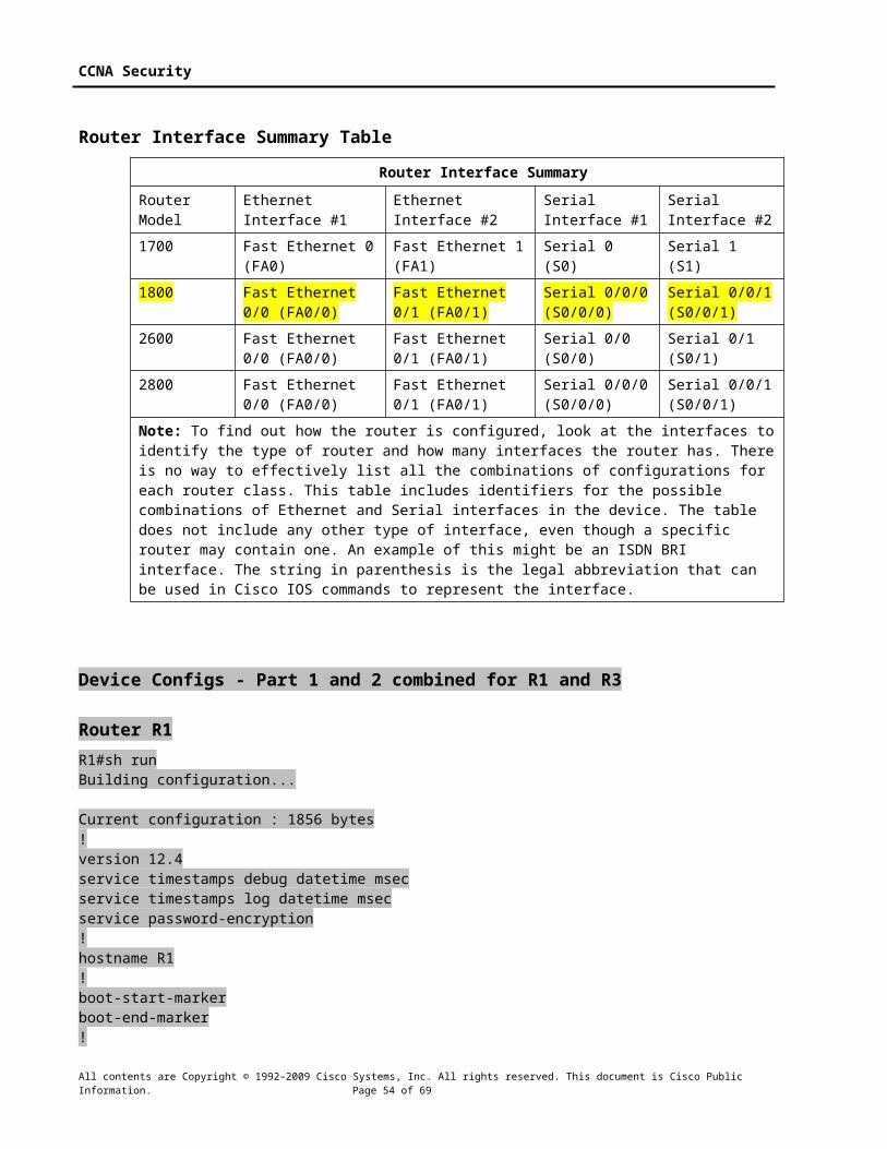
CCNA Security
aaa new-model!aaa authentication login local_authen localaaa authorization exec local_author local!aaa session-id commondot11 syslogno ip source-route!ip cefno ip bootp serverno ip domain lookup!no ipv6 cefmultilink bundle-name authenticated!crypto pki trustpoint TP-self-signed-1301487169 enrollment selfsigned subject-name cn=IOS-Self-Signed-Certificate-1301487169 revocation-check none rsakeypair TP-self-signed-1301487169!!crypto pki certificate chain TP-self-signed-1301487169 certificate self-signed 01 3082023A 308201A3 A0030201 02020101 300D0609 2A864886 F70D0101 04050030 31312F30 2D060355 04031326 494F532D 53656C66 2D536967 6E65642D 43657274 69666963 6174652D 31333031 34383731 3639301E 170D3038 31323231 31363238 33305A17 0D323030 31303130 30303030 305A3031 312F302D 06035504 03132649 4F532D53 656C662D 5369676E 65642D43 65727469 66696361 74652D31 33303134 38373136 3930819F 300D0609 2A864886 F70D0101 01050003 818D0030 81890281 8100CACC 53A913D4 424F2294 B8EAC5BF E4CADFC5 FCBD03D2 C40D6BF7 9B582413 8C478ADC B02FB6BF 481512E1 3BDE9FDE 88DFAFE1 A76621C3 10EBBC35 62D7331E E820D588 8F703464 0FE6258C 96BE38C2 111DAC8C A2D2C800 D61390C0 16CD886C BA036712 E3ADC4F8 DC477457 CEB68C1F 8064C9BD CF3AC037 9DEE8B8D 9906C165 6CF50203 010001A3 62306030 0F060355 1D130101 FF040530 030101FF 300D0603 551D1104 06300482 02523130 1F060355 1D230418 30168014 511FE4C9 4A1A8667 F2BB73CC F3FDCCE3 DE9CBCA7 301D0603 551D0E04 16041451 1FE4C94A 1A8667F2 BB73CCF3 FDCCE3DE 9CBCA730 0D06092A 864886F7 0D010104 05000381 810098BE 697A56AA 40E7D56A AB7C86A2 9A76D57E DD17150E D35382F5 792C6A54 C9272E0C ED0FE4EC 3CFE585D 2C0DE8ED 37BD10F8 49110181 3462D1DC 9E35A052 0C74585C CA2FB05F E965BA45 4BFEBB14 DB07F28C ABE06ECA 0DBBD791 1CF0E3C0 775EB127 65734982 309AD84E 2AE3C3A6 A16B83E5 328F5D2C 3A31D8D4 5E71538C AE34 quit!username admin privilege 15 secret 5 $1$uKGH$dq8qkvBLt5L4nED5bNTK4.archive log config hidekeys!ip tcp synwait-time 10ip ssh time-out 60ip ssh authentication-retries 2!class-map type inspect match-any sdm-cls-insp-traffic match protocol cuseeme match protocol dns match protocol ftp
All contents are Copyright © 1992–2009 Cisco Systems, Inc. All rights reserved. This document is Cisco Public Information. Page 54 of 57

CCNA Security
match protocol h323 match protocol https match protocol icmp match protocol imap match protocol pop3 match protocol netshow match protocol shell match protocol realmedia match protocol rtsp match protocol smtp extended match protocol sql-net match protocol streamworks match protocol tftp match protocol vdolive match protocol tcp match protocol udpclass-map type inspect match-all sdm-insp-traffic match class-map sdm-cls-insp-trafficclass-map type inspect match-any SDM-Voice-permit match protocol h323 match protocol skinny match protocol sipclass-map type inspect match-any sdm-cls-icmp-access match protocol icmp match protocol tcp match protocol udpclass-map type inspect match-all sdm-invalid-src match access-group 100class-map type inspect match-all sdm-icmp-access match class-map sdm-cls-icmp-accessclass-map type inspect match-all sdm-protocol-http match protocol http!!policy-map type inspect sdm-permit-icmpreply class type inspect sdm-icmp-access inspect class class-default passpolicy-map type inspect sdm-inspect class type inspect sdm-invalid-src drop log class type inspect sdm-insp-traffic inspect class type inspect sdm-protocol-http inspect class type inspect SDM-Voice-permit inspect class class-default passpolicy-map type inspect sdm-permit class class-default drop!zone security out-zonezone security in-zonezone-pair security sdm-zp-self-out source self destination out-zone service-policy type inspect sdm-permit-icmpreply
All contents are Copyright © 1992–2009 Cisco Systems, Inc. All rights reserved. This document is Cisco Public Information. Page 55 of 57

CCNA Security
zone-pair security sdm-zp-out-self source out-zone destination self service-policy type inspect sdm-permitzone-pair security sdm-zp-in-out source in-zone destination out-zone service-policy type inspect sdm-inspect!interface Null0 no ip unreachables!interface FastEthernet0/0 no ip address no ip redirects no ip unreachables no ip proxy-arp ip flow ingress shutdown duplex auto speed auto no mop enabled!interface FastEthernet0/1 description $FW_INSIDE$ ip address 192.168.1.1 255.255.255.0 no ip redirects no ip unreachables no ip proxy-arp ip flow ingress zone-member security in-zone duplex auto speed auto no mop enabled!interface FastEthernet0/1/0!interface FastEthernet0/1/1!interface FastEthernet0/1/2!interface FastEthernet0/1/3!interface Serial0/0/0 description $FW_OUTSIDE$ ip address 10.1.1.1 255.255.255.252 no ip redirects no ip unreachables no ip proxy-arp ip flow ingress zone-member security out-zone clock rate 64000!interface Serial0/0/1 no ip address no ip redirects no ip unreachables no ip proxy-arp ip flow ingress shutdown clock rate 2000000!
All contents are Copyright © 1992–2009 Cisco Systems, Inc. All rights reserved. This document is Cisco Public Information. Page 56 of 57

CCNA Security
interface Vlan1 no ip address no ip redirects no ip unreachables no ip proxy-arp ip flow ingress!ip forward-protocol ndip route 0.0.0.0 0.0.0.0 10.1.1.2no ip http serverip http access-class 1ip http authentication localip http secure-server!logging trap debugginglogging 192.168.1.3access-list 1 remark HTTP Access-class listaccess-list 1 remark SDM_ACL Category=1access-list 1 permit 192.168.1.0 0.0.0.255access-list 1 deny anyaccess-list 100 remark SDM_ACL Category=128access-list 100 permit ip host 255.255.255.255 anyaccess-list 100 permit ip 127.0.0.0 0.255.255.255 anyaccess-list 100 permit ip 10.1.1.0 0.0.0.3 anyaccess-list 101 remark VTY Access-class listaccess-list 101 remark SDM_ACL Category=1access-list 101 permit ip 192.168.1.0 0.0.0.255 anyaccess-list 101 deny ip any anyno cdp run
!control-plane!banner login ^CUnauthorized access prohibited^C!line con 0 login authentication local_authen transport output telnetline aux 0 login authentication local_authen transport output telnetline vty 0 4 access-class 101 in authorization exec local_author login authentication local_authen transport input telnet ssh!scheduler allocate 20000 1000end
R1#
All contents are Copyright © 1992–2009 Cisco Systems, Inc. All rights reserved. This document is Cisco Public Information. Page 57 of 57


![CCNA Security 1 - Computer Sciencekotfid/secvoice10/labs/en_CCNAS_Lab_SLM_v10[1].… · CCNA Security 1.0 Student Lab Manual ... use by instructors in the CCNA Security course as](https://img.pdfslide.us/doc/110x75/5a7873db7f8b9a7b698b46df/ccna-security-1-computer-science-kotfidsecvoice10labsenccnaslabslmv101.jpg)