Embed Size (px)
Citation preview
Eilat,Israel,30 November 2010
INVITED TALK
"Currents and Trends on Fiber Sensing Technologies for Structural Health Monitoring"
José
J. M. López-Higuera L. Rodríguez, A. Quintela, and A. Cobo.
Photonic Engineering Group of the University of Cantabria, Avda, Los Castros s/n, E-39005, Santander,
Spain. e-mail contact: [email protected]; phone : 34 942 201498
ABSTRACT A Structural Health Monitoring system (SHM) can be understood as the integration of sensing
intelligence and possibly also actuation devices to allow the loading and damaging conditions
of a structure to be recorded, analysed, localised and predicted in a way that non-destructive
testing becomes an integral part of the structure. It must be consider that the SHM process
involves the observation over time using periodically sampled static and dynamic response
measurements from an array of sensors, the extraction of damage-sensitive features from these
measurements, and the statistical analysis of these features to determine the current state of
system health. Fibre Optic Sensors are very well suited to mach the SHM technical
requirements. In this talk after a very brief introduction of the basic SHM concepts, the currents
of the main fibre optic technologies for this application will be reviewed, several significant
examples addressed, some current technical challenges and the key sector market will also be
identified and, finally, the conclusions summarized.
Keywords: Optical Fibre Sensors, Fiber Optic, Optical Transducers, Optoelectronic Units, Structural health building monitoring.
The Open Access NDT Database
ww
w.ndt.net/?id=
10588
López-Higuera, JM et al; invited paper: Currents and Trends on Fiber Sensing Technologies for SHM.
,Eilat,Israel,30 November 2010
1. INTRODUCTION Good design, quality construction and durable and safe exploitation of structures are goals of structural engineering. However, the structures are subject to adverse changes in their structural health conditions due to potential damages or deterioration induced by environmental degradation, wear, errors in design and construction, current loads, over loads and some unexpected events like earthquakes or impacts or, simply, by their normal working life[1].
Nowadays, there are not quantifiable methods to determine if structures are safe for
reoccupation after a significant overload or an earthquake. The prompt reoccupation of buildings, particularly those associated with manufacturing, can significantly mitigate economic losses associated with major seismic events. In addition, many portions of technical infrastructure are approaching or exceeding their initial design life.
A modern structure must be able to generate and communicate information concerning the
changes in its structural health condition to responsible operators and decision makers, in-time, automatically or on-demand, and reliably. To achieve this targets, a modern structure should be equipped with such kind of system that includes “nervous sub-system”, a “brain” and “voice lines”, which is continuously in operation and able to sense structural conditions. The system should be able to automatically detect the damage, characterize it (recognize, localize, quantify or rate), and report it, providing important input for structure managers or for the system intelligence. The data resulting from a monitoring program can be used to optimize the operation, maintenance, repair and replace of the structure based on reliable and objective data. Such kind of system can be named a Structural Health Monitoring system, SHM.
So, the main aim of SHM systems, similar to the human body, is to detect unusual
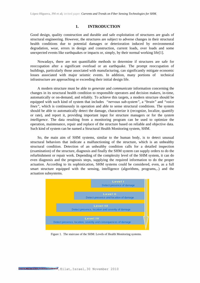
structural behaviors that indicate a malfunctioning of the structure, which is an unhealthy structural condition. Detection of an unhealthy condition calls for a detailed inspection (examination) of the structure, diagnosis and finally the SHM system can supply orders to do the refurbishment or repair work. Depending of the complexity level of the SHM system, it can do even diagnosis and the prognosis steps, supplying the required information to do the proper actuation. According to its sophistication, SHM systems could be considered, even, as a full smart structure equipped with the sensing, intelligence (algorithms, programs,..) and the actuation subsystems.
Figure 1. The staircase of the SHM: Levels of Health Monitoring systems.
Level IDetect presence of damage
Level IIDetect presence and location of damage
Level IIIDetect presence, location and severity of damage
Level IVDetect presence, location, severity and consequences of damage
Level IDetect presence of damage
Level IIDetect presence and location of damage
Level IIIDetect presence, location and severity of damage
Level IVDetect presence, location, severity and consequences of damage

López-Higuera, JM et al; invited paper: Currents and Trends on Fiber Sensing Technologies for SHM.
,Eilat,Israel,30 November 2010
According to the functionality and degree of complexity, the SHM systems can be classified in five levels, in what can be named Staircase of the SHM systems (Figure 1) it can be observed that the higher the level, the higher the complexity and functionality. Level I SHM systems (the simpler one) only detect the presence of damage without locating it. However, the Level IV SHM systems are able to realize the prognosis or to estimate the remaining service life.
The more common parameters to be monitored or measured in this applications are the
Chemical (pH, oxidation, corrosion, carbonation, penetration, timber decay); Mechanical (strain, deformation, displacement, crack opening, stress, load); and Physical (temperature, humidity, pore pressure etc.). For SHM, these parameters can be successfully obtained by optical fiber sensors due to their advantages: Small size, Great variety in the measurable parameters; Distributed and Multiplexed topologies; Insensitive to external perturbations; Reliability in demanding environments; Long-distance remote monitoring; Compatible with data-transmission network.
2. PHOTONIC/OPTICAL/FIBER SENSORS?
The New Photonics Field must be understood as the set of techniques and scientific knowledge which are applied to the generation, propagation, control, amplification, detection, storage and processing of signals of the optical spectrum, along with their technologies and derived uses. The Photonics field can be divided into several areas and that, in many cases, Electronics and Photonics overlap. There are cases where electrons control photons as there are others in which photons control electrons. Therefore, ‘complementary harmony’ can exist between Electronics and Photonics. Within the Photonics field there is an area in which the above-mentioned complementary harmony between both fields is very clear and contributes to enhance the behavior that could now be achieved together: the Photonic Sensing Technology area, in which Optical Fiber Sensing Technology is included [2].
Figure 2.-) Conceptual illustration of an Optical Sensor: Light from the object with its state information encoded in it, after travel through the optical channel, arrives the optoelectronic unit and then the decoded information, in the electrical domain, is able to be used.
Oi
?Oe
López-Higuera, JM et al; invited paper: Currents and Trends on Fiber Sensing Technologies for SHM.
,Eilat,Israel,30 November 2010
As can be deducted from the figure 2, a Photonic/Optical Sensor can be considered as a photonic system of which the measured object magnitude (measurand) or input signal (Oi), introduces modifications or modulations in some of the characteristics of the light in an optical system. After being detected, processed and conditioned, the system will deliver an output signal (Oe), usually in the electric domain, which will be a valid reproduction of the object variable. The transmitted or reflected light can be modulated by the measurand modifying its amplitude, phase, frequency or polarization characteristics. In accordance with this concept, if any of the processes or parts uses fibre-optic technology, a subdivision of OS known as Fiber/Fibre Optic Sensors (FOS), or Optical Fiber/Fibre Sensors (OFS), is created [3]. In the next pages the more successful techniques will be reviewed. Several examples mentioned and then a prospective for the near future of the market and hot topics in which invest research resources will be suggested.
3. OFS SUCCESFUL TECHNIQUES
In the previous years a very wide number or techniques and approaches have been presented to measure a very wide set of measurands in not a less wide number of sectors of application. Many companies were created to exploit commercially the new OFS technologies. However not all of them follow the proper path and survive successfully [4]. In the following lines a very brief review of some of the most successful techniques used will be addressed. They will be structured regarding the fiber structure employed in the transducer and they will be illustrated with an example. 3.1.- Long transducers for elongation measurements Several approaches have been tested for measuring the integral elongation of a structure using long fiber gauges. Typically, these kind of transducers are useful to measure the structural integrity of structures in a wide set of application sectors including architectural heritage and civil engineering applications [5]. When long gauge transducers are required, in the recent years, the most successful technology had been the SOFO system. The transducer consists of a pair of single-mode fibres installed in the structure to be monitored. One of the fibres, called measurement fibre, is in mechanical contact with the host structure. It is attached to it at its two extremities and pre-stressed in-between. On the other hand, the other fibre, the reference fibre, is placed loose in the same pipe. To make an absolute measurement of this path unbalance, a low-coherence double Michelson interferometer is used. The first interferometer is made of the measurement and reference fibres, while the second is contained in the portable reading unit. This second interferometer can introduce, with a scanning mirror, a well-defined path unbalance between its two arms.
López-Higuera, JM et al; invited paper: Currents and Trends on Fiber Sensing Technologies for SHM.
,Eilat,Israel,30 November 2010
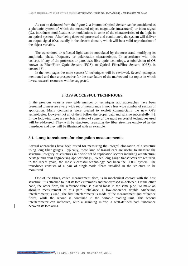
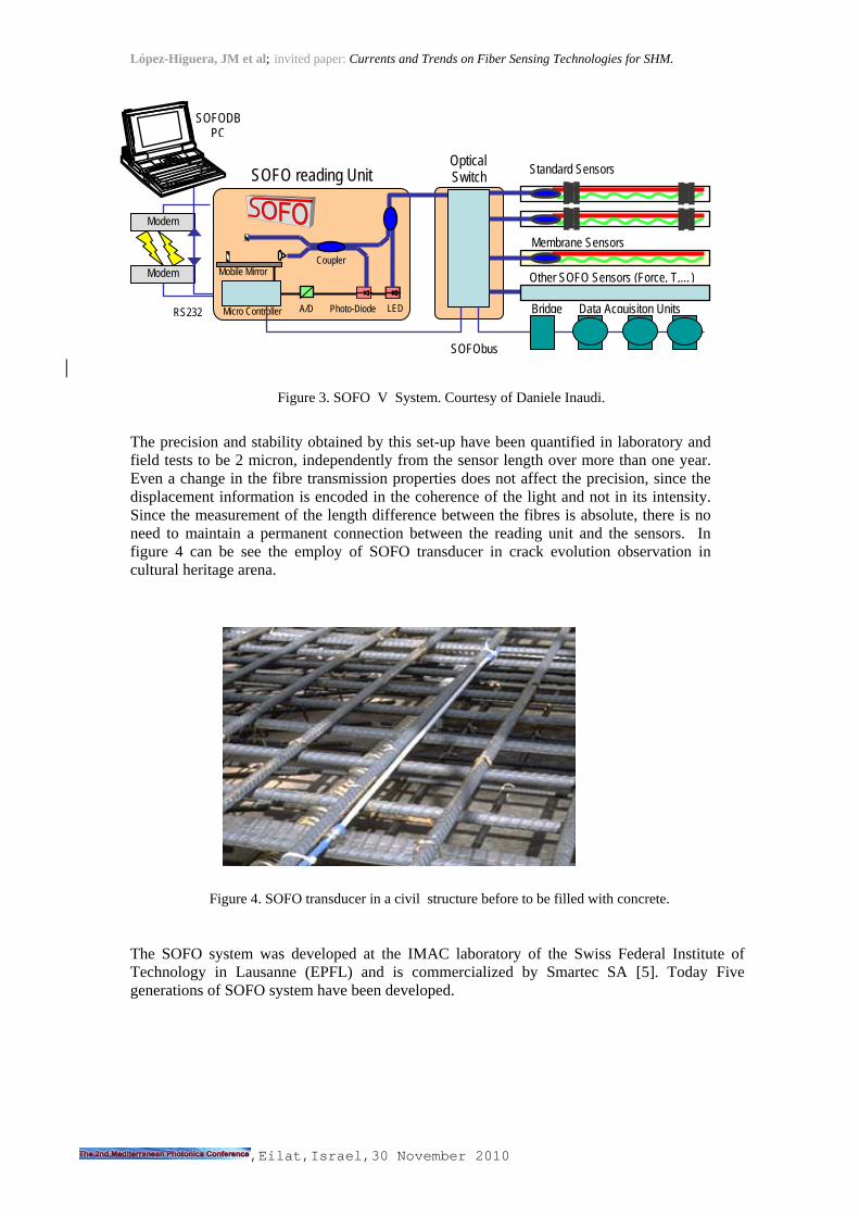
The precision and stability obtained by this set-up have been quantified in laboratory and field tests to be 2 micron, independently from the sensor length over more than one year. Even a change in the fibre transmission properties does not affect the precision, since the displacement information is encoded in the coherence of the light and not in its intensity. Since the measurement of the length difference between the fibres is absolute, there is no need to maintain a permanent connection between the reading unit and the sensors. In figure 4 can be see the employ of SOFO transducer in crack evolution observation in cultural heritage arena. The SOFO system was developed at the IMAC laboratory of the Swiss Federal Institute of Technology in Lausanne (EPFL) and is commercialized by Smartec SA [5]. Today Five generations of SOFO system have been developed.
Figure 3. SOFO V System. Courtesy of Daniele Inaudi.
Figure 4. SOFO transducer in a civil structure before to be filled with concrete.
Modem
Modem
RS232
Data-logger
SOFODB PC
LED A/D
Coupler
Photo-Diode
Mobile Mirror
SOFO reading Unit
Micro Controller
Optical Switch
SOFObus
Standard Sensors
Membrane Sensors
Other SOFO Sensors (Force, T,…)
Bridge Data Acquisiton Units

López-Higuera, JM et al; invited paper: Currents and Trends on Fiber Sensing Technologies for SHM.
,Eilat,Israel,30 November 2010
3.2.- Fabry-Perot cavities to measure punctual measurands Fabry-Perot cavities (both passive and active) have been very successfully used in sensing applications exploiting measurand-induced changes in one of their cavity parameters. They can be used both as the basis for the transducer mechanism or as fixed or tunable devices in the optoelectronic unit. The cavity can be active, for instance integrating a fibre laser sensor, or passive. One very well tested approach is the Extrinsic Fabry-Perot Interferometers (EFPI's) that is constituted by a capillary silica tube containing two cleaved optical fibres facing each other, but leaving an air gap of a few microns or tens of microns between them. When light is launched into one of the fibres, a back-reflected interference signal is obtained. This is due to the reflection of the incoming light on the glass-to-air and on the air-to-glass interfaces (figure 5).
This interference can be demodulated using coherent or low-coherence techniques to reconstruct the changes in the fibre spacing [6].This structure were used in a wide set of applications to measure an ample set of measurands. For instance in a sensor head [7, 8]for long-term high-precision strain measurements of very small deformations of a mechanical diaphragm and in a fiber-optic strain sensor [9], in an in-vitro and in-situ immunoassay biosensor based on fibre optic Fabry-Perot interferometer are described, respectively. Because of its nano-size and high sensitivity to many parameters (strain, pressure, vibration, chemical- humidity, breathing, etc,-) the FP cavities obtained by molecular self-assembly chemistry have obtained a special attention in the last decade [10, 11]. NanoFabry-Perot cavity used to measure humidity have been developd. The cavity is made at the end of the fiber and it reacts with the measurand: humidity, strain, pressure and even with the human breathing.
Figure 6.- Commertial Transducers based on Fabry-Perot Cavities. Left for pressure; right for displacement. Courtesy of Roctest.
Figure 5.- Ilustration of a Fabry-Perot cavity in fiber technology.
Optical Fiber Mirror
Cavity

López-Higuera, JM et al; invited paper: Currents and Trends on Fiber Sensing Technologies for SHM.
,Eilat,Israel,30 November 2010
Commercial FP transducers and devices can be found from several companies. Some technical characteristics of the commercial reading units marketed by Roctest are Resolution: Strain 0.1 ; Temperature 0.1 °C; Pressure 0.1 KPa; Displacement 20 m. Measurement speed: 1Hz, 100 Hz or 500 Hz. Max number of channels: 1, 4, 8, 16 or 32. 3.3.-In-fibre gratings for quasi-distributed measurements Gratings written in the core of optical fibres are one of the more intensively studied structures because of their great possibilities to create devices for both sensing and telecommunication applications [12]. Their optical, mechanical and environmental (in wide sense) behaviors, among others, were studied both as a base for transducers and/or as a base for optical devices for optoelectronic units or optical communications systems or subsystems [13].
In sensing, both short period (Bragg) and long period (period much longer than the wavelength of the light) are used. The first one because of their capability to measure both the strain and temperature of a structure (and an ample variety of indirect measurands). Besides, they are also widely used because of their ability to create tunable filters and for their multiplexing capabilities. Long period gratings are used because of its high sensitivity to the cladding modes (among others). A very simplified illustration and explanation of how the fiber grating structure works can be found in the figure 7.
Figure 7. Illustration of the response of a fiber grating when it is interrogated with a white light source. If it is a short period grating (named Bragg Gratings) a narrow portion of the light is reflected having its peak at the Bragg Wavelength (lB). The rest of the light continues traveling through the fiber. However, if it is a Long Period Grating (LPG) the grating works only in transmission and dips on the spectrum can be observed. Short period when the grating period is small that the light interrogation wavelength. Long period when is many times ( ej. 100 times) the light wavelength.

López-Higuera, JM et al; invited paper: Currents and Trends on Fiber Sensing Technologies for SHM.
,Eilat,Israel,30 November 2010
This technology can be used in aerospace, medical, biomedical, environmental applications, electric power energy, and in military and civil engineering applications sectors. A complete civil structure monitoring system fully designed, developed, in-laboratory and in-field tested system can be found in [14]. A detail of the embedding process of a fiber Bragg grating transducer installed in Las Navas Bridge of the A8 highway in Cantabria, Spain, is shown in figure 8.
Figure 8.- Temperature and Strain grating Transducer being embedded in Concrete. Courtesy of the Photonic Engineering Group of the University of Cantabria. Another example of quaisidistributed sensing is illustrated in figure 9. Before to start with with the rehabilitation works measuremets of the structurals state of the tower in the Mayor Seminary of Comillas, Cantabria Spain, a quasidistributed network of sensors based on Bragg Grating technology were deployed to measure the strain and elongations during a period of time.
Figure.9.- Illustration of the quasidistributed network of sensors based on Bragg Grating technology were deployed during the rehabilitation of the mayor seminary tower in Comillas. Courtesy of the Photonic Engineering Group of the University of Cantabria.

López-Higuera, JM et al; invited paper: Currents and Trends on Fiber Sensing Technologies for SHM.
,Eilat,Israel,30 November 2010
Fig. 10. Bragg gratings transducers from Fibersensing: temperature (a) strain (b), acceleration (c), Pressure (d), and displacement (e). Optoelectronic units: from Micron Optics (f) from FOSS (g) and Fibersensing (h).
Despite of its relative novelty, fibre grating technology is enough mature and several sensing
companies have their core business centred in it. New studies looking for new effects and structures continue [15].
3.4.-Distributed sensing
Due to optical fibre properties in addition with advanced interrogation techniques, distributed sensing in which the fibre acts, simultaneously, as optical channel and distributed transducer is, today a reality. It can be said that the fibre play the role of a “nerve” for materials and structures in which the fibre is embedded. Distributed optical-fibre sensor systems have and, undoubtedly, will have a large role to play in the monitoring and diagnostics of what can be called “smart materials and structures” [16]. Linear backscattering and overall, non-linear back-scattering and non-linear forward-scattering (having their own special advantages and disadvantages) can be used to match the specific requirements of length and resolution of the measurand. Raman scattering (for temperature) and Brillouin scattering (for strain and/or temperature) or their combination [17] using time, frequency, polarization, or correlation domain techniques (continuous or pulsed) including several variants [18], are used to interrogate the distributed transducer [19].
Fig. 11. Illustration of the scattering effect. A pulse of light is traveling into the fiber. In some part of the fiber scattering is provoked. Then a very low power pulse is traveling backward to the optoelectronics. As the speed of light into the fiber is known the flight time of the very weak returned pulse is measured and hence the
a) b)
c) d) e)
f) g)
h)
López-Higuera, JM et al; invited paper: Currents and Trends on Fiber Sensing Technologies for SHM.
,Eilat,Israel,30 November 2010
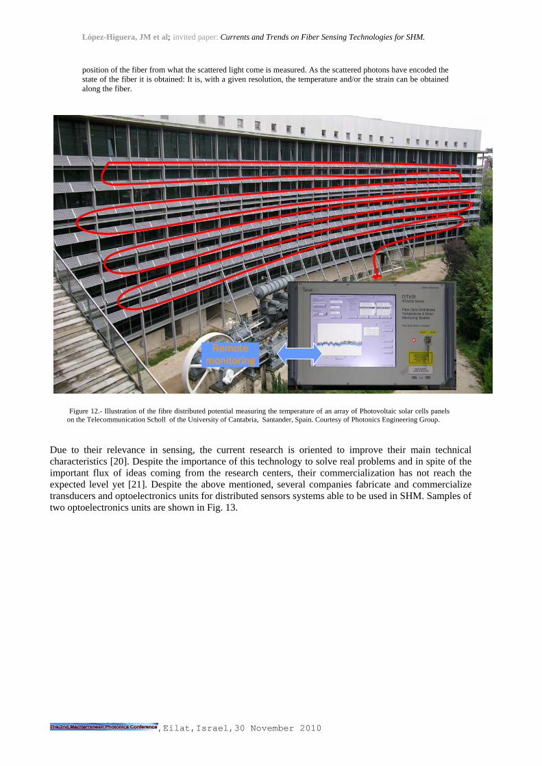
position of the fiber from what the scattered light come is measured. As the scattered photons have encoded the state of the fiber it is obtained: It is, with a given resolution, the temperature and/or the strain can be obtained along the fiber.
Due to their relevance in sensing, the current research is oriented to improve their main technical characteristics [20]. Despite the importance of this technology to solve real problems and in spite of the important flux of ideas coming from the research centers, their commercialization has not reach the expected level yet [21]. Despite the above mentioned, several companies fabricate and commercialize transducers and optoelectronics units for distributed sensors systems able to be used in SHM. Samples of two optoelectronics units are shown in Fig. 13.
Remote monitoring
Figure 12.- Illustration of the fibre distributed potential measuring the temperature of an array of Photovoltaic solar cells panels on the Telecommunication Scholl of the University of Cantabria, Santander, Spain. Courtesy of Photonics Engineering Group.

López-Higuera, JM et al; invited paper: Currents and Trends on Fiber Sensing Technologies for SHM.
,Eilat,Israel,30 November 2010
Fig. 13. Two optoelectronic unit (lower place).). DiTest Brillouin (left hand) and Raman (right hand) scattering interrogation units. Courtesy of Smartech, Omnisens and Sensornet.
Some of the commercial companies are: i) based on Brillouin scattering: Omnisens (www.ommnisens.ch), ANDO (tmi.yokogawa.com), Sensornet (www.sensoret.co.uk), and Neubrex (www.neubrex.com) and OZ Optics (www.ozoptics.com); ; ii) Based on Raman to measure distributed temperature (DTS): Sensa-Shlumberger (www.sensa.org), Agilent (www.agilent.com), and Sensornet; iii) based on Raman scattering Luna Technologies (www.lunatechnologies.com). Specific cables for sensing are produced by SMARTEC (www.smartec.ch).
4. TECHNICAL CHALLENGES
Several challenged topics must be properly treated and their difficulties removed. It is necessary to guarantee that the data from the sensors represent the real behavior of the material or the structure and are not corrupted due to a sensor malfunction. This drives to the following key topics: Inner sensor failure detection…. . It will be necessary to monitor the sensors themselves. Measurement errors…. (to decrease the crossed sensitivities, environmental effects ..) Data interpretation techniques..(often lead to inverse problems. Correlation of analytical model
to actual structure,.. using SHM data,..) Lack of standards & specifications Improved, new and cost-effective sensors…
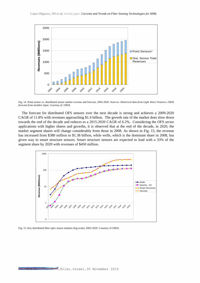
5. OFS MARKET As OFS are key devices for SHM, some comments about their future market will be given. According to the OIDA studies [22], the OFS market is expected to grow strongly over the decade 2009-2020 with a Compound Annual Growth Rate (CAGR) of 9.8% and achieve revenues of $1.95 billion by 2020. As shown in Fig. 14, the share of this global OFS market can be considered composed by the point and the distributed OFS (including in the later the quasidistributed ones). The distributed sensor market grew 40% and $302 million revenue in 2007, and 26% with $382 million revenue in 2008.
Courtesy of Photonic E
López-Higuera, JM et al; invited paper: Currents and Trends on Fiber Sensing Technologies for SHM.
,Eilat,Israel,30 November 2010
0
500
1000
1500
2000
2500
2002
2004
2006
2008
2010
2012
2014
2016
2018
2020
Reven
ues (
$M
illio
ns)
Point Sensors*
Dist. Sensor TotalRevenues
Fig. 14. Point sensor vs. distributed sensor market revenue and forecast, 2002-2020. Sources: Historical data from Light Wave Ventures, OIDA forecast from member input. Courtesy of OIDA.
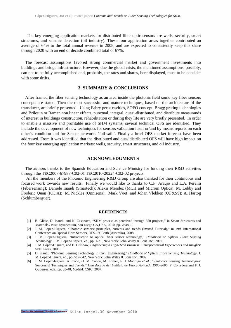
The forecast for distributed OFS sensors over the next decade is strong and achieves a 2009-2020
CAGR of 11.8% with revenues approaching $1.4 billion. The growth rate of the market does slow down towards the end of the decade and reduces to a 2015-2020 CAGR of 6.2%. Considering the OFS sector applications with higher shares and growths, it is observed that at the end of the decade, in 2020, the market segment shares will change considerably from those in 2008. As shown in Fig. 15, the revenue has increased from $380 million to $1.38 billion, while wells, which is the dominant share in 2008, has given way to smart structure sensors. Smart structure sensors are expected to lead with a 33% of the segment share by 2020 with revenues of $450 million.
0
1
10
100
1000
2002
2003
2004
2005
2006
2007
2008
2009
2010
2011
2012
2013
2014
2015
2016
2017
2018
2019
2020
Reven
ue (
$M
illio
ns)
Wells
Seismic - Oil
Smart Structures
Security
Fig. 15. Key distributed fiber optic sensor markets (log scale), 2002-2020. Courtesy of OIDA.
López-Higuera, JM et al; invited paper: Currents and Trends on Fiber Sensing Technologies for SHM.
,Eilat,Israel,30 November 2010
The key emerging application markets for distributed fiber optic sensors are wells, security, smart
structures, and seismic detection (oil industry). These four application areas together contributed an average of 64% to the total annual revenue in 2008, and are expected to consistently keep this share through 2020 with an end of decade combined total of 67%.
The forecast assumptions favored strong commercial market and government investments into
buildings and bridge infrastructure. However, due the global crisis, the mentioned assumptions, possibly, can not to be fully accomplished and, probably, the rates and shares, here displayed, must to be consider with some drifts.
3. SUMMARY & CONCLUSIONS
After framed the fiber sensing technology as an area inside the photonic field some key fiber sensors concepts are stated. Then the most successful and mature techniques, based on the architecture of the transducer, are briefly presented. Using Fabry perot cavities, SOFO concept, Bragg grating technologies and Brilouin or Raman non linear effects, punctual, integral, quasi-distributed, and distribute measurands of interest in buildings construction, rehabilitation or during they life are very briefly presented. In order to enable a massive and profitable use of SHM systems, several technical OFS are identified. They include the development of new techniques for sensors validation itself or/and by means reports on each other’s condition and for Sensor networks ‘fail-safe’. Finally a brief OFS market forecast have been addressed. From it was identified that the distributed and quasidistributed OFS will have high impact on the four key emerging application markets: wells, security, smart structures, and oil industry.
ACKNOWLEDGMENTS
The authors thanks to the Spanish Education and Science Ministry for funding their R&D activities
through the TEC2007-67987-C02-01 TEC2010-20224-C02-02 projects. All the members of the Photonic Engineering R&D Group are also thanked for their continuous and
focused work towards new results. Finally we would like to thanks to C.F. Araujo and L.A. Pereira (Fibersensing); Daniele Inaudi (Smartech); Alexis Mendez (MCH and Microm Optics); M. Lebby and Frederic Quan (IODA); M. Nickles (Onnisens); Mark Voet and Johan Vlekken (OF&SS); A. Hartog (Schlumberguer).
REFERENCES
[1] B. Glisic, D. Inaudi, and N. Casanova, “SHM process as perceived through 350 projects,” in Smart Structures and Materials / NDE Symposium, San Diego CA,USA, 2010, pp. 76480P.
[2] J. M. Lopez-Higuera, “Photonic sensors: principles, currents and trends (Invited Tutorial),” in 19th International Conference on Optical Fibre Sensors, OFS-19, Perth (Australia), 2008.
[3] J. M. Lopez-Higuera, "Introduction to optical fiber sensor technology," Handbook of Optical Fibre Sensing Technology, J. M. Lopez-Higuera, ed., pp. 1-21, New York: John Wiley & Sons Inc., 2002.
[4] J. M. López-Higuera, and B. Culshaw, Engineering a High-Tech Business: Entrepreneurial Experiences and Insights: SPIE Press, 2008.
[5] D. Inaudi, "Photonic Sensing Technology in Civil Engineering," Handbook of Optical Fibre Sensing Technology, J. M. Lopez-Higuera, ed., pp. 517-542, New York: John Wiley & Sons Inc., 2002.
[6] J. M. Lopez-higuera, A. Cobo, O. M. Conde, M. Lomer, F. J. Madruga et al., "Photonics Sensing Technologies: Successful Techniques and Trends," Una decada del Instituto de Física Aplicada 1995-2005, P. Corredera and F. J. Gutierrez, eds., pp. 33-48, Madrid: CSIC, 2007.
López-Higuera, JM et al; invited paper: Currents and Trends on Fiber Sensing Technologies for SHM.
,Eilat,Israel,30 November 2010
[7] E. Cibula, and D. Donlagic, “All-fiber Fabry-Perot strain sensor,” Second European Workshop on Optical Fibre Sensors: Proceedings, vol. 5502, pp. 180-183, 2004.
[8] D. Hofmann, F. Basedau, W. R. Habel, and R. Gloetzl, “Lightning-safe diaphragm pressure gauge for geotechnical
applications using a long-term reliable absolute EFPI sensor,” Second European Workshop on Optical Fibre Sensors: Proceedings, vol. 5502, pp. 128-131, 2004.
[9] C. J. Lin, Y. T. Tseng, S. C. Lin, C. S. Yang, and F. G. Tseng, “A novel in vitro and in situ immunoassay biosensor based on fiber optic Fabry-Perot interferometry,” in Second European Workshop on Optical Fibre Sensors: Proceedings, Santander, 2004, pp. 304.
[10] F. J. Arregui, K. L. Cooper, Y. J. Liu, I. R. Matias, and R. O. Claus, “Optical fiber humidity sensor with a fast response time using the ionic self-assembly method,” Ieice Transactions on Electronics, vol. E83C, no. 3, pp. 360-365, 2000.
[11] R. Claus, J. Lalli, J. Mecham, B. Davis, A. Hill et al., “Self-assembled nanostructured optical fiber sensors,” 17th International Conference on Optical Fibre Sensors, Pts 1 and 2, vol. 5855, pp. 138-141, 2005.
[12] R. Kashyap, Fiber bragg gratings: Academic Pr, 1999. [13] S. T. Vohra, "Optical fiber gratings Applications," Handbook of Optical Fibre Sensing Technology, J. M. Lopez-
Higuera, ed., pp. 475-504, New York: John Wiley & Sons Inc., 2002. [14] J. M. Lopez-Higuera, C. J. Misas, A. Q. Incera, and J. E. Cuenca, “Fiber optic civil structure monitoring system,”
Optical Engineering, vol. 44, no. 4, 2005. [15] C. Jáuregui, and J. M. López-Higuera, “Virtual long-period gratings,” Opt. Lett., vol. 30, no. 1, pp. 14-16, 2005. [16] A. J. Rogers, "Distributed Optical-fiber Sensing," Handbook of Optical Fibre Sensing Technology, J. M. Lopez-
Higuera, ed., pp. 271-308, New York: John Wiley & Sons Inc., 2002. [17] M. N. Alahbabi, Y. T. Cho, and T. P. Newson, "Simultaneous distributed measurements of temperature and strain
using spontaneous Raman and Brillouin scattering," Second European Workshop on Optical Fibre Sensors: Proceedings, Proceedings of the Society of Photo-Optical Instrumentation Engineers (Spie) J. Miguel and B. Culshaw, eds., pp. 488-491, Bellingham: Spie-Int Soc Optical Engineering, 2004.
[18] S. J. Russell, and et al., “A novel method for location of buried optical cables, where an incident EM wave modulates the polarization of guided light, using the Faraday effect,” Measurement Science and Technology, vol. 15, no. 8, pp. 1651, 2004.
[19] D. Alasia, M. G. Herraez, L. Abrardi, S. M. Lopez, and L. Thevenaz, "Detrimental effect of modulation instability on distributed optical fibre sensors using stimulated Brillouin scattering," 17th International Conference on Optical Fibre Sensors, Pts 1 and 2, Proceedings of the Society of Photo-Optical Instrumentation Engineers (Spie) M. Voet, R. Willsch, W. Ecke et al., eds., pp. 587-590, Bellingham: Spie-Int Soc Optical Engineering, 2005.
[20] L. Thévenaz, and et al., “Novel schemes for optical signal generation using laser injection locking with application to Brillouin sensing,” Measurement Science and Technology, vol. 15, no. 8, pp. 1519, 2004.
[21] K. Hotate, “Distributed optical fibre sensors and their applications, (Invited Tutorial),” in 19th International Conference on Optical Fibre Sensors, OFS-19, Perth ,Australia, 2008.
[22] Global Optoelectronics Industry Market Report and Forecast: Optoelectronics Industry Development Association (OIDA), 2009.