Embed Size (px)
Citation preview
Current Transformers, Switches, Transmitters
Solid State Switch ModelsNon-polarity sensitive magnetically isolated solid state switch
Mechanical Relay Models5 A Isolated SPDT mechanical relay, 3 A inductive
HysteresisApproximately 5% of setpoint
Response TimeCS-AC: 120 millisecondsCS-DC: 100 milliseconds (10% above setpoint) 20 milliseconds (100% above setpoint)
Economical and easy-to-install sensors for monitor-ing current out-of-limit conditions
Process Limit or Motor Over-Current Alarm
Heater Break or Conveyor Jam Alarm
CS AC and DC Current Switches Input: Up to 150 Amps AC, 100 Amps DC Output: SPDT Relay or NC or NO SSR
CS-AC IndicationNormal operation: Red LED flashes every 2-3 secondsAlarm: Red LED flashes 2-3 times per second
CS-DC IndicationGreen LED indicates when unit is onRed LED turns on above trip point
External DimensionsCS-AC: 3.53" W x 2.47" H x 1.19" DCS-DC: 3.88" W x 2.9" H x 1.5" D
IsolationCS-AC: 1270 VAC CS-DC: 3 kV
PowerAC: powered by 4-20 mA current loop DC: externally powered
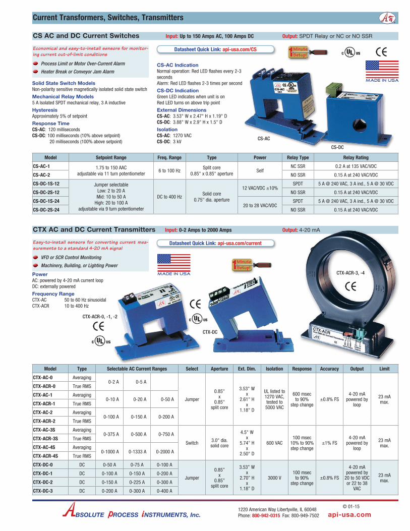
Frequency RangeCTX-AC 50 to 60 Hz sinusoidal CTX-ACR 10 to 400 Hz
Easy-to-install sensors for converting current mea-surements to a standard 4-20 mA signal
VFD or SCR Control Monitoring
Machinery, Building, or Lighting Power
Model Type Selectable AC Current Ranges Select Aperture Ext. Dim. Isolation Response Accuracy Output Limit
CTX-AC-0 Averaging 0-2 A 0-5 A
Jumper
0.85" x
0.85"split core
3.53" W x
2.61" H x
1.18" D
UL listed to 1270 VAC, tested to 5000 VAC
600 msec to 90%
step change±0.8% FS
4-20 mA powered by
loop
23 mA max.
CTX-ACR-0 True RMS
CTX-AC-1 Averaging 0-10 A 0-20 A 0-50 A
CTX-ACR-1 True RMS
CTX-AC-2 Averaging 0-100 A 0-150 A 0-200 A
CTX-ACR-2 True RMS
CTX-AC-3S Averaging 0-375 A 0-500 A 0-750 A
Switch 3.0" dia. solid core
4.5" W x
5.74" H x
2.50" D
600 VAC100 msec
10% to 90% step change
±1% FS4-20 mA
powered by loop
23 mA max.
CTX-ACR-3S True RMS
CTX-AC-4S Averaging 0-1000 A 0-1333 A 0-2000 A
CTX-ACR-4S True RMS
CTX-DC-0 DC 0-50 A 0-75 A 0-100 A
Jumper
0.85” x
0.85”split core
3.53” W x
2.70” H x
1.18” D
3000 V100 msec
to 90% step change
±0.8% FS
4-20 mA powered by
20 to 50 VDC or 22 to 38
VAC
23 mA max.
CTX-DC-1 DC 0-100 A 0-150 A 0-200 A
CTX-DC-2 DC 0-150 A 0-225 A 0-300 A
CTX-DC-3 DC 0-200 A 0-300 A 0-400 A
CTX AC and DC Current Transmitters Input: 0-2 Amps to 2000 Amps Output: 4-20 mA
Datasheet Quick Link: api-usa.com/current
Model Setpoint Range Freq. Range Type Power Relay Type Relay Rating
CS-AC-1 1.75 to 150 AAC adjustable via 11 turn potentiometer
6 to 100 HzSplit core
0.85" x 0.85" apertureSelf
NC SSR 0.2 A at 135 VAC/VDC
CS-AC-2 NO SSR 0.15 A at 240 VAC/VDC
CS-DC-1S-12 Jumper selectable Low: 2 to 20 A Mid: 10 to 50 A
High: 20 to 100 A adjustable via 9 turn potentiometer
DC to 400 HzSolid core
0.75" dia. aperture
12 VAC/VDC ±10%SPDT 5 A @ 240 VAC, 3 A ind., 5 A @ 30 VDC
CS-DC-2S-12 NO SSR 0.15 A at 240 VAC/VDC
CS-DC-1S-2420 to 28 VAC/VDC
SPDT 5 A @ 240 VAC, 3 A ind., 5 A @ 30 VDC
CS-DC-2S-24 NO SSR 0.15 A at 240 VAC/VDC
Datasheet Quick Link: api-usa.com/CS
CTX-ACR-0, -1, -2
CTX-ACR-3, -4
CS-DC
CS-AC
Minute Setup!1
Minute Setup!1
api-usa.com1220 American Way Libertyville, IL 60048 Phone: 800-942-0315 Fax: 800-949-7502BSOLUTE ROCESS NSTRUMENTS, Inc.
© 01-15
H H H H H H H H H H H H H H H H H H H H H H H H H H H H H H H H H H H H H H H H H H H H H H H H H H
Made in USA
H H H H H H H H H H H H H H H H H H H H H H H H H H H H H H H H H H H H H H H H H H H H H H H H H H
Made in USA
CTX-DC

T201 Series
Highlights• Selectable Input current up
to 300A
• Loop powered modelsavailable
• Very low powerconsumption (< 22 mA)
• Rated analog output 0..20mA or 0..10 V versions
• AC/DC TRMS or bipolarmeasurement
• Accuracy class 0,5% [AC] /1% [DC]
• Wide operating temperaturerange (-20..+70°C)
• UL certification
T201 Series includes AC/DC current trasducers designed to
convert measured current value (up to 300 A) into a 4..20 mA or
0..10 V industrial normalized signal. T201 Series is UL certified
and it is characterized by low power consumption, measuring
range freely settable via DIP-switches and high accuracy class
avoiding thermal drift. T201 Series is available in 9 models
with different measuring principles: average rectified, magnetic
balance (patented technology), Hall Effect or TRMS with bipolar
input range.
w w w . s e n e c a . i t
100%
M
ade & Designed in Italy
AC/DC CURRENT TRANSDUCERS

SENECA I T201 Series
AC/DC CURRENT TRANSDUCERS – T201 SERIES
T201 Series AC/DC Current Transformers
The Transducers that use the measurement based on magnetic induction technology are long life devices thanks to the principle of measurement that avoids thermal drifts and which exploits the generation of an induced current on the transducer output, through the variation of a magnetic field. A direct use will be possible without any external shunts, even for pulsed currents.
When a magnetic field is applied perpendicularly to a conductor, a voltage is generated transversally to the direction of the current flow. The Hall Effect Current Transducers are used as alternative to shunt when dealing with high voltages and high galvanic isolation.
MAGNETIC INDUTION
HALL EFFECT
DIRECT USE WITHOUT SHUNT FOR PULSE CURRENT
COMPACT DIMENSION
WIDE CONFIGURATION RANGE
ACCURACY CLASS: 0,2 / 0,5 %
ENERGY EFFICIENCY UL CERTIFICATIONLoop power supply /auxiliary power
supply Low consumption < 21 mA
SELECTABLE CURRENTOUTPUT: VOLTAGE (V) OR CURRENT (mA)
Wide range input through dip-switches from 5 A to 40 / 100 / 300 A, single or double polarity Output: Voltage (V) or Current (mA)

SENECA I T201 Series
AC/DC CURRENT TRANSDUCERS – T201 SERIES
GENERAL DATAPower supply Loop powered (5..28 Vdc) Loop powered (6..100 V) Loop powered (6..100 V)Power consumption < 21 mA < 21 mA < 21 mAIsolation / protection 3 kVdc (on bare conductors) 3 kVdc (on bare conductors) 3 kVdc (on bare conductors)
Installation category300 V CAT III (bare conductor);600 V CAT III (bare conductor)
300 V CAT III (bare conductor);600 V CAT III (bare conductor)
300 V CAT III (bare conductor);600 V CAT III (bare conductor)
Measurement polarity Positive (incoming current on label side) Positive (incoming current on label side) Positive (incoming current on label side)Protection degree IP20 IP20 IP20Response time 100 ms (without filter) 2,5 s (with filter) 100 ms (without filter) 600 ms (with filter) 100 ms (without filter) 600 ms (with filter)Accuracy class AC: 0,2% f.s. DC: 0,2% f.s. DC: 0,2% f.s.Thermal drift < 150 ppm/K < 150 ppm/K < 150 ppm/KSettings DIP switch DIP switch DIP switchOperating temperature -20..+65°C -10..+65°C -10..+65°CStorage temperature -40..+85°C -40..+85°C -40..+85°CHumidity 10..90%RH non condensing 10..90%RH non condensing 10..90%RH non condensingConnections Removable terminals Removable terminals Removable terminalsMax diameter conductor 12, 5 mm 12,5 mm 17 mmDimension 54 x 41 x 30 mm 54 x 41 x 30 mm 68 x 97 x 26 mmMounting 35 mm DIN rail with adapter 35 mm DIN rail with adapter 35 mm DIN rail with adapterWeight 50 g 50 g 100 g
INPUT DATAChannels 1 1 1Range 5, 10, 15, 20, 25, 30, 35, 40 A Monopolar 0..5, 0..10, 0..20,0.. 40 A
Bipolar -5..5, -10..10, -5..20, -10..40 AMonopolar 0..10, 0..25, 0..50, 0..100 A Bipolar --5..5, -10..10, -5..20, -10..40 A A
Measurement type Average adjusted Magnetic balance Magnetic balanceBipolar measurement No Yes YesHysteresisMax instantaneous overcurrent 800 A 800 A 2000 A (impulsive)Bandwidth / frequency 20..1.000 Hz n.d. n.d.Crest factor 2 1,2 1,2
OUTPUT DATAChannels 1 1 1Range 4..20 mA (2 wires) 4..20 mA (2 wires) 4..20 mA (2 wires)Resolution Unlimited 12 bit 12 bitMax load < 5000 Ohm @ 100 Vdc
STANDARDApprovals CE, UL-UR CE, UL-UR, european patent CE, UL-UR, european patentNorms EN60688
EN61000-6-4EN61000-6-2EN61010-1
EN61000-6-4EN61000-6-2EN61010-1
EN61000-6-4EN61000-6-2EN61010-1
ORDER CODES
ModelT201
AC current transducer to DC current (4..20 mA - loop powered)
T201DCDC current transducer to DC current
(4..20 mA - loop powered)
T201DC100Passive current transducer 100 Adc
for 4..20 mA current loopSPARE PARTSA-DIN-T201 DIN rail Plastic clip for T201
AC/DC CURRENT TRANSDUCERS WITH 4-20 mA OUTPUT
T201 T201DC T201DC100
AC current transducer to DC current (4..20 mA - loop powered)
DC current transducer to DC current (4..20 mA - loop powered)
Passive current transducer 100 Adc for 4..20 mA current loop
Patentedtechnology
Patentedtechnology
Technical data, diagrams and drawings in this brochure are indicative only and not binding

SENECA I T201 Series
AC/DC CURRENT TRANSDUCERS – T201 SERIES
AC/DC HALL EFFECT CURRENT TRANSDUCERS
T201DCH T201DCH100 T201DCH300
AC/DC contactless TRMS direct and alternate current transducer
AC/DC contactless TRMS direct and alternate current (± 100 A) transducer, Hall Effect
AC/DC contactless TRMS direct and alternate current (± 300 A) transducer, Hall Effect
HALL EFFECT
HALL EFFECT
HALL EFFECT
GENERAL DATAPower supply 10..28 Vdc 12..28 Vdc 12..28 VdcPower consumption < 25 mA < 25 mA < 25 mAIsolation / protection 3 kVdc (on bare conductors) 3 kVdc (on bare conductors) 3 kVdc (on bare conductors)
Installation category300 V CAT III (bare conductor);600 V CAT III (bare conductor)
300 V CAT III (bare conductor);600 V CAT III (bare conductor)
300 V CAT III (bare conductor);600 V CAT III (bare conductor)
Measurement polarity Positive (incoming current on label side) Positive (incoming current on label side) Positive (incoming current on label side)Protection degree IP20 IP20 IP20Response time Fast filter: 800 ms - Slow filter: 2 s Fast filter: 800 ms - Slow filetr: 2 s Fast filter: 800 ms - Slow filetr: 2 s
Accuracy classAC: 0,5% f.sDC: 1% f.s.
AC: 0,5% f.s.DC: 1% f.s.
AC: 0,5% f.s,DC: 1% f.s.
Thermal drift < 200 ppm/K < 200 ppm/K < 200 ppm/KSettings DIP switch DIP switch DIP switchOperating temperature -10..+65°C -20..+70°C -20..+70°CStorage temperature -40..+85°C -40..+85°C -40..+85°CHumidity 10..90%RH non condensing 10..90%RH non condensing 10..90%RH non condensingConnections Removable terminals Removable terminals Removable terminalsMax diameter conductor 20,5 mm 20,5 mm 20,5 mmDimension 54 x 41 x 30 mm 68 x 97 x 26 mm 68 x 97 x 26 mmMounting 35 mm DIN rail with adapter 35 mm DIN rail with adapter 35 mm DIN rail with 2 adapters / screwsWeight 50 g 100 g 100 g
INPUT DATAChannels 1 1 1Range 0..25, 0..50 Aac/dc TRMS 0-50 A, 0-100 Aac/dc TRMS;
±50 A, ±100 A Bipolar0-150 A, 0-300 Aac/dc TRMS;±150 A, ±300 A Bipolar
Measurement type TRMS AC/DC TRMS or DC Bipolar AC/DC TRMS or DC BipolarBipolar measurement No Yes YesHysteresis 0,1 % f.s. 0,1 % f.s. 0,1 % f.s.Max instantaneous overcurrent 2000 A (impulsive) 2000 A (impulsive) 2000 A (impulsive)Bandwidth / frequency 1 kHz 1 kHz 1 kHzCrest factor 1,2 2 2
OUTPUT DATAChannels 1 1 1Range 0..10 V 0..10 V 0..10 VResolution 12 bit 12 bit 12 bitMax load > 2 kOhm > 2 kOhm > 2 kOhm
STANDARDApprovals CE, UL-UR CE, UL-UR CE, UL-URNorms EN61000-6-4
EN61000-6-2EN61010-1
EN61000-6-4EN61000-6-2EN61010-1
EN61000-6-4EN61000-6-2EN61010-1
ORDER CODES
ModelT201DCH
AC/DC contactless TRMS direct and alternate current transducer
T201DCH100AC/DC contactless TRMS direct
and alternate current (± 100 A) transducer, Hall Effect
T201DCH100AC/DC contactless TRMS direct
and alternate current (± 300 A) transducer, Hall EffectSPARE PARTSA-DIN-T201 DIN rail Plastic clip for T201
Technical data, diagrams and drawings in this brochure are indicative only and not binding

SENECA I T201 Series
AC/DC HALL EFFECT CURRENT TRANSDUCERS WITH 4-20 MA OUTPUT
T201DCH50-LP T201DCH100-LP T201DCH300-LP
AC/DC current transducer (± 50 A), Hall Effect, Loop Powered, 4-20 mA output
AC/DC current transducer (± 100 A), Hall Effect, Loop Powered, 4-20 mA output
AC/DC current transducer (± 300 A), Hall Effect, Loop Powered, 4-20 mA output
HALL EFFECT
HALL EFFECT
HALL EFFECT
AC/DC CURRENT TRANSDUCERS – T201 SERIES
GENERAL DATAPower supply Loop powered (9..28 Vdc) Loop powered (9..28 Vdc) Loop powered (9..28 Vdc)Power consumption < 22 mA < 22 mA < 22 mAIsolation / protection 3 kVdc (on bare conductors) 3 kVdc (on bare conductors) 3 kVdc (on bare conductors)
Installation category300 V CAT III (bare conductor);600 V CAT III (bare conductor)
300 V CAT III (bare conductor);600 V CAT III (bare conductor)
300 V CAT III (bare conductor);600 V CAT III (bare conductor)
Measurement polarity Positive (incoming current on label side) Positive (incoming current on label side) Positive (incoming current on label side)Protection degree IP20 IP20 IP20Response time Fast filter: 500 ms - Slow filter: 1 s Fast filter: 500 ms - Slow filter: 1 s Fast filter: 500 ms - Slow filter: 1 s
Accuracy classAC: 0,5% f.s,DC: 1% f.s.
AC: 0,5% f.s,DC: 1% f.s.
AC: 0,5% f.s,DC: 1% f.s.
EMI error < 1% < 1% < 1%Thermal drift < 200 ppm/K < 200 ppm/K < 200 ppm/KSettings DIP switch DIP switch DIP switchOperating temperature -20..+70°C -20..+70°C -20..+70°CStorage temperature -40..+85°C -40..+85°C -40..+85°CHumidity 10..90%RH non condensing 10..90%RH non condensing 10..90%RH non condensingConnections Removable terminals Removable terminals Removable terminalsMax diameter conductor 12,5 mm 20,5 mm 20,5 mmDimension 54 x 41 x 30 mm 68 x 97 x 26 mm 68 x 97 x 26 mmMounting 35 mm DIN rail with adapter 35 mm DIN rail with 2 adapters / screws 35 mm DIN rail with 2 adapters / screwsWeight 50 g 100 g 100 g
INPUT DATAChannels 1 1 1Range 0..50 Aac/dc TRMS;
±50 Adc Bipolar0-50 A, 0-100 Aac/dc TRMS;±50 A, ±100 A Bipolar
0-150 A, 0-300 Aac/dc TRMS;±150 A, ±300 A Bipolar
Measurement type AC/DC TRMS or DC Bipolar AC/DC TRMS or DC Bipolar AC/DC TRMS or DC BipolarBipolar measurement Yes Yes YesHysteresis 0,25% f.s. 0,25% f.s. 0,25% f.s.
Max instantaneous overcurrent300 A direct;2.000 A (impulsive)
500 A direct;2.000 A (impulsive)
500 A direct;2.000 A (impulsive)
Bandwidth / frequency 1 kHz 1 kHz 1 kHzCrest factor 1,3 1,3 1,5
OUTPUT DATAChannels 1 1 1
Range4..20 mA rated value;3,6 mA (fault);22 mA (max)
4..20 mA rated value; 3,6 mA (fault);22 mA (max)
4..20 mA rated value; 3,6 mA (fault);22 mA (max)
Resolution 12 bit 12 bit 12 bitMax load < 1.000 Ohm @ 28 Vdc < 1.000 Ohm @ 28 Vdc < 1.000 Ohm @ 28 Vdc
STANDARDApprovals CE, UL-UR CE, UL-UR CE, UL-URNorms EN 61326, EN 61010-1 EN 61326, EN 61010-1 EN 61326, EN 61010-1
ORDER CODES
ModelT201DCH50-LP
AC/DC current transducer (± 50 A), Hall Effect, Loop Powered, 4-20 mA output
T201DCH100-LPAC/DC current transducer (± 100 A), Hall Effect, Loop
Powered, 4-20 mA output
T201DCH300-LPAC/DC current transducer (± 300 A), Hall Effect, Loop
Powered, 4-20 mA outputSPARE PARTSA-DIN-T201 DIN rail Plastic clip for T201
Technical data, diagrams and drawings in this brochure are indicative only and not binding

AC/DC CURRENT TRANSDUCERS – T201 SERIES
T201DCH
Hall effect DC current transducer converting motor output current into 0-10 V inverter signal
PC
APPLICATION EXAMPLES
DIMENSION
DC Current Transducers with 4-20 mA output,powered by measurement loop
+ -4-20 mA
Range:seemanual
Dam
p
ET002755
Current Transformer
+ -SENECA
5A10-40A40-400 Hz
0.20.3
40 mm
42,5
mm
25 mm
Ø 12 mm
Galvanic surface treatment
4...20 мА
Т201DС100
OKMENU
2457À1
À2
S311
Т201DС100
-25..100 A
Thermally isolated
conductor
PLC
T201
Actuator relay
Pt100
4...20 мА4...20 мА
Z-109REG2
0..40 Aac
Settings:(see manual)
070400TE
AC/DC TRMS current transducer
95 mm
Ø 21 mm
68 m
m
SENECA
0.5
Gnd
.C.
N
ccV
tuoV
FilterRange
FS½ FS
On
2
1
Made in ITALY
25 mm
Induced current measurement
Via Austria, 26 • 35127 Padova - (I) - Tel. +39 049 87.05.359Fax +39 049 87.06.287 • www.seneca.it • [email protected] material in this document is for information only and is subject to change without notice. While reasonable efforts have been made in the preparation of this document to assure its accuracy, SENECA assumes no liability resulting from errors or omissions, or from the use of the information contained herein.