Embed Size (px)
Citation preview

R 366 Philips Res. Repts 14, 123-131, 1959
CURRENT-TIME RELATIONSHIP IN THE FORWARDDIRECTION OF ELECTROLYTIC RECTJ.FIERS
by. W. Ch. van GEEL and C. A. PISTORlUS 621.314.64
SummaryThe shape of the forward current as a function of time is given for anelectrolytic rectifier, if an alternating rectangular voltage is applied. Theloops in the current-voltage characteristic, which occur when a sinus-oidal voltage is applied, are explained. It appears that the forwardcurrent decreases strongly with increasing blocking voltage. The forwardcurrent through the oxide layer hardly depends on the thickness of thislayer. A qualitative explanation of the observed phenomena is given.
RésmnéOn donne la forme du courant de passage en fonction du temps lorsqu'une tension reetangulaire alternative est appliquée à un redresseurélectrolytique. On explique la boucle dans la charactéristique courant-tension dans Ie cas oü une tension sinusoïdale est appliquée. Le courantde passage décroit fortement si la tension dans Ie sens inverse croit. Lecourant de passage dépend peu de l'épaisseur de la couche. Une explica-tion qualitative des phénomènes observés est donnée.
,ZusammenfassungBei einem elektrolytischen Gleichrichter wurde der beim Anlegen einer .rechteckigen Wechselspannung entstehende Vorwärtsstrom als Funk-tion der Zeit gemessen. Die bei sinusförmiger Wechselspannung in derStromspannungscharakteristik auftretende Schleife wird erklärt. Es zeigtsich, daB der Vorwärtsstrom bei gleicher Vorwärtsspannung mit wachsen-der Sperrspannung stark abnimmt. Der Vorwärtsstrom ist nur wenigvon der Schichtdicke abhängig, Es wird eine qualitative Erklärung derErscheinungen gegeben.
1. Introduetion
When Al has been covered by electrolytic oxidation with an insulating oxidelayer, the system AI-Ali03-electrolyte constitutes a rectifying system. Thedirection of easy transmission for electrons is from metal to electrolyte. Thesmall current from electrolyte to metal is generally called the leakage current.When a constant direct voltage is applied and the Al forms the negative polethe current is not constant but increases with time 1).When an alternating voltage is applied, the 1- V characteristic shows a loop,
in both directions (fig. 1).. We have already mentioned in a prior publication z) the fact that, when theAl has been made anode for a relatively long time and the polarity is reversedto that of easy transmission, the current does not attain its constant valueimmediately but starts with a zero value and gradually increases to an asymptotic
124 W. Ch. van GEEL and C. A. PISTORIUS
Fig. 1. The current-voltage characteristic when a sinusoidal voltage is applied (200 cis).
Fig. 2. The current-time characteristic at the initial moment of the application ofthe alternatingvoltage, after the Al has been anode for a relatively long time (100 cis).
value. Figure 2 gives an example of such a current when an alternating voltagehas been applied immediately after the AI has been the anode. We observerectification immediately, whereas the current in the direction of easy transmis-sion increases with each period until it reaches its maximum value.
The purpose ofthis article is to examine this phenomenon, when a rectangularalternating voltage is applied (fig. 3). From the shape of the current we shalldraw conclusions about the loops in fig. 1. We shall also consider the fact that,
"'10--
~j-_j_
95511
Fig. 3. The shape of the alternating rectangular voltage used.
CURRENT-TIME RELATIONSHIP OF ELECTROLYTIC RECrIFIERS 125
when an alternating rectangular voltage is applied, the forward current dependsstrongly on the value of the voltage in the blocking direction but shows littledependence on the thickness of the oxide layer.
2: The experimental apparatus
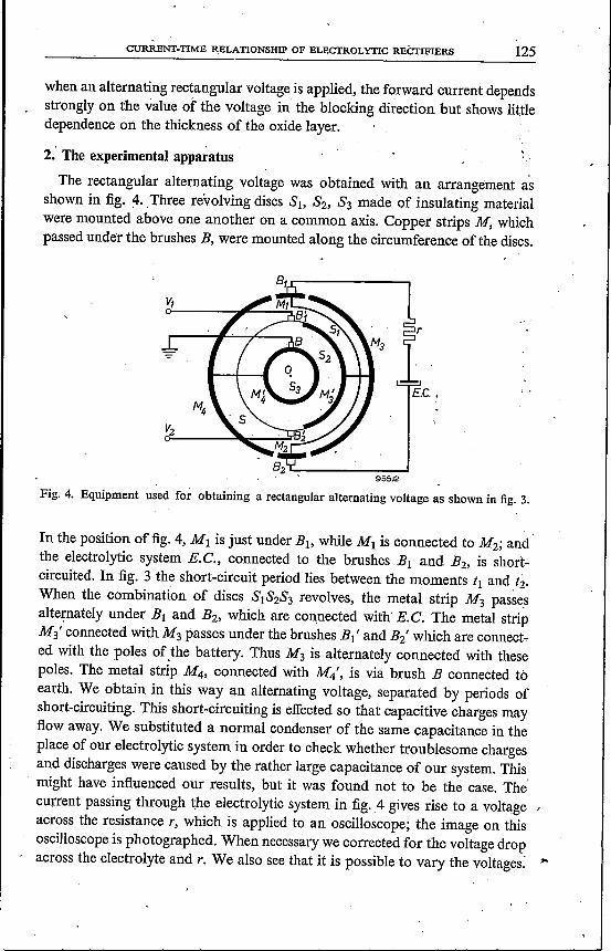
The rectangular alternating voltage was obtained with an arrangement asshown in fig. 4. ,Three revolving discs Sb S2, S3 made of insulating materialwere mounted above one another on a common axis. Copper strips M, whichpassed under the brushes B, were mounted along the circumference of the discs.
E.c.,
Fig. 4. Equipment used for obtaining a rectangular alternating voltage as shown in fig. 3.
In the position of fig. 4, M1 is just under Bb while M1 is connected to M2; andthe electrolytic system E.C., connected to the brushes B1 and B2' is short-circuited. In fig. 3 the short-circuit period lies between the moments t1 and ti.When the combination of discs SlS2S3 revolves, the metal strip M3 passe~alternately under B1 and B2' which are connected with' E.C. The metal stripM3' connected with M3 passes under the brushes B1' and B2' which are connect-ed with the poles ofthe battery. Thus M3 is alternately connected with thesepoles. The metal strip M4, connected with M4', is via brush B connected toearth. We obtain in this way an alternating voltage, separated by periods ofshort-circuiting. This short-circuiting is effected so that capacitive charges may:flowaway. We substituted a normal condenser of the same capacitance in theplace of our electrolytic system in order to check whether troublesome chargesand discharges were caused by the rather large capacitance of our system. Thismight have influenced our results, but it was found not to be the case. The'current passing through the electrolytic system in fig.4 gives rise to a voltage ,across the resistance r, which is applied to an oscilloscope; the image on thisoscilloscope is photographed. When necessary we corrected for the voltage dropacross the electrolyte and r, We also see that it is possible to vary the voltages: ,.
126 w. Ch. van GEEL and C. A. PISTORlUS
We generally used Al plates covered with an oxide layer 0·1 [Lthick and with asurface of 2 cm- the capacitance of which was about 0·1 [LF.The Al was of apurity of about 99·98 %; we used an aqueous solution of boric acid and borax.All experiments were carried out at room temperature.
3. Experiments
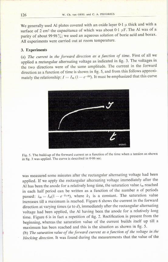
(a) The current in the forward direction as a function of time. First of all weapplied a rectangular alternating voltage as indicated in fig. 3. The voltages inthe two directions were of the same amplitude. The current in the forwarddirection as a function of time is shown in fig. 5, and from this follows approxi-mately the relationship: 1= Im (1- e-kt). Itmust be emphasized that this curve
t95510
Fig. 5. The build-up of the forward current as a function of the time when a tension as shownin fig. 3 was applied. The curve is described in 0·06 sec.
was measured some minutes after the rectangular alternating voltage had beenapplied. If we apply the rectangular alternating voltage immediately after theAl has been the anode for a relatively long time, the saturation value t-« reachedin each half period can be written as a function of the number n of periodspassed: im = Im(l - e-k1n), where k1 is a constant. The saturation valueincreases till a maximum is reached. Figure 6 shows the current in the forwarddirection at varying times (a to d), immediately after the rectangular alternatingvoltage had been applied, the Al having been the anode for a relatively longtime. Figure 6 is in fact a repetition of fig. 2. Rectification is present from thebeginning, whereas the saturation value of the current builds itself up till amaximum has been reached and this is the situation as shown in fig. 5.(b) The saturation value of the forward current as a function of the voltage in theblocking direction. It was found during the measurements that the value of the

CURRENT-TIME RELATIONSHIP OF ELECTROLYTIC RECTIFffiRS 1'27
saturation value Im of the foiward current was a function of the value of the\ .
voltage in the blocking direction. .
_g i~===", t
t
t
'----------_t95513
Fig. 6. The forward current as a function of the time when alternating rectangular voltage isapplied, at different moments (a, b, c, ti) after the Al has been a~ode for a relatively long time.
Figure 7 gives the saturation value Im of the forward current, when a voltageof 8·3 V was applied, as a function of the voltage in the blocking direction.At a blocking voltage of about 14 V the current in the forward direction hasonly a very small value. This proves that we cannot speak of a value of the for-ward current without taking into account the voltage in the blocking direction.In fig. 8 the logarithm of the saturation value of the forward current has beenplotted against the blocking voltage. We see that we may write:
Im = a exp (-bVs),
where Im is the forward current, Vs the blocking voltage, while a and bareconstants.(c) The dependence on theforward current upon the thickness of the layer. Analternating rectangular voltage of 12 V was applied to oxide layers of varyingthicknesses and the saturation value of the current was measured. The resultis shown in fig. 9. The value of the current did not change more than 20% for avariation in the thickness of the layer from 2.6.10-6 cm to 1.6.10-5 cm. Thevoltages, in the two directions had the same amplitude.

128 w. Ch. van GEEL and C. A. PJSTORIUS
100
1\\\\1\\1\'I'-I----
60
40
20
oo 8 12\{;(volts) 9699B
Fig. 7. The forward current as a function of the reverse voltage.
4
500
O.
,
0 \
~
.\1
5 .2
\
.1 1\30
~200E~ 100"'(,§~ 50
~
12
10
5
2
O.
o 0 2070--_ l's {volts} 969~9
Fig. 8. The logarithm of the forward current is plotted against the reverse voltage.

CURRENT-TIME RELATIONSHIP OF ELECTROLYTIC RECTIFIERS 129
The same result was obtained with alternating sinusoidal voltages. To passa current of 3·5 mAjcm2 through a layer of 5.10-6 cm, an alternating voltageof 7 V was necessary.For a layer about 6 times as thick, a voltage of 9·5 V had to be applied, which
is only 30% higher. So it appears that the relation between the current and theapplied voltage depends only little on the thickness of the layer.
<,i'<tl- r--
0
50
10 5 d (cm)97000
Fig. 9. The saturation value of the forward current when a rectangular voltage is applied, asa function of the thickness of the layer.
4. Conclusions
'First of all we shall consider the loop in the 1-V characteristic. In every halfperiod' of the alternating sinusoidal voltage there are two values of t for whichthe voltage has the same value. But as shown in fig. 5, at least in the part of thecurve where the saturation values have not yet been reached, the current I hasdifferent values for these two values of time, the value of I for the greater t beinglarger than for the smaller one. This means that the 1- V characteristic shows aloop. The fact that the loop also appears in the leakage current means that theI-t curve for the leakage current has the same shape as that shown in fig. 5. Thecharacter of these I-t curves is shown again in fig. 10. In fig. 1 both loops aredescribed in an anti-clockwise direction. It is difficult to explain the shape oftheI-t curves of figs 5 and 6. The difficulty is caused by the fact that there are ionicand electronic currents at the same time. We know that when a voltage is appliedin the forward direction a deformation ofthe layer takes place. This means thations have been displaced 3). The assumption can be made that in-this case Al+r+ions are displaced towards the AI, which ds the negative pole; and a spacecharge is formed. The residual voltages occurring prove that such a displacementhas happened 4). We assume that the potential distribution at the side of the Alis as givenin fig. 11.Here electrons can pass the potential barrier bycold emission.

,130 W. Ch. van GEEL and C. A. PISTORlUS
It might be possible that the width of this potential barrier will not dependgreatly upon the thickness of the oxide layer, which would explain qualitativelythe fact that the currënt is almost independent of the thickness of the layer.
I
t·
95517
Fig. 10. The shape of the current in both directions when a rectangular alternating voltage isapplied.
We can also explain the results shown in fig. 6 in a similar way. Initially thepotential barrier as shown in fig. 11 has a width nearly equal to the thicknessof the oxide layer, but this gradually decreases when the ions start accumulatingat the oxide-aluminium interface. At the same time more and more electronscan pass the potential barrier by cold emission.
-eV
Al-
95518
Fig.1!. The potential curve inside the layer at the side ofthe Al after the Al has been thenegativepole for some time.
CURRENT-TIME RELATIONSHIP OF ELECTROLYTIC RECTIFffiRS 131
The building-up of the barrier takes a few minutes. Diffusion causes a drift ofaluminium ions in the opposite direction and an equilibrium condition will beestablished. The current in this situátion is represented in fig. 5. As soon as areverse potential is supplied, Al+r+ ions are driven away from the AI oxideinterface to the oxide and at the next reversal ofthe potential (AI-) the barrierhasto be brought to its former shape, so that electrons can pass again.In this way we sèe that for higher reverse voltages it is more difficult to build
up a potential barrier with smaller width, so that less electrons can pass throughthe barrier. ..The authors are well aware ofthe fact that their discussion is onlya qualitative
one. They wish to thank Mr B. C. Bouma, who performed the first experimentshowing an I-t dependency in the forward direction. They are indebted toDr P. Winkel for discussions on the subject.
Eindhoven, October 1957
REFERENCES
1) A. J. Dekker and W. Ch. van Geel, Philips Res. Repts 5,303-314, 1950.2) W. Ch. van Geel and B. C. Bouma, Philips Res. Repts 5, 461-475, 1950.3) W. Ch. van Geel and B. C. Bouma, Philips Res. Repts 6, 401-424, 1951.4) W. Ch. van Geel and C. A. Pistorius, Philips Res. Repts 11, 471-478, 1956.


![Schottky Barrier Diode Module · Forward Voltage Drop VF[V] F Forward Current I [A] Performance Curves Fig. 1 : Typical Forward Voltage Drop vs. Instantaneous Forward Current Fig](https://img.pdfslide.us/doc/110x75/5edcd352ad6a402d6667aa87/schottky-barrier-diode-forward-voltage-drop-vfv-f-forward-current-i-a-performance.jpg)