Embed Size (px)
Citation preview
CurrentSensors &
Monitors
Low Voltage Products & Systems 8.11TRC 001 009 C0202
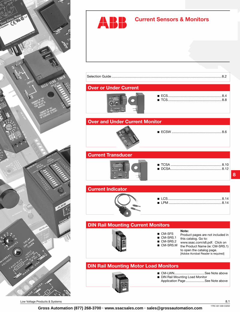
Over or Under Current
ECS ......................................................... 8.4 TCS ......................................................... 8.8
DIN Rail Mounting Current Monitors
CM-SFS CM-SRS.1 CM-SRS.2 CM-SRS.M
Current Transducer
TCSA ...................................................... 8.10 DCSA ...................................................... 8.12
LCS ......................................................... 8.14 LPM ........................................................ 8.14
Current Indicator
Over and Under Current Monitor
ECSW ..................................................... 8.6
Selection Guide .....................................................................................................................8.2
DIN Rail Mounting Motor Load Monitors
Current Sensors & Monitors
Note:Product pages are not included in this catalog. Go to: www.ssac.com/s8.pdf. Click on the Product Name (ie: CM-SRS.1) to open the catalog page. [Adobe Acrobat Reader is required]
CM-LWN ..................................See Note above DIN Rail Mounting Load Monitor
Application Page .....................See Note above
Gross Automation (877) 268-3700 · www.ssacsales.com · [email protected]
Current
Sensors &
Monitors
8.2 Low Voltage Products & Systems
1TRC 001 009 C0202
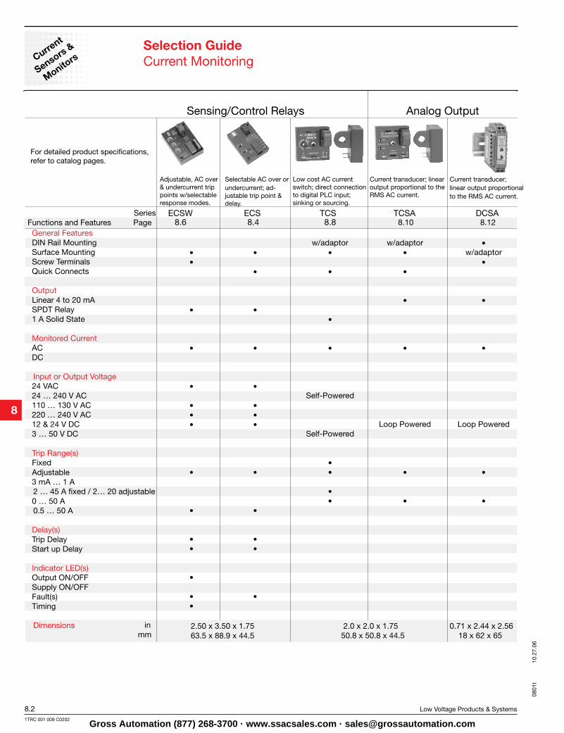
Selection GuideCurrent Monitoring
Sensing/Control Relays
General FeaturesDIN Rail MountingSurface MountingScrew TerminalsQuick Connects Output Linear 4 to 20 mASPDT Relay 1 A Solid State
Monitored Current AC DC Input or Output Voltage 24 VAC 24 … 240 V AC110 … 130 V AC220 … 240 V AC12 & 24 V DC 3 … 50 V DC
Trip Range(s) Fixed Adjustable 3 mA … 1 A 2 … 45 A fixed / 2… 20 adjustable0 … 50 A 0.5 … 50 A
Delay(s) Trip DelayStart up Delay Indicator LED(s) Output ON/OFFSupply ON/OFFFault(s) Timing Dimensions
Adjustable, AC over & undercurrent trip points w/selectable response modes.
Selectable AC over orundercurrent; ad-justable trip point & delay.
Low cost AC current switch; direct connection to digital PLC input; sinking or sourcing.
Series Functions and Features Page
ECSW ECS TCS TCSA DCSA8.6 8.4 8.8 8.10 8.12
w/adaptor w/adaptor • • • • • w/adaptor • • • • • • • • • • • • • • • • • Self-Powered • • • • • • Loop Powered Loop Powered Self-Powered • • • • • • • • • • • • • • • • • • • •
inmm
2.50 x 3.50 x 1.75 63.5 x 88.9 x 44.5
2.0 x 2.0 x 1.75 50.8 x 50.8 x 44.5
Current transducer; linear output proportional to the RMS AC current.
Analog Output
For detailed product specifications, refer to catalog pages.
Current transducer; linear output proportional to the RMS AC current.
0.71 x 2.44 x 2.5618 x 62 x 65
0801
t 10
.27.
06
Gross Automation (877) 268-3700 · www.ssacsales.com · [email protected]
CurrentSensors &
Monitors
Low Voltage Products & Systems 8.31TRC 001 009 C0202
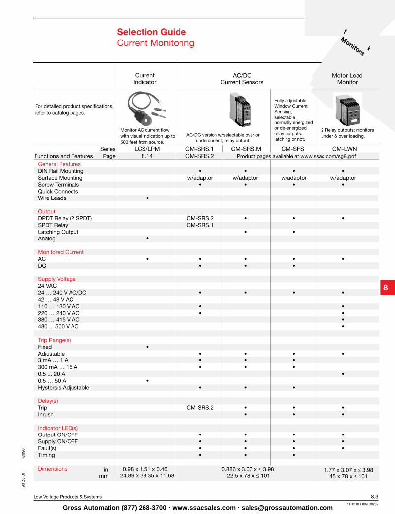
General FeaturesDIN Rail Mounting • • • •Surface Mounting w/adaptor w/adaptor w/adaptor w/adaptorScrew Terminals • • • •Quick Connects Wire Leads • Output DPDT Relay (2 SPDT) CM-SRS.2 • • •SPDT Relay CM-SRS.1 Latching Output • • Analog •
Monitored Current AC • • • • •DC • • • Supply Voltage24 VAC 24 … 240 V AC/DC • • • •42 … 48 V AC 110 … 130 V AC • •220 … 240 V AC • •380 … 415 V AC •480 ... 500 V AC • Trip Range(s) Fixed • Adjustable • • • •3 mA … 1 A • • • 300 mA … 15 A • • • 0.5 ... 20 A •0.5 … 50 A • Hystersis Adjustable • • • Delay(s)Trip CM-SRS.2 • • •Inrush • • •
Indicator LED(s) Output ON/OFF • • • •Supply ON/OFF • • • •Fault(s) • • • •Timing • • •
Dimensions
Selection GuideCurrent Monitoring
Monitor AC current flow with visual indication up to500 feet from source.
Series LCS/LPM CM-SRS.1 CM-SRS.M CM-SFS CM-LWNFunctions and Features Page 8.14 CM-SRS.2 Product pages available at www.ssac.com/sg8.pdf
inmm
0.98 x 1.51 x 0.46 24.89 x 38.35 x 11.68
AC/DC version w/selectable over or undercurrent; relay output.
Fully adjustable Window Current Sensing, selectable normally energized or de-energized relay outputs: latching or not.
0.886 x 3.07 x ≤ 3.98 22.5 x 78 x ≤ 101
1.77 x 3.07 x ≤ 3.9845 x 78 x ≤ 101
CurrentIndicator
Motor Load Monitor
AC/DC Current Sensors
For detailed product specifications, refer to catalog pages.
2 Relay outputs; monitors under & over loading.
0802t 10.27.06
Gross Automation (877) 268-3700 · www.ssacsales.com · [email protected]

Current
Sensors &
Monitors
8.4 Low Voltage Products & Systems
1TRC 001 009 C0202
Accessories
DescriptionThe ECS Series of Single Phase AC Current Sensors is a universal, overcurrent or undercurrent sensing control. Its built-in toroidal sensor eliminates the inconvenience of installing a stand-alone current transformer. Includes onboard adjustments for current sensing mode, trip point, and trip delay. Detects over or under current events like locked rotor, loss of load, an open heater or lamp load, or proves an operation is taking place or has ended.
OperationInput voltage must be supplied at all times for proper operation. When a fault is sensed throughout the trip delay, the output relay is energized. When the current returns to the normal run condition, the output and the delay are reset. If a fault is sensed and then corrected before the trip delay is completed, the relay will not energize and the trip delay is reset to zero.Adjustment Select the desired function, over or under current sensing. Set the trip point and trip delay to approximate settings. Apply power to the ECS and the monitored load. Turn adjustment and watch the LED. LED will light; turn slightly in opposite direction until LED is off. Adjustment can be done while connected to the control circuitry if the trip delay is set at maximum.
See accessory pages for specifications.
Toroidal Through Hole Wiring 0.5...50 A Trip Point Adjustable or Factory Fixed
Trip Delays 10 A SPDT Isolated Output
Contacts 5% Trip Point Hysteresis
(Dead Band)
Approvals:
Over/Under Current SensingECS SeriesCurrent Sensor
Connection
Example P/N:
Function
TP = Trip Point R = Reset OC = Monitored Current NO = Normally Open Contact NC = Normally Closed Contact A = Sensing Delay On Start Up TD = Trip Delay
Overcurrent
Undercurrent
Relay contacts are isolated.Dashed lines are internal connections.
–A - 0.150 ... 7 s–B - 0.5 ... 50 s
–0 - 0.5 ... 5 A –1 - 2 ... 20 A –H - 5 ... 50 A
Fixed -Specify 2 ... 50 Ain 1 A increments
–1 - 12 V DC–2 - 24 V AC–3 - 24 V DC–4 - 120 V AC–6 - 230 V AC
Input Trip Point Trip Delay Sensing Delay on Start up–F - Factory Fixed:
Adjustable Ranges Adjustable Ranges
Specify .08 ... 50 s
ECS41AC Fixed – ECSH610AD
–ECS -(selectable over or under current sensing)–ECSH -(overcurrent sensing)–ECSL - (undercurrent sensing)
XSeries
Female quick connect P/Ns:
P1015-13 (AWG 10/12)P1015-64 (AWG 14/16)P1015-14 (AWG 18/22)
V = Voltage I> = Overcurrent I< = Undercurrent W = Insulated Wire Carrying Monitored Current
Ordering Table
–Blank - 0 s–C - 1 s–D - 2 s–E - 3 s–F - 4 s–G - 5 s–H - 6 s
X X X X
EC
S02
B01
12
.28.
04
Gross Automation (877) 268-3700 · www.ssacsales.com · [email protected]
CurrentSensors &
Monitors
Low Voltage Products & Systems 8.51TRC 001 009 C0202
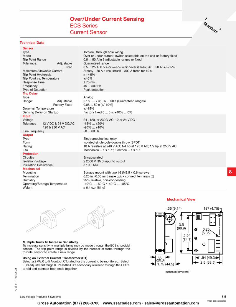
Technical Data
Over/Under Current SensingECS SeriesCurrent Sensor
Mechanical View
Inches (Millimeters)
Multiple Turns To Increase SensitivityTo increase sensitivity, multiple turns may be made through the ECS’s toroidal sensor. The trip point range is divided by the number of turns through the toroidal sensor to create a new range.
Using an External Current Transformer (CT)Select a 2 VA, 0 to 5 A output CT, rated for the current to be monitored. Select ECS adjustment range 0. Pass the CT’s secondary wire lead through the ECS’s toroid and connect both ends together.
SensorType Toroidal, through hole wiring Mode Over or under current, switch selectable on the unit or factory fixedTrip Point Range 0.5 ... 50 A in 3 adjustable ranges or fixedTolerance: Adjustable Guaranteed range Fixed 0.5 ... 25 A: 0.5 A or +/-5% whichever is less; 26 ... 50 A: +/-2.5%Maximum Allowable Current Steady – 50 A turns; Inrush – 300 A turns for 10 sTrip Point Hysteresis ≅+/-5%Trip Point vs. Temperature +/-5%Response Time ≤ 75 msFrequency 45 ... 500 HzType of Detection Peak detectionTrip DelayType AnalogRange: Adjustable 0.150 ... 7 s; 0.5 ... 50 s (Guaranteed ranges) Factory Fixed 0.08 ... 50 s (+/-10%)Delay vs. Temperature +/-15%Sensing Delay on Startup Factory fixed 0 ... 6 s: +40% ... 0%InputVoltage 24 , 120, or 230 V AC; 12 or 24 V DCTolerance 12 V DC & 24 V DC/AC -15% ... +20% 120 & 230 V AC -20% ... +10% Line Frequency 50 ... 60 HzOutputType Electromechanical relayForm Isolated single pole double throw (SPDT)Rating 10 A resistive at 240 V AC; 1/4 hp at 125 V AC; 1/2 hp at 250 V ACLife Mechanical – 1 x 10⁶ ; Electrical – 1 x 10⁵
ProtectionCircuitry EncapsulatedIsolation Voltage ≥ 2500 V RMS input to outputInsulation Resistance ≥ 100 MΩ MechanicalMounting Surface mount with two #6 (M3.5 x 0.6) screwsTermination 0.25 in. (6.35 mm) male quick connect terminals (5)Humidity 95% relative, non-condensingOperating/Storage Temperature -40°C ... +60°C / -40°C ... +85°CWeight ≅ 6.4 oz (181 g)
EC
S02B
01 12.28.04
Gross Automation (877) 268-3700 · www.ssacsales.com · [email protected]
Current
Sensors &
Monitors
8.6 Low Voltage Products & Systems
1TRC 001 009 C0202
Description
OperationWhen the input voltage is applied, sensing delay on startup begins and the output transfers (if normally energized is selected). Upon completion of the startup delay, sensing of the monitored current begins. As long as current is above undercurrent trip point and below the overcurrent trip point (inside the window), the output relay remains in its normal operating condition and both red LED’s are OFF. The green LED glows when the output is energized. If current varies outside the window, the associated red LED glows, and the trip delay begins. If the current remains outside the window for the full trip delay, the relay transfers to fault condition state. If the current returns to normal levels (inside the window) during the trip delay, the red LED goes OFF, the trip delay is reset, and the output remains in the normal condition.Reset: Remove input voltage or open latch switch. If zero current detection is selected, the unit will reset as soon as zero current is detected.Operation With Zero Current Detection Enabled: If the current decreases to zero within the trip delay period, then zero current is viewed as an acceptable current level. The unit’s output remains in its normal operating state. This allows the monitored load to cycle ON and OFF without nuisance tripping the ECSW. Zero current is defined as current flow of less than 250 milliamp-turns. Note: When zero current detect is selected, the latching operation of switch SW2 is canceled; the output will not latch after a fault trip.
Notes on Operation: 1) There is no hysteresis on the trip points. The overcurrent and undercurrent trip points should be adjusted to provide adequate protection against short cycling. 2) If the upper set point is set below the lower set point, both red LED’s will glow indicating a setting error.3) If zero current detection is selected (SW2 ON), and the system is wired to disconnect the monitored load, the system may short cycle. After the unit trips, the load de-energizes, and zero current is detected. The ECSW resets, and the load energizes again immediately and may be short cycled. 4) The sensing delay on start up only occurs when input voltage is applied. When zero current detection is selected, the trip delay must be longer than the duration of the inrush current or the unit will trip on the inrush current.
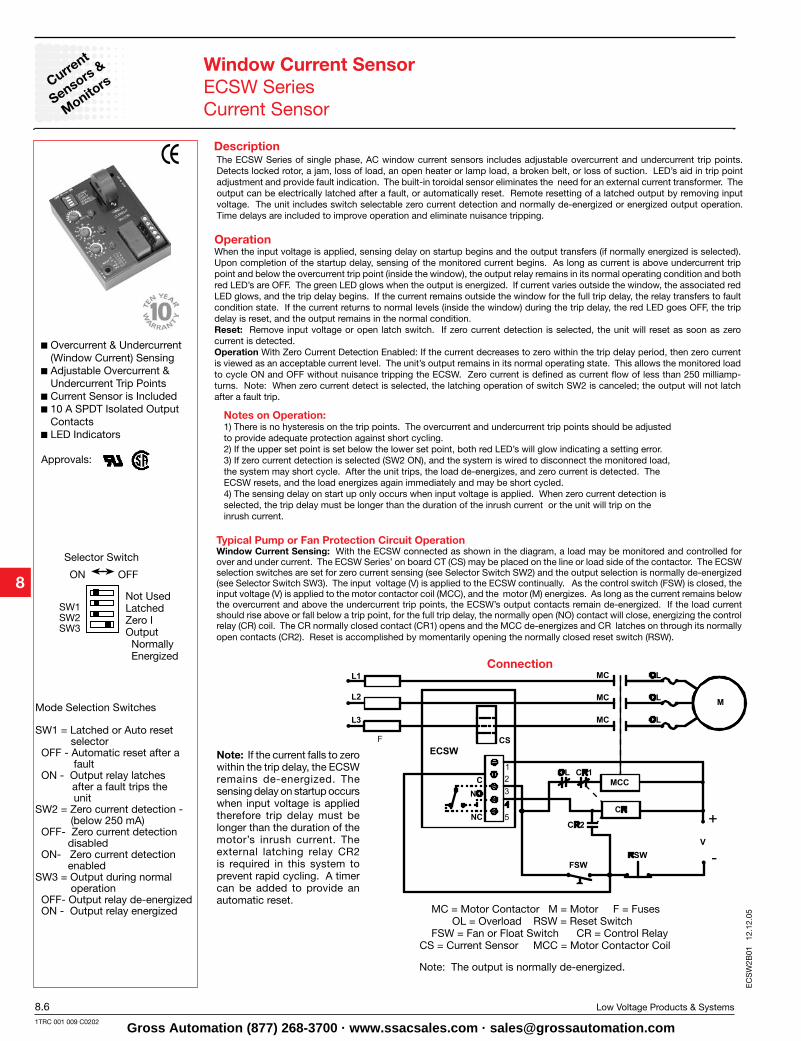
Overcurrent & Undercurrent (Window Current) Sensing
Adjustable Overcurrent & Undercurrent Trip Points
Current Sensor is Included 10 A SPDT Isolated Output
Contacts LED Indicators
Approvals:
Window Current SensorECSW SeriesCurrent Sensor
Connection
Not UsedLatchedZero IOutput Normally Energized
ON OFF
Selector Switch
SW1SW2SW3
Mode Selection Switches
SW1 = Latched or Auto reset selector OFF - Automatic reset after a fault ON - Output relay latches after a fault trips the unit SW2 = Zero current detection - (below 250 mA) OFF- Zero current detection disabled ON- Zero current detection enabled SW3 = Output during normal operation OFF- Output relay de-energized ON - Output relay energized
The ECSW Series of single phase, AC window current sensors includes adjustable overcurrent and undercurrent trip points. Detects locked rotor, a jam, loss of load, an open heater or lamp load, a broken belt, or loss of suction. LED’s aid in trip point adjustment and provide fault indication. The built-in toroidal sensor eliminates the need for an external current transformer. The output can be electrically latched after a fault, or automatically reset. Remote resetting of a latched output by removing input voltage. The unit includes switch selectable zero current detection and normally de-energized or energized output operation. Time delays are included to improve operation and eliminate nuisance tripping.
Typical Pump or Fan Protection Circuit Operation Window Current Sensing: With the ECSW connected as shown in the diagram, a load may be monitored and controlled for over and under current. The ECSW Series’ on board CT (CS) may be placed on the line or load side of the contactor. The ECSW selection switches are set for zero current sensing (see Selector Switch SW2) and the output selection is normally de-energized (see Selector Switch SW3). The input voltage (V) is applied to the ECSW continually. As the control switch (FSW) is closed, the input voltage (V) is applied to the motor contactor coil (MCC), and the motor (M) energizes. As long as the current remains below the overcurrent and above the undercurrent trip points, the ECSW’s output contacts remain de-energized. If the load current should rise above or fall below a trip point, for the full trip delay, the normally open (NO) contact will close, energizing the control relay (CR) coil. The CR normally closed contact (CR1) opens and the MCC de-energizes and CR latches on through its normally open contacts (CR2). Reset is accomplished by momentarily opening the normally closed reset switch (RSW).
Note: If the current falls to zero within the trip delay, the ECSW remains de-energized. The sensing delay on startup occurs when input voltage is applied therefore trip delay must be longer than the duration of the motor’s inrush current. The external latching relay CR2 is required in this system to prevent rapid cycling. A timer can be added to provide an automatic reset.
MC = Motor Contactor M = Motor F = Fuses OL = Overload RSW = Reset Switch FSW = Fan or Float Switch CR = Control Relay CS = Current Sensor MCC = Motor Contactor Coil
Note: The output is normally de-energized.
EC
SW
2B01
12
.12.
05
Gross Automation (877) 268-3700 · www.ssacsales.com · [email protected]
CurrentSensors &
Monitors
Low Voltage Products & Systems 8.71TRC 001 009 C0202
Technical Data
Window Current SensorECSW SeriesCurrent Sensor
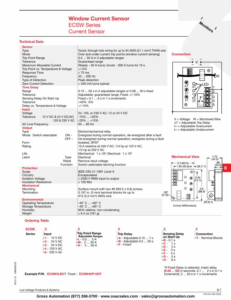
–A - Adjustable 0.15 ... 7 s–B - Adjustable 0.5 ... 50 s–F - Fixed*
Series Input Trip Delay Sensing Delay on Start Up
ConnectionTrip Point RangeAdjustable Ranges –T - Terminal Blocks–1 - 12 V DC
–2 - 24 V AC–3 - 24 V DC–4 - 120 V AC–6 - 230 V AC
–L - 0.5 ... 5 A–M - 2 ... 20 A–H - 5 ... 50 A
X ECSW
–B - 0.1 s–C - 1 s–D - 2 s–E - 3 s–F - 4 s–G - 5 s–H - 6 s
*If Fixed Delay is selected, insert delay [0.08 ... 50] in seconds. 0.1 ... 2 s in 0.1 s increments; 2 ... 50 s in 1 s incrementsExample P/N: ECSW4LBCT Fixed - ECSW4HF10DT
Ordering Table
Mechanical View
Inches (Millimeters)
Connection
SensorType Toroid, through hole wiring for up to #4 AWG (21.1 mm2) THHN wireMode Over and under current trip points (window current sensing)Trip Point Range 0.5 ... 50 A in 3 adjustable ranges Tolerance Guaranteed rangeMaximum Allowable Current Steady - 50 A turns; Inrush - 300 A turns for 10 sTrip Point vs. Temperature & Voltage +/-5%Response Time ≤ 75 msFrequency 45 ... 500 HzType of Detection Peak detectionZero Current Detection < 250 mA turns typicalTime DelayRange 0.15 ... 50 s in 2 adjustable ranges or 0.08 ... 50 s fixed Tolerance Adjustable: guaranteed range; Fixed: +/-10%Sensing Delay On Start Up Fixed ≅ 0.1 ... 6 s in 1 s incrementsTolerance +40% -0%Delay vs. Temperature & Voltage +/-15%InputVoltage 24, 120, or 230 V AC; 12 or 24 V DCTolerance 12 V DC & 24 V DC/AC -15% ... +20% 120 & 230 V AC -20% ... +10%AC Line Frequency 50 ... 60 HzOutputType Electromechanical relayMode: Switch selectable ON - Energized during normal operation, de-energized after a fault OFF - De-energized during normal operation, energizes during a faultForm Isolated, SPDTRating 10 A resistive at 240 V AC; 1/4 hp at 125 V AC; 1/2 hp at 250 V ACLife Mechanical: 1 x 10⁶; Electrical: 1 x 10⁵
Latch Type Electrical Reset Remove input voltage Function Switch selectable latching functionProtectionSurge IEEE C62.41-1991 Level ACircuitry EncapsulatedIsolation Voltage ≥ 2500 V RMS input to outputInsulation Resistance ≥ 100 MΩ MechanicalMounting Surface mount with two #6 (M3.5 x 0.6) screwsTermination 0.197 in. (5 mm) terminal blocks for up to #12 (3.2 mm2) AWG wireEnvironmentalOperating Temperature -40° C ... +60° CStorage Temperature -40° C ... +85° CHumidity 95% relative, non-condensingWeight ≅ 6.4 oz (181 g)
V = Voltage W = Monitored Wire∆T = Adjustable Trip Delay I> = Adjustable Overcurrent I< = Adjustable Undercurrent
X X X X
EC
SW
2B01
12.12.05
Gross Automation (877) 268-3700 · www.ssacsales.com · [email protected]
Current
Sensors &
Monitors
8.8 Low Voltage Products & Systems
1TRC 001 009 C0202
TCS X X X
Accessories
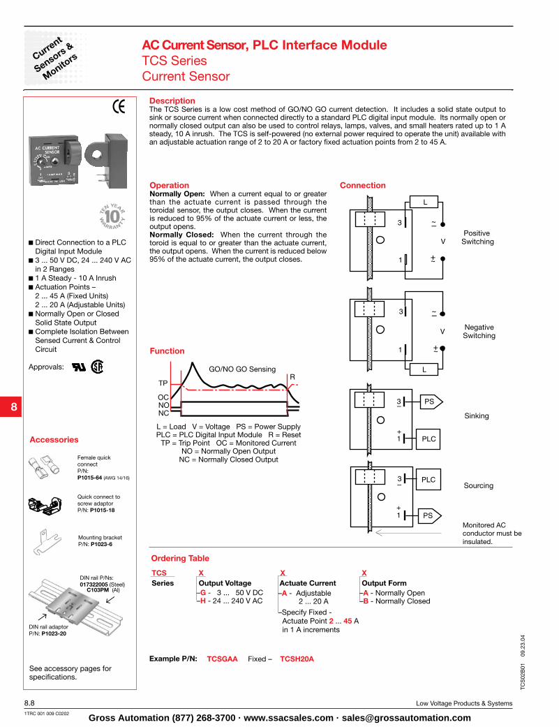
DescriptionThe TCS Series is a low cost method of GO/NO GO current detection. It includes a solid state output to sink or source current when connected directly to a standard PLC digital input module. Its normally open or normally closed output can also be used to control relays, lamps, valves, and small heaters rated up to 1 A steady, 10 A inrush. The TCS is self-powered (no external power required to operate the unit) available with an adjustable actuation range of 2 to 20 A or factory fixed actuation points from 2 to 45 A.
Operation Normally Open: When a current equal to or greater than the actuate current is passed through the toroidal sensor, the output closes. When the current is reduced to 95% of the actuate current or less, the output opens.Normally Closed: When the current through the toroid is equal to or greater than the actuate current, the output opens. When the current is reduced below 95% of the actuate current, the output closes.
See accessory pages for specifications.
Direct Connection to a PLC Digital Input Module
3 ... 50 V DC, 24 ... 240 V AC in 2 Ranges
1 A Steady - 10 A Inrush Actuation Points –
2 ... 45 A (Fixed Units) 2 ... 20 A (Adjustable Units)
Normally Open or Closed Solid State Output
Complete Isolation Between Sensed Current & Control Circuit
Approvals:
AC Current Sensor, PLC Interface ModuleTCS SeriesCurrent Sensor
Connection
Example P/N:
Function
L = Load V = Voltage PS = Power SupplyPLC = PLC Digital Input Module R = Reset
TP = Trip Point OC = Monitored Current NO = Normally Open Output
NC = Normally Closed Output
GO/NO GO Sensing
Positive Switching
Negative Switching
Sinking
Sourcing
Monitored AC conductor must beinsulated.
Female quick connect P/N: P1015-64 (AWG 14/16)
Quick connect toscrew adaptorP/N: P1015-18
Mounting bracketP/N: P1023-6
DIN rail P/Ns:017322005 (Steel)
DIN rail adaptorP/N: P1023-20
→←
C103PM (Al)Series
–Specify Fixed - Actuate Point 2 ... 45 A in 1 A increments
Output Voltage Actuate Current Output Form–G - 3 ... 50 V DC–H - 24 ... 240 V AC
–A - Adjustable 2 ... 20 A
–A - Normally Open–B - Normally Closed
TCSGAA Fixed – TCSH20A
Ordering Table
TCS
02B
01
09.2
3.04
Gross Automation (877) 268-3700 · www.ssacsales.com · [email protected]
CurrentSensors &
Monitors
Low Voltage Products & Systems 8.91TRC 001 009 C0202
Technical Data
AC Current Sensor, PLC Interface ModuleTCS SeriesCurrent Sensor
Mechanical View
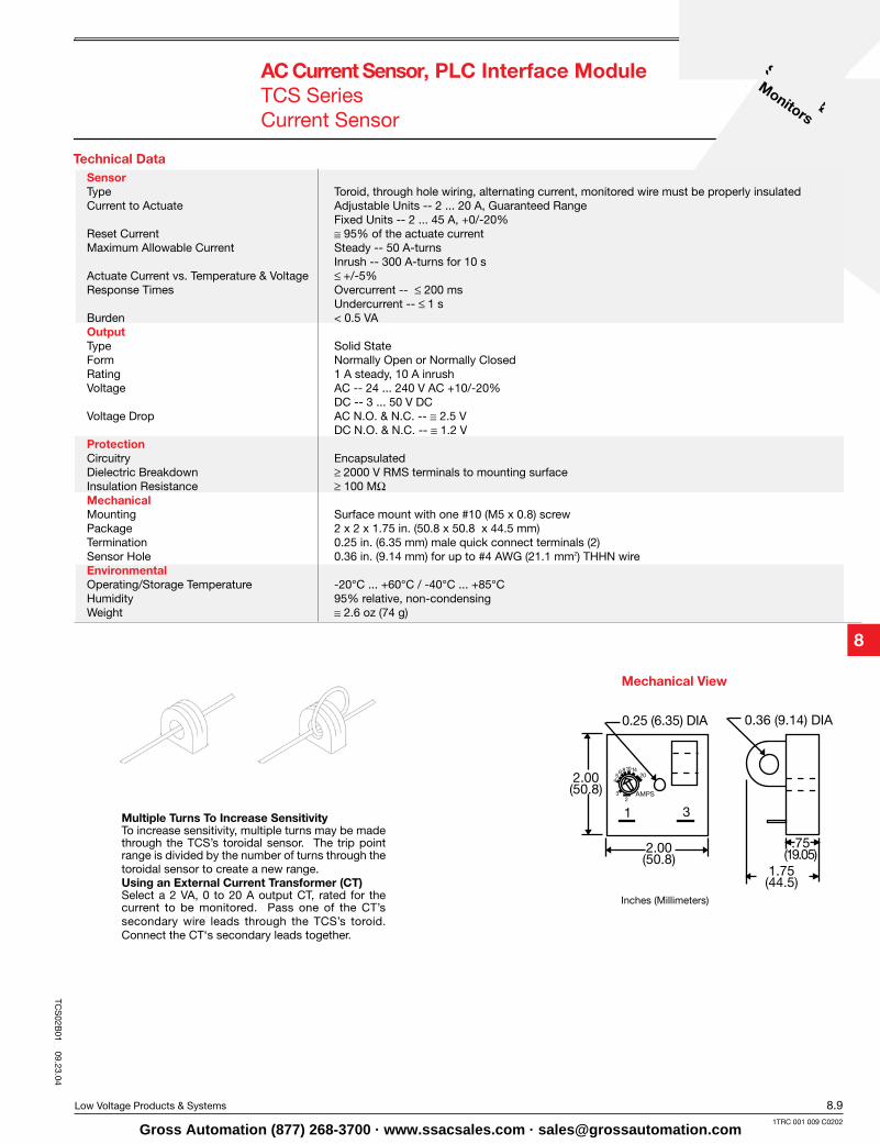
Multiple Turns To Increase SensitivityTo increase sensitivity, multiple turns may be made through the TCS’s toroidal sensor. The trip point range is divided by the number of turns through the toroidal sensor to create a new range. Using an External Current Transformer (CT)Select a 2 VA, 0 to 20 A output CT, rated for the current to be monitored. Pass one of the CT’s secondary wire leads through the TCS’s toroid. Connect the CT‘s secondary leads together.
Inches (Millimeters)
SensorType Toroid, through hole wiring, alternating current, monitored wire must be properly insulatedCurrent to Actuate Adjustable Units -- 2 ... 20 A, Guaranteed Range Fixed Units -- 2 ... 45 A, +0/-20%Reset Current ≅ 95% of the actuate currentMaximum Allowable Current Steady -- 50 A-turns Inrush -- 300 A-turns for 10 sActuate Current vs. Temperature & Voltage ≤+/-5%Response Times Overcurrent -- ≤ 200 ms Undercurrent -- ≤1 sBurden < 0.5 VAOutputType Solid StateForm Normally Open or Normally ClosedRating 1 A steady, 10 A inrushVoltage AC -- 24 ... 240 V AC +10/-20% DC -- 3 ... 50 V DCVoltage Drop AC N.O. & N.C. -- ≅ 2.5 V DC N.O. & N.C. -- ≅ 1.2 VProtectionCircuitry EncapsulatedDielectric Breakdown ≥2000 V RMS terminals to mounting surfaceInsulation Resistance ≥ 100 MΩ MechanicalMounting Surface mount with one #10 (M5 x 0.8) screwPackage 2 x 2 x 1.75 in. (50.8 x 50.8 x 44.5 mm)Termination 0.25 in. (6.35 mm) male quick connect terminals (2)Sensor Hole 0.36 in. (9.14 mm) for up to #4 AWG (21.1 mm2) THHN wireEnvironmental Operating/Storage Temperature -20°C ... +60°C / -40°C ... +85°CHumidity 95% relative, non-condensingWeight ≅ 2.6 oz (74 g)
TCS
02B01
09.23.04
Gross Automation (877) 268-3700 · www.ssacsales.com · [email protected]
Current
Sensors &
Monitors
8.10 Low Voltage Products & Systems
1TRC 001 009 C0202
Accessories
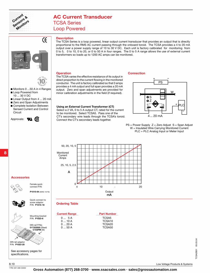
DescriptionThe TCSA Series is a loop powered, linear output current transducer that provides an output that is directly proportional to the RMS AC current passing through the onboard toroid. The TCSA provides a 4 to 20 mA output over a power supply range of 10 to 30 V DC. Each unit is factory calibrated for monitoring from 0 to 5, 0 to 10, 0 to 20, or 0 to 50 A in four ranges. The 0 to 5 A range allows the use of external current transformers so loads up to 1200 AC amps can be monitored.
OperationThe TCSA varies the effective resistance of its output in direct proportion to the current flowing in the monitored conductor. The unit is factory calibrated so that 0 amps provides a 4 mA output and full span provides a 20 mA output. Zero and span adjustments are provided for minor calibration adjustments in the field (if required).
See accessory pages for specifications.
Monitors 0 ...50 A in 4 Ranges Loop Powered from
10 ... 30 V DC Linear Output from 4 ... 20 mA Zero and Span Adjustments Complete Isolation Between
Sensed Current and Control Circuit
Approvals:
AC Current TransducerTCSA SeriesLoop Powered
Connection
Quick connect toscrew adaptorP/N: P1015-18
Female quickconnect P/N:
P1015-64 (AWG 14/16)
Mounting bracketP/N: P1023-6
DIN rail P/Ns:017322005 (Steel)
DIN rail adaptorP/N: P1023-20
→←
C103PM (Al)
PS
PS = Power Supply Z = Zero Adjust S = Span Adjust W = Insulated Wire Carrying Monitored Current
PLC = PLC Analog Input or Meter Input
0 ... 5 A0 ... 10 A0 ... 20 A0 ... 50 A
TCSA5 TCSA10 TCSA20 TCSA50
Part NumberCurrent Range
4 10 20
mA
A
50, 20, 10, 5
25, 10, 5, 2.5
0
MonitoredCurrentAmps
Output
Using an External Current Transformer (CT)Select a 2 VA, 0 to 5 A output CT, rated for the currentto be monitored. Select TCSA5. Pass one of the CT’s secondary wire leads through the TCSA’s toroid. Connect the CT’s secondary leads together.
Ordering Table
TCS
A2B
01
05.0
3.04
Gross Automation (877) 268-3700 · www.ssacsales.com · [email protected]

CurrentSensors &
Monitors
Low Voltage Products & Systems 8.111TRC 001 009 C0202
Technical Data
AC Current TransducerTCSA SeriesLoop Powered
Mechanical View
Inches (Millimeters)
*Minimum loop power supply voltage equals the minimum sensor voltage 10 V DC plus the voltage drop developed across all the other loop devices at 20 mA.
SensorType Toroid, through hole wiring, alternating current (Monitored conductor must be properly insulated)Monitored AC Current 0 ... 50 ARanges 4 factory calibrated ranges 0 ... 5A, 0 ... 10A, 0 ... 20A, or 0 ... 50A Factory Calibration +/-0.5% of full scaleMaximum Allowable Current Steady – 50 A turns Inrush – 300 A turns for 10 sRepeat Accuracy +/-0.25% of full scale under fixed conditionsResponse Time ≅ 300 msBurden ≤ 0.5 VAFrequency 0 ... 20A / 21 ... 50A 20 ... 100 Hz / 30 ... 100 HzTemperature Coefficient +/-0.05%/°COutput Type: Series Connection Current directly proportional to monitored currentRange 4 ... 20 mASensor Supply Voltage* 10 ... 30 V DCMomentary Voltage 40 V DC for 1 mZero Adjust ≅ 3.75 ... 4.25 mASpan Adjust 18 mA ... 22 mAAdjustment Mini-screw, 25 turn potentiometerProtection Dielectric Breakdown ≥ 2000 V RMS terminals to mounting surfaceInsulation Resistance ≥ 100 MΩ Polarity Units are reverse polarity protectedMechanicalMounting Surface mount with one #10 (M5 x 0.8) screwPackage 2 x 2 x 1.75 in. (50.8 x 50.8 x 44.5 mm)Termination 0.25 in. (6.35 mm) male quick connect terminalsSensor Hole 0.36 in. (9.14 mm) for up to #4 AWG (21.1 mm2) THHN wireEnvironmentalOperating Temperature -30°C ... +60°CStorage Temperature -40°C ... +85°CHumidity 95% relative, non-condensingWeight ≅ 2.4 oz (68 g)
TCS
A2B
01 05.03.04
Gross Automation (877) 268-3700 · www.ssacsales.com · [email protected]
Current
Sensors &
Monitors
8.12 Low Voltage Products & Systems
1TRC 001 009 C0202
Accessories
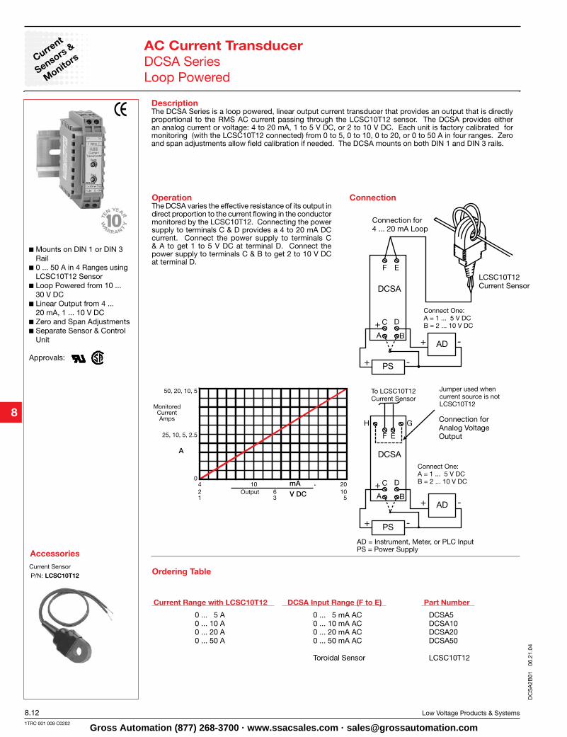
DescriptionThe DCSA Series is a loop powered, linear output current transducer that provides an output that is directly proportional to the RMS AC current passing through the LCSC10T12 sensor. The DCSA provides either an analog current or voltage: 4 to 20 mA, 1 to 5 V DC, or 2 to 10 V DC. Each unit is factory calibrated for monitoring (with the LCSC10T12 connected) from 0 to 5, 0 to 10, 0 to 20, or 0 to 50 A in four ranges. Zero and span adjustments allow field calibration if needed. The DCSA mounts on both DIN 1 and DIN 3 rails.
OperationThe DCSA varies the effective resistance of its output in direct proportion to the current flowing in the conductor monitored by the LCSC10T12. Connecting the power supply to terminals C & D provides a 4 to 20 mA DC current. Connect the power supply to terminals C & A to get 1 to 5 V DC at terminal D. Connect the power supply to terminals C & B to get 2 to 10 V DC at terminal D.
Mounts on DIN 1 or DIN 3 Rail
0 ... 50 A in 4 Ranges using LCSC10T12 Sensor
Loop Powered from 10 ... 30 V DC
Linear Output from 4 ... 20 mA, 1 ... 10 V DC
Zero and Span Adjustments Separate Sensor & Control
Unit
Approvals:
AC Current TransducerDCSA SeriesLoop Powered
Connection
Current Sensor
P/N: LCSC10T12
AD = Instrument, Meter, or PLC Input PS = Power Supply
Connection for 4 ... 20 mA Loop
LCSC10T12Current Sensor
To LCSC10T12Current Sensor
Connection forAnalog VoltageOutput
Connect One: A = 1 ... 5 V DCB = 2 ... 10 V DC
Connect One: A = 1 ... 5 V DCB = 2 ... 10 V DC
Jumper used whencurrent source is notLCSC10T12
Part NumberDCSA Input Range (F to E)Current Range with LCSC10T12
DCSA5 DCSA10 DCSA20 DCSA50
LCSC10T12
0 ... 5 mA AC0 ... 10 mA AC0 ... 20 mA AC0 ... 50 mA AC
Toroidal Sensor
0 ... 5 A0 ... 10 A0 ... 20 A0 ... 50 A
4 10 20mA
A
50, 20, 10, 5
25, 10, 5, 2.5
0
MonitoredCurrentAmps
21
63
10 5V DC Output
Ordering Table
DC
SA
2B01
06
.21.
04
Gross Automation (877) 268-3700 · www.ssacsales.com · [email protected]
CurrentSensors &
Monitors
Low Voltage Products & Systems 8.131TRC 001 009 C0202
Technical Data
AC Current TransducerDCSA SeriesLoop Powered
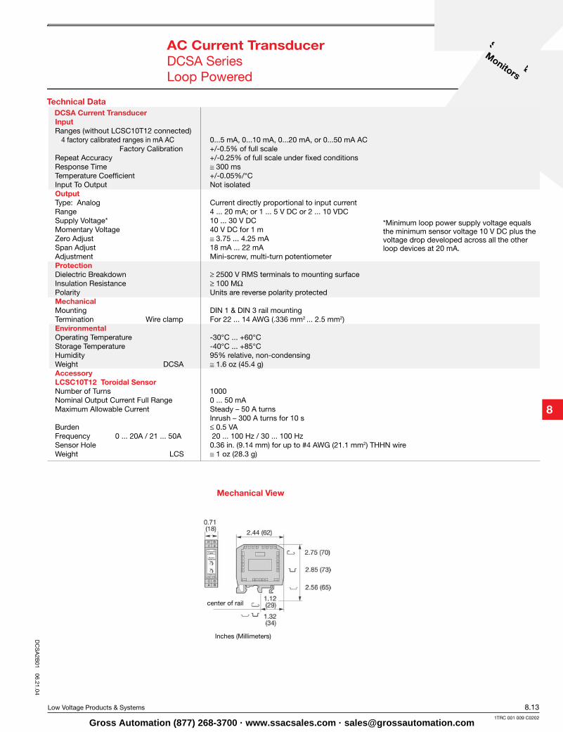
Mechanical View
Inches (Millimeters)
*Minimum loop power supply voltage equals the minimum sensor voltage 10 V DC plus the voltage drop developed across all the other loop devices at 20 mA.
center of rail
DCSA Current Transducer InputRanges (without LCSC10T12 connected) 4 factory calibrated ranges in mA AC 0...5 mA, 0...10 mA, 0...20 mA, or 0...50 mA AC Factory Calibration +/-0.5% of full scaleRepeat Accuracy +/-0.25% of full scale under fixed conditionsResponse Time ≅ 300 msTemperature Coefficient +/-0.05%/°CInput To Output Not isolatedOutput Type: Analog Current directly proportional to input currentRange 4 ... 20 mA; or 1 ... 5 V DC or 2 ... 10 VDCSupply Voltage* 10 ... 30 V DCMomentary Voltage 40 V DC for 1 mZero Adjust ≅ 3.75 ... 4.25 mASpan Adjust 18 mA ... 22 mAAdjustment Mini-screw, multi-turn potentiometerProtection Dielectric Breakdown ≥ 2500 V RMS terminals to mounting surfaceInsulation Resistance ≥ 100 MΩ Polarity Units are reverse polarity protectedMechanicalMounting DIN 1 & DIN 3 rail mountingTermination Wire clamp For 22 ... 14 AWG (.336 mm2 ... 2.5 mm2)EnvironmentalOperating Temperature -30°C ... +60°CStorage Temperature -40°C ... +85°CHumidity 95% relative, non-condensingWeight DCSA ≅ 1.6 oz (45.4 g)Accessory LCSC10T12 Toroidal SensorNumber of Turns 1000Nominal Output Current Full Range 0 ... 50 mAMaximum Allowable Current Steady – 50 A turns Inrush – 300 A turns for 10 sBurden ≤ 0.5 VAFrequency 0 ... 20A / 21 ... 50A 20 ... 100 Hz / 30 ... 100 HzSensor Hole 0.36 in. (9.14 mm) for up to #4 AWG (21.1 mm2) THHN wireWeight LCS ≅ 1 oz (28.3 g)
DC
SA
2B01
06.21.04
Gross Automation (877) 268-3700 · www.ssacsales.com · [email protected]
Current
Sensors &
Monitors
8.14 Low Voltage Products & Systems
1TRC 001 009 C0202
CURRENT LIMITINGRESISTOR
12 ± 1(304.8 ± 25.4)
STRIPPED 0.25 (6.35)0.53
(13.46)
0.28(7.11)
0.22(5.59)
UL100724 AWG (0.25 mm2 ) <_
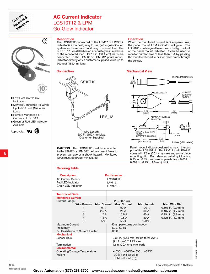
DescriptionThe LCS10T12 connected to the LPM12 or LPMG12 indicator is a low cost, easy to use, go/no go indication system for the remote monitoring of current flow. The LCS10T12 is installed on an adequately insulated wire of the monitored load. Its 12 in. (30.4 cm) leads are connected to the LPM12 or LPMG12 panel mount indicator directly or via customer supplied wires up to 500 feet (152.4 m) long.
OperationWhen the monitored current is 5 ampere-turns, the panel mount LPM indicator will glow. The LCS10T12 is designed to maximize the light output of the panel mount indicator. It can be used to monitor current flow of less than 5 A by passing the monitored conductor 2 or more times through the sensor.
Mechanical View
Low Cost Go/No Go Indication
May Be Connected To Wires Up To 500 Feet (152.4 m) Long
Remote Monitoring of Currents Up To 50 A
Green or Red LED Indicator Available
Approvals:
AC Current IndicatorLCS10T12 & LPMGo-Glow Indicator
Connection
Wire Length: 500 Ft. (152.4 m) Max.(Customer Supplied)
CAUTION: The LCS10T12 must be connected to the LPM12 or LPMG12 before current flows to prevent damage or a shock hazard. Monitored wires must be properly insulated.
Part NumberDescriptionAC Current SensorRed LED IndicatorGreen LED Indicator
LCS10T12 LPM12 LPMG12
Inches (Millimeters)
Panel mount indicator designed to match the out-put of the LCS10T12. The LPM12 and LPMG12 come with 12 in. (30.4 cm) wires and a one piece mounting clip. Both devices install quickly in a 0.25 in. (6.35 mm) hole in panels from 0.031 ... 0.062 in. (0.79 ... 1.6 mm) thick.
Inches (Millimeters)
Monitored Current
Mechanical
Environmental
Technical Data
Ordering Table
Current Range 2 ... 50 A AC Wire Passes Min. Current Max. Current Max. Inrush Max. Wire Dia. 1 5 A 50 A 120 A 0.355 in. (9.0 mm) 2 2.5 A 25 A 60 A 0.187 in. (4.7 mm) 3 1.7 A 16.6 A 40 A 0.15 in. (3.8 mm) 4 1.3 A 12.5 A 30 A 0.125 in. (3.2 mm) 5 5/X 50/X 120/X Maximum Current 50 ampere-turns continuousFrequency 50 ... 60 Hz DC Resistance of Current Limiter 65 Ω
Sensor Hole 0.36 in. (9.14 mm) for up to #4 AWG (21.1 mm2) THHN wire Termination 12 in. (30.4 cm) wire leads
Operating/Storage Temperature -40°C ... +60°C/-40°C ... +85°CWeight LCS: ≅ 0.8 oz (23 g) LPM: ≅ 0.2 oz (6 g) LC
S01
B01
05
.03.
04
Gross Automation (877) 268-3700 · www.ssacsales.com · [email protected]