Embed Size (px)
Citation preview
Final 5/12/14
MuCool Test Area (MTA) Experimental CapabilitiesMarch 2014
This document outlines beam properties and facilities infrastructure available for experimenters wishing to utilize the MuCool Test Area for small scale/short duration experiments.
Final 5/12/14
Table of Contents1 Current MTA Capabilities – Beamline and Experimental Hall...............................................3
1.1 Description of Current Facility.........................................................................................31.2 Overview of Beamline and Hall Operation.......................................................................31.3 Beam Parameters...............................................................................................................51.4 Experimental Possibilities Consistent with Current RF Activities...................................61.5 Detector Support...............................................................................................................81.6 Process for Approving Experimental Tests at MTA.......................................................11
2 Capabilities inconsistent with concurrent RF activities.........................................................11
Final 5/12/14
1 Current MTA Capabilities – Beamline and Experimental Hall
1.1 Description of Current FacilityAn experimental area designed to develop, test, and verify muon ionization cooling apparatus using the 400-MeV Fermilab Linac proton beam, the MuCool Test Area (MTA), is shown Figure 1Error: Reference source not found. The purpose of the facility is to support a program of testing basic techniques and components proposed for muon ionization cooling in a proton beam judged equivalent in impact to a muon beam. This research program, referred to as “MuCool”, could provide technologies to support the construction of a Neutrino Factory or Muon Collider. The MTA facility provides the advanced cryogenic capabilities and the safety systems required to perform R&D on liquid hydrogen targets along with other prototype muon-cooling apparatus. The present R&D program encompasses experiments on rf cavities in the presence of strong solenoidal fields, including high-pressure gas-filled cavities.
Figure 1: Exterior photograph of MTA facility
1.2 Overview of Beamline and Hall OperationThe MTA is supported by a primary ( MuCool) beamline that extracts, transports, and delivers 400-MeV H- beam directly from the Linac to the MTA experimental hall. The upstream MuCool beamline is housed in an enclosure contiguous with the Linac and is not available when the Fermilab accelerator complex is operating. The downstream section of the beamline resides in a 30’ beamline “stub” that opens into the experimental hall. A shield wall separates the upstream section of the beamline from the downstream beamline stub and experimental hall. This shield wall provides the necessary barrier to allow access to the beamline stub and the experimental hall (henceforth be referred to as the “MTA Hall”) during Linac operations. The layout of the beamline starting from the extraction point in the Linac through the MTA Hall is given in Figure
3
Final 5/12/14
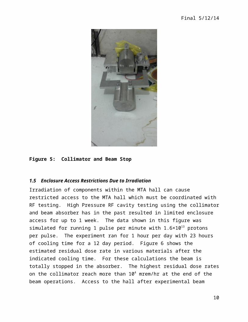
2. The MTA presently supports two modes of beam operation: beam delivery to the upstream emittance beam absorber for performing detailed measurements of Linac beam properties, and beam delivery to the MTA RF test experiments. This second mode utilizes a collimator and dump assembly that can be re-positioned as needed by the various RF experiments. This assembly is shown later in Figure 5.Figure 5: Collimator and Beam Stop Present limits for the two modes of operation are: 600 pulses/hour or 4.5 x 10¹⁵ protons/hour for beam measurements and 60 pulses/hour or 4.5 x 10¹⁴ protons/hour to MTA RF experiments. The two modes are referred to as the Emittance mode and Experiment mode, respectively. In addition MTA supports non-beam operations of an rf cavity in the presence of a magnetic field provided solenoid magnet in the RF Test Stand at the downstream end of the MTA Hall.
Figure 2: The top image is the layout of the MTA line downstream of the shielding wall while the bottom image is the layout upstream of the shielding wall which resides in Linac proper. Only the downstream is accessible concurrent with the operations of High Energy Physics.
4

Final 5/12/14
All experimental configurations are handled operationally through Beam Permits and Running Conditions managed and maintained by the Fermilab Accelerator Division and enforced by the Operations Group. Each experimental configuration is individually evaluated based on its Memorandum of Understanding (MoU) and Operational Readiness Clearance (ORC) for compliance with the approved radiation shielding assessment criteria.
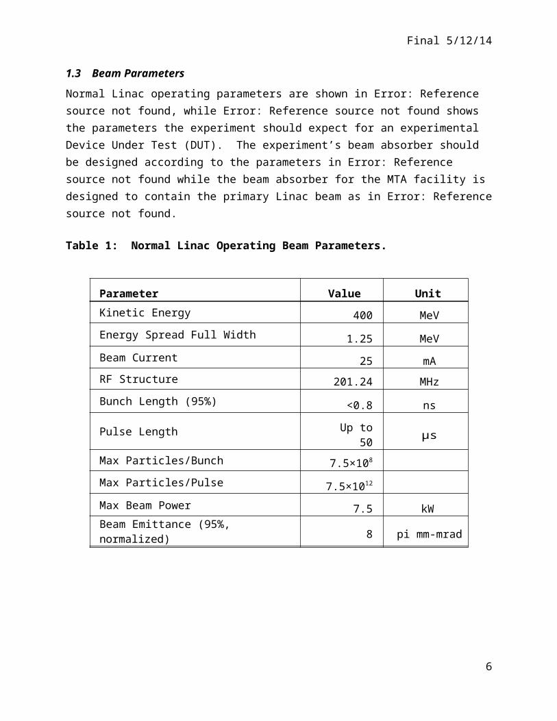
1.3 Beam ParametersNormal Linac operating parameters are shown in Error: Reference source not found, while Error:Reference source not found shows the parameters the experiment should expect for an experimental Device Under Test (DUT). The experiment’s beam absorber should be designed according to the parameters in Error: Reference source not found while the beam absorber for the MTA facility is designed to contain the primary Linac beam as in Error: Reference source not found.
Table 1: Normal Linac Operating Beam Parameters.
Parameter Value UnitKinetic Energy 400 MeV
Energy Spread Full Width 1.25 MeVBeam Current 25 mARF Structure 201.24 MHz
Bunch Length (95%) <0.8 nsPulse Length Up to 50 µsMax Particles/Bunch 7.5×10⁸
Max Particles/Pulse 7.5×10¹²
Max Beam Power 7.5 kWBeam Emittance (95%, normalized) 8 pi mm-mrad
5
Final 5/12/14
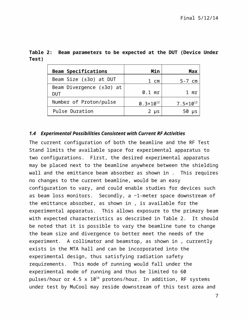
Table 2: Beam parameters to be expected at the DUT (Device Under Test)
Beam Specifications Min Max
Beam Size (±3σ) at DUT 1 cm 5-7 cmBeam Divergence (±3σ) at DUT 0.1 mr 1 mrNumber of Proton/pulse 0.3×10¹² 7.5×10¹²
Pulse Duration 2 µs 50 µs
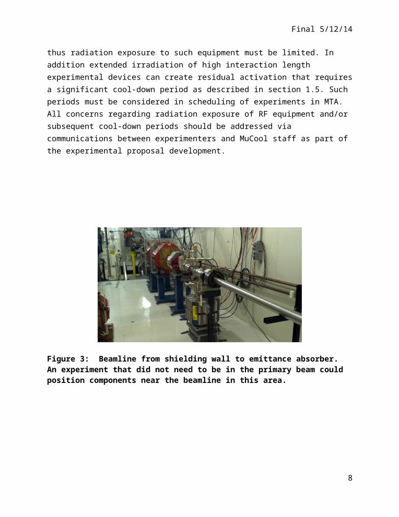
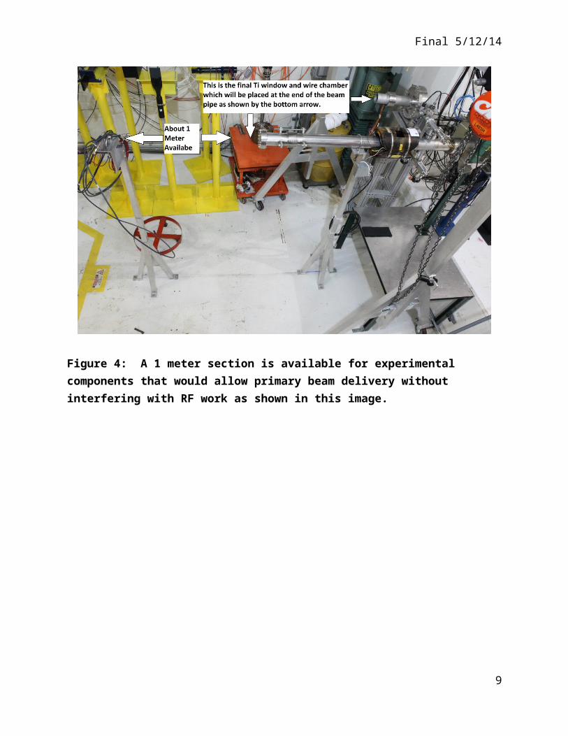
1.4 Experimental Possibilities Consistent with Current RF ActivitiesThe current configuration of both the beamline and the RF Test Stand limits the available space for experimental apparatus to two configurations. First, the desired experimental apparatus may be placed next to the beamline anywhere between the shielding wall and the emittance beam absorber as shown in . This requires no changes to the current beamline, would be an easy configuration to vary, and could enable studies for devices such as beam loss monitors. Secondly, a ~1-meter space downstream of the emittance absorber, as shown in , is available for the experimental apparatus. This allows exposure to the primary beam with expected characteristics as described in Table 2. It should be noted that it is possible to vary the beamline tune to change the beam size and divergence to better meet the needs of the experiment. A collimator and beamstop, as shown in , currently exists in the MTA hall and can be incorporated into the experimental design, thus satisfying radiation safety requirements. This mode of running would fall under the experimental mode of running and thus be limited to 60 pulses/hour or 4.5 x 10¹⁴ protons/hour. In addition, RF systems under test by MuCool may reside downstream of this test area and thus radiation exposure to such equipment must be limited. In addition extended irradiation of high interaction length experimental devices can create residual activation that requires a significant cool-down period as described in section 1.5. Such periods must be considered in scheduling of experiments in MTA. All concerns regarding radiation exposure of RF equipment and/or subsequent cool-down periods should be addressed via communications between experimenters and MuCool staff as part of the experimental proposal development.
6
Final 5/12/14
Figure 3: Beamline from shielding wall to emittance absorber. An experiment that did not need to be in the primary beam could position components near the beamline in this area.
Figure 4: A 1 meter section is available for experimental components that would allow primary beam delivery without interfering with RF work as shown in this image.
7
Final 5/12/14
Figure 5: Collimator and Beam Stop
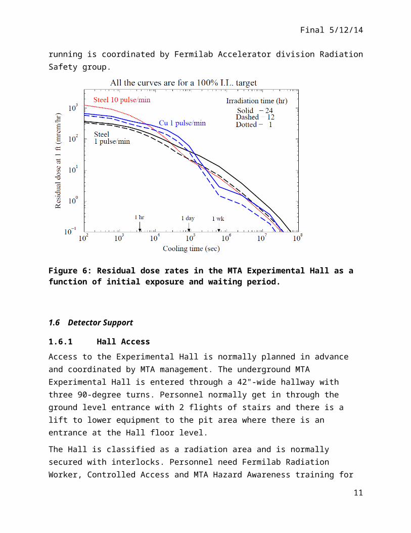
1.5 Enclosure Access Restrictions Due to IrradiationIrradiation of components within the MTA hall can cause restricted access to the MTA hall which must be coordinated with RF testing. High Pressure RF cavity testing using the collimator and beam absorber has in the past resulted in limited enclosure access for up to 1 week. The data shown in this figure was simulated for running 1 pulse per minute with 1.6×10¹³ protons per pulse. The experiment ran for 1 hour per day with 23 hours of cooling time for a 12 day period. Figure 6 shows the estimated residual dose rate in various materials after the indicated cooling time. For these calculations the beam is totally stopped in the absorber. The highest residual dose rates on the collimator reach more than 104 mrem/hr at the end of the beam operations. Access to the hall after experimental beam running is coordinated by Fermilab Accelerator division Radiation Safety group.
8
Final 5/12/14
Figure 6: Residual dose rates in the MTA Experimental Hall as a function of initial exposure and waiting period.
1.6 Detector Support
1.6.1 Hall Access
Access to the Experimental Hall is normally planned in advance and coordinated by MTA management. The underground MTA Experimental Hall is entered through a 42"-wide hallway with three 90-degree turns. Personnel normally get in through the ground level entrance with 2 flights of stairs and there is a lift to lower equipment to the pit area where there is an entrance at the Hall floor level.
The Hall is classified as a radiation area and is normally secured with interlocks. Personnel need Fermilab Radiation Worker, Controlled Access and MTA Hazard Awareness training for access and a radiation survey by ES&H is normally required after any beam running before access is granted. A personal frisker in the entrance hallway is used on exit from the enclosure.
The RF power source is interlocked to the doors so Hall access is not possible while an RF cavity experiment is running. Hall access is normally not allowed when there is flammable and/or high-pressure gas present.
Maximum occupancy in the Hall is limited to 12 people at any time. The practical limit is set by the 10 keys available for access.
9
Final 5/12/14
1.6.2 Mechanical Infrastructure
There is about 1m of space along the beam direction available downstream of the emittance absorber that could be utilized causing minimal interference with access to solenoid bore. Utlilzation of space beyond 1 m could interfere with the need for access to the RF Test Stand. Any request to utilize this space must be authorized by the MTA Director (see sections 1.6 and 2). There is some space next to the beamline and elsewhere in the Hall for equipment but the Hall is very crowded and details should be negotiated on a case-by-case basis. A stand is needed to hold the equipment under test in the beam (height about 2m). A portable A-frame crane is kept in the Hall and has a half-ton hoist. There is also an overhead monorail crane in the downstream portion of the hall with a 5-ton hoist.
1.6.3 Assembly Work in the Hall
The Hall is kept as an approximately class-1000 clean area. No cutting, drilling, grinding, welding or other operations that might introduce particulate contamination are allowed. Shoe covers are required during any access. Gloves are required during controlled access and additional protection (coveralls) has to be used when working on or near beamline elements or experimental hardware that has been exposed to beam. All tools and equipment being brought into the Hall has to be wiped down for cleanliness on the way in and surveyed for radioactive contamination on the way out. A 5' × 10' portable clean room is available in the Hall for clean assembly and inspection work and can go down to class 10-100. Space in the clean room may be limited due to other hardware kept there.
There is no storage space in the Hall. Arrangements need to be made with Fermilab ES&H for removing any hardware activated by beam from the Hall.
1.6.4 Electrical Service
Standard 15A and 20A 110V single-phase electrical outlets are available for plugging in equipment in the Hall but spare electrical capacity is limited. Available 220V outlets are currently in use for the solenoid power supply and the clean room. Most circuits are powered off and locked out for safety when the Hall is in hydrogen mode.
1.6.5 Water
Low-conductivity (1-18 Mohm-cm) water supply in the Hall used for RF experiments is part of a closed system driven by a chiller with up to 10-20 gpm flow and 16kW of cooling capacity near room temperature. Spare cooling capacity depends on RF operations. The Linac LCW system is connected to beamline magnets and may have some spare capacity.
10
Final 5/12/14
1.6.6 Vacuum
There are 2 fixed vacuum systems in the hall. Both systems are used for RF experiments. Any needed vacuum equipment must be provided by the experiment.
1.6.7 Instrumentation, Data Acquisition, and Networking
1/2" and 1/4" heliax, RG58 and shielded twisted-pair cables from the Hall to the Linac gallery exist but are in use for RF experiments. The signal path to the Linac gallery is about 425 ns. There are also cables running to the Refrigerator Room near the Hall which is a shorter path (about 50 m). Due to limited cabling any cable needs must be carefully evaluated with relationship to RF testing.
The Fermilab wireless network is available in the Hall. There are also switches for the Fermilab wired network (use of which requires permission from the controls network group) and a private local network which extends to the Refrigerator Room and Linac Gallery. Experimenters are encouraged to locate there equipment for data acquisition in the MTA hall and capitalize on the network for remote acquisition. Four ionization chambers are used in the Hall to measure dose rates.
A NaI crystal detector, equipped with a PMT, can be used for X-ray spectrometry. Several other counters are made of plastic scintillator paddles equipped with PMTs. There are also clear fibers and a visible-light spectrometer.
The positioning and availability of the existing detectors depends on RF operational needs.
1.6.8 Beam Instrumentation
The beam pipe must be terminated by a thin Ti window where the H- beam is stripped. A multiwire chamber (MW8) can be installed at the end of the beamline just upstream of the Ti window. It has 2 fixed planes, each with 48 wires spaced 2mm. Both the multiwire and Ti window can be seen in Figure 4 though not in final positions. The next multiwire upstream (MW7) is another 1m or so away and has 2 planes with 1mm spacing, one of the planes at a time can be placed into/out of the beam. There is a toroid for measuring beam current right upstream of MW7 and a beam position monitor upstream of the last quad (Q12). Readout for beamline instrumentation is through Fermilab's standard ACNET system. An air SWIC and a scintillating screen with a CCD camera were also used for measuring the beam spot in the past.
11
Final 5/12/14
1.6.9 Magnet
A superconducting solenoid is installed in the center of the Hall and has a pair of Helmholtz coils that can be powered individually, or with the same (for a solenoidal field) or opposite polarity (for a gradient field). It has a warm bore of 44cm diameter by 1m length. The central field at the rated current in solenoid mode is 5T. The magnetic field falls off rapidly away from the center of the magnet. Any ferrous objects left around the magnet could be pulled in with great force and cause damage to the magnet and other equipment inside and around it. In addition, any personnel standing between such an object and the magnet would be at risk of serious injury. A clearly marked buffer zone, demarcated with warning signs and a barricade is maintained around the magnet when the magnetic field is present. The area designated for proposed experiments is outside of this buffer zone and no experimental equipment will be allowed within this buffer zone. MTA personnel are responsible for ensuring the magnetic field region is free of any ferrous material before powering of the solenoid.
1.6.10 Gas lines
Two gas lines run from the Hall to the manifold room at ground level where gas bottles are kept.
1.7 Process for Approving Experimental Tests at MTA The Muon Accelerator Program (MAP) is the primary user of the MTA. It is anticipated that an operating schedule for MTA will be established on an annual basis, with ~one month set aside for users outside of MAP.
Initial experimental requests for MTA facility access should be channeled through the MTA Director and MTA Coordinator. The process for requesting beam time in the MTA facility parallels the process for requesting beam at the Fermi Test Beam facility. This process is outlined at the following web page, which should be used as a guideline for preparation of any request to mount an experiment at MTA: http://www-ppd.fnal.gov/ftbf/BeAUser/Page1.html . Authorization to mount an experiment will be granted in writing by the MAP Director, MTA Director and Coordinator, in addition to the standard Accelerator Division operations authorizations.
2 Capabilities inconsistent with concurrent RF activitiesAlthough there is additional space available between the end of the current primary beamline and the upstream end of the RF test area, this space is utilized and needed for changes within the RF systems under test by MuCool. Cavities, configurations, and RF sources change on a regular basis in this region. In addition, certain test equipment may not be compatible with concurrent operations of the RF Test Stand. Hence any experimental setup that requires more space than the
12
Final 5/12/14
1 meters described above and/or is proposed for concurrent operations of the RF Test Stand will require special coordination with the MuCool Staff and authorization by the MTA Director.
13


![MTA - Unopomp · TM01 8522 0300 MTA 3 MTA 4 L[mm] 35 45 TM01 8657 0600 TM01 8658 0600 TM01 9076 1000 10 L 10 125 45 Min. 20 mm General data MTA. 6 Technical data MTA 3 MTA 4 ... 105](https://img.pdfslide.us/doc/110x75/5be789d309d3f246788ca2ff/mta-tm01-8522-0300-mta-3-mta-4-lmm-35-45-tm01-8657-0600-tm01-8658-0600-tm01.jpg)