Embed Size (px)
Citation preview
VIII•IX•X ICSE • XI(Sc) • XII(Sc) • CET/JEE(M)/NEET • IGCSE •CBSE• IB • HL & SL + A & AS • EngineeringTelephone: 9820246760 / 9769479368 • Websites:navlakhi.com –or– navlakhi.educationEmail: [email protected] –or– [email protected]
2020 - 2021
KIRCHHOFF’s LAWSKirchhoff’s first law (Current Law or Junction Law):The algebraic sum of electric current at any junction isalways equal to zero. ΣI = 0The current flowing towards the junction is positive andcurrent flowing away from the junction is negativeI1 + I3 + I5 – I2 – I4 = 0 OR I1 + I3 + I5 = I2 + I4
NOTE: This law is in accordance with law of conservation of charge
Kirchhoff’s second Law (Voltage law or loop theorem): In a closed loop ofelectrical network, the algebraic sum of potential differences for allcomponents plus the algebraic sum of all E.M.F. is equal to zero.
ΣIR + ΣE = 0In the direction of conventional current flow the potential differenceacross the resistances is negative otherwise positive. For EMF if we travelfrom negative to positive terminal then we take it positive otherwisenegative.
WHEATSTONE’S NETWORKFor accurate measurement of unknown resistance4 resistors connected to form a quadrilateral ABCD. A battery of E volts isconnected between A & C. A galvanometer is connected between the endsB and C having resistance G.Network is said to be balanced ifVB=VD , hence Ig=0(current through galvanometer iszero, called NULL POINT)Proof: Applying KVL to ABGDA-I1P + I2S = 0 , thus, I1P = I2SApplying KVL to BCDGB-I1Q + I2R = 0, thus, I1Q = I2RDividing we get P/Q = S/R ,alternately, PR=QSThis is the balancing condition.NOTE: If the bridge is balanced Ig = 0 , Thus P and Q and in series and so isS and R. Thus, total resistance of circuit is (P+Q)//(S+R)
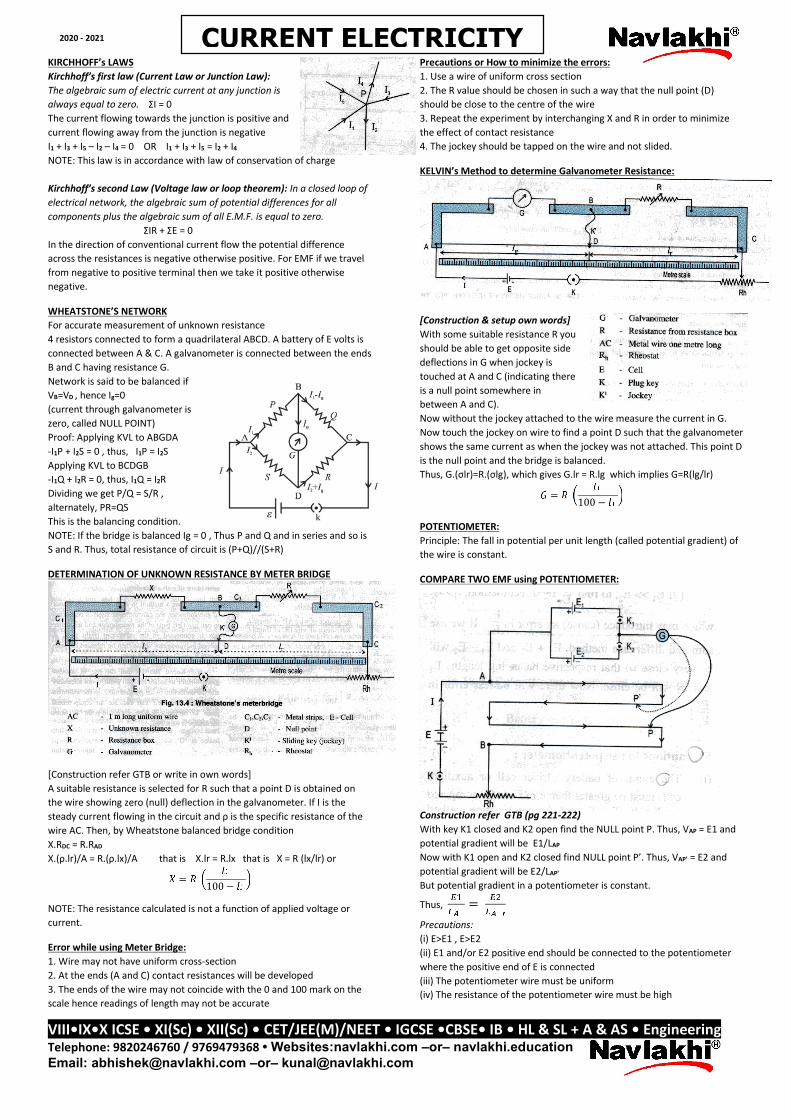
DETERMINATION OF UNKNOWN RESISTANCE BY METER BRIDGE
[Construction refer GTB or write in own words]A suitable resistance is selected for R such that a point D is obtained onthe wire showing zero (null) deflection in the galvanometer. If I is thesteady current flowing in the circuit and ρ is the specific resistance of thewire AC. Then, by Wheatstone balanced bridge conditionX.RDC = R.RAD
X.(ρ.lr)/A = R.(ρ.lx)/A that is X.lr = R.lx that is X = R (lx/lr) or= 100 −NOTE: The resistance calculated is not a function of applied voltage orcurrent.
Error while using Meter Bridge:1. Wire may not have uniform cross-section2. At the ends (A and C) contact resistances will be developed3. The ends of the wire may not coincide with the 0 and 100 mark on thescale hence readings of length may not be accurate
Precautions or How to minimize the errors:1. Use a wire of uniform cross section2. The R value should be chosen in such a way that the null point (D)should be close to the centre of the wire3. Repeat the experiment by interchanging X and R in order to minimizethe effect of contact resistance4. The jockey should be tapped on the wire and not slided.
KELVIN’s Method to determine Galvanometer Resistance:
[Construction & setup own words]With some suitable resistance R youshould be able to get opposite sidedeflections in G when jockey istouched at A and C (indicating thereis a null point somewhere inbetween A and C).Now without the jockey attached to the wire measure the current in G.Now touch the jockey on wire to find a point D such that the galvanometershows the same current as when the jockey was not attached. This point Dis the null point and the bridge is balanced.Thus, G.(σlr)=R.(σlg), which gives G.lr = R.lg which implies G=R(lg/lr)= 100 −POTENTIOMETER:Principle: The fall in potential per unit length (called potential gradient) ofthe wire is constant.
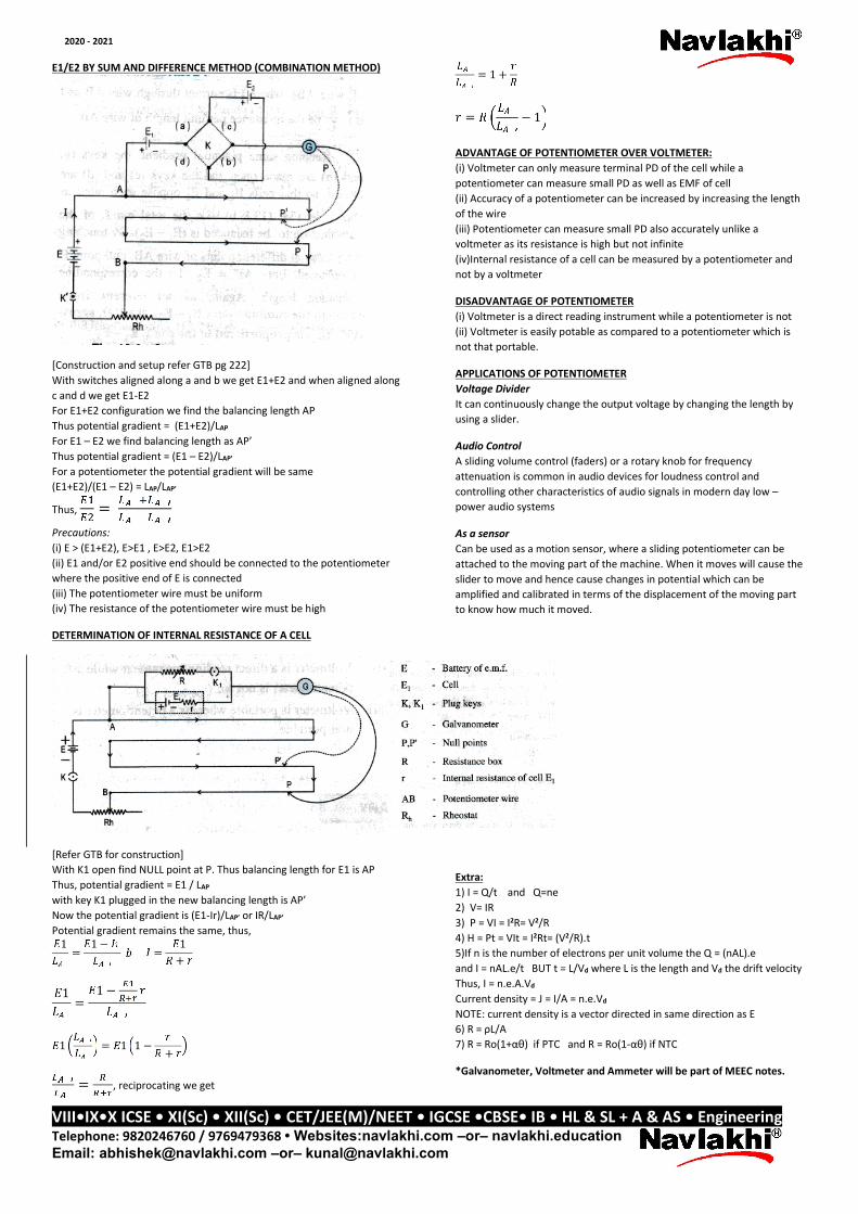
COMPARE TWO EMF using POTENTIOMETER:
Construction refer GTB (pg 221-222)With key K1 closed and K2 open find the NULL point P. Thus, VAP = E1 andpotential gradient will be E1/LAP
Now with K1 open and K2 closed find NULL point P’. Thus, VAP’ = E2 andpotential gradient will be E2/LAP’
But potential gradient in a potentiometer is constant.
Thus, =Precautions:(i) E>E1 , E>E2(ii) E1 and/or E2 positive end should be connected to the potentiometerwhere the positive end of E is connected(iii) The potentiometer wire must be uniform(iv) The resistance of the potentiometer wire must be high
CURRENT ELECTRICITY
VIII•IX•X ICSE • XI(Sc) • XII(Sc) • CET/JEE(M)/NEET • IGCSE •CBSE• IB • HL & SL + A & AS • EngineeringTelephone: 9820246760 / 9769479368 • Websites:navlakhi.com –or– navlakhi.educationEmail: [email protected] –or– [email protected]
2020 - 2021
E1/E2 BY SUM AND DIFFERENCE METHOD (COMBINATION METHOD)
[Construction and setup refer GTB pg 222]With switches aligned along a and b we get E1+E2 and when aligned alongc and d we get E1-E2For E1+E2 configuration we find the balancing length APThus potential gradient = (E1+E2)/LAP
For E1 – E2 we find balancing length as AP’Thus potential gradient = (E1 – E2)/LAP’
For a potentiometer the potential gradient will be same(E1+E2)/(E1 – E2) = LAP/LAP’
Thus, =Precautions:(i) E > (E1+E2), E>E1 , E>E2, E1>E2(ii) E1 and/or E2 positive end should be connected to the potentiometerwhere the positive end of E is connected(iii) The potentiometer wire must be uniform(iv) The resistance of the potentiometer wire must be high
DETERMINATION OF INTERNAL RESISTANCE OF A CELL
[Refer GTB for construction]With K1 open find NULL point at P. Thus balancing length for E1 is APThus, potential gradient = E1 / LAP
with key K1 plugged in the new balancing length is AP’Now the potential gradient is (E1-Ir)/LAP’ or IR/LAP’
Potential gradient remains the same, thus,1 = 1 − = 1+1 = 1 −1 = 1 1 − += , reciprocating we get
= 1 += − 1
ADVANTAGE OF POTENTIOMETER OVER VOLTMETER:(i) Voltmeter can only measure terminal PD of the cell while apotentiometer can measure small PD as well as EMF of cell(ii) Accuracy of a potentiometer can be increased by increasing the lengthof the wire(iii) Potentiometer can measure small PD also accurately unlike avoltmeter as its resistance is high but not infinite(iv)Internal resistance of a cell can be measured by a potentiometer andnot by a voltmeter
DISADVANTAGE OF POTENTIOMETER(i) Voltmeter is a direct reading instrument while a potentiometer is not(ii) Voltmeter is easily potable as compared to a potentiometer which isnot that portable.
APPLICATIONS OF POTENTIOMETERVoltage DividerIt can continuously change the output voltage by changing the length byusing a slider.
Audio ControlA sliding volume control (faders) or a rotary knob for frequencyattenuation is common in audio devices for loudness control andcontrolling other characteristics of audio signals in modern day low –power audio systems
As a sensorCan be used as a motion sensor, where a sliding potentiometer can beattached to the moving part of the machine. When it moves will cause theslider to move and hence cause changes in potential which can beamplified and calibrated in terms of the displacement of the moving partto know how much it moved.
Extra:1) I = Q/t and Q=ne2) V= IR3) P = VI = I2R= V2/R4) H = Pt = VIt = I2Rt= (V2/R).t5)If n is the number of electrons per unit volume the Q = (nAL).eand I = nAL.e/t BUT t = L/Vd where L is the length and Vd the drift velocityThus, I = n.e.A.Vd
Current density = J = I/A = n.e.Vd
NOTE: current density is a vector directed in same direction as E6) R = ρL/A7) R = Ro(1+αθ) if PTC and R = Ro(1-αθ) if NTC
*Galvanometer, Voltmeter and Ammeter will be part of MEEC notes.