Embed Size (px)
Citation preview
Developments in Friction Stir Welding of Thin Automotive Sheet Steels:A Microstructural Comparison
Center for Welding, Joining and Coatings ResearchDepartment of Metallurgical and Materials Engineering
Colorado School of Mines
Golden, Colorado
Scott Gordon and Stephen Liu
Current Developments in Ferrous Alloys, MTGN 5497 December, 2009

Outline of Presentation
‣Background Information‣Purpose of Study‣Experimental Program‣Results and Discussion‣Summary‣Acknowledgments
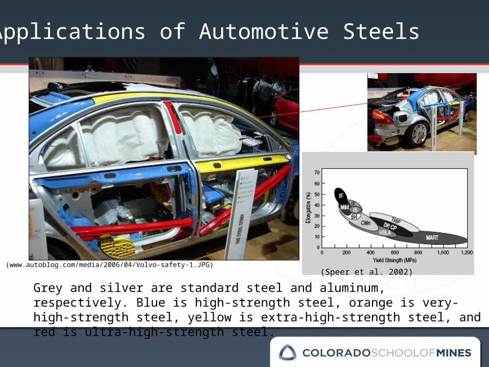
Grey and silver are standard steel and aluminum, respectively. Blue is high-strength steel, orange is very-high-strength steel, yellow is extra-high-strength steel, and red is ultra-high-strength steel.
(www.autoblog.com/media/2006/04/Volvo-safety-1.JPG) (Speer et al. 2002)
Applications of Automotive Steels
‣ Solid-state welding process‣ Final weldment can have significant grain refinement depending on
initial microstructure with favorable mechanical properties‣ High equipment cost limiting its use to selected industrial
applications, e.g. in some European trains, rockets components, jets, race car frames, armor plating, etc…
‣ This is a “green” welding process lending itself to little environmental impact
‣ Process is still little known to the overall welding industry, therefore it has not been accepted by the industrial community as a viable process
Background
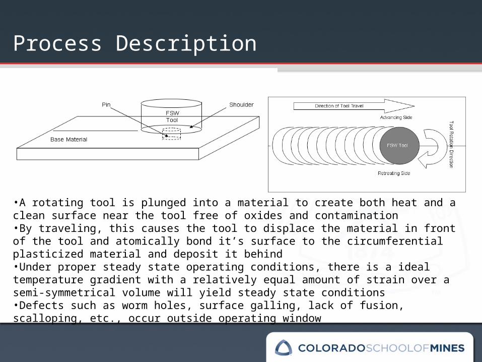
Process Description
•A rotating tool is plunged into a material to create both heat and a clean surface near the tool free of oxides and contamination •By traveling, this causes the tool to displace the material in front of the tool and atomically bond it’s surface to the circumferential plasticized material and deposit it behind•Under proper steady state operating conditions, there is a ideal temperature gradient with a relatively equal amount of strain over a semi-symmetrical volume will yield steady state conditions•Defects such as worm holes, surface galling, lack of fusion, scalloping, etc., occur outside operating window
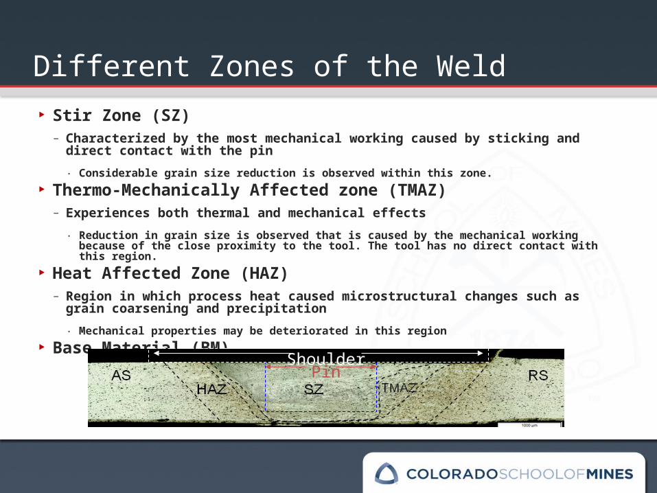
Different Zones of the Weld‣ Stir Zone (SZ)
– Characterized by the most mechanical working caused by sticking and direct contact with the pin‧ Considerable grain size reduction is observed within this zone.
‣ Thermo-Mechanically Affected zone (TMAZ)– Experiences both thermal and mechanical effects
‧ Reduction in grain size is observed that is caused by the mechanical working because of the close proximity to the tool. The tool has no direct contact with this region.
‣ Heat Affected Zone (HAZ)– Region in which process heat caused microstructural changes such as grain
coarsening and precipitation‧ Mechanical properties may be deteriorated in this region
‣ Base Material (BM).
PinShoulder
Purpose of Work
To show that FSW is a viable process to join advanced automotive steel sheets, but that proper precautions and setup need to be taken in order to assure a quality joint
To design a tool that is versatile for usage and service
To develop process parameters for friction stir welding of thin steel sheets
To examine the macro & microstructures of welds produced in similar and dissimilar joints of advanced automotive steels
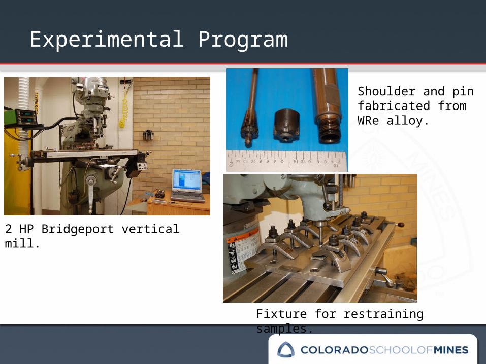
2 HP Bridgeport vertical mill.
Shoulder and pin fabricated from WRe alloy.
Fixture for restraining samples.
Experimental Program
Pin and Shoulder Design
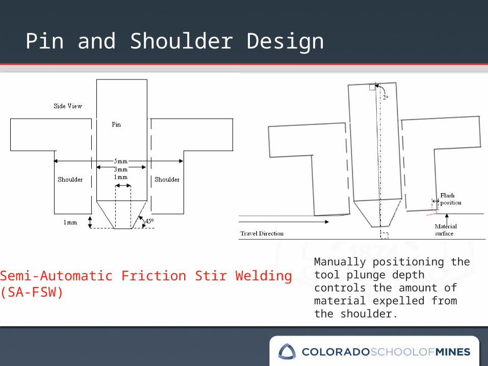
Manually positioning the tool plunge depth controls the amount of material expelled from the shoulder.
Semi-Automatic Friction Stir Welding (SA-FSW)
Experimental Materials
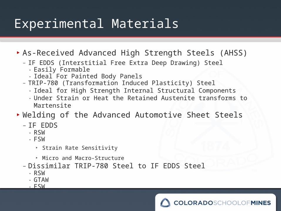
‣ As-Received Advanced High Strength Steels (AHSS) – IF EDDS (Interstitial Free Extra Deep Drawing) Steel
‧ Easily Formable ‧ Ideal For Painted Body Panels
– TRIP-780 (Transformation Induced Plasticity) Steel‧ Ideal for High Strength Internal Structural Components‧ Under Strain or Heat the Retained Austenite transforms to Martensite
‣ Welding of the Advanced Automotive Sheet Steels – IF EDDS
‧ RSW‧ FSW
‣ Strain Rate Sensitivity ‣ Micro and Macro-Structure
– Dissimilar TRIP-780 Steel to IF EDDS Steel‧ RSW ‧ GTAW‧ FSW
Sample Preparation and Characterization
‣ Samples were cross sectioned at the midpoint of the weld to assume the most steady state condition.
‣ Grinding and polishing with SiC paper; Suspended diamond for rough and fine polishing steps.
‣ Two-Stage Color Tint Etch Process: The polished surface was immersed in a 2% Picral with 1-3 drops of hydrochloric acid in a Petri dish for 12-15 seconds, rinsed with ethanol, followed by water, then submersed in a 7.5% sodium metabisulfite and water solution for 6 seconds. The samples were rinsed in water followed by ethanol, and then dried.
‣ Light Microscopy was used to examine the surface.
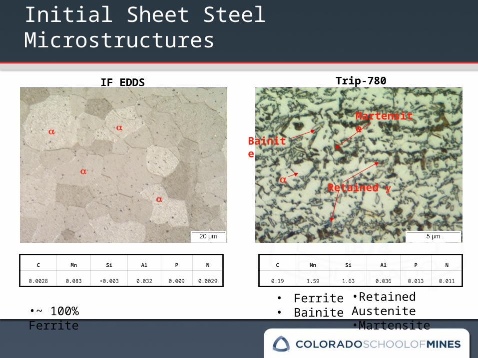
0.0110.0130.0361.631.590.19
NPAlSiMnC
0.00290.0090.032<0.0030.0830.0028
NPAlSiMnC
•~ 100% Ferrite• Ferrite• Bainite
IF EDDS Trip-780
•Retained Austenite •Martensite
Bainite
Retained
Martensite
Initial Sheet Steel Microstructures
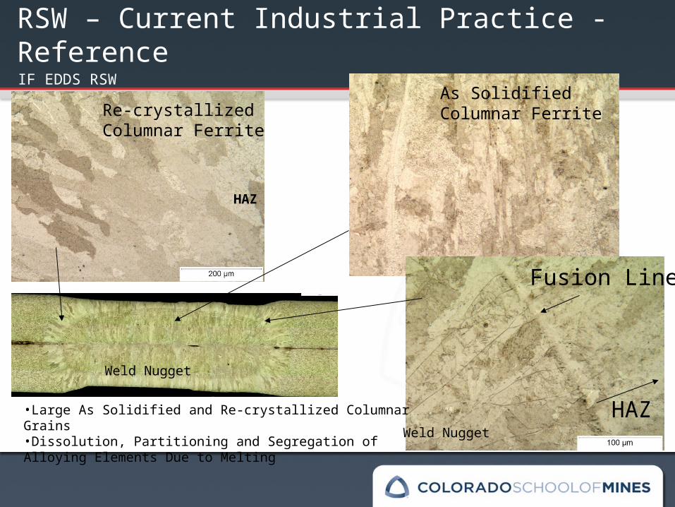
IF EDDS RSW
Re-crystallized Columnar Ferrite
Fusion Line
As Solidified Columnar Ferrite
Weld Nugget
Weld Nugget HAZ
HAZ
•Large As Solidified and Re-crystallized Columnar Grains•Dissolution, Partitioning and Segregation of Alloying Elements Due to Melting
RSW – Current Industrial Practice - Reference
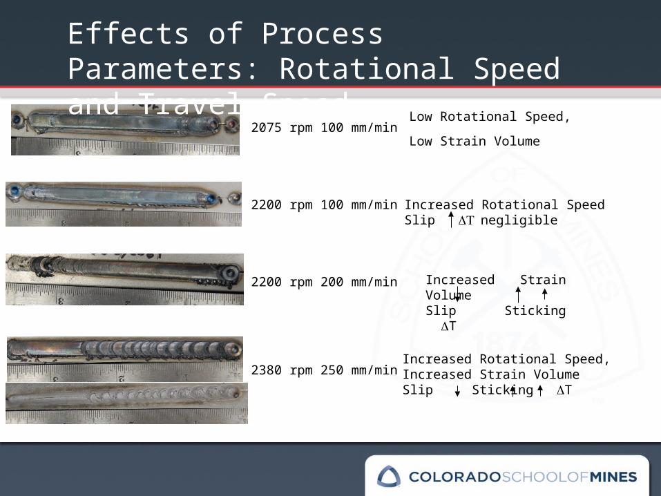
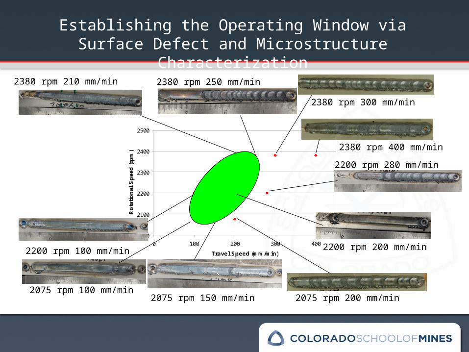
2200 rpm 200 mm/min
2075 rpm 100 mm/min
2380 rpm 250 mm/min
2200 rpm 100 mm/min
Effects of Process Parameters: Rotational Speed and Travel Speed
Increased Rotational SpeedSlip negligible
Low Rotational Speed,
Low Strain Volume
Increased Rotational Speed,Increased Strain VolumeSlip Sticking T
Increased Strain VolumeSlip Sticking T
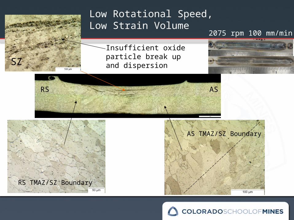
2075 rpm 100 mm/min
Insufficient oxide particle break up and dispersion
ASRS
RS TMAZ/SZ Boundary
AS TMAZ/SZ Boundary
SZ
Low Rotational Speed,Low Strain Volume
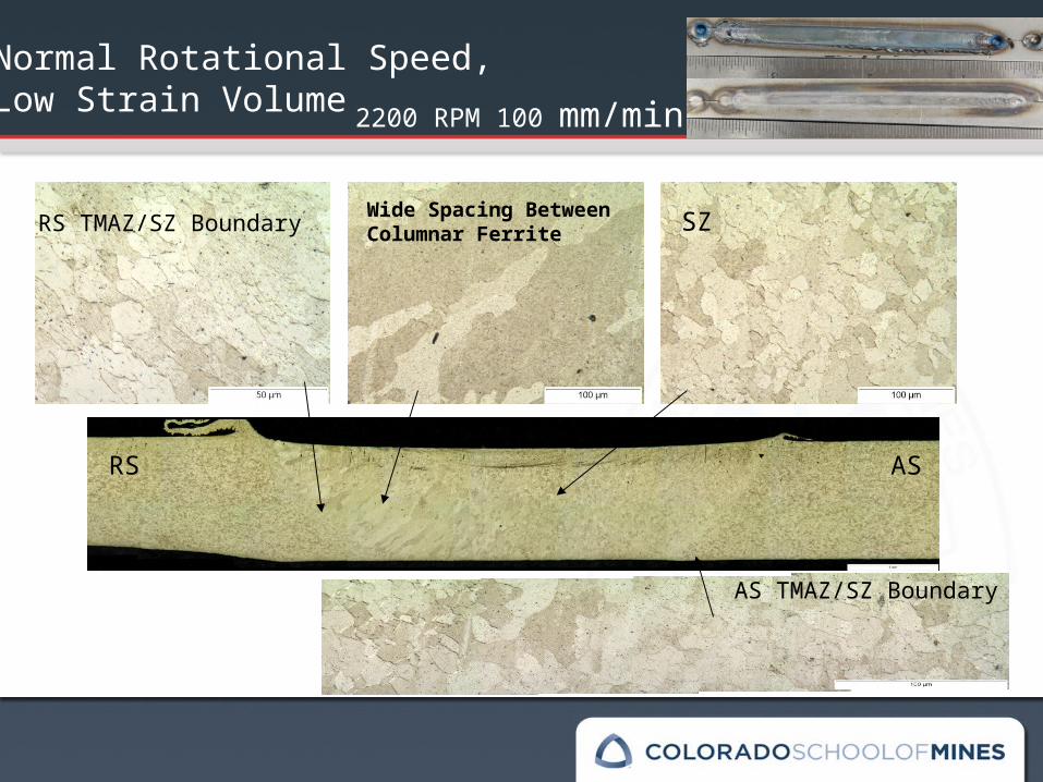
2200 RPM 100 mm/min
Wide Spacing Between Columnar Ferrite
ASRS
RS TMAZ/SZ Boundary SZ
AS TMAZ/SZ Boundary
Normal Rotational Speed,Low Strain Volume
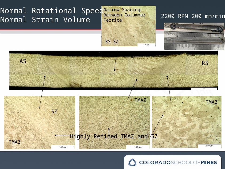
2200 RPM 200 mm/min
Highly Refined TMAZ and SZ
AS RS
TMAZ
SZ
TMAZ TMAZ
Narrow Spacing Between Columnar Ferrite
RS SZ
Normal Rotational Speed,Normal Strain Volume
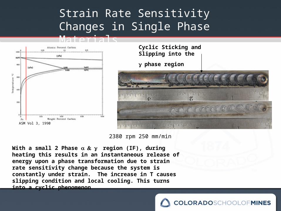
2380 rpm 250 mm/min
With a small 2 Phase region (IF), during heating this results in an instantaneous release of energy upon a phase transformation due to strain rate sensitivity change because the system is constantly under strain. The increase in T causes slipping condition and local cooling. This turns into a cyclic phenomenon
Strain Rate Sensitivity Changes in Single Phase Materials
ASM Vol 3, 1990
Cyclic Sticking and Slipping
into the phase region
2000
2100
2200
2300
2400
2500
0 100 200 300 400
Travel Speed (mm/min)
Rot
atio
nal S
peed
(rpm
)
2200 rpm 200 mm/min
2200 rpm 280 mm/min
2200 rpm 100 mm/min
2075 rpm 150 mm/min2075 rpm 100 mm/min
2380 rpm 210 mm/min 2380 rpm 250 mm/min
2075 rpm 200 mm/min
2380 rpm 300 mm/min
2380 rpm 400 mm/min
Establishing the Operating Window via Surface Defect and Microstructure Characterization
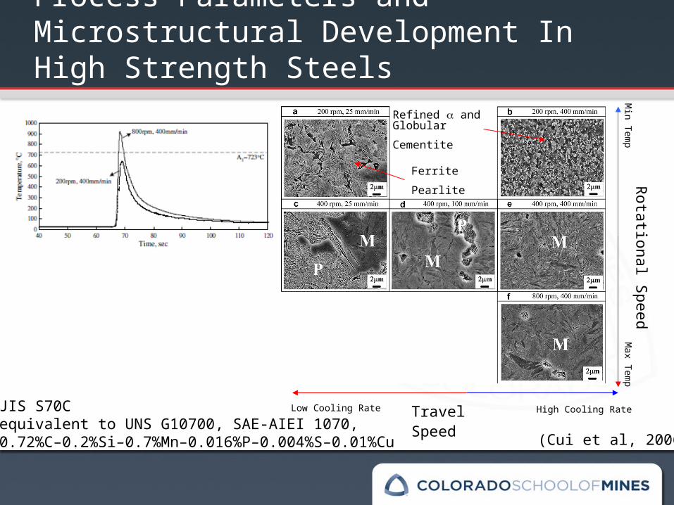
Process Parameters and Microstructural Development In High Strength Steels
JIS S70Cequivalent to UNS G10700, SAE-AIEI 1070,0.72%C–0.2%Si–0.7%Mn–0.016%P–0.004%S–0.01%Cu
Rotational S
peed
Travel Speed (Cui et al, 2006)
Refined and
Globular Cementite
Ferrite Pearlite
High Cooling RateLow Cooling Rate
Max Tem
p M
in Temp
IF EDDS
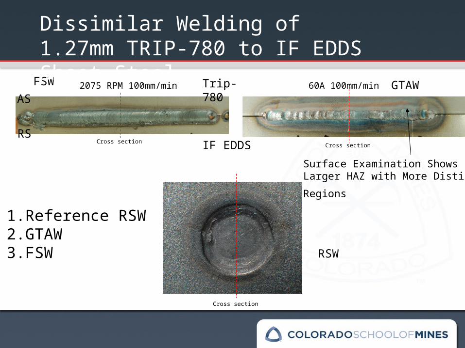
Trip-780FSW GTAW
RSW
Cross section
Cross section
Cross section
AS
RS
Dissimilar Welding of 1.27mm TRIP-780 to IF EDDS Sheet Steel
60A 100mm/min2075 RPM 100mm/min
Surface Examination Shows Larger
HAZ with More Distinct Regions
1. Reference RSW2. GTAW3. FSW
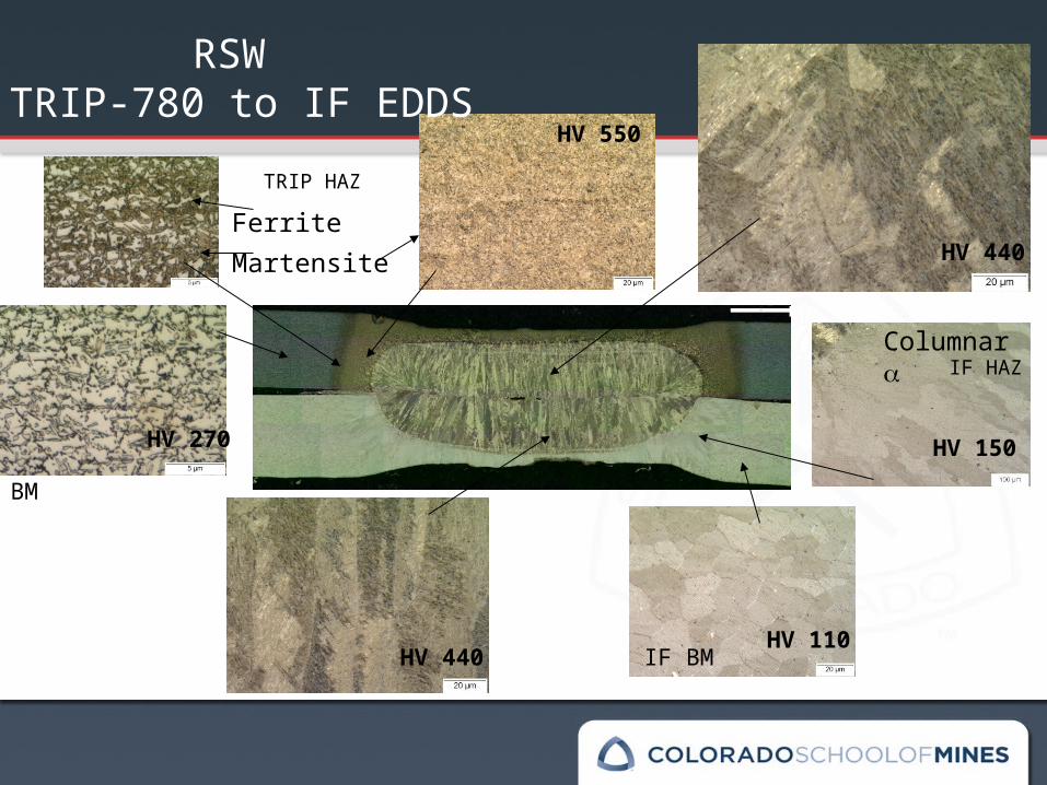
RSW TRIP-780 to IF EDDS
FerriteMartensite
Columnar
BM
IF BM
TRIP HAZ
IF HAZ
HV 550
HV 150
HV 110HV 440
HV 270
HV 440
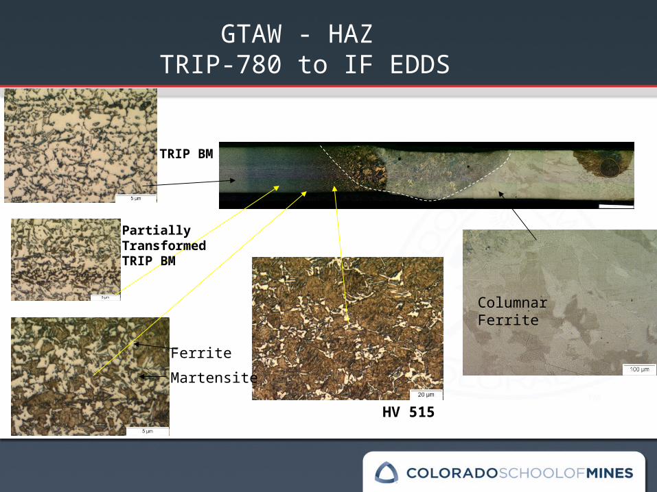
GTAW - HAZ TRIP-780 to IF EDDS
Columnar Ferrite
Ferrite
Martensite
TRIP BM
PartiallyTransformed TRIP BM
HV 515
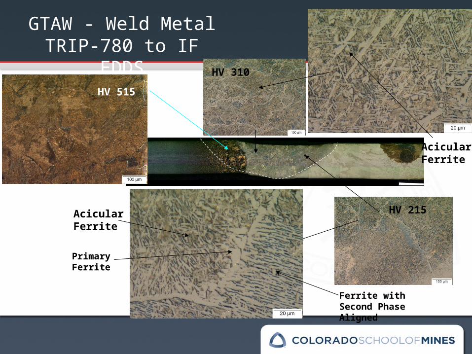
GTAW - Weld Metal TRIP-780 to IF EDDS
Acicular Ferrite
Ferrite with Second Phase Aligned
Primary Ferrite
Acicular Ferrite
HV 515
HV 310
HV 215
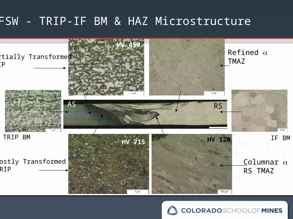
AS RS
FSW - TRIP-IF BM & HAZ Microstructure
Refined TMAZ
TRIP BM IF BM
Partially Transformed TRIP
Mostly Transformed TRIP
Columnar RS TMAZ
HV 450
HV 715 HV 120
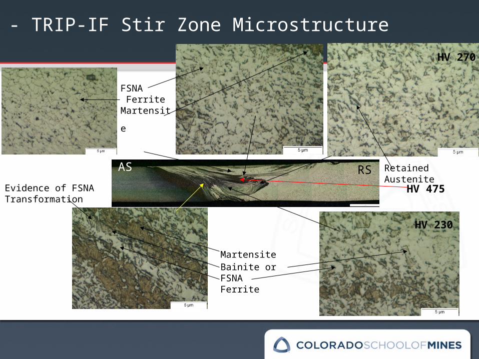
AS RS
FSW - TRIP-IF Stir Zone Microstructure
FSNA Ferrite
Martensite
Retained Austenite
Evidence of FSNA Transformation
Martensite Bainite or FSNAFerrite
HV 230
HV 270
HV 475
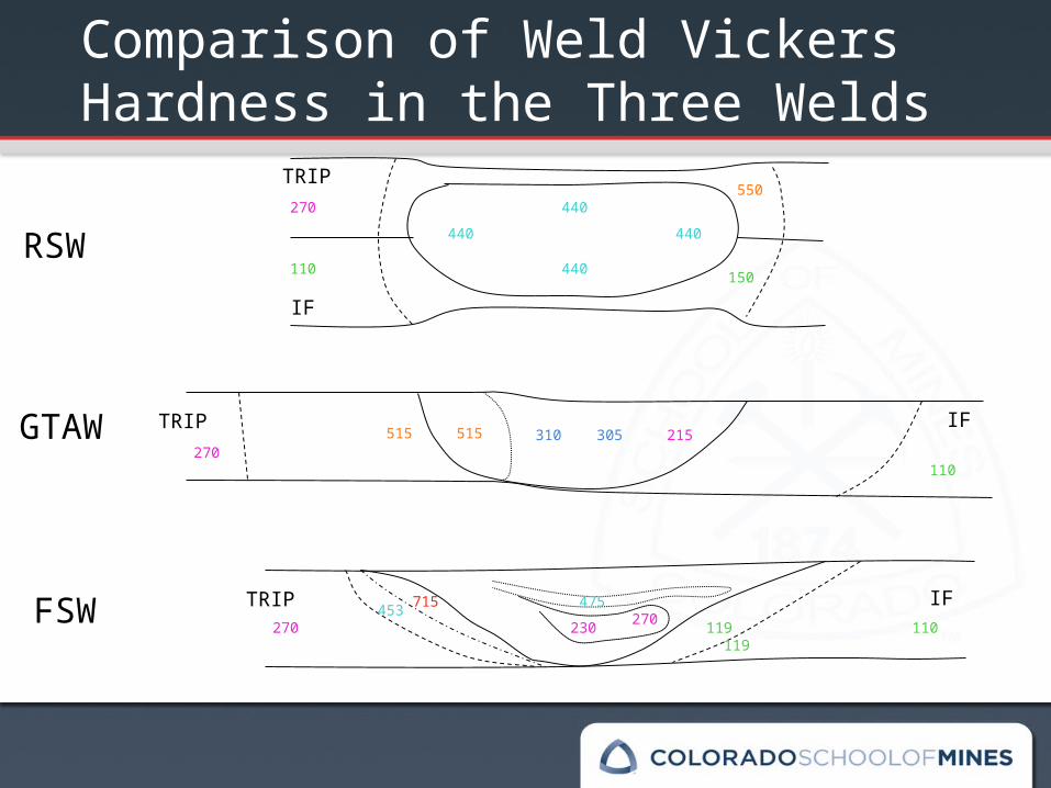
TRIP
IF
RSW
TRIP IFGTAW
FSW TRIP IF
110
270550
440
440
440440
515 310 305 215515
715453230 270
475
119
150
Comparison of Weld Vickers Hardness in the Three Welds
270
270
110
110119
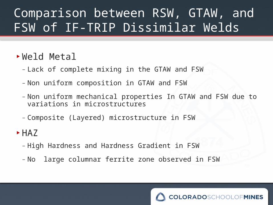
Comparison between RSW, GTAW, and FSW of IF-TRIP Dissimilar Welds
‣Weld Metal– Lack of complete mixing in the GTAW and FSW– Non uniform composition in GTAW and FSW– Non uniform mechanical properties In GTAW and FSW due to
variations in microstructures– Composite (Layered) microstructure in FSW
‣HAZ– High Hardness and Hardness Gradient in FSW– No large columnar ferrite zone observed in FSW
Summary ‣Welding parameters must be appropriately selected to
perform welding on materials that have a phase change associated with heating
‣A wide range of final microstructures can be produced by varying the welding parameters, set up, and alloy selection
‣Less volume of transformations were observed in the base metal and HAZ microstructures in the FSW than the other two fusion processes
‣It will be interesting to conduct mechanical testing to characterize the mechanical properties and fracture behavior of the welds
Acknowledgments
‣George ParaskosAK Steel Research, Middletown, Ohio
‣Dr. Alex Landau Ben Gurion University, Ber Sheeva, Israel
‣Dr. Gerard MartinsColorado School of Mines, Golden, Colorado

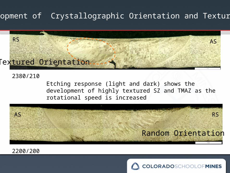
2380/210Etching response (light and dark) shows the development of highly textured SZ and TMAZ as the rotational speed is increased
2200/200
Development of Crystallographic Orientation and Texture
Random Orientation
Textured Orientation
ASRS
AS RS
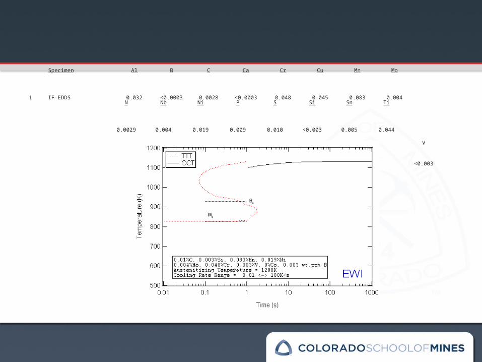
Specimen Al B C Ca Cr Cu Mn Mo
1 IF EDDS 0.032 <0.0003 0.0028 <0.0003 0.048 0.045 0.083 0.004N Nb Ni P S Si Sn Ti
0.0029 0.004 0.019 0.009 0.010 <0.003 0.005 0.044
V
<0.003
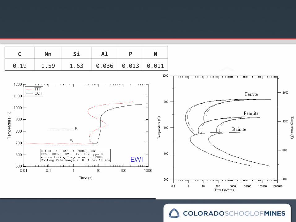
C Mn Si Al P N
0.19 1.59 1.63 0.036 0.013 0.011
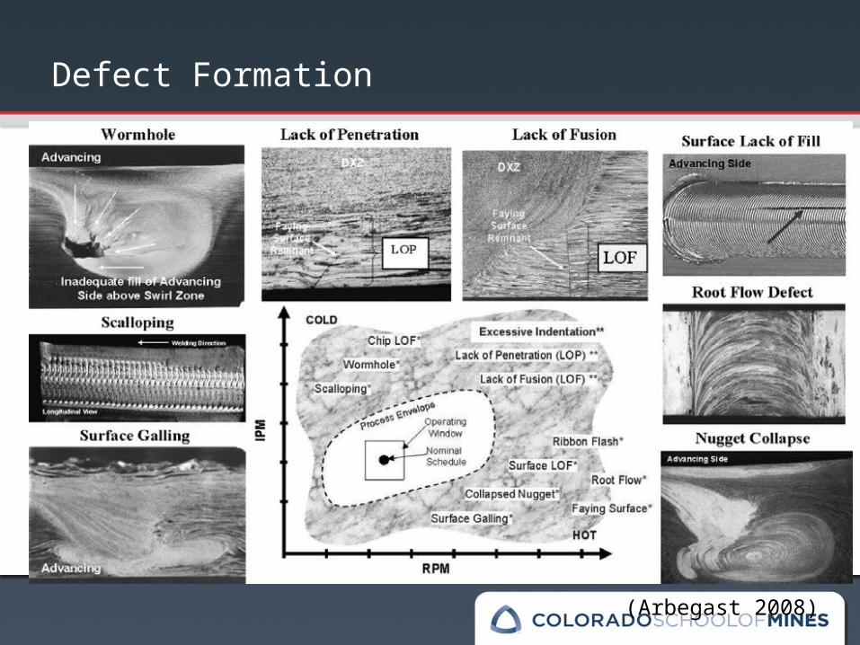
(Arbegast 2008)
Defect Formation
Defect Formation
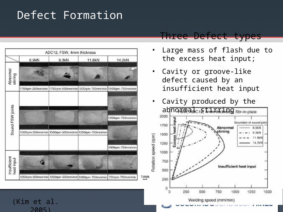
(Kim et al. 2005)
Three Defect types • Large mass of flash due to the
excess heat input;
• Cavity or groove-like defect caused by an insufficient heat input
• Cavity produced by the abnormal stirring
2000
2100
2200
2300
2400
2500
0 100 200 300 400
Travel Speed (mm/min)
Rota
tiona
l Spe
ed (r
pm)
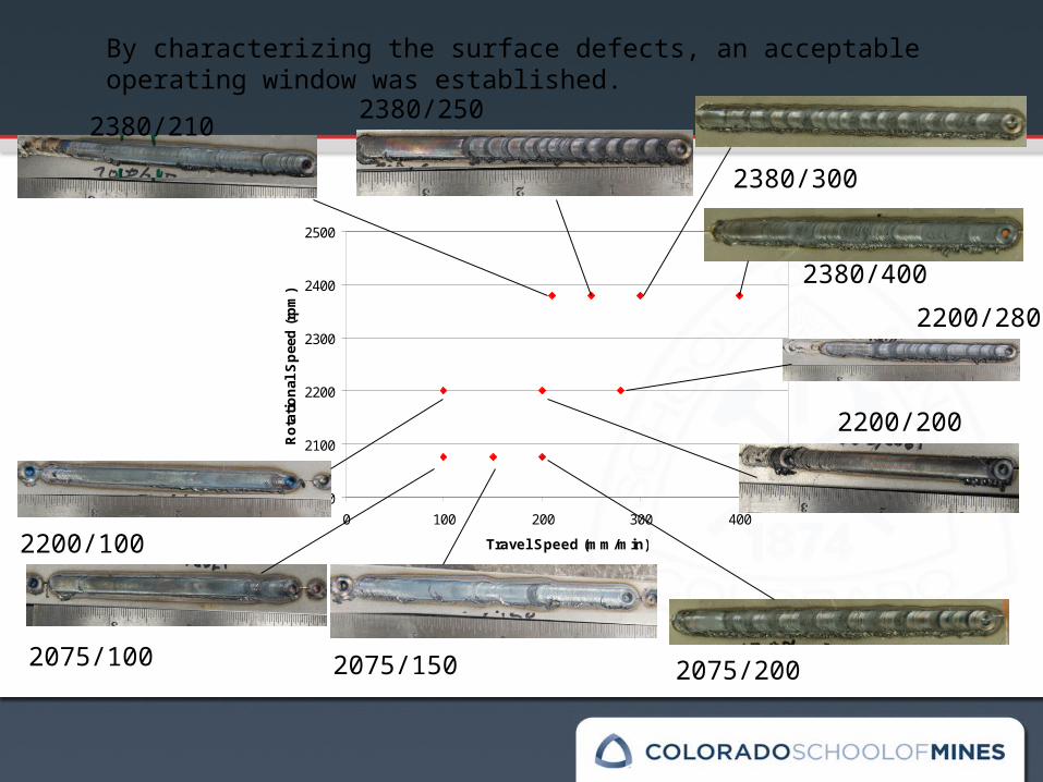
2200/200
2200/280
2200/100
2075/1502075/100
2380/2102380/250
2075/200
2380/300
2380/400
By characterizing the surface defects, an acceptable operating window was established.
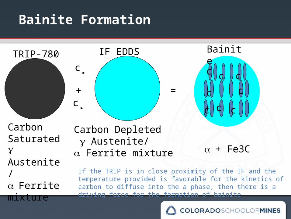
Carbon Saturated Austenite/ Ferrite mixture
Carbon Depleted Austenite/ Ferrite mixture
TRIP-780 IF EDDS
+ =
Bainite
If the TRIP is in close proximity of the IF and the temperature provided is favorable for the kinetics of carbon to diffuse into the a phase, then there is a driving force for the formation of bainite
Bainite Formation
+ Fe3C
c
c
c c
cc
c
cc
c
Future Work
‣Examine end microstructures using process parameters within the phase field
‣Examine process parameters bordering phase boundary for other alloy systems for welding of single crystal components, e.g. Ni super alloy turbine blades