Embed Size (px)
Citation preview

CURENT Seminar Series
The University of Tennessee, Knoxville, August 22nd 2017
Prof. Luigi Vanfretti
Rensselaer Polytechnic Institute, ECSE, Troy, NY
Web: ALSETLab.com
Email: [email protected] - [email protected]
Dr. Phillip Top
Lawrence Livermore National Lab
Web: https://software.llnl.gov
Email: [email protected]
OpenIPSL
Modeling and Simulation of Electrical Power Systems using
OpenIPSL.org and GridDyn

Agenda
• About Me (Luigi)
• My Research.
• Recruiting for: ALSETLab
• Part 1: (Luigi Vanfretti) Introduction:
Modeling and Simulation Generalities and Modelica
The OpenIPSL
Recent developments
• Part 2: (Phillip Top) Applications of the OpenIPSL library
and the FMI in GRIDDYN
• Latter today: Tutorial: (Me + You!)
Hands-on-Tutorial:
Overview of the OpenIPSL library
Overview of the OpenModelica environment
Hans-on-Example
Do the “preparatory work” so that everything is ready to go in your computer!
2

About Me - http://ALSETLab.com - Dr. Luigi!
3
Other facts and numbers:- Guatemalan and Italian Citizenships.- Speak/write Spanish (native), English, Italian (spoken, poorly written), Norwegian (Basic)- 36 years, married (March 4th, 2017) - no kids yet… but really want a dog!- Close family, brother and wife, live in Woodstock, NY; run Dolce Caffe in Kingston’s Historical Roundout- Lived in 4 countries, worked in 5…
2016 - 2017Consultant.
2000 – 2005. 5 year Electrical Power Engineering program @ Universidad de San Carlos de Guatemala.
YOB. 1981Guatemala
Visiting Researcher @ The University of Glasgow, Scotland
2006 – 2009MSc and PhD @ RPI
2010Post-Doc @ RPI
Fall 2004Intern at INDE (National Electrification Institute), Substations Engineering
2010 – 2017, KTH Royal Inst. Of Tech., Stockholm, Sweden2010: Associate Professor2012: Docent (Habilitation)2013: Associate Professor (‘tenured’)
2011 – 2017, SmarTS Lab. Research Group
2011 -External Scientific Advisor
(Consultant)2011 – 2016Special AdvisorR&D Division
All @ Statnett SF, Oslo, Norway (Power System Operator)

My Research – Cyber-Physical Power Systems
44
Implementation &Rapid Prototyping(software-in-the-loop real-time simulation)
Implementation &Testing
(hardware-in-the-loop real-time simulation)
System Performance(deployment and
demonstration)Validation
Verification
Testing
Testing Against Use Cases
Testing with other elements and within the environment
Testing each component in isolation and
with other elements
Unit Design
Models
Units
(SW, HW, Data)
Component
Design Models
Components
(SW, HW, Data)
Device Models Subsystems
Overall System
Models (incl.
grid)
User
Requirements &
Models
Operational
System
User Cases and Requirements(HLA Design using UML Spec and CIM)
System LevelDesign & Specifications(physical modeling andoff-line simulation)
Implementation(Production Code
Generation)
Integrated
SystemsSubsystem
Integration & Tests(hardware-in-the-loop
real-time simulation)
Model-and-Measurement-Based Systems Engineering of Power System and Synchrophasor Technologies

Recruiting @ ALSETLab
• I’m looking for graduate students to join my team!
• If you know someone that would be interested, please tell them to
check my website
• See: http://ALSETLab.com
5

New Course! Spring 2018 - CPS Modeling, Simulation and Analysis
• Understand cyber-physical systems and
how to model them.
• Lean about standardized modeling
languages and compliant tools
• Learn and become proficient with the
Modelica language
• Learn and apply model-based systems
engineering concepts and tools (UML,
SysML using Papyrus RT)
• Apply identification, control and
optimization techniques to CPS systems
• Apply its use for analysis of:
Power systems
Energy efficient building automation
Multi-domain energy systems
Cyber-physical systems design and
analysis 6

Modeling and Simulation of Electrical Power Systems using
OpenIPSL.org and OpenModelica.org
Part 1: Introduction
Prof. Luigi Vanfretti
Rensselaer Polytechnic Institute, ECSE, Troy, NY
Web: ALSETLab.com

Outline
o The role of models and simulation Generalities
In power electrical systems
o Modelica and power systems
o The OpenIPSL Project
o The OpenIPSL Library
o Continuous Integration
o On-going developments
8

A Fundamental Question: Why do we develop models and perform simulations?
• To reduce the lifetime cost of a
system
In requirements: trade-off studies
In test and design: fewer proto-types
In training: avoid accidents
In operation: anticipate problems!
Crucial for electrical power systems!
• The prospective pilot sat in the top
section of this device and was required to line up a reference bar with the
horizon. 1910.
• More than half the pilots who died in
WW1 were killed in training.
9

A Failure to Anticipate Huge Costs!
10
Others: WECC 1996 Break-up, European Blackout (4-Nov.-2006), London (28-Aug-2003), Italy (28-Sep.-2003), Denmark/Sweden (23-Sep.-2003)
Failure!
Existing modeling and
simulation (and associated)
tools were unable to
predict this (and other)
events.
There are many examples of failures to anticipate problems in power system operation!

The Multiple Roles of Modeling and Simulation in building:
Complex Cyber-Physical ”Systems-of-Systems”
11
Large Number of Vendors for the Final System
A Flying Micro-Grid!
M&S used to test prototypes in variety of
environments.
M&S are used to train users in the operational environment –
enhancing learning.Simulation costs 1/10 of running actual scenarios.
Scale of networks: cost-prohibitive or technically impossible for field tests.
M&S used to test and validate networking
protocols in laboratory -environment acting as a test
bed.

The Multiple Roles of Modeling and Simulation to develop
Cyber-Physical Power Systems (aka ‘smart grids’)
12
Implementation &Rapid Prototyping(software-in-the-loop real-time simulation)
Implementation &Testing
(hardware-in-the-loop real-time simulation)
System Performance(deployment and
demonstration)Validation
Verification
Testing
Testing Against Use Cases
Testing with other elements and within the environment
Testing each component in isolation and
with other elements
Unit Design
Models
Units
(SW, HW, Data)
Component
Design Models
Components
(SW, HW, Data)
Device Models Subsystems
Overall System
Models (incl.
grid)
User
Requirements &
Models
Operational
System
User Cases and Requirements(HLA Design using UML Spec and CIM)
System LevelDesign & Specifications(physical modeling andoff-line simulation)
Implementation(Production Code
Generation)
Integrated
SystemsSubsystem
Integration & Tests(hardware-in-the-loop
real-time simulation)
Conceptual Application for the Development of a WT Synchro phasor-Based Controller
Are today’s power system modeling and simulation approaches/tools fit to meet the
challenges of the cyber-physical world?
Dangers of Models and Simulation
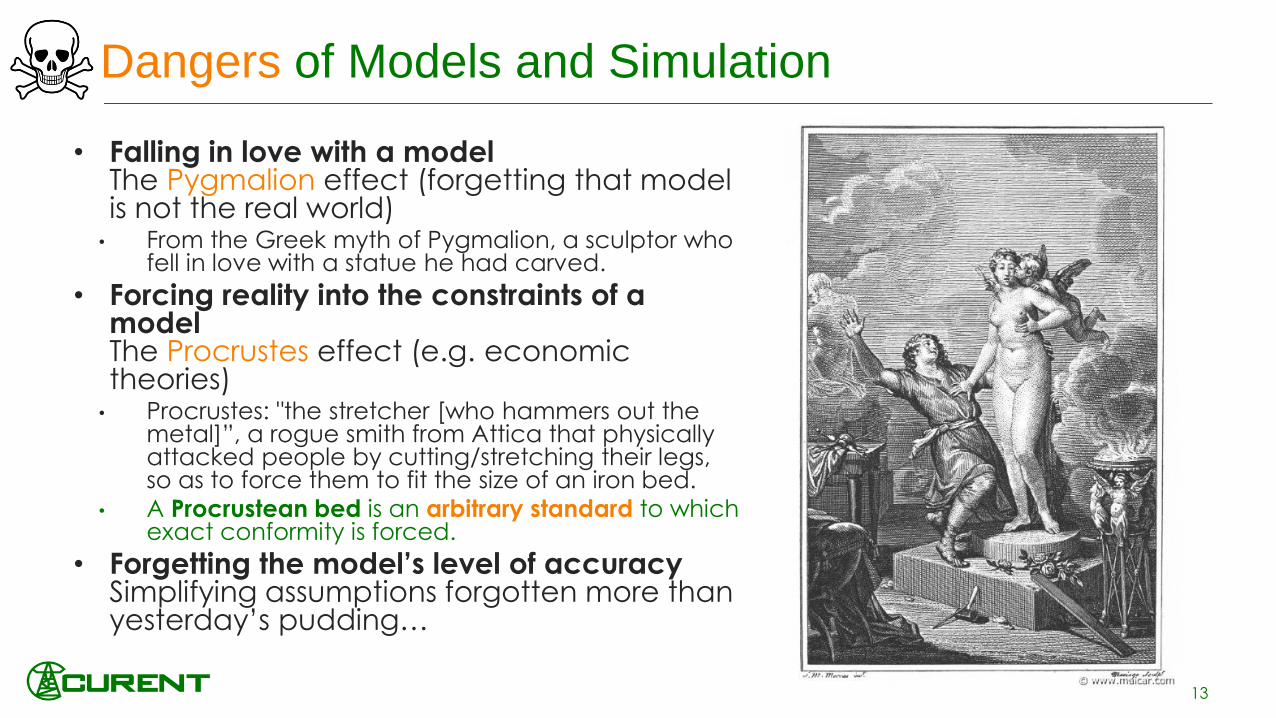
• Falling in love with a modelThe Pygmalion effect (forgetting that model is not the real world)
• From the Greek myth of Pygmalion, a sculptor who fell in love with a statue he had carved.
• Forcing reality into the constraints of a modelThe Procrustes effect (e.g. economic theories)
• Procrustes: "the stretcher [who hammers out the metal]”, a rogue smith from Attica that physically attacked people by cutting/stretching their legs, so as to force them to fit the size of an iron bed.
• A Procrustean bed is an arbitrary standard to which exact conformity is forced.
• Forgetting the model’s level of accuracySimplifying assumptions forgotten more than yesterday’s pudding…
13

Power system dynamics challenges for simulation
the tyranny of multiple time-scales
14
10-7 10-6 10-5 10-4 10-3 10-2 10-1 1 10 102 103 104
Lightning
Line switching
SubSynchronous Resonances, transformer
energizations…
Transient stability
Long term dynamics
Daily load following
seconds
Electromechanical Transients
Electromagnetic Transients
Quasi-Steady State
Dynamics
Models are simplified (averaged) to
allow for simulation of very large
networks.
Ad-hoc solvers have been developed
to reduce simulation time, but usually
the “model” is “interlaced” with the
solver (inline integration)
Generally there are no discrete events.
(Ad-hoc DAE solvers)
This is usually deal with by
discretizing the model and to solve it using discrete solvers.
The presence of large time constants and small time
constants and large amount of discrete switches.
Difficult to simulate very large networks (in the past?)
The models are simplified further by neglecting
most dynamics (replacing most differential
equations by algebraic equations).
(Ad-hoc DAE solvers)

Power System Phenomena Modeled and Discussed from this point on:power system electromechanical dynamics
15
10-7 10-6 10-5 10-4 10-3 10-2 10-1 1 10 102 103 104
Lightning
Line switching
SubSynchronous Resonances, transformer
energizations…
Transient stability
Long term dynamics
Daily load following
seconds
Electromechanical Transients
Electromagnetic Transients
Quasi-Steady State
Dynamics
Positive Sequence / RMS / or
Phasor Time-Domain
Simulation

Electromechanical Dynamics in the Western US (1996)
• What was measured: • What was simulated:
16
2 3 4 5 6 7 8 9-2
-1.5
-1
-0.5
0
0.5
1
P
(pu)
Time (sec)
Measured Response
Model Response
Electromechanical dynamic modeling help to capture ”wide-area” behavior across
geographical sparse interconnected networks such as these type of oscillations.
Good models are crucial for planning and operation of electrical power networks.
Before
Model
Calibration
After Model
Calibration

Power Systems General DAE Model
17[Ref.] F. Milano, Power System Modeling and Scripting, Springer, 2010.
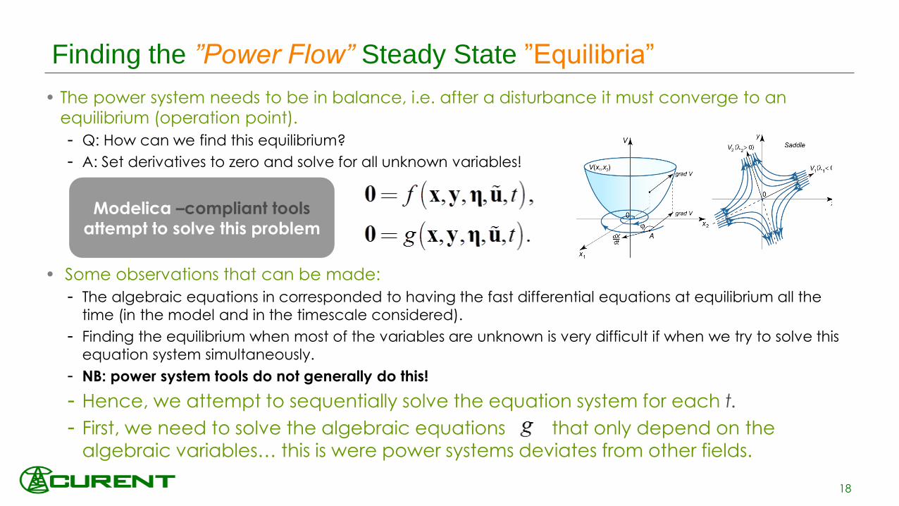
• The power system needs to be in balance, i.e. after a disturbance it must converge to an
equilibrium (operation point).
- Q: How can we find this equilibrium?
- A: Set derivatives to zero and solve for all unknown variables!
• Some observations that can be made:
- The algebraic equations in corresponded to having the fast differential equations at equilibrium all the
time (in the model and in the timescale considered).
- Finding the equilibrium when most of the variables are unknown is very difficult if when we try to solve this
equation system simultaneously.
- NB: power system tools do not generally do this!
- Hence, we attempt to sequentially solve the equation system for each t.
- First, we need to solve the algebraic equations that only depend on the
algebraic variables… this is were power systems deviates from other fields.
Finding the ”Power Flow” Steady State ”Equilibria”
18
Modelica –compliant tools
attempt to solve this problem

• Equation set g is separated in two sets of
algebraic equations:
(1) Is the part which governs how dynamic models will evolve, since they depend on
both x and y , e.g. generators and their control systems.
(2) Is the network model, consisting of transmission lines and other passive components
which only depends on algebraic variables, y.
Simulation: Starting from a solution of (2) only, equations (1) are solved at equilibrium individually; to compute the starting guess of an ad-hoc DAE solver that iterates for (1)-
(2) at each time step.
Power System Modeling and Simulation Approach
19

Hypotheses & Simplifications
Physical
System
Models
Equations
Analytical
Methods
Analyses
SpecializedM&S
Platform
Physical
System
User Defined
Models in Platform
Specific Language
Models with
Fixed
Equations
Available
(Limited)
Numerical
Algorithms
Analyses
Numerical Methods
Fundamental Implications of the Conventional Power Systems Approach
20
Hypotheses(assumptions)
Simplifications(approximations)
General Approach Power Systems Approach
Closed-FormSolution
NumericalSolution
User: Modeler and
Analyst Duality
Specialized Modeler Familiar with the Domain Specific Platform
Specialized AnalystFamiliar with the Domain
Specific Platform
Fixed Model is ”interlaced” with
one specific solver

Practical Implications of the Conventional Power Systems Approach
21
10-7 10-6 10-5 10-4 10-3 10-2 10-1 1 10 102 103 104
Lightning
Line switching
SubSynchronous
Resonances, transformer
energizations…
Transient stability
Long term dynamics
Daily load
following
seconds
Phasor Time-
Domain Simulation
PSS/EStatus Quo:Multiple simulation tools, with their own
interpretation of different model features and
data “format”.
Implications of the Status Quo:
- Dynamic models can rarely be shared in a
straightforward manner without loss of
information on power system dynamics.
- Simulations are inconsistent without drastic
and specialized human intervention.
Beyond general descriptions and parameter
values, a common and unified modeling
language would require a formal mathematical
description of the models – but this is not the
practice to date.

Why open standard-based modeling languages?
• Modeling tools first gained
adoption as engineers looked for
ways to simplify SW development
and documentation.
• Today’s modeling tools and their
use cases have evolved.
• Now: need for addressing bothsystem level design and SW
development/construction.
22
(2015)

Why equation-based modeling?
Equation—based modeling:
• Defines an implicit (not explicit) relation between variables.
• The data-flow between variables is defined right before simulation of the
model (not during the modelling process!)
• A system can be seen as a complete model or a set of individual
components.
• The user is (in principle) only concerned with the model creation,
and does not have to deal with the underlying simulation engine
(only if desired).
• It also allows decomposing complex systems into simple sub-
models easier to understand, share and reuse
23
CSSL (1967) introduced a
special form of “equation”:
variable = expression
v = INTEG(F)/m
Programming languages usually
do not allow equations!

Graphical Equation-Based Modeling
• Each icon represents a physical
component (i.e. a generator, wind
turbine, etc.)
• Composition lines represent the actual
interconnections between components
(e.g. generator to transformer to line to …)
• Physical behavior of each component is
described by equations.
• There is a hierarchical decomposition of
each component.
24

Key: standardized and open language specification
is a (computer) modeling language, it is not a tool!
• Modelica is a free/libre object-oriented
modeling language with a textual definition to
describe physical systems using differential,
algebraic and discrete equations.
• A Modelica modeling environment is needed to
edit or to browse a Modelica model graphically
in form of a composition diagram (= schematic).
• A Modelica translator is needed to transform a
Modelica model into a form (usually C-code)
which can be simulated by standard tools.
• A Modelica modeling and simulation
environment provides both of the functionalities
above, in addition to auxiliary features (e.g.
plotting)
25
http://modelica.readthedocs.io/en/latest/#

modeling and simulation environment (tool) tasks
26
Modelica Model
Flat model
Hybrid DAE
Sorted equations
C Code
Executable
Optimized sorted
equations
Modelica
Model
Modelica Graphical Editor
Modelica
Source code
Translator
Analyzer
Optimizer
Code generator
C Compiler
Simulation
Modelica Textual Editor
Frontend
Backend
"Middle-end"
Modeling
Environment

Acasual Modeling and it’s Implications on Model/Tool Development
• Acasual Modeling implicitly leads to faster
development and lower maintenance for models
(and even tools)
• The acausality makes Modelica library classes more
reusable than traditional classes containing
assignment statements where the input-output
causality is fixed.
• Modelica Compiler performs Causalization
o It flattens the model and then transform and
sort all equations that give the model
description.
o Aim is to match each equation to a variable,
hence the term “matching” process, doing an
Index reduction of the DAEs and transform
them to ODEs
27
Approach used by Modelica Tools
Approach used by Power
System Tools
User Defined Models
in some PS Tools and
Generic Tools
(Simulink)

Present Modeling
and Simulation
issues
Causal Modeling
Model
Exchange
Inconsis-
tency
Modeling limitations
• The order of computations is decided at
modelling time
• Models are black boxes whose parameters are
shared in a specific “data format”
• For large models this requires translation into theinternal data format of each program
• There is no guarantee that the samestandardized model is implemented in the same
way across different tools
• Even in Common Information Model (CIM) v15,
only block diagrams are provided instead ofequations
• Most tools make no difference between “solver”
and “model” – in many cases solver is implantedin the model
Acausal Causal
R*I = v; i := v/R;
v := R*i;
R := v/i;
Why for power systems?
28

• Previous and Related Efforts
o Modelica for power systems was first attempted in the early 2000’s (Wiesmann & Bachmann, Modelica 2000) -“electro-magnetic transient (EMT) modeling” approach.
SPOT (Weissman, EPL-Modelon) and its close relative PowerSystems (Franke, 2014); supports multiple modelingapproaches –i.e. 3phase, steady-state, “transient stability”, etc.
o Electro-mechanical modeling or “transient stability” modeling:
Involves electro-mechanical dynamics, and neglects (very) fast transients
For system-wide analysis, easier to simulate/analyze - domain specific tools approach
o ObjectStab (Larsson, 2002; Winkler, 2015) adopts ”transient stability” modeling.
o The PEGASE EU project (2011) developed a small library of components in Scilab, which where ported to properModelica in the FP7 iTesla project (2012-2016).
o The iPSL - iTesla Power Systems Library (Vanfretti et al, Modelica 2014, SoftwareX 2016), was released during 2015.Most models validated against typical power system tools.
o F. Casella (OpenModelica 2016, Modelica 2017) presents the challenges of dealing with large power networksusing Modelica, and a dedicated library to investigate them using the Open Modelica compiler.
OpenIPSL takes iPSL as a starting point and moves it forward (this presentation).
and Power Systems
29

(3) Decrease of avoidance forces• SW-to-SW validation gives quantitatively an
similar answer than domain specific tools.
• Accuracy (w.r.t. to de facto tools) moreimportant than performance
and Power Systems
Why another library for power systems?
Social Aspects (Vanfretti et al, Modelica 2014)
• Resistance to change: an irrational and dysfunctional reaction of users (and developers?)
o Users of conventional power system tools are skeptical about any other tools different to the one they use (or develop), and are averse about new technologies (slow on the uptake)
• Change agents contribute (+/-) to address resistance through actions and interactions.
30
A never-ending effort!• The library has served to bridge the gap
between the Modelica and power systemscommunity by:
• Addressing resistance to change (see above)
• Interacting with both communities – differentlevels of success…
(2) Proposea common human and computer-readable mathematical “description”: use of Modelica for unambiguous model exchange.
(1) Strategy do not impose the use of a specific simulation environment (software tool), instead,

The OpenIPSL Project
• http://openipsl.org
• Built using the Modelica
language:
• Distributed with the MPL2
license:
31
Free as in Puppy!
Needs a lot of your love and care to grow and be happy!

• KTH SmarTS Lab (my former research team) actively participated in the group or partners developing iPSL until the end of the iTesla project (March 2016)
• iPSL is a nice prototype, but we identified the following issues:o Development: Need for compatibility with OpenModelica, (better) use of object
orientation and proper use of the Modelica language features.
o Maintenance: Poor harmonization, lack of code factorization, etc.
o Human issues: The development workflow was complex Different parties with disparate objectives, levels of knowledge, philosophy, etc.
• OpenIPSL started as a fork of iPSL in 2016, and has now largely evolved!• OpenIPSL is hosted on GitHub at http://openipsl.org
• OpenIPSL is actively developed by ALSETLab (formerly SmarTS Lab) members and friends, as a research and education oriented library for power systems it is ok to try things out !
New research requirements and the experiences from previous effort indicated:
- a clear need for a different development approach –
one that should address a complex development & maintenance workflow!
The OpenIPSL Project - Origins
32
Fork: copy of a project going in a different development direction

The OpenIPSL Library – Key Feautures
OpenIPSL is an open-source Modelica library
for power systems
• It contains a set of power system
components for phasor time domainmodeling and simulation
• Models have been validated against a
number of reference tools (mainly PSS/E)
OpenIPSL enables:
• Unambiguous model exchange
• Formal mathematical description of models
• Separation of models from tools/IDEs and solvers
• Use of object-oriented paradigms
33

The OpenIPSL Library – WT Example
34

The OpenIPSL Library – Network Example
35
Resulting Parameter Declaration
Resulting Class Instantiation
Class Connections

Many Application Examples Developed!!!
The OpenIPSL Library – Application Examples
36
Klein-Rogers-Kundur 2-Area 4-Machine System
IEEE 9 Bus IEEE 14 Bus
Namsskogan Distribution Network

The OpenIPSL Library – providing a good “initial guess”
• An initial guess for all algebraic, continuous and discrete variables need to be provided to solve a numerical problem!
• When solving differential equations, one needs to provide the initial value of the state variables at rest.
• In Modelica, initial values can be either solved or specified in many ways, we use the following
• Using the ”initial equation” construct:
initial equation
• x = some_value OR x = expression to solve
• Setting the (fixed=true, start=x0) attribute when instantiating a model when the start value is known (or possible to calculate)
• If nothing is specified, set the default would be a guess value (start= 0, fixed=false).
• In the OpenIPSL models we do the following:
• The initial guess value is set with (fixed = false) for initialization.
• Model attributes are treated as parameters with value (fixed = true),
37
• In OpenIPSL we use a power flow
solution from an external tool (e.g.
PSAT or PSS/E) as a starting point
to compute initial guess values
through parameters within each
model.
• The power flow solution is NOT
the initial guess value itself.
• Aim is to provide a better
“initial guess” to find the initial
values of the DAE system.

Third order
model from
PSAT
implemented in
OpenIPSL
The OpenIPSL Library – “initial guess” example
38

The OpenIPSL Project Documentation
• Documentation of the code changes:
• Explicit messages in commits
and pull-requests
• Documentation of the project
Presentation
User guide
Dev. guidelines & How to contribute
The documentation is written in
reStructuredText (reST) hosted on
http://openipsl.readthedocs.io/
• Note: Model documentation is not included,
users are referred to literature, textbooks and
the proprietary documentations.
39

The OpenIPSL’s Project - Continuous Integration (CI) Service
40
• A CI service was implemented and integrated to the repository. The Modelica
support was achieved with the following architecture:
• Travis as CI service provider
• Docker as the “virtualization” architecture
• DockerHub to host a Docker image with Python & OpenModelica
• The CI performs automated syntax checks on the library.
New changes
are submitted as
a new pull
request to the
master branch
The pull request
triggers the
Travis CI
The tailored
Docker image
is pulledThe reference
traces are
pulled from a
dedicated
server
The latest version of
the library containing
the changes is pulled
from GitHub
The Docker is
instantiated to
create a
replicable
environment
where the tests
are carried out
The pass / fail
flag from the
tests on Travis is
sent to Github

Go to the OpenIPSL Github repo https://github.com/openipsl , see runTest.py
The OpenIPSL’s CI Commit Output (Syntax Check Workflow)
41
Click to see the IO from Travis
Results from CI testing on
syntax check on several
“Application Examples”

•OpenIPSL.org organization in Github! (Prof. Dietmar Winkler)•Website will be also hosted there!
The OpenIPSL – Ongoing Developments and Future Work!
• Library Improvements (Tin Rabuzin, Maxime Baudette)
• 100% Compatibility with OM (100% Syntax Check, ~100%
Simulation for components) through efforts in Continuous
Integration adoption
• Change in the models to include inheritance (code factorizing)
• Fixing and validating network models – application examples
(thanks to CI)
• ENTSO-E IOP Models (Francisco Gomez Lopez)
• Proof of concept and test model
• Excitation system and small network model
42

The OpenIPSL – Ongoing Developments and Future Work!
• Efforts within the openCPS project
• New Component Models• New components for the OpenIPSL being developled:
• Process noise (stochastic) pdf-based load models
• Frequency estimation models
• PMU “Container” Block (frequency estimation + packaging)
• Control systems for islanded operation and automated resynch
• Multi-domain modeling for gas turbines and power systems• Based on ThermoPower and OpenIPSL
• Miguel Aguilera, et al.
• More!
• Joint modeling and simulation of transmission (positive sequence) and distribution (three-phase) power networks
• Marcelo de Castro Fernandez and Prof. Janaina Gonçalvez (UFJF, Brazil)
43

The OpenIPSL – Ongoing Developments (CI+R)
• CI + Regression Testing
• A two-stage process
o Modelica syntax check
(against Modelica
language implementation in OM)
o Model validation check
(against reference
simulation results of
“trusted” model)
• Fully automated through online
CI services
• Diagnostic help to the
developers to locate the error!
44
Prototype Implementation in the “modelValidation-CI” branch

The OpenIPSL – Ongoing Developments (CI+R)
45
OR
Syntax Error
Model Error
Merging Blocked
All OK !Merging
Allowed

Multi-domain modeling for gas turbines and power systems
46
OpenIPSL
OpenIPSL
ThermoPower
Interface!
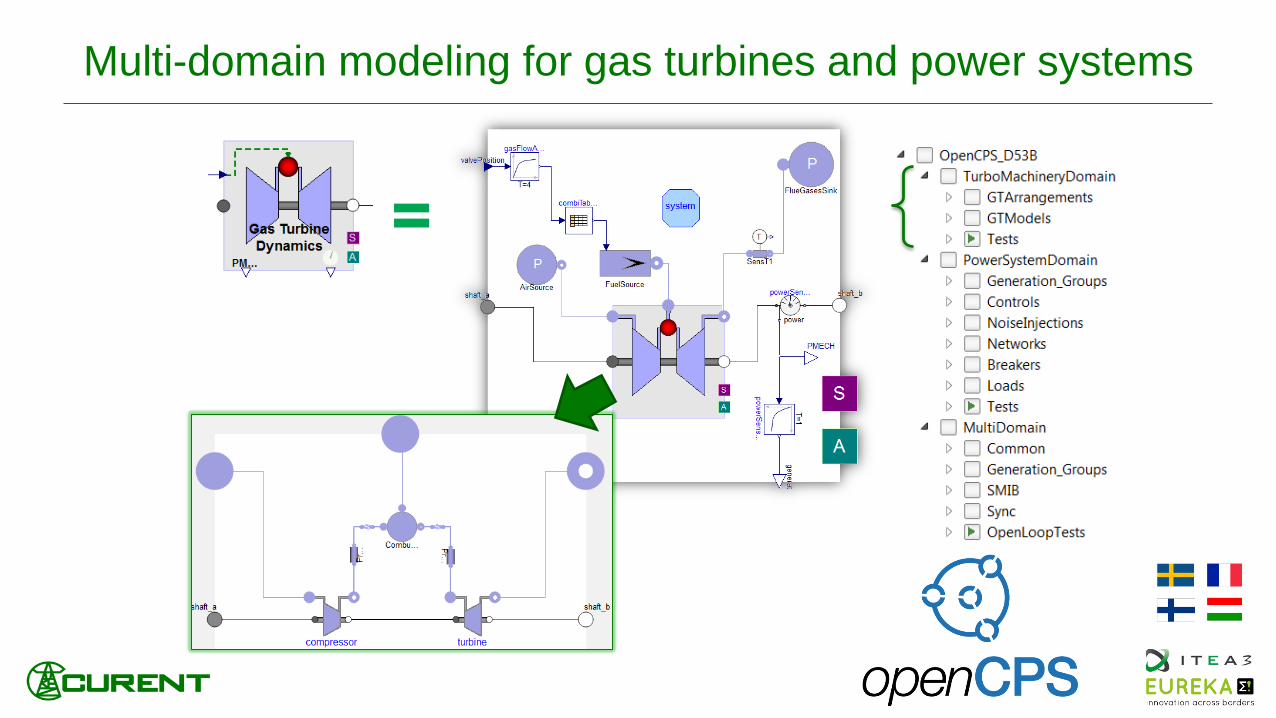
Multi-domain modeling for gas turbines and power systems
47
=

Stochastic Load Model and Influence in
Single-Domain and Multi-Domain Model Response
Load varies d_P in the time interval
between t1 and t1+d_t.
Noise model can be added as real input u.
Noise Model
• Expectation value
• Standard deviation
• Sample Period
Sine wave or ramp containing
the noise can be used to model
the “normal” load variation
Mechanical Power

Joint modeling and simulation of transmission and
distribution power networks
• Work together with Marcelo de Castro
Fernandez , Prof. Janaina Gonçalvez (UFJF,
Brazil) and Maxime Baudette
• Hybrid single-phase three- phase model for
power flow simulation using Modelica as
modeling language. The formulation of such
model was proposed by Jose Mauro Marinho
and Glauco Nery Taranto in the paper:• [ref]Jose Mauro T. Marinho and Glauco Nery Taranto. A Hybrid
Three-Phase Single-Phase Power Flow Formulation Published in: IEEE Transactions on Power Systems (Volume: 23, Pages: 1063:1070, Issue: 3, Aug. 2008)
49

Implementation of DigSilentPowerFactory
Component Models
MSc Thesis work by Harish Krishnappa
IEPG, TU Delft
• Models include:
o Synchronous Gen.
o Loads
o Transformer
o Transmission Line
o Exciter
o OEL
o Speed governor
o Steam turbine
o OLTC
o Induction motor
50

51
Luigi Vanfretti Tin RabuzinAchour
Amazouz
Mohammed
Ahsan Adib
Murad
Francisco
José Gómez
Jan Lavenius Le Qi Maxime
BaudetteMengjia
ZhangTetiana
Bogodorova
Giusseppe
Laera
Joan Russiñol
Mussons
The OpenIPSL can be found online• http://openipsl.org
RaPId, a system identification software that uses OpenIPSL can
be found at:
• https://github.com/ALSETLab/RaPId
• http://dx.doi.org/10.1016/j.softx.2016.07.004
Thanks to all my current and
former students, friends and
developers that have supported
the effort!
Our work on OpenIPSL has been published in the
SoftwareX Journal:
• http://dx.doi.org/10.1016/j.softx.2016.05.001
Marcelo
Castro
Miguel
Aguilera

Part 2: (Phillip Top)Applications of the OpenIPSL library
and the FMI in GRIDDYN
52