Embed Size (px)
Citation preview

FOX Cultivator
Instruction Manual
MANU-2530-ING Rev. C


STARA S.A. - THE AGRICULTURAL MACHINERY AND IMPLEMENTS COMPANYCNPJ: 91.495.499/0001-00
AV. STARA, 519 Não-Me-Toque/RS - Brazil
CEP 99470-000 Telephone/Fax: +55 54 3332-2800
e-mail: [email protected] page: www.stara.com.br
October/2014 - Revision CMANU-2530-ING
FOX CULTIVATOR
INSTRUCTION MANUAL

CONTEúDO
1 - MAIN COMPONENTS ....................................................................................................................7
2 - IDENTIFICATION ...........................................................................................................................8
3 - TECHNICAL SPECIFICATIONS ....................................................................................................8
4 - SAFETY STANDARDS ..................................................................................................................9
4.1 - Review all safety information ........................................................................................... 9
4.2 - Follow all safety instructions ............................................................................................ 9
4.3 - Use of intent ..................................................................................................................... 9
4.4 - Improper operation ......................................................................................................... 10
4.5 - Safely operating and transporting the implement........................................................... 10
4.6 - Transporting the implement on trucks ............................................................................ 12
4.7 - Caution while on steep terrain........................................................................................ 12
4.8 - Work in well ventilated areas ......................................................................................... 12
4.9 - Avoid heating parts near fluid lines ................................................................................ 12
4.10 - Avoid fluids under high pressure .................................................................................. 13
4.11 - Emergency procedures ................................................................................................ 13
4.12 - Tire safety procedure .................................................................................................. 13
5 - ASSEMBLY ..................................................................................................................................14
6 - OPERATION INSTRUCTIONS ....................................................................................................19
6.1 - Tractor preparation ......................................................................................................... 19
6.2 - Cultivator adjustments.................................................................................................... 19
6.2.1 - Row spacing ............................................................................................................ 19
6.2.2 - Working depth ......................................................................................................... 20
6.2.3 - Leveling .................................................................................................................. 20
6.2.4 - Shank auto-release mechanism adjustment ........................................................... 20
6.2.5 - Leveling roller, operations and adjustments ............................................................ 21
6.2.6 - Disk blade adjustments ........................................................................................... 21
6.2.6.1 - Spring tension adjustments ............................................................................ 22
6.2.6.2 - Furrow depth adjustment ................................................................................ 22
6.2.7 - Disk side adjustments ............................................................................................. 23
6.3 - Tractor hook-up .............................................................................................................. 23
7 - MAINTENANCE ...........................................................................................................................24
8 - OPERATION ................................................................................................................................25
8.1 - Shank auto-release system............................................................................................ 25
8.2 - How to use the cultivator ................................................................................................ 26

9 - TROUBLESHOOTING SHANKS .................................................................................................27
10 - TROUBLESHOOTING HYDRAULICS .......................................................................................28
WARRANTY CLAIMS ........................................................................................................................29
WARRANTY FORFEITURE ..............................................................................................................31
WARRANTY CERTIFICATE ..............................................................................................................33
TECHNICAL DELIVERY TERMS ......................................................................................................35
TECHNICAL CHECK-UP ...................................................................................................................43
INTRODUCTION
Dear client, you have just become the proud owner of an implement made with the highest level of technologies, while having the direct involvement of rural producers in its development.
The Fox field cultivator’s primary function is to till compact farming soils to the depth of 26 cm, in no-till areas with diverse annual commodities. Thus, this implement has certain specific constructive characteristics, additionally the residue tillage is done by using offset disk blades, with ample spacing to allow for the easy passage of stubble residue, also offset shanks spaced every 30 cm, and having a thin wall thickness (31 mm), its main objective being that of not disturbing the soil while preserving the ground coverage, which protects the soil from the solar radiation and rain damage.
Thus, this soil preparation makes provisions for the next crop, the Fox cultivator comes with ground leveling roller baskets, which are found directly behind the ripper shanks, in order to reduce excessive ground tillage, short ripper points were developed in a such a way that, when ripping compacted soil they are positioned below the ground surface, thus preserving the top soil stubble coverage.
The ripper shanks have an efficient automatic disarming system, which uses coil springs, besides the protection it offers the implement, and when spring tensions are properly adjusted, they offer an oscillating tiller, which amplify the compacted soil breaking capabilities between rows. The reduced spacing between ripper shanks, permits that the implement works at shallower depths while not minimizing the ground tillage quality, which demands less traction force and less fuel is consumed.
The Fox field cultivator has various gang versions of 7 to 15 shanks, thus requiring tractors with power requirements to suit the number of shanks, and as a rule of thumb when calculating for horsepower requirements use 10-15 hp/shank.
The Fox when being properly used and maintained, can have a long useful life, offering you a high yielding investment, while being very economic. For this reason we highly recommend that you carefully read the instruction manual, consulting its pages whenever a question arises. STARA also offers its technical assistance services to assist you, along with your local dealership, so that you can have the full yielding potential of your combination tiller.
This manual is available on our site www.stara.com.br, along with our full line of products.
Stara S.A.- The Agricultural Implements Company
Não-Me-Toque, RS, Brazil

Fox Instruction Manual 7
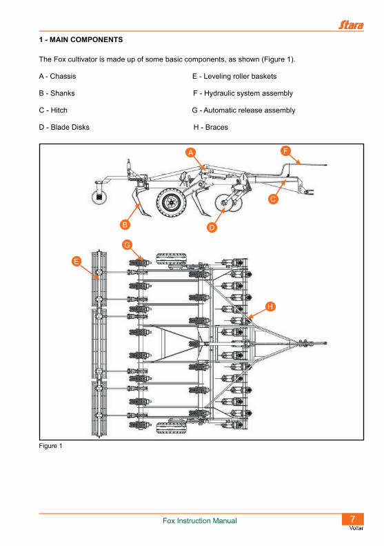
1 - MAIN COMPONENTS
The Fox cultivator is made up of some basic components, as shown (Figure 1).
A - Chassis E - Leveling roller baskets
B - Shanks F - Hydraulic system assembly
C - Hitch G - Automatic release assembly
D - Blade Disks H - Braces
Figure 1
E
H
C
D
F
B
A
G

8 Fox Instruction Manual
2 - IDENTIFICATION
All Stara implements have an identification plate, on it you will find the following, WEIGHT, CAPACITY, MODEL, MANUFACTURED DATE and the SERIAL Nº .
When requesting parts or dealing with your dealership, or even factory, supply this information and this will assist all in identifying your implement.
The identification plate (Figure 2) is mounted on the implement’s chassis.
3 - TECHNICAL SPECIFICATIONS
Version N° of shanks 7 9 11 13 15
Dimensions (m)
Width 2.51 2.92 3.66 4.12 5.00
Length 5.59
Height 1.34
Disks Ø 18” 7 9 11 13 15
Leveling rollersw/pointer 1 x 2 mm 2 x 1.4 m 1 x 1.8 m 2 x 2 m 2 x 1.4 m
w/o pointer - - 1 x 1.8 m - 1 x 1.80 m
Job width m 2.1 2.7 3.3 3.9 4.5
Job depth cm 18 - 26
Power hp 70 - 105 90 - 135 110 - 165 130 - 195 150 - 225
Weight kg 2100 2500 2950 3450 3850
Working speeds km/h 4 - 8
PaintPredominant color: green (chassis, hitch, cylinder support and drive-axle);Orange: Rims;Black: Disk blade support, disks, automatic disarm assembly, shanks and leveling roller baskets.
Table 1
Figure 2

Fox Instruction Manual 9
4 - SAFETY STANDARDS
4.1 - Review all safety information
This symbol is used as a warning sign (danger, warning and caution). Whey you see this sign on your implement be aware of possible hazards.
Follow all safety instructions and safety measures.
Displayed warning signs showing DANGER,CAUTION are usually located near danger areas.
The words DANGER/CAUTION are safety warnings in this manual.
4.2 - Follow all safety instructions
This implement follows design and work related SAFETY POLICIES FOR MACHINERY EQUIPMENT CONSTRUCTION per NR-12.
Carefully read all safety related messages and warnings in your manual (Figure 4).
• Maintain all safety decals in good condition, replacing all damaged or lost decals.
• When replacing decals, these can be found at your local Stara dealership.
• Learn how to properly operate your implement.
• Do not allow untrained personnel to operate the implement.
• Maintain your implement in good working condition.
• Changing the original design of the implement is not allowed, since any alterations could affect the operation of the implement, its safety and could reduce its lifespan.
Should you not fully understand any part of this manual and need the assistance of a technician, please contact your local Stara dealership.
4.3 - Use of intent
This implement was specifically designed for grains, seeds and fertilizers.
This implement should be driven and operated by a trained operator.
Figure 3
Figure 4
10 Fox Instruction Manual
4.4 - Improper operation
• Hitching-up, hooking-up or pushing other implements or
accessories is not allowed, except for Kits Ks (seed boxes).
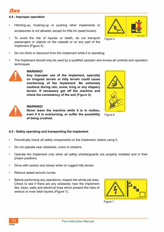
• To avoid the risk of injuries or death, do not transport passengers or objects on the catwalk or on any part of the implement (Figure 5).
• Do not climb or dismount from the implement while it is operating.
• The implement should only be used by a qualified operator who knows all controls and operation techniques.
WARNING!Any improper use of the implement, specially on irregular terrain or hilly terrain could cause overturning of the implement. Be extremely cautious during rain, snow, icing or any slippery terrain. If necessary get off the machine and check the consistency of the soil (Figure 6).
WARNING!Never leave the machine while it is in motion, even if it is overturning, or suffer the possibility of being crushed.
4.5 - Safely operating and transporting the implement
• Periodically check all safety components on the implement, before using it.
• Do not operate near obstacles, rivers or streams.
• Operate the implement only when all safety shields/guards are properly installed and in their proper positions.
• Drive with caution and slowly while on rugged hilly terrain.
• Reduce speed around curves.
• Before performing any operations, inspect the whole job area. Check to see if there are any obstacles near the implement like, trees, walls and electrical lines which present the risks of serious or even fatal injuries (Figure 7).
Figure 5
Figure 6
Figure 7

Fox Instruction Manual 11
• Maintain the tiller clean and free of oil or grease residues,which can cause accidents (Figure 8).
• The tiller has special characteristics like, being extra wide, which restricts its transit on public roadways or highways. If there is the need to travel on public roadways, consult with the local transit authorities and follow all regulatory and local laws.
• Verify that the implement is in proper working condition. Should there be any irregularities which could affect the operation of the implement, seek to have maintenance done prior to use or transport.
• Reduce speed while on wet or frozen floors, and on gravel covered terrain.
• Do not offer rides to hitchhikers.
• Do not operate the implement or any vehicle while drunk or under the influence of tranquilizers or stimulants.
• Before operating the implement, check for any persons or obstructions near the it (Figure 9) (Figure 10).
• Do not transport any passengers on the external part of the implement, doing so may cause grave injuries or even death (Figure 5).
• Stay clear of moving mechanical parts like springs, gears and chains (Figure 11) (Figure 12).
Figure 8
Figure 9 Figure 10 Figure 11
Figure 12
12 Fox Instruction Manual
4.6 - Transporting the implement on trucks
• Position the implement so that its components are not exposed outside the truck bed.
• Secure the wheels using blocks and chains tied-down to the truck bed.
• Lock-down the implement to the truck bed using the tires.
• Be aware of the implement dimensions. Be very cautions when traveling near trees, electrical lines and overpasses.
4.7 - Caution while on steep terrain
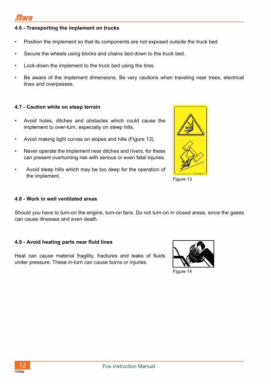
• Avoid holes, ditches and obstacles which could cause the implement to over-turn, especially on steep hills.
• Avoid making tight curves on slopes and hills (Figure 13).
• Never operate the implement near ditches and rivers, for these can present overturning risk with serious or even fatal injuries.
• Avoid steep hills which may be too deep for the operation of the implement.
4.8 - Work in well ventilated areas
Should you have to turn-on the engine, turn-on fans. Do not turn-on in closed areas, since the gases can cause illnesses and even death.
4.9 - Avoid heating parts near fluid lines
Heat can cause material fragility, fractures and leaks of fluids under pressure. These in-turn can cause burns or injuries.
Figure 13
Figure 14
Fox Instruction Manual 13
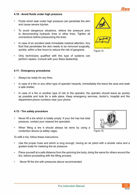
4.10 - Avoid fluids under high pressure
• Fluids which leak under high pressure can penetrate the skin and cause severe injuries.
• To avoid dangerous situations, relieve the pressure prior to disconnecting hydraulic lines or other lines. Tighten all connections before pressurizing the lines.
• In case of an accident seek immediate medical attention. Any fluid that penetrates the skin needs to be removed surgically, quickly, within a few hours to reduce the risk of gangrene.
• Only technicians qualified with this type of systems can perform repairs. Consult with your Stara dealership.
4.11 - Emergency procedures
• Always be ready for any fires.
• In case of a fire or any other type of operator hazards, immediately the leave the area and seek a safe shelter.
• In case of a fire or another type of risk to the operator, the operator should leave as quickly as possible and look for a safe place. Keep emergency services, doctor’s, hospital and fire department phone numbers near your phone.
4.12 - Tire safety procedure
• Never fill a tire which is totally empty. If your tire has lost total pressure, contact your nearest tire specialist.
• When filling a tire it should always be done by using a contention device (a safety cage).
To refill a tire, follow these instructions:
• Use the proper hose and which is long enough, having an air pistol with a double valve and a graded scale for metering the air pressure.
• Place yourself at a safe distance from the spinning tire body, doing the same for others around the tire, before proceeding with the filling process.
• Never fill the tire with pressures above recommended.
Figure 15
Figure 16

14 Fox Instruction Manual
5 - ASSEMBLY
The Fox cultivator leaves the factory with some of its sub-assemblies already assembled, but to facilitate shipping, a major portion of the larger assemblies will be assembled at the dealership or at the final destination.
To facilitate in the assembly process, a sequential order should be followed, as listed below:
• 1st - Mounting the shanks on the chassis.
Mount the shank on the base using the cotter-pin. To do so, use a hoist and place the chassis on saw-horses/stands, next, install the shank manually. The most practical way to install the shank is to firstly engage the roller onto the auto-release lever seating, then pull the shank until the holes lineup, next install the lock-pin.
• 2nd- Mounting wheels onto the axle (Figure 18).
Remove the wheel hub nuts, next center the tire on the bolts, making sure that the tire remains centered on the wheel hub. Replace the nuts until they snug-up to the rim. Tighten all the nuts until secured on the tire hub. Repeat these steps on the other side and then release the wheel arm braces on both sides so that it rides free.
Figure 17
LEVERBASE
ROLLER
SHANK
LOCK-PIN
Figure 18
BRACE MADE FOR HOLDING THE ARM.
NUT

Fox Instruction Manual 15
• 3rd. - Mounting the hitch to chassis (Figure 19).
Remove the hitch lock-pins, next place the hitch on the chassis and line-up the holes. Replace the lock-pins and install the cotter-pins.
Next install the stabilizer on the chassis, and line-up the hitch holes to the stabilizer replacing the lock-pins and the cotter-pins.
• 4th. - Installing the disk supports to the hitch.
Mount the disk supports “S” to the hitch, using four height adjustment pins “P”, keeping them at a horizontal position as shown on figure 20. To do this, select one of the adjustment holes on the support mounting plate (in most cases, the second hole from the bottom is generally used for most field conditions).
Note that the part of the support tube, where the staggered discs are mounted, these should remain behind the implement.
• 5th.- Installing the braces and lift cylinder supports.
1 - Fox 7 shanks: This model does not have any side braces, and the left & right lift cylinder supports are bolted on the front-side of the chassis, done through six bolts “F” for each support, as shown (Figure 21).
Figure 19
COTTER-PIN
COTTER-PIN
STABILIZER
HITCH
CHASSIS
LOCK-PIN
LOCK-PIN
Figure 20
HITCH
DISK SUPPORT “S”
PIN “P”
Figure 21
CHASSIS
CYLINDER SUPPORT
BOLTS “F”

16 Fox Instruction Manual
2 - Fox 9 & 11 shanks: These models also do not have lateral bracing, but the right and left cylinder supports are bolted to the chassis, as are the disc supports, using locking-pins “P” and bolts “F” (Figure 22).
3 - Fox 13 shanks: On this model, the side cylinder supports and the all-thread rods “T”, are used to join the chassis frame sides with the hitch frame. To facilitate the assembly, follow these steps:
a) Pass the all-thread rod “T” through the existing hole on the cylinder support (Figure 23).
NOTE!The braces are side specific to right and the left side of the implement.
b) Install one of the nuts “P” to the end of each all-thread rod, on the left or right side (Figure 24).
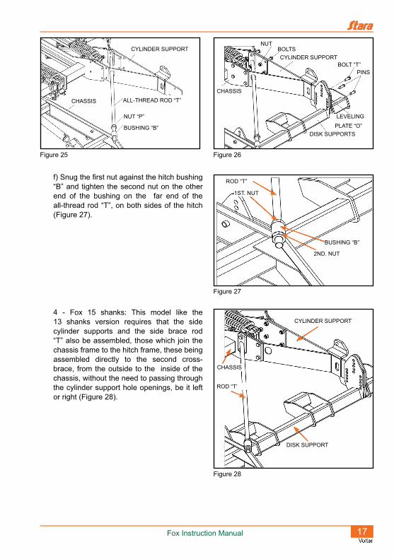
c) Place the all-thread rod with the cylinder support on the side of the hitch in such a way that part of the all-thread rod goes through the bushing “B” of the hitch (Figure 25).
d) Install the cylinder support nuts & bolts, along with the height adjustment pins on the disk support mounting plate “O”, maintaining equal adjustments with relation to the hitch (Figure 26).
e) Install the locking bolts “T”, on the 4 adjustment holes of the disk support, as shown on (Figure 26).
Figure 22
BOLT “F”
BOLTS “F”
CYLINDER SUPPORTLOCK-PINS “P”
DISK SUPPORT
Figure 23
CYLINDER SUPPORT
ALL-THREAD ROD “T”
Figure 24
CYLINDER SUPPORT
ALL-THREAD ROD “T”
NUT “P”
Fox Instruction Manual 17
f) Snug the first nut against the hitch bushing “B” and tighten the second nut on the other end of the bushing on the far end of the all-thread rod “T”, on both sides of the hitch (Figure 27).
4 - Fox 15 shanks: This model like the 13 shanks version requires that the side cylinder supports and the side brace rod “T” also be assembled, those which join the chassis frame to the hitch frame, these being assembled directly to the second cross-brace, from the outside to the inside of the chassis, without the need to passing through the cylinder support hole openings, be it left or right (Figure 28).
Figure 25
CYLINDER SUPPORT
CHASSIS ALL-THREAD ROD “T”
NUT “P”
BUSHING “B”
Figure 26
NUTBOLTSCYLINDER SUPPORT
BOLT “T”PINS
LEVELING
PLATE “O”DISK SUPPORTS
CHASSIS
Figure 27
ROD “T”
1ST. NUT
BUSHING “B”
2ND. NUT
Figure 28
CYLINDER SUPPORT
DISK SUPPORT
CHASSIS
ROD “T’

18 Fox Instruction Manual
• 6th - Disk blade mounting on support bar.
Make sure that all disk blades line-up with the relative shank (Figure 29).
• 7th.- Leveling roller basket installation (Figure 30).
Mount the leveling roller basket arms onto the chassis, next mount the arm onto the rear square tube of the chassis. When mounting the rollers, be careful with the following:
Leave the rollers with terminals for to drive the transmission turned outward to the sides of the implement.
Figure 29
Figure 30
Fox Cultivator 7 Shanks Roller 2000 mm (2530-3033)
Fox Cultivator 9 Shanks Roller 1400 mm (2530-3037) Roller 14000 mm (2530-3037)
Fox Cultivator 11 Shanks Roller 1800 mm (2530-3036) Roller 18000 mm (2530-3035)
Fox Cultivator 13 Shanks Roller 2000 mm (2530-3033) Roller 2000 mm (2530-3033)
Fox Cultivator 15 Shanks Roller 1400 mm (2530-3037) Roller 1800 mm (2530-3006) Roller 1400 mm (2530-3037)
Fox Instruction Manual 19
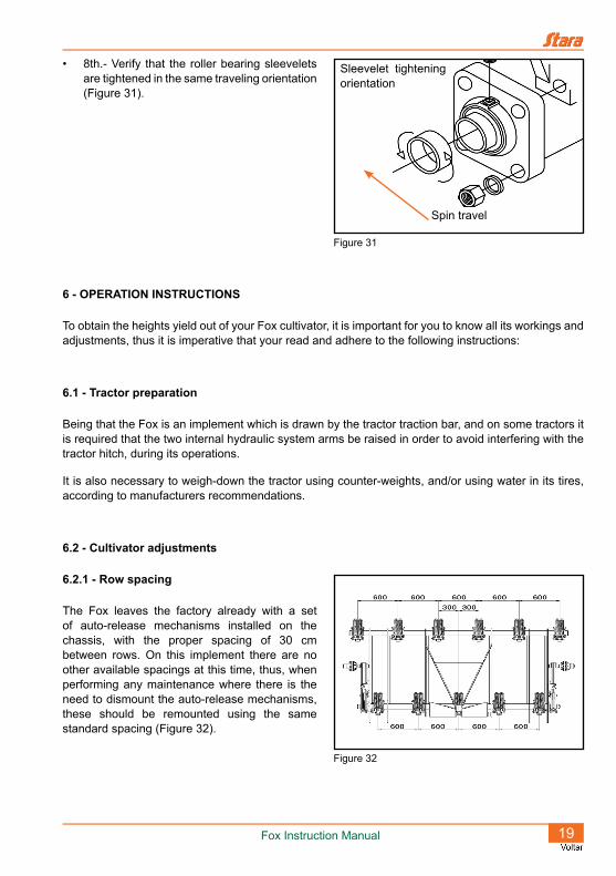
• 8th.- Verify that the roller bearing sleevelets are tightened in the same traveling orientation (Figure 31).
6 - OPERATION INSTRUCTIONS
To obtain the heights yield out of your Fox cultivator, it is important for you to know all its workings and adjustments, thus it is imperative that your read and adhere to the following instructions:
6.1 - Tractor preparation
Being that the Fox is an implement which is drawn by the tractor traction bar, and on some tractors it is required that the two internal hydraulic system arms be raised in order to avoid interfering with the tractor hitch, during its operations.
It is also necessary to weigh-down the tractor using counter-weights, and/or using water in its tires, according to manufacturers recommendations.
6.2 - Cultivator adjustments
6.2.1 - Row spacing
The Fox leaves the factory already with a set of auto-release mechanisms installed on the chassis, with the proper spacing of 30 cm between rows. On this implement there are no other available spacings at this time, thus, when performing any maintenance where there is the need to dismount the auto-release mechanisms, these should be remounted using the same standard spacing (Figure 32).
Figure 31
Spin travel
Sleevelet tightening orientation
Figure 32

20 Fox Instruction Manual
6.2.2 - Working depth
The job depth is limited by the adjustment rods (Figure 33).
CAUTION!The adjustment rods should be set to the same height on both sides of the implement, thus avoiding the twisting of the wheel axles.
6.2.3 - Leveling
So that all shanks penetrate the soil at the same depth, mount the hitch hook-up on the best hitch mounting holes, those which best match the tractor traction bar height. The chassis should remain in a horizontal position with the tiller resting on the ground (Figure 34).
6.2.4 - Shank auto-release mechanism adjust-ment
The Fox cultivator leaves the factory with the spring length set at 29 cm “B”, for normal working conditions. To increase the spring tension, tighten the “A” nuts, and to decrease the tension loosen the nuts. These adjustment are done within the limits of 27.5 cm and 30 cm for spring lengths (Figure 35).
Figure 33
ADJUSTMENT RODS
Figure 34
HITCH
MOUNTING
BOLT
HITCH HOOK-
UP
Figure 35
Min 275
Max 300ADJUSTMENT
NUT
SPRING
Fox Instruction Manual 21
NOTE!To make best use of the tiller oscillation, work with the lowest spring tension possible, as long as the tiller does not trip the auto-release while working under normal conditions.
6.2.5 - Leveling roller, operations and adjust-ments
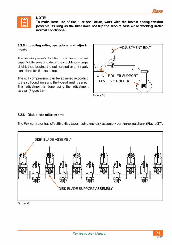
The leveling roller’s function, is to level the soil superficially, pressing down the stubble or clumps of dirt, thus leaving the soil leveled and in ready conditions for the next crop.
The soil compression can be adjusted according to the soil conditions and the type of finish desired. This adjustment is done using the adjustment screws (Figure 36).
6.2.6 - Disk blade adjustments
The Fox cultivator has offsetting disk types, being one disk assembly per furrowing shank (Figure 37).
Figure 36
ADJUSTMENT BOLT
ROLLER SUPPORT
LEVELING ROLLER
Figure 37
DISK BLADE ASSEMBLY
DISK BLADE SUPPORT ASSEMBLY
22 Fox Instruction Manual
6.2.6.1 - Spring tension adjustments
To obtain the ideal working tension, it is necessary to tighten the blade disk spring, until the spring does not oscillate during the job, but allows the disks to lift and escape obstacles, when encountered.
Spring adjustment is done by the nut located on top of the spring.
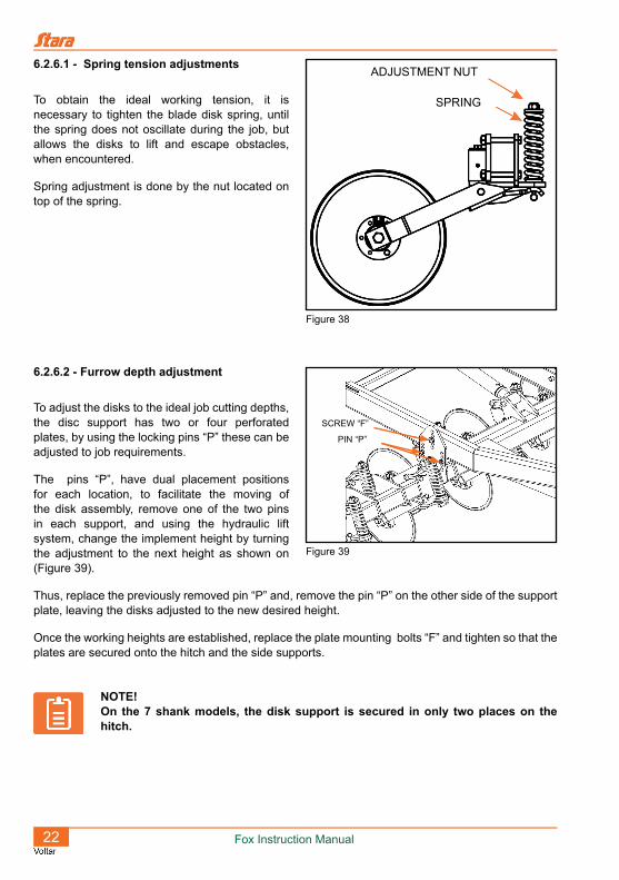
6.2.6.2 - Furrow depth adjustment
To adjust the disks to the ideal job cutting depths, the disc support has two or four perforated plates, by using the locking pins “P” these can be adjusted to job requirements.
The pins “P”, have dual placement positions for each location, to facilitate the moving of the disk assembly, remove one of the two pins in each support, and using the hydraulic lift system, change the implement height by turning the adjustment to the next height as shown on (Figure 39).
Thus, replace the previously removed pin “P” and, remove the pin “P” on the other side of the support plate, leaving the disks adjusted to the new desired height.
Once the working heights are established, replace the plate mounting bolts “F” and tighten so that the plates are secured onto the hitch and the side supports.
NOTE!On the 7 shank models, the disk support is secured in only two places on the hitch.
Figure 38
ADJUSTMENT NUT
SPRING
Figure 39
SCREW “F”
PIN “P”
Fox Instruction Manual 23
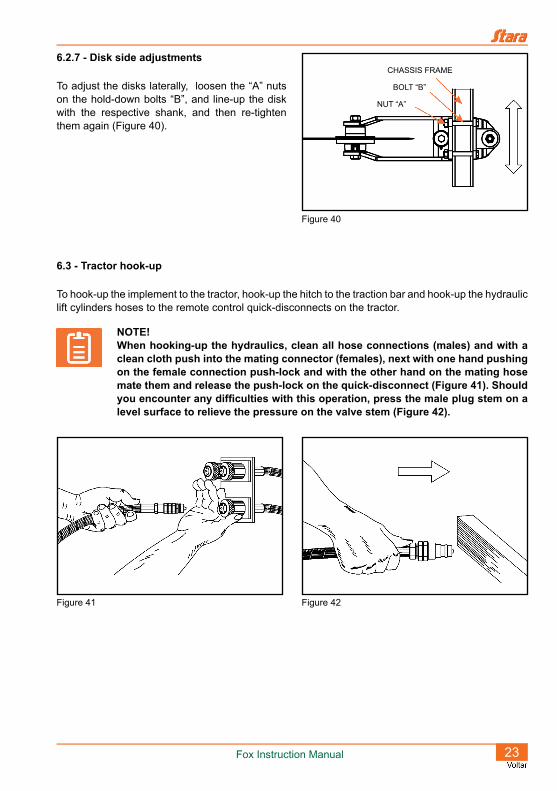
6.2.7 - Disk side adjustments
To adjust the disks laterally, loosen the “A” nuts on the hold-down bolts “B”, and line-up the disk with the respective shank, and then re-tighten them again (Figure 40).
6.3 - Tractor hook-up
To hook-up the implement to the tractor, hook-up the hitch to the traction bar and hook-up the hydraulic lift cylinders hoses to the remote control quick-disconnects on the tractor.
NOTE!When hooking-up the hydraulics, clean all hose connections (males) and with a clean cloth push into the mating connector (females), next with one hand pushing on the female connection push-lock and with the other hand on the mating hose mate them and release the push-lock on the quick-disconnect (Figure 41). Should you encounter any difficulties with this operation, press the male plug stem on a level surface to relieve the pressure on the valve stem (Figure 42).
Figure 41 Figure 42
Figure 40
CHASSIS FRAME
BOLT “B”
NUT “A”

24 Fox Instruction Manual
7 - MAINTENANCE
The Fox cultivator was designed to work in rock-free soils, and at depths up to 26 cm. Under these working conditions, the implement will have a long useful working life, if certain maintenance cares are applied, such as:
• Daily re-tighten all nuts and bolts, for these take the brunt stresses during the job.
• During the job, the cutting points will waste away and should be replaced when the implement shows signs of the soil penetration difficulties, or when there is the first signs of ware on the front side of the pointer, as shown on (Figure 43).
• Periodically grease the wheel hubs, the disk bearing fixtures, the leveling roller basket, the wheel axle, the adjustments bolts, the cylinder pivot joints and the wheel linkages.
• Use nº 2 grease on the grease fittings, as indicated on the implement’s decals (Figure 44).
• Periodically check tire pressures. Normal tire pressure is 40 PSI.
• Look for hydraulic system leaks, for additional detailed information see “Table 3” on page 28.
• Maintain all protective covers/caps on the quick-disconnects, when not in use.
Worn due to the excessive ware on the
pointer.
Figure 43
Figure 44
Fox Instruction Manual 25
Should the cultivator remain inactive for a long period of time, wash it down, touch-up the paint job, give it an oil bath to deter corrosion and store it under a covering.
8 - OPERATION
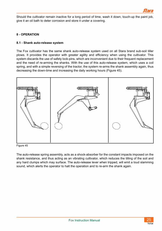
8.1 - Shank auto-release system
The Fox cultivator has the same shank auto-release system used on all Stara brand sub-soil tiller plows. It provides the operator with greater agility and efficiency when using the cultivator. This system discards the use of safety lock-pins, which are inconvenient due to their frequent replacement and the need of re-arming the shanks. With the use of this auto-release system, which uses a coil spring, and with a simple reversing of the tractor, the system re-arms the shank assembly again, thus decreasing the down-time and increasing the daily working hours (Figure 45).
The auto-release spring assembly, acts as a shock-absorber for the constant impacts imposed on the shank resistance, and thus acting as an vibrating cultivator, which reduces the tilling of the soil and any hard clumps which may surface. The auto-release lever when tripped, will emit a loud slamming sound, which alerts the operator to halt the operation and to re-arm the shank again.
Figure 45
26 Fox Instruction Manual
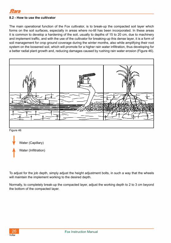
8.2 - How to use the cultivator
The main operational function of the Fox cultivator, is to break-up the compacted soil layer which forms on the soil surfaces, especially in areas where no-till has been incorporated. In these areas it is common to develop a hardening of the soil, usually to depths of 15 to 20 cm, due to machinery and implement traffic, and with the use of the cultivator for breaking-up this dense layer, it is a form of soil management for crop ground coverage during the winter months, also while amplifying their root system on the loosened soil, which will promote for a higher rain water infiltration, thus developing for a better radial plant growth and, reducing damages caused by rushing rain water erosion (Figure 46).
Water (Capillary)
Water (Infiltration)
To adjust for the job depth, simply adjust the height adjustment bolts, in such a way that the wheels will maintain the implement working to the desired depth.
Normally, to completely break-up the compacted layer, adjust the working depth to 2 to 3 cm beyond the bottom of the compacted layer.
Figure 46
Fox Instruction Manual 27
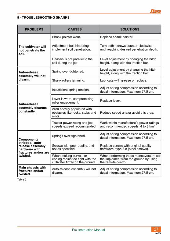
9 - TROUBLESHOOTING SHANKS
Table 2
PROBLEMS CAUSES SOLUTIONS
The cultivator will not penetrate the soil.
Shank pointer worn. Replace shank pointer.
Adjustment bolt hindering implement soil penetration.
Turn both screws counter-clockwise until reaching desired penetration depth.
Chassis is not parallel to the soil during the job.
Level adjustment by changing the hitch height, along with the traction bar.
Auto-release assembly will not disarm.
Spring over-tightened. Level adjustment by changing the hitch height, along with the traction bar.
Shank rollers jamming. Lubricate with grease or replace.
Auto-release assembly disarms constantly.
Insufficient spring tension. Adjust spring compression according to decal information. Maximum 27.5 cm.
Lever is worn, compromising roller engagement. Replace lever.
Area heavily populated with obstacles like rocks, stubs and roots.
Reduce speed and/or avoid this area.
Tractor power rating and job speeds exceed recommended.
Work within manufacture´s power ratings and recommended speeds: 4 to 8 km/h.
Components stripped, auto-release assembly hardware with fractures and/or are twisted.
Springs over-tightened. Adjust spring compression according to decal information. Maximum 27.5 cm.
Screws with poor quality, and not as specified.
Replace screws with original quality hardware, type 8.8 (steel screws).
When making curves, or ending radius too tight with the cultivator firmly on the ground.
When performing these maneuvers, raise the implement from the ground by using the remote control.
Main chassis with fractures and/or twisted.
Auto-release assembly will not disarm.
Adjust spring compression according to decal information. Maximum 27.5 cm.

28 Fox Instruction Manual
10 - TROUBLESHOOTING HYDRAULICS
To check for damages, fully expose the shanks and examine its surfaces, checking for gouges or burrs.
Table 3
PROBLEMS CAUSES SOLUTIONS
Quick-disconnects will not hook-up. Quick-disconnects mismatched. Change out for mating matched sets.
Equipment will not move in any direction, or moves with great difficulty.
Unequal plug pressure. Adjust or replace as needed.
Low controller hydraulic pressure. Adjust the controller through the relief valve using a manometer.
Hoses swapped. Fully inspect and remount hoses correctly.
Defective hydraulic cylinders. Replace repairs or replace cylinders.
Tractor with an inadequate hydraulic system.
Confirm by changing out the tractor for another, or repair tractor.
Low oil level. Complete to fill-line.
Hose leaks on fixed connections.
Inadequate tightening. Carefully retighten.
Lack of thread sealant. Use sealing tape and re-tighten carefully.
Hose leaks on quick-disconnects.
Inadequate tightening. Re-tighten carefully.
Lack of thread sealant. Use sealing tape and re-tighten carefully.
Damaged repairs. Replace damaged repairs.
The implement moves without operating the controller.
Hydraulic cylinder with damaged repairs.
Identify damaged cylinder and replace it.
Warranty Claims
Technical Delivery
a) Stara, claims the right of a Technical Delivery to the first owner/purchaser of the implement, touching on the following items like: assembly, adjustments, operations, maintenance and warranty.
b) The owner of the machine should designate one or more operators to be trained.
c) It shall be up to the owner, that all instructions listed in the operation and maintenance manual be adhered to and be rigorously followed.
d) Maintain the implement and all respective manuals in a perfect state of conservation, and on a regular maintenance schedule, thus preserving the right to warranty claims.
Warranty Terms
a) The warranty here expressed is the responsibility of the implement dealership along with the client. Thus, it is understood, that there is no direct dealings between the said client and the factory.
b) It is here defined that the first purchaser of the implement is the DEALERSHIP, and the second purchaser will be here established as the CLIENT.
c) The following conditions are basic and will be that, the dealership will submit to Stara’s judgment all warranty claims.
Warranty Conditions
a) Stara guarantees its product “only to” the DEALERSHIP, and for the period of six months, being this period of three (03) months under legal warranty, and an additional three (03) months of STARA contractual warranty, starting on the day of delivery to the CLIENT, along with the original invoice and warranty certificate, which must be presented at the time of claim.
b) Stara restricts its responsibility strictly to the terms herewith contained in this warranty, which will become non-transferable an will terminate automatically, in case of the resale of the implement by the second owner, the CLIENT or warranty termination by the CLIENT.
c) The warranty covers exclusively material defects and/or of fabrication defects, being that, labor, freight, and other expenditures are not covered by the Warranty, for they are the responsibility of the DEALERSHIP.
d) Requested revisions by the CLIENT, even though the implement is still under warranty, will be subject to charges.
e) The warranty of parts and components which were replaced, will end with the warranty of the implement.
f) In cases of warranty service delays, those will not warrant the purchaser the right to indemnity for damages, or extension of the warranty.

Items Excluded from the Warranty
Not included are such items as: hydraulic oils and lubricants, filters, greases and the like,charges for roadside assistance or help, on-site assistance and any implement maintenance or help by Stara personnel; all these are the responsibility of the purchaser.
Also not inclusive are: tires, inner tubes, electrical and electronic implement, batteries, engine, starter motor, alternator, fuel injection pump, these again are not inclusive of Stara’s warranty since they have specific manufacturer’s warranty on each of said components.
Other charges or expenses such as: transportation or travel expenses, towing services, material damages or damages against the owner or his agents , these are the sole responsibilities of the purchaser, until otherwise proven through the results of investigations done by qualified and certified agents of the state or government.
Stara S/A, The Agricultural Machinery and Implements Company Não-Me-Toque - RS - Brazil
Warranty Forfeiture
The warranty will become null and void at such time as:
a) It is established that the defects or damages are the result of, inappropriate use of the implement, through the failure of not following instructions as specified on the supplied manual, or the failure of untrained or inexperienced operators.
b) The product suffered repairs or modifications in repair shops which are not part of Stara’s authorized dealerships.
c) The parts or components present damages due to inappropriate use, or damaged by other parts which are not genuine or original parts of the implement, by the end user.
d) The product suffers any type of misuse, even to the extent of causing safety issues,concerns or breaches, and it will be per the company’s judgment on such matters, and it will carry the final word,
e) The implement is not up to date on all current revisions or upgrades, and/or if the owner will not furnish solicited documentation.
f) The hydraulic system is contaminated by impurities of unauthorized or non-recommended fluids.
g) The implement is found to have damaged, scraped, illegible or no identification plate.
h) the warranty is found to have incomplete or erroneous information or any unauthorized alterations.
i) The implement was adversely misused in situations such as: working or was driven at speeds which exceeded recommended speeds, cross wide terraces, overloading implement during work, etc.
j) Any fabrication defects and/or material defects, the object of this warranty, will not constitute, under no hypothesis, will it be a motive to rescind any purchase or sales contracts/agreements, nor will it warrant the purchaser the right to indemnity of any nature.
TECHNICAL ASSISTANCE
Besides the instruction manual, the users of Stara products can call the nearest authorized dealership to obtain any needed assistance. The dealership, by its own merit, can seek information and assistance from the after-sales department at Stara, whenever a difficult situation presents itself, or the need arises to resolve any problems.
PROJECT MODIFICATIONS
STARA S/A reserves the right to introduce project modifications to its products and/or upgrades, without any obligations to apply these to products previously manufactured.
REPLACEMENT PARTS
Parts replacement should only be done using original parts from Stara, the which , besides preserving the warranty rights as a consumer, will not compromise the operation and the maintenance of the implement.
Stara S/A, The Agricultural Machinery and Implements Company Não-Me-Toque - RS - Brazil


IMPORTANT!
Warranty issues will only be address if this certificate is properly filled-out at the time of delivery by the technician. This certificate must be presented with every warranty claim,
along with the sales invoice.
DATE OF SALE: / /
INVOICE NUMBER:
NAME:
STAMP AND SIGNATURE:
NAME: PHONE:
ADDRESS:
MODEL:
MANUFACTURED DATE:
SERIAL NUMBER:
WARRANTY CERTIFICATE
CLIENT INFORMATION
DEALER OR SALESMAN INFORMATION
PURCHASED PRODUCT INFORMATION


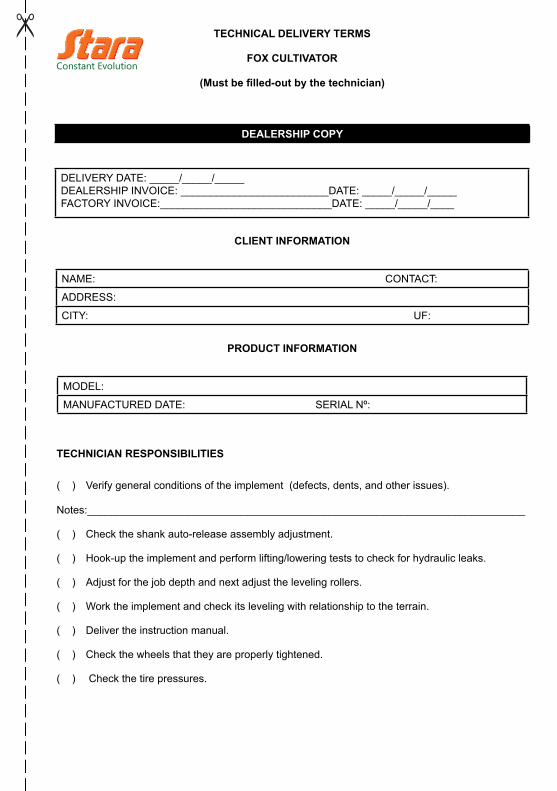
TECHNICAL DELIVERY TERMS
FOX CULTIVATOR
(Must be filled-out by the technician)
CUSTOMER COPY
DELIVERY DATE: _____/_____/_____DEALERSHIP INVOICE: _________________________DATE: _____/_____/_____FACTORY INVOICE:_____________________________DATE: _____/_____/____
CLIENT INFORMATION
NAME: CONTACT:
ADDRESS:
CITY: UF:
PRODUCT INFORMATION
MODEL:
MANUFACTURED DATE: SERIAL Nº:
TECHNICIAN RESPONSIBILITIES
( ) � Verify general conditions of the implement (defects, dents, and other issues).
Notes:__________________________________________________________________________
( ) � Check the shank auto-release assembly adjustment.
( ) � Hook-up the implement and perform lifting/lowering tests to check for hydraulic leaks.
( ) � Adjust for the job depth and next adjust the leveling rollers.
( ) � Work the implement and check its leveling with relationship to the terrain.
( ) � Deliver the instruction manual.
( ) � Check the wheels that they are properly tightened.
( ) � Check the tire pressures.
OPERATOR INSTRUCTIONS REGARDING:
( ) � Adjust all depth limiters, maintaining both sides to the same settings.
( ) � Adjust leveling rollers whenever the job depth is modified.
( ) � Always maintain the implement leveled, or with a slight tilt towards the front, when working a job.
( ) � When needed, replace the shank point, so that the shank will not be damaged.
( ) � Respecting maximum job depth settings.
( ) � How to rearm the shank when tripped.
( ) � Periodic maintenance of the implement, in the day-to-day and after each harvest.
( ) � The instruction manual, warranty certificate and warranty claims.
SEEDING KIT
Verify general conditions of the implement (defects, dents, and other issues).
Note:___________________________________________________________________________
( ) � Check the transmission chain operation;
( ) � Verify that the rotor opening adjustment needle is at the “O” mark when it is totally.

ADDITIONAL INFORMATION
____________________________________________________________________________________________________________________________________________________________________________________________________________________________________________________________________________________________________________________________
We declare that the implement referenced in this document, is being delivered under normal conditions of use, as described and, with the various adjustments and instructions.
_______________________________________________, _____/_____/_____
Location Date
__________________________________
CLIENT SIGNATURE
_________________________________
TECHNICIAN OR REPRESENTATIVE SIGNATURE

TECHNICAL DELIVERY TERMS
FOX CULTIVATOR
(Must be filled-out by the technician)
DEALERSHIP COPY
DELIVERY DATE: _____/_____/_____DEALERSHIP INVOICE: _________________________DATE: _____/_____/_____FACTORY INVOICE:_____________________________DATE: _____/_____/____
CLIENT INFORMATION
NAME: CONTACT:
ADDRESS:
CITY: UF:
PRODUCT INFORMATION
MODEL:
MANUFACTURED DATE: SERIAL Nº:
TECHNICIAN RESPONSIBILITIES
( ) � Verify general conditions of the implement (defects, dents, and other issues).
Notes:__________________________________________________________________________
( ) � Check the shank auto-release assembly adjustment.
( ) � Hook-up the implement and perform lifting/lowering tests to check for hydraulic leaks.
( ) � Adjust for the job depth and next adjust the leveling rollers.
( ) � Work the implement and check its leveling with relationship to the terrain.
( ) � Deliver the instruction manual.
( ) � Check the wheels that they are properly tightened.
( ) � Check the tire pressures.

OPERATOR INSTRUCTIONS REGARDING:
( ) � Adjust all depth limiters, maintaining both sides to the same settings.
( ) � Adjust leveling rollers whenever the job depth is modified.
( ) � Always maintain the implement leveled, or with a slight tilt towards the front, when working a job.
( ) � When needed, replace the shank point, so that the shank will not be damaged.
( ) � Respecting maximum job depth settings.
( ) � How to rearm the shank when tripped.
( ) � Periodic maintenance of the implement, in the day-to- day and after each harvest.
( ) � The instruction manual, warranty certificate and warranty claims.
SEEDING KIT
Verify general conditions of the implement (defects, dents, and other issues).
Note:___________________________________________________________________________
( ) � Check the transmission chain operation;
( ) � Verify that the rotor opening adjustment needle is at the “O” mark when it is totally.

ADDITIONAL INFORMATION
____________________________________________________________________________________________________________________________________________________________________________________________________________________________________________________________________________________________________________________________
We declare that the implement referenced in this document, is being delivered under normal conditions of use, as described and, with the various adjustments and instructions.
_______________________________________________, _____/_____/_____
Location Date
__________________________________
CLIENT SIGNATURE
_________________________________
TECHNICIAN OR REPRESENTATIVE SIGNATURE

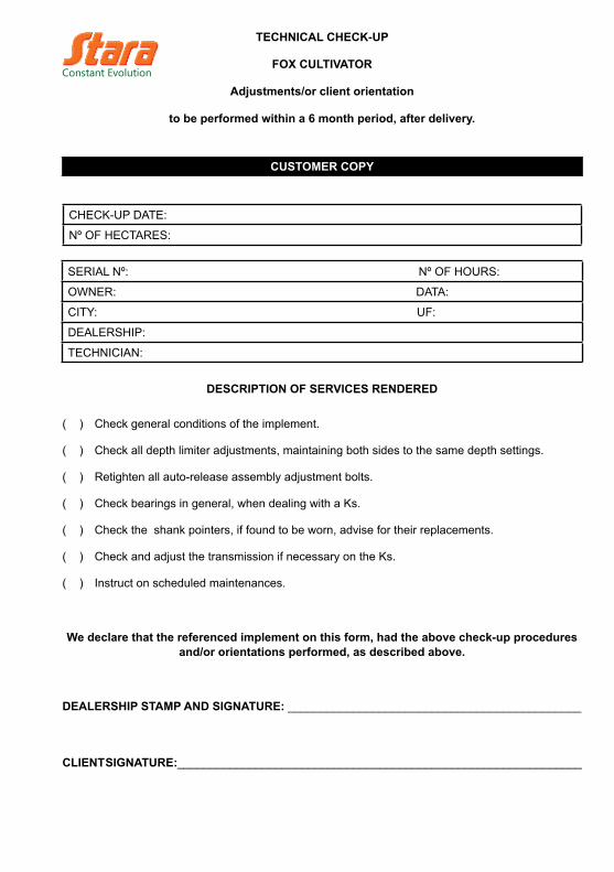
TECHNICAL CHECK-UP
FOX CULTIVATOR
Adjustments/or client orientation
to be performed within a 6 month period, after delivery.
CUSTOMER COPY
CHECK-UP DATE:
Nº OF HECTARES:
SERIAL Nº: Nº OF HOURS:
OWNER: DATA:
CITY: UF:
DEALERSHIP:
TECHNICIAN:
DESCRIPTION OF SERVICES RENDERED
( ) � Check general conditions of the implement.
( ) � Check all depth limiter adjustments, maintaining both sides to the same depth settings.
( ) � Retighten all auto-release assembly adjustment bolts.
( ) � Check bearings in general, when dealing with a Ks.
( ) � Check the shank pointers, if found to be worn, advise for their replacements.
( ) � Check and adjust the transmission if necessary on the Ks.
( ) � Instruct on scheduled maintenances.
We declare that the referenced implement on this form, had the above check-up procedures and/or orientations performed, as described above.
DEALERSHIP STAMP AND SIGNATURE: _____________________________________________
CLIENT SIGNATURE:______________________________________________________________


TECHNICAL CHECK-UP
FOX CULTIVATOR
Adjustments/or client orientation
to be performed within a 6 month period, after delivery.
DEALERSHIP COPY
CHECK-UP DATE:
Nº OF HECTARES:
SERIAL Nº: Nº OF HOURS:
OWNER: DATA:
CITY : UF:
DEALERSHIP:
TECHNICIAN:
DESCRIPTION OF SERVICES RENDERED
( ) � Check general conditions of the implement.
( ) � Check all depth limiter adjustments, maintaining both sides to the same depth settings.
( ) � Retighten all auto-release assembly adjustment bolts.
( ) � Check bearings in general, when dealing with a Ks.
( ) � Check the shank pointers, if found to be worn, advise for their replacements.
( ) � Check and adjust the transmission if necessary on the Ks.
( ) � Instruct on scheduled maintenances.
We declare that the referenced implement on this form, had the above check-up procedures and/or orientations performed, as described above.
DEALERSHIP STAMP AND SIGNATURE: _____________________________________________
CLIENT SIGNATURE:______________________________________________________________


Stara S/A - © 2014All rights reserved.
No part of this publication can be reproduced, stored in a data bank or transmitted in any form without express written permission from Stara.
The images in this manual are merely illustrations. Stara reserves the right to make changes at anytime without any prior consent or
notifications.

STARA S/A - The Agricultural Machinery and Implements Co. Av. Stara, 519 - Caixa Postal 53 - Não-Me-Toque/RS - BrasilPhone/Fax: +55 54 3332-2800 - CEP: 99470-000e-mail: [email protected]