Embed Size (px)
Citation preview
C
A new d
CUBInstr
design t
Serving
E HOruction
ModeVers
o solve
the coin-m
OPP
n - Serv
el 10-170
ion 4.0 / Apr
most of
machine ind
ER®
vice Ma00-XX
2008
f your pa
dustries sin
MKIanual
ayout pro
nce 1955
Ap
II
oblems!
pproved
!
Cube Hopper MKII Page 2
© Suzo International (NL) Rev 4.0 Apr 2008
TABLE OF CONTENTS
REFERENCE CHART ............................................................................................ 3 INSTRUCTION MANUAL ....................................................................................... 4
Standard hopper for different applications ............................................. 4 Features ...................................................................................................... 4 Disassembly ............................................................................................... 4
How to remove the disc ............................................................................................ 4 How to remove the coin insert plate ......................................................................... 4 How to re-configure the Cube Hopper ...................................................................... 4
SERVICE MANUAL ............................................................................................... 5
1. Electrical features ................................................................................. 5 1.1 Connections ....................................................................................................... 5 1.2 Motor control ...................................................................................................... 5 1.3 Current consumption .......................................................................................... 5 1.4 Power supply requirements ................................................................................ 5 1.5 Coin counting ..................................................................................................... 5 1.6 Continuous monitored optic control ................................................................... 5
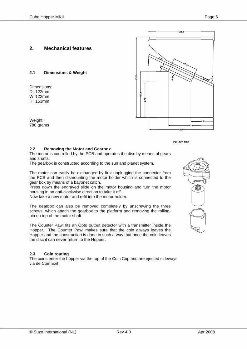
2. Mechanical features ............................................................................. 6
2.1 Dimensions & weight .......................................................................................... 6 2.2 Removing the Motor and Gearbox ..................................................................... 6 2.3 Coin routing ........................................................................................................ 6
3. Maintenance .......................................................................................... 7 3.1 Removing and re-installing the hopper .............................................................. 7 3.2 Cleaning materials ............................................................................................. 7 3.3 Test equipment .................................................................................................. 7
4. Troubleshooting ................................................................................... 8 4.1 Motor fails to run ................................................................................................ 8 4.2 Over payout of coins .......................................................................................... 8 4.3 Under payout of coins ........................................................................................ 8 4.4 No payout signal ................................................................................................ 8
5. Optional add-ons .................................................................................. 9 5.1 Cup extension .................................................................................................... 9 5.2 Driver interface cable ......................................................................................... 9
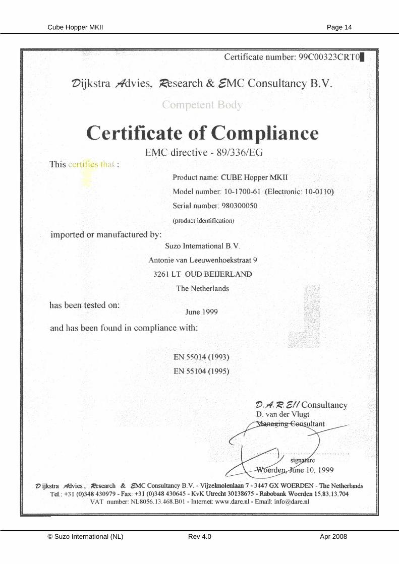
SCHEMATIC DIAGRAM ...................................................................................... 11 EXPLODED VIEW ................................................................................................ 13 CERTIFICATE OF EC COMPLIANCE ................................................................. 14 TECHNICAL SPECS ............................................................................................ 15
Cube Hopper MKII Page 3
© Suzo International (NL) Rev 4.0 Apr 2008
REFERENCE CHART
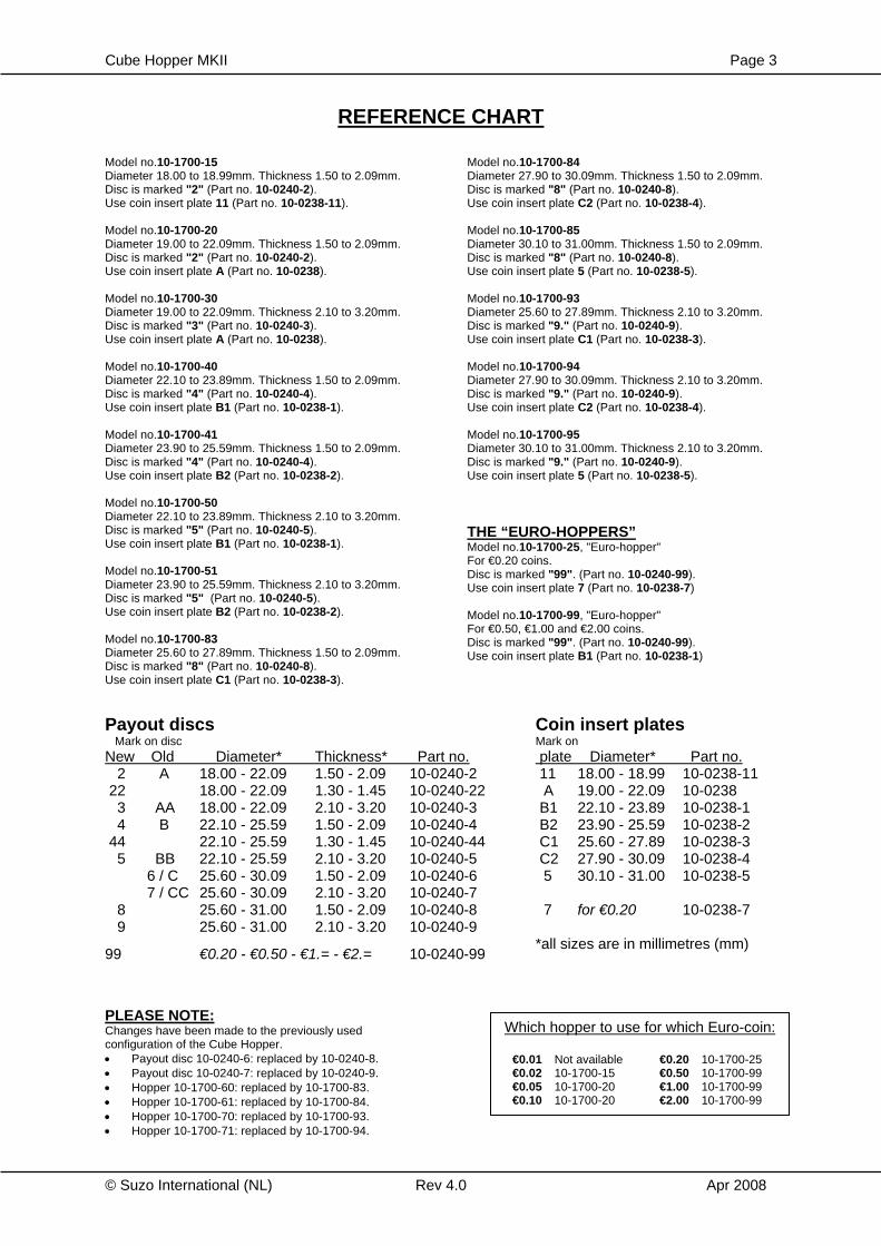
Model no.10-1700-15 Diameter 18.00 to 18.99mm. Thickness 1.50 to 2.09mm. Disc is marked "2" (Part no. 10-0240-2). Use coin insert plate 11 (Part no. 10-0238-11). Model no.10-1700-20 Diameter 19.00 to 22.09mm. Thickness 1.50 to 2.09mm. Disc is marked "2" (Part no. 10-0240-2). Use coin insert plate A (Part no. 10-0238). Model no.10-1700-30 Diameter 19.00 to 22.09mm. Thickness 2.10 to 3.20mm. Disc is marked "3" (Part no. 10-0240-3). Use coin insert plate A (Part no. 10-0238). Model no.10-1700-40 Diameter 22.10 to 23.89mm. Thickness 1.50 to 2.09mm. Disc is marked "4" (Part no. 10-0240-4). Use coin insert plate B1 (Part no. 10-0238-1). Model no.10-1700-41 Diameter 23.90 to 25.59mm. Thickness 1.50 to 2.09mm. Disc is marked "4" (Part no. 10-0240-4). Use coin insert plate B2 (Part no. 10-0238-2). Model no.10-1700-50 Diameter 22.10 to 23.89mm. Thickness 2.10 to 3.20mm. Disc is marked "5" (Part no. 10-0240-5). Use coin insert plate B1 (Part no. 10-0238-1). Model no.10-1700-51 Diameter 23.90 to 25.59mm. Thickness 2.10 to 3.20mm. Disc is marked "5" (Part no. 10-0240-5). Use coin insert plate B2 (Part no. 10-0238-2). Model no.10-1700-83 Diameter 25.60 to 27.89mm. Thickness 1.50 to 2.09mm. Disc is marked "8" (Part no. 10-0240-8). Use coin insert plate C1 (Part no. 10-0238-3).
Model no.10-1700-84 Diameter 27.90 to 30.09mm. Thickness 1.50 to 2.09mm. Disc is marked "8" (Part no. 10-0240-8). Use coin insert plate C2 (Part no. 10-0238-4). Model no.10-1700-85 Diameter 30.10 to 31.00mm. Thickness 1.50 to 2.09mm. Disc is marked "8" (Part no. 10-0240-8). Use coin insert plate 5 (Part no. 10-0238-5). Model no.10-1700-93 Diameter 25.60 to 27.89mm. Thickness 2.10 to 3.20mm. Disc is marked "9." (Part no. 10-0240-9). Use coin insert plate C1 (Part no. 10-0238-3). Model no.10-1700-94 Diameter 27.90 to 30.09mm. Thickness 2.10 to 3.20mm. Disc is marked "9." (Part no. 10-0240-9). Use coin insert plate C2 (Part no. 10-0238-4). Model no.10-1700-95 Diameter 30.10 to 31.00mm. Thickness 2.10 to 3.20mm. Disc is marked "9." (Part no. 10-0240-9). Use coin insert plate 5 (Part no. 10-0238-5). THE “EURO-HOPPERS” Model no.10-1700-25, "Euro-hopper" For €0.20 coins. Disc is marked "99". (Part no. 10-0240-99). Use coin insert plate 7 (Part no. 10-0238-7) Model no.10-1700-99, "Euro-hopper" For €0.50, €1.00 and €2.00 coins. Disc is marked "99". (Part no. 10-0240-99). Use coin insert plate B1 (Part no. 10-0238-1)
Payout discs Mark on disc New Old Diameter* Thickness* Part no. 2 A 18.00 - 22.09 1.50 - 2.09 10-0240-2 22 18.00 - 22.09 1.30 - 1.45 10-0240-22 3 AA 18.00 - 22.09 2.10 - 3.20 10-0240-3 4 B 22.10 - 25.59 1.50 - 2.09 10-0240-4 44 22.10 - 25.59 1.30 - 1.45 10-0240-44 5 BB 22.10 - 25.59 2.10 - 3.20 10-0240-5 6 / C 25.60 - 30.09 1.50 - 2.09 10-0240-6 7 / CC 25.60 - 30.09 2.10 - 3.20 10-0240-7 8 25.60 - 31.00 1.50 - 2.09 10-0240-8 9 25.60 - 31.00 2.10 - 3.20 10-0240-9
99 €0.20 - €0.50 - €1.= - €2.= 10-0240-99
Coin insert plates Mark on plate Diameter* Part no. 11 18.00 - 18.99 10-0238-11 A 19.00 - 22.09 10-0238 B1 22.10 - 23.89 10-0238-1 B2 23.90 - 25.59 10-0238-2 C1 25.60 - 27.89 10-0238-3 C2 27.90 - 30.09 10-0238-4 5 30.10 - 31.00 10-0238-5 7 for €0.20 10-0238-7 *all sizes are in millimetres (mm)
PLEASE NOTE: Changes have been made to the previously used configuration of the Cube Hopper. • Payout disc 10-0240-6: replaced by 10-0240-8. • Payout disc 10-0240-7: replaced by 10-0240-9. • Hopper 10-1700-60: replaced by 10-1700-83. • Hopper 10-1700-61: replaced by 10-1700-84. • Hopper 10-1700-70: replaced by 10-1700-93. • Hopper 10-1700-71: replaced by 10-1700-94.
Which hopper to use for which Euro-coin:
€0.01 Not available €0.20 10-1700-25 €0.02 10-1700-15 €0.50 10-1700-99 €0.05 10-1700-20 €1.00 10-1700-99 €0.10 10-1700-20 €2.00 10-1700-99
Cube Hopper MKII Page 4
© Suzo International (NL) Rev 4.0 Apr 2008
Congratulations on your purchase of this CUBE HOPPER MKII and thank you for having confidence in our STC quality products
Instruction Manual
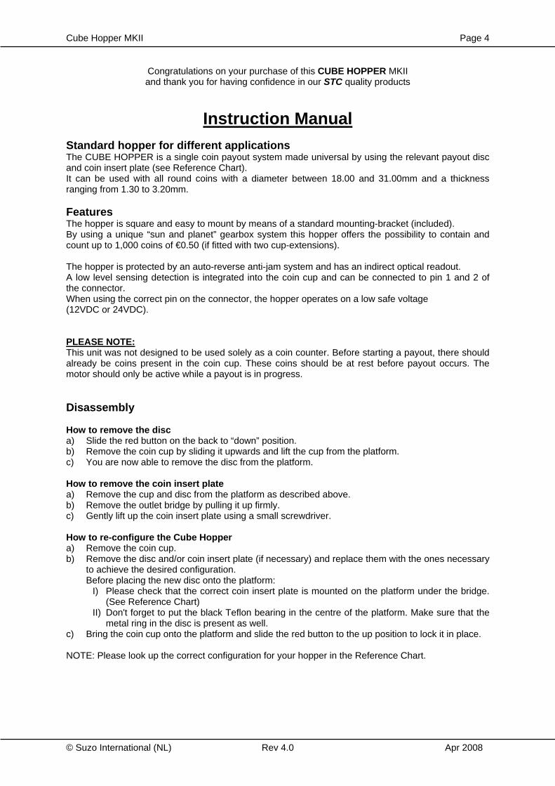
Standard hopper for different applications The CUBE HOPPER is a single coin payout system made universal by using the relevant payout disc and coin insert plate (see Reference Chart). It can be used with all round coins with a diameter between 18.00 and 31.00mm and a thickness ranging from 1.30 to 3.20mm. Features The hopper is square and easy to mount by means of a standard mounting-bracket (included). By using a unique “sun and planet” gearbox system this hopper offers the possibility to contain and count up to 1,000 coins of €0.50 (if fitted with two cup-extensions). The hopper is protected by an auto-reverse anti-jam system and has an indirect optical readout. A low level sensing detection is integrated into the coin cup and can be connected to pin 1 and 2 of the connector. When using the correct pin on the connector, the hopper operates on a low safe voltage (12VDC or 24VDC). PLEASE NOTE: This unit was not designed to be used solely as a coin counter. Before starting a payout, there should already be coins present in the coin cup. These coins should be at rest before payout occurs. The motor should only be active while a payout is in progress. Disassembly How to remove the disc a) Slide the red button on the back to “down” position. b) Remove the coin cup by sliding it upwards and lift the cup from the platform. c) You are now able to remove the disc from the platform. How to remove the coin insert plate a) Remove the cup and disc from the platform as described above. b) Remove the outlet bridge by pulling it up firmly. c) Gently lift up the coin insert plate using a small screwdriver. How to re-configure the Cube Hopper a) Remove the coin cup. b) Remove the disc and/or coin insert plate (if necessary) and replace them with the ones necessary
to achieve the desired configuration. Before placing the new disc onto the platform:
I) Please check that the correct coin insert plate is mounted on the platform under the bridge. (See Reference Chart)
II) Don't forget to put the black Teflon bearing in the centre of the platform. Make sure that the metal ring in the disc is present as well.
c) Bring the coin cup onto the platform and slide the red button to the up position to lock it in place. NOTE: Please look up the correct configuration for your hopper in the Reference Chart.
Cube Hopper MKII Page 5
© Suzo International (NL) Rev 4.0 Apr 2008
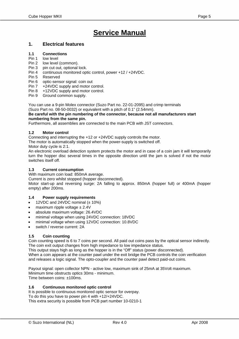
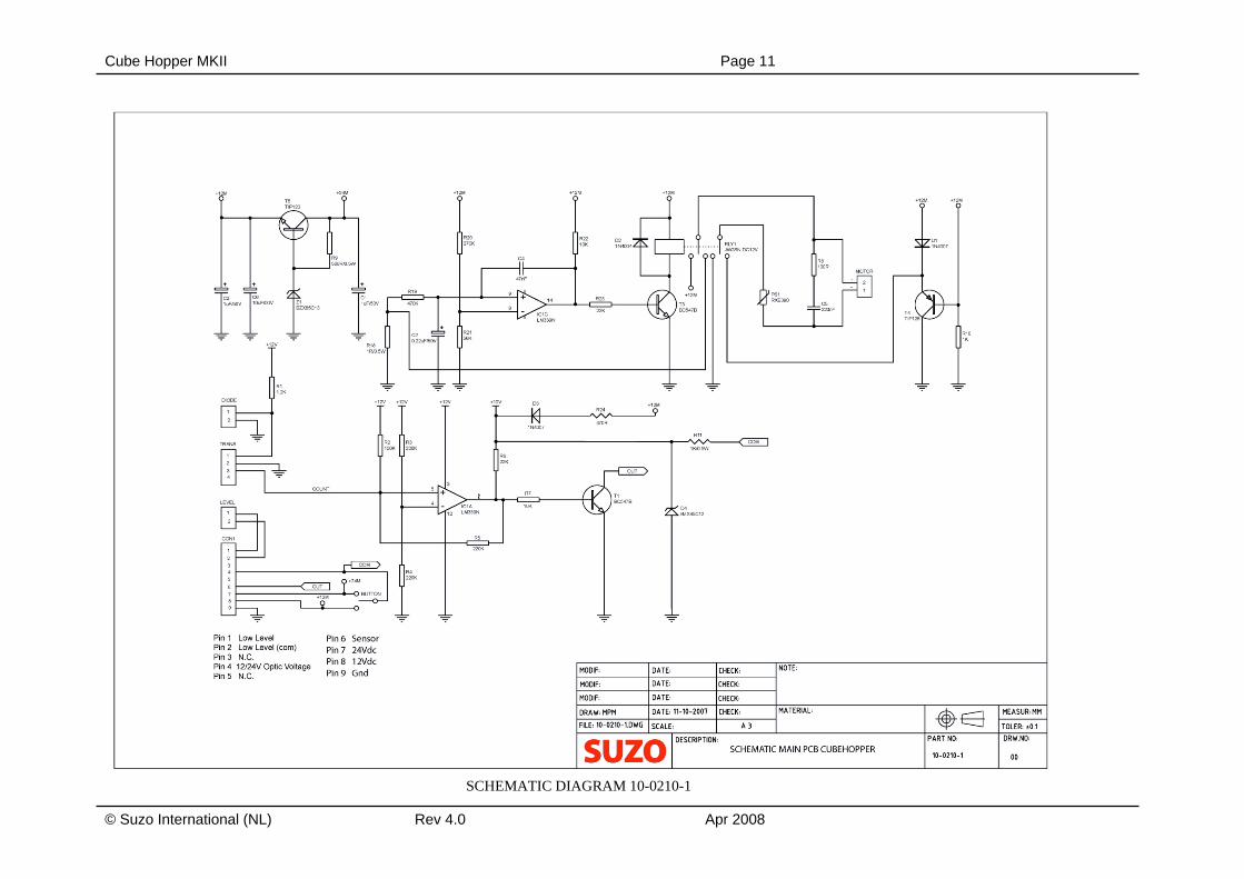
Service Manual 1. Electrical features 1.1 Connections Pin 1 low level Pin 2 low level (common). Pin 3 pin cut out, optional lock. Pin 4 continuous monitored optic control, power +12 / +24VDC. Pin 5 Reserved Pin 6 optic-sensor signal: coin out Pin 7 +24VDC supply and motor control. Pin 8 +12VDC supply and motor control. Pin 9 Ground common supply. You can use a 9-pin Molex connector (Suzo Part no. 22-01-2095) and crimp terminals (Suzo Part no. 08-50-0032) or equivalent with a pitch of 0.1” (2.54mm). Be careful with the pin numbering of the connector, because not all manufacturers start numbering from the same pin. Furthermore, all assemblies are connected to the main PCB with JST connectors. 1.2 Motor control Connecting and interrupting the +12 or +24VDC supply controls the motor. The motor is automatically stopped when the power-supply is switched off. Motor duty cycle is 2:1. An electronic overload detection system protects the motor and in case of a coin jam it will temporarily turn the hopper disc several times in the opposite direction until the jam is solved if not the motor switches itself off. 1.3 Current consumption With maximum coin load: 850mA average. Current is zero whilst stopped (hopper disconnected). Motor start-up and reversing surge: 2A falling to approx. 850mA (hopper full) or 400mA (hopper empty) after 200ms. 1.4 Power supply requirements • 12VDC and 24VDC nominal (± 10%) • maximum ripple voltage ± 2.4V • absolute maximum voltage: 26.4VDC • minimal voltage when using 24VDC connection: 18VDC • minimal voltage when using 12VDC connection: 10.8VDC • switch / reverse current: 2A 1.5 Coin counting Coin counting speed is 6 to 7 coins per second. All paid out coins pass by the optical sensor indirectly. The coin exit output changes from high impedance to low impedance status. This output stays high as long as the hopper is in the “Off” status (power disconnected). When a coin appears at the counter pawl under the exit bridge the PCB controls the coin verification and releases a logic signal. The opto-coupler and the counter pawl detect paid-out coins. Payout signal: open collector NPN - active low, maximum sink of 25mA at 35Volt maximum. Minimum time obstructs optics 30ms - minimum. Time between coins: ±100ms. 1.6 Continuous monitored optic control It is possible to continuous monitored optic sensor for overpay. To do this you have to power pin 4 with +12/+24VDC. This extra security is possible from PCB part number 10-0210-1
Cube Ho
© Suzo
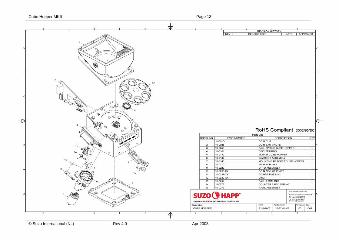
2. M 2.1 D DimensioD: 122mW: 122mH: 153m Weight: 780 gram 2.2 RThe motand shafThe gea The motthe PCBgear boxPress dohousing Now take The geascrews, pin on to The CouHopper. Hopper athe disc 2.3 CThe coinvia de C
opper MKII
International
Mechanic
Dimensions
ons: mm mm mm
ms
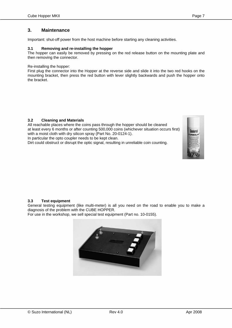
Removing ttor is controllfts. rbox is const
tor can easilB and then dx by means oown the engin an anti-cloe a new mot
arbox can awhich attach
op of the mot
unter Pawl fi The Coun
and the consit can never
Coin routingns enter the hoin Exit.
(NL)
al features
s & Weight
he Motor aned by the PC
tructed acco
y be exchandismounting of a bayonet graved slideockwise diretor and refit in
also be remh the gearbotor shaft.
ts an Opto onter Pawl mastruction is dreturn to the
g hopper via th
s
nd GearboxCB and oper
ording to the s
nged by firstthe motor hocatch. on the motction to takento the moto
oved complox to the pla
output detecakes sure th
done in such e Hopper.
he top of the
Rev 4.0
rates the disc
sun and plan
t unplugging older which
tor housing it off.
or holder.
letely by unatform and re
ctor with a trhat the coina way that o
Coin Cup an
c by means o
net system.
the connectis connected
and turn the
nscrewing themoving the
ansmitter ins always lea
once the coin
nd are ejecte
of gears
tor from d to the
e motor
e three e rolling-
side the ves the
n leaves
ed sideways
A
Page 6
pr 2008
Cube Hopper MKII Page 7
© Suzo International (NL) Rev 4.0 Apr 2008
3. Maintenance Important: shut-off power from the host machine before starting any cleaning activities. 3.1 Removing and re-installing the hopper The hopper can easily be removed by pressing on the red release button on the mounting plate and then removing the connector. Re-installing the hopper: First plug the connector into the Hopper at the reverse side and slide it into the two red hooks on the mounting bracket, then press the red button with lever slightly backwards and push the hopper onto the bracket. 3.2 Cleaning and Materials All reachable places where the coins pass through the hopper should be cleaned at least every 6 months or after counting 500,000 coins (whichever situation occurs first) with a moist cloth with dry silicon spray (Part No. 20-0124-1). In particular the opto coupler needs to be kept clean. Dirt could obstruct or disrupt the optic signal, resulting in unreliable coin counting. 3.3 Test equipment General testing equipment (like multi-meter) is all you need on the road to enable you to make a diagnosis of the problem with the CUBE HOPPER. For use in the workshop, we sell special test equipment (Part no. 10-0155).
Cube Hopper MKII Page 8
© Suzo International (NL) Rev 4.0 Apr 2008
4. Troubleshooting 4.1 Coins fail to unjam a. Are you using the correct coin insert plate? (see Reference Chart) b. Are you using the right disc? (see Reference Chart) c. Be sure Opto Coupler is clear! d. Are there bad or incorrect coins in the hopper? 4.2 Motor fails to run. a. Check the hopper fuse of the host machine. b. Protection device tripped - wait for 30 seconds with the power switched off. 4.3 Over payout of coins. a. Check the opto coupler for accumulated dirt or dust. b. Check exit monitoring by the host machine. c. Check if the hopper's power is not disconnected too slowly. Power should be disconnected directly
after the registration of the ejection of the last coin of the payout. d. Are you using the correct coin insert plate? (see Reference Chart) 4.4 Under payout of coins. a. Make sure the hopper has sufficient coins. b. Incorrect registration by the host machine. c. Incorrect exit output, debouncing by the host machine. d. Bad contact with the hopper. 4.5 No payout signal a. Please check coin insert plate.(for reference, see page 2).
Cube Hopper MKII Page 9
© Suzo International (NL) Rev 4.0 Apr 2008
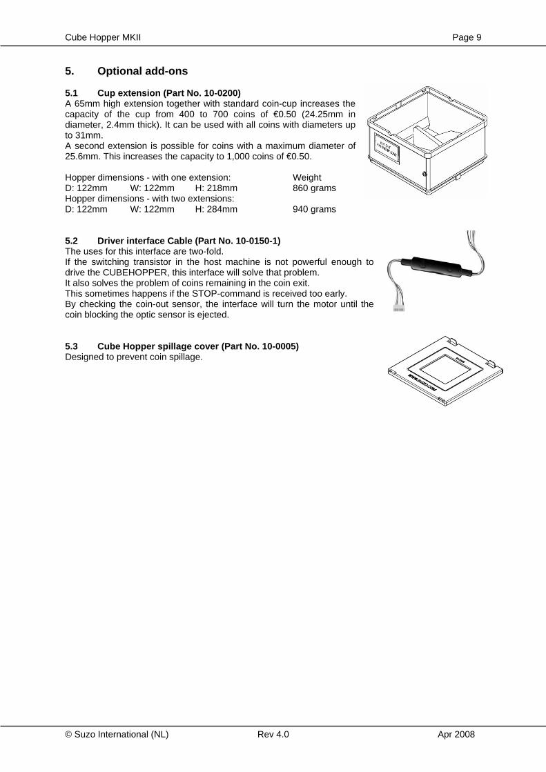
5. Optional add-ons 5.1 Cup extension (Part No. 10-0200) A 65mm high extension together with standard coin-cup increases the capacity of the cup from 400 to 700 coins of €0.50 (24.25mm in diameter, 2.4mm thick). It can be used with all coins with diameters up to 31mm. A second extension is possible for coins with a maximum diameter of 25.6mm. This increases the capacity to 1,000 coins of €0.50. Hopper dimensions - with one extension: Weight D: 122mm W: 122mm H: 218mm 860 grams Hopper dimensions - with two extensions: D: 122mm W: 122mm H: 284mm 940 grams 5.2 Driver interface Cable (Part No. 10-0150-1) The uses for this interface are two-fold. If the switching transistor in the host machine is not powerful enough to drive the CUBEHOPPER, this interface will solve that problem. It also solves the problem of coins remaining in the coin exit. This sometimes happens if the STOP-command is received too early. By checking the coin-out sensor, the interface will turn the motor until the coin blocking the optic sensor is ejected. 5.3 Cube Hopper spillage cover (Part No. 10-0005) Designed to prevent coin spillage.
Cube Hopper MKII Page 10
© Suzo International (NL) Rev 4.0 Apr 2008
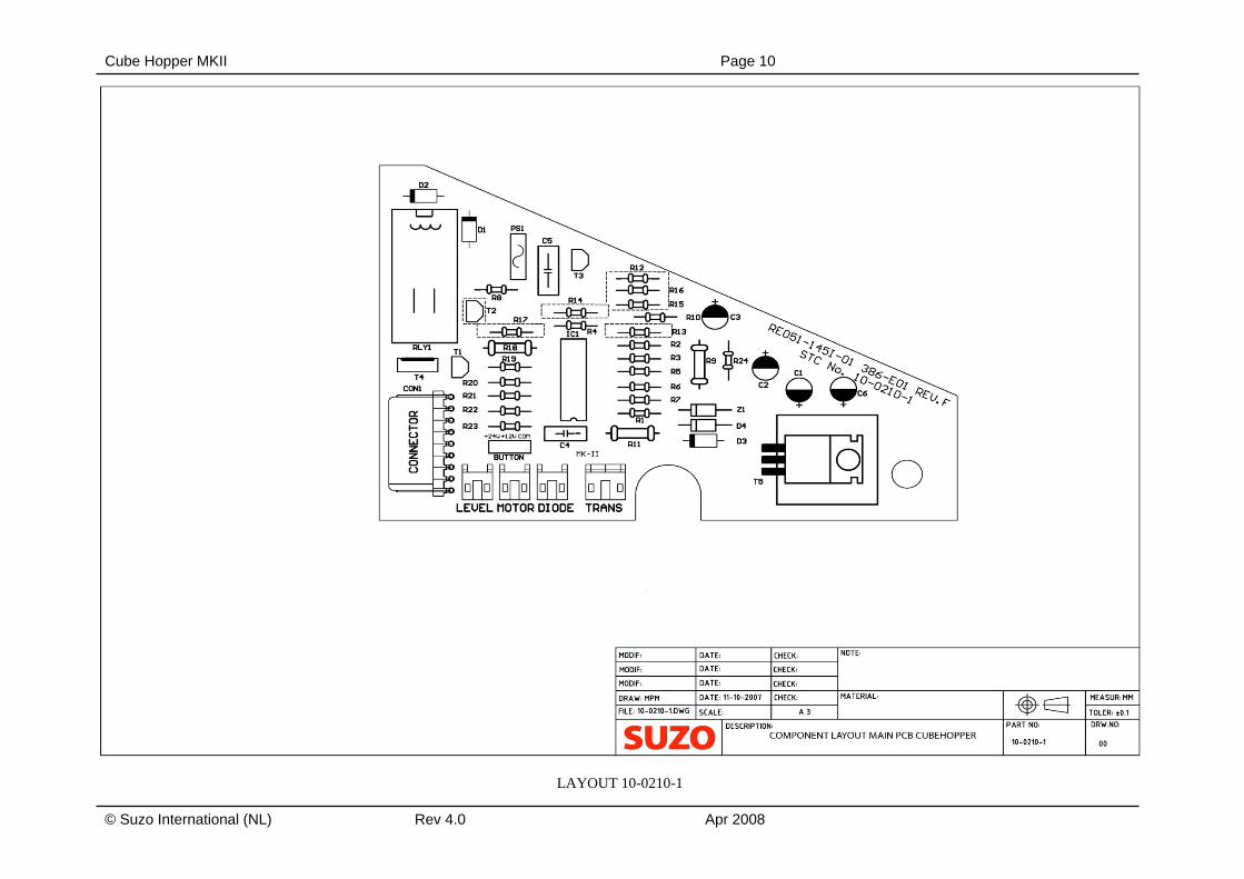
LAYOUT 10-0210-1
Cube Hopper MKII Page 11
© Suzo International (NL) Rev 4.0 Apr 2008
SCHEMATIC DIAGRAM 10-0210-1
Cube Hopper MKII Page 12
© Suzo International (NL) Rev 4.0 Apr 2008
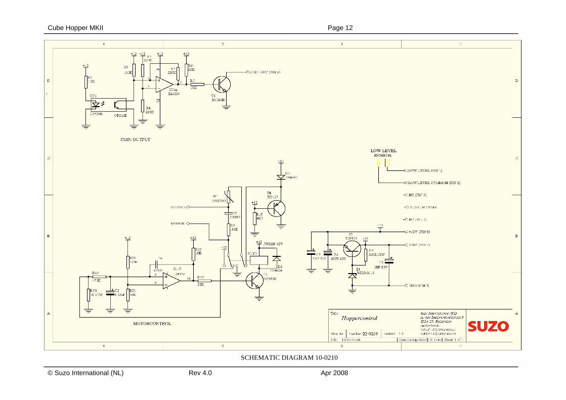
SCHEMATIC DIAGRAM 10-0210
Cube Hopper MKII Page 13
© Suzo International (NL) Rev 4.0 Apr 2008
Cube Hopper MKII Page 14
© Suzo International (NL) Rev 4.0 Apr 2008
Cube Hopper MKII Page 15
© Suzo International (NL) Rev 4.0 Apr 2008
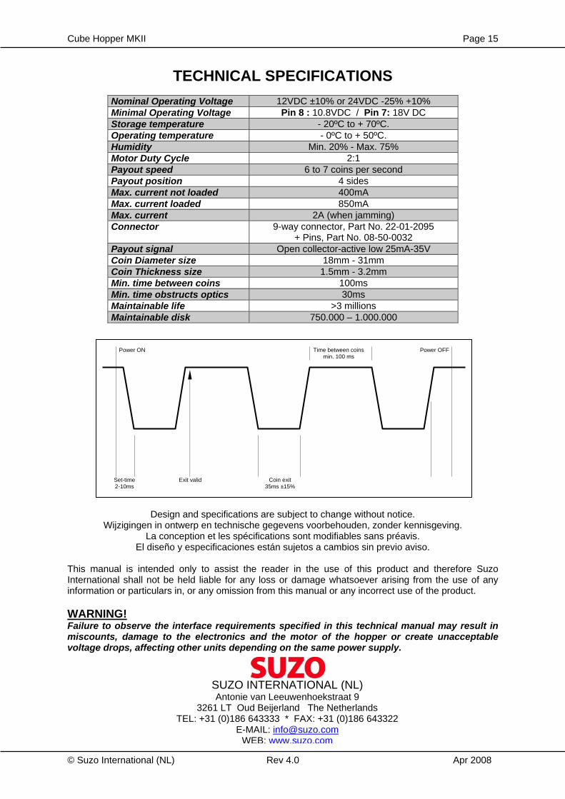
TECHNICAL SPECIFICATIONS
Nominal Operating Voltage 12VDC ±10% or 24VDC -25% +10% Minimal Operating Voltage Pin 8 : 10.8VDC / Pin 7: 18V DC Storage temperature - 20ºC to + 70ºC. Operating temperature - 0ºC to + 50ºC. Humidity Min. 20% - Max. 75% Motor Duty Cycle 2:1 Payout speed 6 to 7 coins per second Payout position 4 sides Max. current not loaded 400mA Max. current loaded 850mA Max. current 2A (when jamming) Connector 9-way connector, Part No. 22-01-2095
+ Pins, Part No. 08-50-0032 Payout signal Open collector-active low 25mA-35V Coin Diameter size 18mm - 31mm Coin Thickness size 1.5mm - 3.2mm Min. time between coins 100ms Min. time obstructs optics 30ms Maintainable life >3 millions Maintainable disk 750.000 – 1.000.000
Design and specifications are subject to change without notice. Wijzigingen in ontwerp en technische gegevens voorbehouden, zonder kennisgeving.
La conception et les spécifications sont modifiables sans préavis. El diseño y especificaciones están sujetos a cambios sin previo aviso.
This manual is intended only to assist the reader in the use of this product and therefore Suzo International shall not be held liable for any loss or damage whatsoever arising from the use of any information or particulars in, or any omission from this manual or any incorrect use of the product. WARNING! Failure to observe the interface requirements specified in this technical manual may result in miscounts, damage to the electronics and the motor of the hopper or create unacceptable voltage drops, affecting other units depending on the same power supply.
SUZO INTERNATIONAL (NL) Antonie van Leeuwenhoekstraat 9
3261 LT Oud Beijerland The Netherlands TEL: +31 (0)186 643333 * FAX: +31 (0)186 643322
E-MAIL: [email protected] WEB: www.suzo.com
Power ON Power OFF Time between coins min. 100 ms
Set-time 2-10ms
Exit valid Coin exit 35ms ±15%