Embed Size (px)
Citation preview
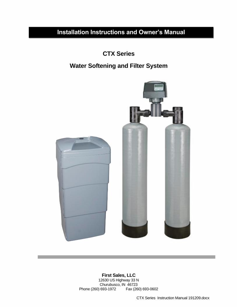
First Sales, LLC 12630 US Highway 33 N Churubusco, IN 46723
Phone (260) 693-1972 Fax (260) 693-0602
CTX Series Instruction Manual 191209.docx
CTX Series
Water Softening and Filter System
Installation Instructions and Owner’s Manual

1
Pre-installation Instructions Page 2
Installation Page 4
Bypass Valve Page 6
Media Replenishment Page 6
Display and Operation: Home Screen & Setting Time Page 7
Regeneration Page 8
Statistics Page 10
Purge History Page 12
Installer Settings Page 13
Vacation Mode & Eco Mode Page 16
Specifications Page 17
Component Parts Breakdown & List Page 18
Control Valve Parts Breakdown & List Page 19
Installation Fitting Assemblies Page 20
Troubleshooting Page 22
Warranty Page 24
Table of Contents

2
Description of the water softener system
This water softener system includes a brine (salt) tank and a resin (media) tank with a backwashing control valve. Incoming water flows into the control valve and is directed down through the carbon and then the ion exchange softening resin. The carbon absorbs chlorine to remove taste and odor and to protect the softener resin. The softener resin exchanges the hardness ions for softer ions. The softened water then returns to the control valve where it is directed into the service lines. The CTX Series water softener/filter is designed to be installed on chlorinated municipal water supplies.
Periodically the control valve will go through a regeneration cycle. The frequency of this regeneration process will depend on the size of water softener, incoming water quality and amount of water used. This cycle is factory preset to begin at 2:00 A.M. At this time the control valve will draw the brine solution out of the salt tank and flush both the accumulated hardness and excess salt to the drain. The control valve will then put fresh water back into the salt tank to make brine for the next regeneration cycle.
Water Quality
The water should be tested to determine the concentration, or levels of the items listed below:
Hardness - Hardness in drinking water is defined as those minerals that dissolve in water having a positive electrical charge (cat ions). The primary components of hardness are calcium (Ca++) and magnesium (Mg++) ions. But dissolved iron (Fe++) and manganese (Mn++) also contribute to total “adjusted” hardness. Hardness produces scale, soap scum and white mineral deposits which shorten the life of water using appliances, plumbing and fixtures. Water that has less than 1 grain of hardness is considered to be “soft” water. pH - A measurement of the acidity of the water. pH is reported on a scale from 0 to 14. Neutral water has a pH
of 7.0, lower values indicate acidic water. If your pH is below 6.8 you may consider installing an acid neutralizer
before the water softener to elevate the pH.
Iron - A naturally occurring metallic element. Iron levels in excess of 0.3 milligrams/liter (mg/l) combine with
oxygen causing orange or red (rust) stains on plumbing fixtures. Iron exists in some water sources in clear
water (ferrous) state, red water (ferric) state or bacterial form. Iron levels that exceed 2.0 mg/l require special
ion exchange resin for reduction, or if bacterial or ferric (red water) iron is present or iron level exceeds 4.0 mg/l,
an iron filter should be installed ahead of this water softener.
Manganese - A naturally occurring metallic element. Manganese levels as low as 0.05 milligrams/liter (mg/l)
can combine with oxygen to cause dark brown or black staining on fixtures. Additionally, manganese can cause
an odor in the water similar to a “rotten egg” smell. This water softener may reduce manganese as well as iron;
however, an iron filter may be required in some cases.
Tannin - A naturally occurring humic acid. Tannin is caused by water passing through decaying vegetation.
Coffee and Tea are prime examples of tannin in water. Tannin levels as low as 0.5 milligrams per liter can
cause a yellow discoloration in water. Consult your dealer for a system designed to remove both tannin and
hardness.
Hydrogen Sulfide - A naturally occurring gas. Hydrogen sulfide, more commonly referred to as sulfur gas,
causes a distinct odor similar to “rotten eggs.” Due to its gaseous nature, hydrogen sulfide must be tested at the
well site within 1 minute of drawing the sample. If sulfur is present additional equipment will be required. The
OXY3 iron filter can typically treat up to 2 milligrams per liter of sulfur gas.
Pre-installation Instructions
3
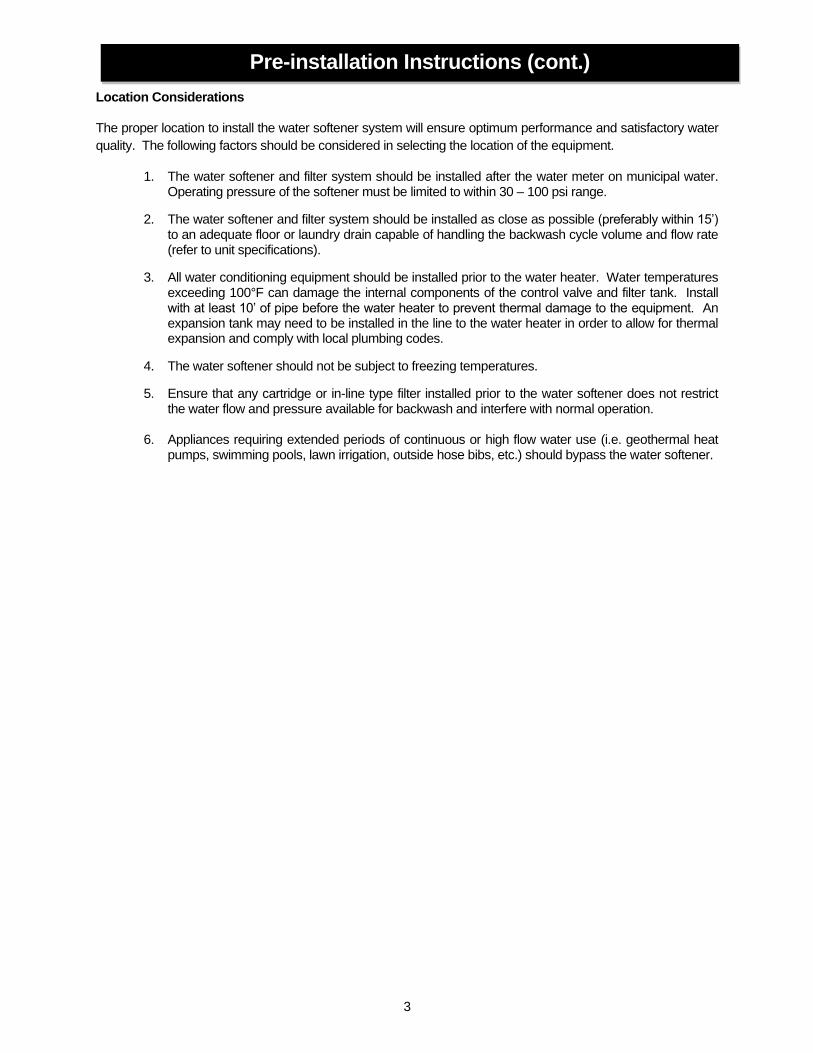
Location Considerations
The proper location to install the water softener system will ensure optimum performance and satisfactory water
quality. The following factors should be considered in selecting the location of the equipment.
1. The water softener and filter system should be installed after the water meter on municipal water. Operating pressure of the softener must be limited to within 30 – 100 psi range.
2. The water softener and filter system should be installed as close as possible (preferably within 15’) to an adequate floor or laundry drain capable of handling the backwash cycle volume and flow rate (refer to unit specifications).
3. All water conditioning equipment should be installed prior to the water heater. Water temperatures exceeding 100°F can damage the internal components of the control valve and filter tank. Install with at least 10’ of pipe before the water heater to prevent thermal damage to the equipment. An expansion tank may need to be installed in the line to the water heater in order to allow for thermal expansion and comply with local plumbing codes.
4. The water softener should not be subject to freezing temperatures.
5. Ensure that any cartridge or in-line type filter installed prior to the water softener does not restrict the water flow and pressure available for backwash and interfere with normal operation.
6. Appliances requiring extended periods of continuous or high flow water use (i.e. geothermal heat pumps, swimming pools, lawn irrigation, outside hose bibs, etc.) should bypass the water softener.
Pre-installation Instructions (cont.)
4
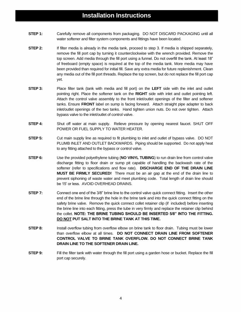
STEP 1: Carefully remove all components from packaging. DO NOT DISCARD PACKAGING until all
water softener and filter system components and fittings have been located.
STEP 2: If filter media is already in the media tank, proceed to step 3. If media is shipped separately,
remove the fill port cap by turning it counterclockwise with the wrench provided. Remove the
top screen. Add media through the fill port using a funnel. Do not overfill the tank. At least 18”
of freeboard (empty space) is required at the top of the media tank. More media may have
been provided than required for initial fill. Save any extra media for future replenishment. Clean
any media out of the fill port threads. Replace the top screen, but do not replace the fill port cap
yet.
STEP 3: Place filter tank (tank with media and fill port) on the LEFT side with the inlet and outlet
pointing right. Place the softener tank on the RIGHT side with inlet and outlet pointing left.
Attach the control valve assembly to the front inlet/outlet openings of the filter and softener
tanks. Ensure FRONT label on sump is facing forward. Attach straight pipe adapter to back
inlet/outlet openings of the two tanks. Hand tighten union nuts. Do not over tighten. Attach
bypass valve to the inlet/outlet of control valve.
STEP 4: Shut off water at main supply. Relieve pressure by opening nearest faucet. SHUT OFF
POWER OR FUEL SUPPLY TO WATER HEATER.
STEP 5: Cut main supply line as required to fit plumbing to inlet and outlet of bypass valve. DO NOT
PLUMB INLET AND OUTLET BACKWARDS. Piping should be supported. Do not apply heat
to any fitting attached to the bypass or control valve.
STEP 6: Use the provided polyethylene tubing (NO VINYL TUBING) to run drain line from control valve
discharge fitting to floor drain or sump pit capable of handling the backwash rate of the
softener (refer to specifications and flow rate). DISCHARGE END OF THE DRAIN LINE
MUST BE FIRMLY SECURED! There must be an air gap at the end of the drain line to
prevent siphoning of waste water and meet plumbing code. Total length of drain line should
be 15’ or less. AVOID OVERHEAD DRAINS.
STEP 7: Connect one end of the 3/8” brine line to the control valve quick connect fitting. Insert the other
end of the brine line through the hole in the brine tank and into the quick connect fitting on the
safety brine valve. Remove the quick connect collet retainer clip (if included) before inserting
the brine line into each fitting, press the tube in very firmly and replace the retainer clip behind
the collet. NOTE: THE BRINE TUBING SHOULD BE INSERTED 5/8” INTO THE FITTING.
DO NOT PUT SALT INTO THE BRINE TANK AT THIS TIME.
STEP 8: Install overflow tubing from overflow elbow on brine tank to floor drain. Tubing must be lower
than overflow elbow at all times. DO NOT CONNECT DRAIN LINE FROM SOFTENER
CONTROL VALVE TO BRINE TANK OVERFLOW. DO NOT CONNECT BRINE TANK
DRAIN LINE TO THE SOFTENER DRAIN LINE.
STEP 9: Fill the filter tank with water through the fill port using a garden hose or bucket. Replace the fill
port cap securely.
Installation Instructions

5
STEP 10: Add enough water to the brine tank to have a level 1” above the top step of the salt grid
(approx. 6 gal.). DO NOT ADD SALT TO THE BRINE TANK AT THIS TIME.
STEP 11: Plug the softener into an un-switched electrical outlet. Ensure control valve is in the “Service”
position (time of day is displayed on the screen {refer to page 7 for Home Screen Display}).
Place bypass valve in the “Bypass” position (refer to Figure 2, Page 6). Open main supply
valve or turn on power to pump on private well systems.
STEP 12: Using the REGEN button, advance the control valve to the backwash position (refer to pages 8
and 9 for operation).
STEP 13: Refer to Figure 2 bypass valve operation. Rotate the INLET knob of the bypass valve ¼ of the
way to Service allowing unit to fill slowly. Filling the mineral tank with the control valve in the
backwash position will force any trapped air to the drain. When all air has been purged from
the system and only water is running to the drain advance the control valve to the BRINE
DRAW cycle. Fully rotate both the inlet and outlet knobs of the bypass valve to the “Service”
position.
STEP 14: Verify that the water level in the brine tank is dropping. Allow water level to drop below the top
step of the salt grid before continuing. If the water level does not drop, refer to page 22 for
Troubleshooting. After verifying water level is dropping advance control valve to the fast rinse
position by press the NEXT button. Wait until drain water is clear or at least 1 minute and press
the NEXT button again to advance the control valve to the service position.
FIGURE 1: Brine Tank Components
Detailed Installation Instructions (cont.)

6
STEP 15: Check for leaks and correct as necessary.
STEP 16: Turn power or fuel supply back on to water heater.
STEP 17: Set the hardness & iron concentrations on the control valve (refer to timer operation for
instruction).
STEP 18: Set the current time of day on the timer (note AM and PM).
STEP 19: Add at least 40 lbs of water softener salt to the brine tank.
The activated carbon will eventually lose its adsorptive capacity and cause the chlorine taste and odor to return
to the treated water. When this occurs the exhausted carbon will have to be replaced. A wet/dry shop vacuum
can used to remove the exhausted carbon from the filter tank. CAUTION: There is a layer of gravel under the
carbon. Make sure that only activated carbon is extracted. The exhausted carbon should be replaced with the
appropriate amount of new activated carbon. Ensure that there is a minimum of 18” from the carbon to the top
of the tank to allow room for expansion during backwash cycle. The original start up and flushing procedure
should be repeated with the new carbon. An easier method is the replacement of the entire filter tank assembly.
FIGURE 2: Bypass Valve Operation
Detailed Installation Instructions (cont.)
Media Replacement

7
The active prompts displayed at the bottom of the circuit board indicate the function of each user button.
Display and Operation - Home Screen
Display and Operation - Setting Time
“Home” screen displays current time-of-day.
Press ‘SET’ button to access time set screen.
Using ‘↑’ and ‘↓’, set the current time-of day hours. Note the AM
and PM indicator and set the time accordingly.
Press ‘NEXT’ button to set current minutes.
Using ‘↑’ and ‘↓’, set the current minutes.
Press ‘NEXT’ button to save changes and return to ‘Home’ screen.
Current Time of Day
including AM or PM
indicator Flow indicator—
Flashes with
water use
Regen Tonight—
Illuminates to show
pending regeneration
status
Active prompts for
user input buttons
4 User Input
buttons
“Vacation” Mode button
and indicator light
“Eco” Mode button
and indicator light

8
The following regeneration cycles are listed in the factory programmed sequence. Each cycle in the
regeneration process may be advanced without waiting for the programmed cycle duration, for installation,
troubleshooting, or maintenance purposes.
Cycle: BRINE FILL
Cycle: SERVICE
Momentarily pressing and releasing the ‘REGEN’ button will cause the Regen Tonight indicator to illuminate on the top right side of the display. The regeneration process will begin at the next programmed time-of-regeneration (factory preset for 2:00 AM)
Press ‘NEXT’ button to advance to Backwash Cycle.
Pressing and HOLDING the ‘REGEN’ button for approximately 3 seconds will initiate an immediate regeneration. NOTE: The regeneration cycle will disable the ‘Regen Tonight’ indicator (if illuminated). The regeneration cycle will also reset the gallons remaining until next regeneration and the days override interval.
Regeneration Process
Momentarily pressing and releasing the ‘REGEN’ button again will cancel the delayed regeneration cycle.
1. The Fill and Regen indicators will be illuminated on the display. 2. The control valve will advance to the brine fill position and start adding water to the brine tank. 3. The cycle duration will begin to count down on the display once the control valve is in the proper position. The cycle duration is dictated by either the programmed salt dosage setting or the ECO calculated salt dosage (if activated). 4. This cycle occurs 90 minutes prior to the scheduled regeneration time. (Regeneration is factory preset at 2:00 AM, so Brine Fill cycle would occur at 12:30 AM) 5. Treated (soft) water is still available during this cycle.
1. The Service and Regen indicators will be illuminated on the display. 2. The control valve will advance to the Service (Home) position. 3. The cycle duration will begin to count down on the display once the control valve is in the proper position. 4. This cycle allows the fresh water that has been added to the brine tank sufficient time to dissolve the salt to make saturated brine. 5. Treated (soft) water is still available during this cycle.
Press ‘NEXT’ button to advance to Service Cycle.
9
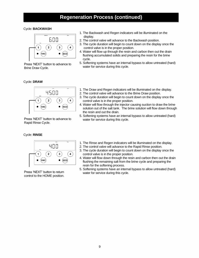
Cycle: BACKWASH
Cycle: DRAW
Cycle: RINSE
1. The Backwash and Regen indicators will be illuminated on the display. 2. The control valve will advance to the Backwash position. 3. The cycle duration will begin to count down on the display once the control valve is in the proper position. 4. Water will flow up through the resin and carbon then out the drain flushing accumulated solids and preparing the resin for the brine cycle. 5. Softening systems have an internal bypass to allow untreated (hard) water for service during this cycle.
Press ‘NEXT’ button to advance to Brine Draw Cycle.
1. The Draw and Regen indicators will be illuminated on the display. 2. The control valve will advance to the Brine Draw position. 3. The cycle duration will begin to count down on the display once the control valve is in the proper position. 4. Water will flow through the injector causing suction to draw the brine solution out of the salt tank. The brine solution will flow down through the resin and out the drain. 5. Softening systems have an internal bypass to allow untreated (hard) water for service during this cycle. Press ‘NEXT’ button to advance to
Rapid Rinse Cycle.
1. The Rinse and Regen indicators will be illuminated on the display. 2. The control valve will advance to the Rapid Rinse position. 3. The cycle duration will begin to count down on the display once the control valve is in the proper position. 4. Water will flow down through the resin and carbon then out the drain flushing the remaining salt from the brine cycle and preparing the resin for the softening process. 5. Softening systems have an internal bypass to allow untreated (hard) water for service during this cycle. Press ‘NEXT’ button to return
control to the HOME position.
Regeneration Process (continued)
10
Statistics
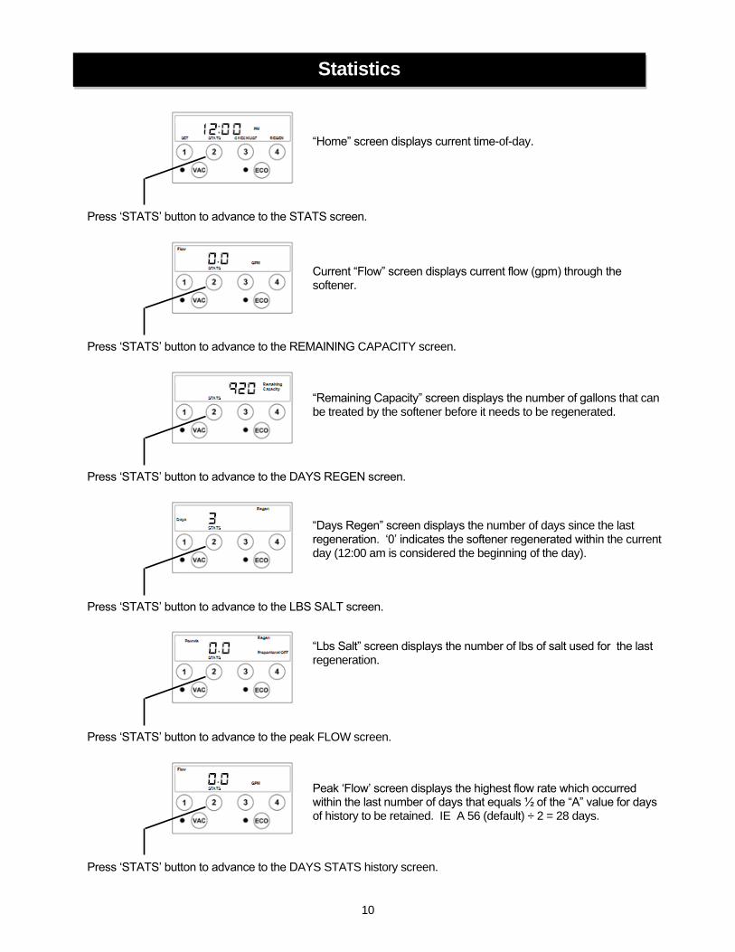
“Home” screen displays current time-of-day.
Press ‘STATS’ button to advance to the STATS screen.
Current “Flow” screen displays current flow (gpm) through the softener.
Press ‘STATS’ button to advance to the REMAINING CAPACITY screen.
“Remaining Capacity” screen displays the number of gallons that can be treated by the softener before it needs to be regenerated.
Press ‘STATS’ button to advance to the DAYS REGEN screen.
“Days Regen” screen displays the number of days since the last regeneration. ‘0’ indicates the softener regenerated within the current day (12:00 am is considered the beginning of the day).
Press ‘STATS’ button to advance to the LBS SALT screen.
“Lbs Salt” screen displays the number of lbs of salt used for the last regeneration.
Press ‘STATS’ button to advance to the peak FLOW screen.
Peak ‘Flow’ screen displays the highest flow rate which occurred within the last number of days that equals ½ of the “A” value for days of history to be retained. IE A 56 (default) ÷ 2 = 28 days.
Press ‘STATS’ button to advance to the DAYS STATS history screen.
11
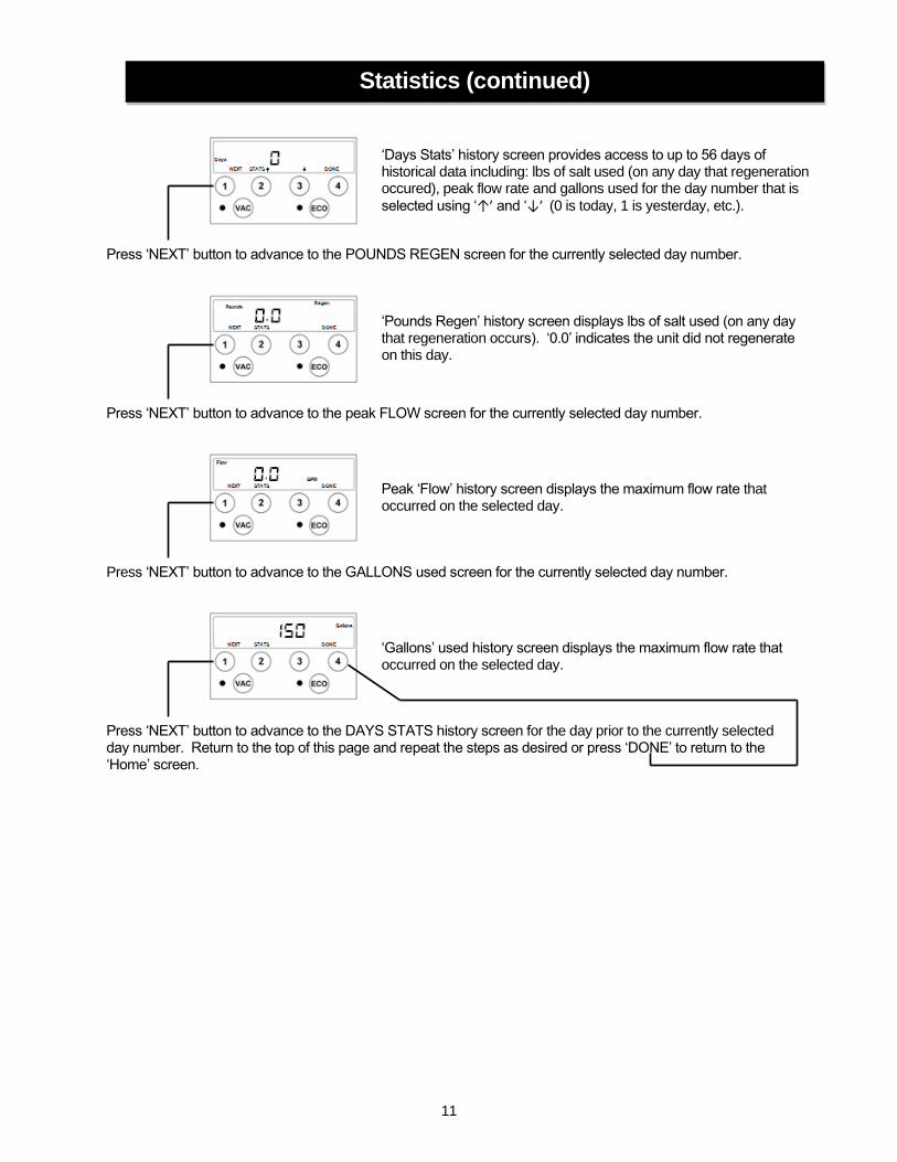
‘Days Stats’ history screen provides access to up to 56 days of historical data including: lbs of salt used (on any day that regeneration occured), peak flow rate and gallons used for the day number that is
selected using ‘↑’ and ‘↓’ (0 is today, 1 is yesterday, etc.).
Press ‘NEXT’ button to advance to the POUNDS REGEN screen for the currently selected day number.
‘Pounds Regen’ history screen displays lbs of salt used (on any day that regeneration occurs). ‘0.0’ indicates the unit did not regenerate on this day.
Press ‘NEXT’ button to advance to the peak FLOW screen for the currently selected day number.
Peak ‘Flow’ history screen displays the maximum flow rate that occurred on the selected day.
Press ‘NEXT’ button to advance to the GALLONS used screen for the currently selected day number.
‘Gallons’ used history screen displays the maximum flow rate that occurred on the selected day.
Press ‘NEXT’ button to advance to the DAYS STATS history screen for the day prior to the currently selected day number. Return to the top of this page and repeat the steps as desired or press ‘DONE’ to return to the ‘Home’ screen.
Statistics (continued)

12
If it is ever necessary to purge the stored historical data it can be accomplished by performing the steps below
from the home screen:
“Home” screen displays current time-of-day.
Press and hold ‘STATS’ button to advance to the STATS FLOW RATE screen.
Purge History
Current “Flow” screen displays current flow (gpm) through the softener.
Continue holding the ‘STATS’ button while simultaneously pressing and holding the VAC and ECO buttons. The VAC and ECO lights will be lit breifly and then go out and the display will return to the HOME screen to confirm the data has been purged.
“Home” screen displays current time-of-day.

13
The installer settings provide access to the water softener cycle times. The factory settings have been
programmed for maximum efficiency. Altering the factory programmed cycles will affect the softeners
performance. NOTE: Extreme caution must be taken when adjusting the water softener cycles.
Decreasing a cycle time or completely deleting the cycle may cause the softener to stop functioning.
“Home” screen displays current time-of-day.
Press and HOLD ‘CHECKLIST’ button for approximately 3 seconds to access installer settings.
Ensure the Iron indicator is illuminated on the left side of the
display and using the ‘↑’ and ‘↓’ buttons set the incoming iron
concentration. NOTE: While a water softener can be reasonably expected to remove small amounts of clear water iron, for best performance an iron filter should be considered.
Press ‘NEXT’ button to set incoming HARDNESS level.
Ensure the Hardness indicator is illuminated on the left side of
the display and using the ‘↑’ and ‘↓’ buttons set the incoming
hardness level.
NOTE: This softener is set to calculate hardness as grains per gallon (gpg). If your water hardness is reported in milligrams per liter (mg/l) or parts per million (ppm) divide these results by 17.1 to convert to grains per gallon.
Press ‘NEXT’ button to set regeneration DAYS OVERRIDE interval
Using ‘↑’ and ‘↓’, set the desired day override interval. The
regeneration day override function will cause the softener to regenerate after a designated period of no regeneration cycles. The override interval will reset after every regeneration cycle whether initiated manually or by volume. The day override function will be disabled if the VACATION mode is active.
Press ‘NEXT’ button to set REGENERATION TIME hours.
Installer Settings – Cycles
Ensure the Regen Time indicator is illuminated. Using ‘↑’ and ‘↓’, set the desired time of regeneration hours. Note the AM and PM indicator and set the time accordingly.
Press ‘NEXT’ button to set REGENERATION TIME minutes.

14
CAUTION: Changing the cycle durations will affect the water softener’s performance
and efficiency. The following settings should only be altered by a knowledgeable
water treatment professional.
Ensure the Regen Time indicator is illuminated. Using ‘↑’ and ‘↓’, set the desired time of regeneration minutes.
Press ‘NEXT’ button to set PROPORTIONAL BRINING.
Press ‘NEXT’ button to set cycle #1 duration.
Using ‘↑’ and ‘↓’, the Proportional Brining function can be set to ON
or OFF. This feature can also be manually toggled on or off with the ECO button on the face of the front panel. (See additional information on Proportional Brining in the ECO section of the instruction manual.)
Press ‘NEXT’ button to set cycle #2 duration.
Installer Settings – Cycles (continued)
Ensure the Pounds and Fill indicators are illuminated. Using ‘↑’ and
‘↓’, set the desired amount of salt to be used during the regeneration
cycle.
Ensure the Service and Minutes indicators are illuminated. Using ‘↑’ and ‘↓’, set the desired length of time to allow fresh water in brine
tank to dissolve salt to make saturated brine. NOTE: Minimum recommended time is 1 hour 30 minutes.
Press ‘NEXT’ button to set cycle #3 duration.
Ensure the Backwash and Minutes indicators are illuminated. Using
‘↑’ and ‘↓’, set the desired length of time for BACKWASH cycle
Press ‘NEXT’ button to set cycle #4 duration.
Ensure the Draw and Minutes indicators are illuminated. Using ‘↑’ and ‘↓’, set the desired length of time for BRINE DRAW cycle.
Press ‘NEXT’ button to set cycle #5 duration.

15
Ensure the Rinse and Minutes indicators are illuminated. Using
‘↑’ and ‘↓’, set the desired length of time for RINSE cycle.
After all cycles have been set press either ‘NEXT’ or ‘DONE’ button to return to Home Screen.
Installer Settings – Cycles (continued)

16
Once activated, the vacation mode will prevent the water softener from regenerating. This may be
used if the house will not be occupied for an extended period of time. The vacation mode is initiated by pressing
the VAC button on the front panel. There will be a 30 minute delay from the time the button is pressed until the
vacation mode is active to allow time for last minute water use.
The vacation mode will automatically deactivate once the water softener detects normal water use.
The revolutionary ECO mode is a forward-looking feature that uses water usage history and a process
called proportional brining to ensure adequate softening capacity for future estimated water use. The water
softener stores historical daily water use data. If the next day’s anticipated water use requires more softening
capacity than is currently available, the softener will initiate a regeneration process using a fractional portion of
the programmed salt setting. This partial salt regeneration recovers only the depleted portion of the softening
capacity. This proportional regeneration will save in both salt consumption and water use by using lower salt
settings and fewer regeneration cycles.
Vacation Mode
The VACATION mode may be activated or deactivated by
pressing the VAC button on the front panel. The red LED
light will be illuminated when the vacation mode is
activated.
ECO Mode
The ECO mode may be activated or deactivated by
pressing the ECO button on the front panel. The green
LED light will be illuminated when the ECO mode is
activated.
17
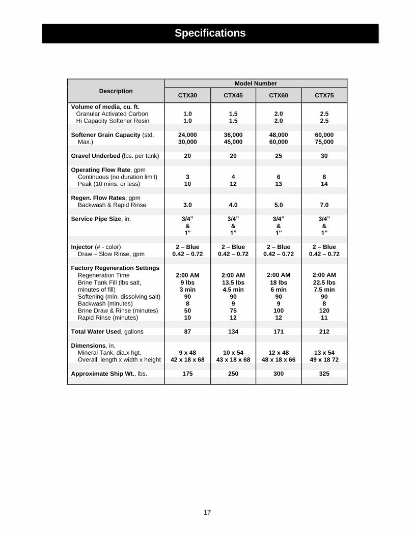
Description
Model Number
CTX30 CTX45 CTX60 CTX75
Volume of media, cu. ft. Granular Activated Carbon Hi Capacity Softener Resin
1.0 1.0
1.5 1.5
2.0 2.0
2.5 2.5
Softener Grain Capacity (std. Max.)
24,000 30,000
36,000 45,000
48,000 60,000
60,000 75,000
Gravel Underbed (lbs. per tank) 20 20 25 30 Operating Flow Rate, gpm Continuous (no duration limit) 3 4 6 8 Peak (10 mins. or less) 10 12 13 14 Regen. Flow Rates, gpm Backwash & Rapid Rinse 3.0 4.0 5.0 7.0 Service Pipe Size, in. 3/4”
& 1”
3/4” & 1”
3/4” & 1”
3/4” & 1”
Injector (# - color) Draw – Slow Rinse, gpm
2 – Blue 0.42 – 0.72
2 – Blue 0.42 – 0.72
2 – Blue 0.42 – 0.72
2 – Blue 0.42 – 0.72
Factory Regeneration Settings
Regeneration Time 2:00 AM 2:00 AM 2:00 AM 2:00 AM
Brine Tank Fill (lbs salt, minutes of fill)
9 lbs 3 min
13.5 lbs 4.5 min
18 lbs 6 min
22.5 lbs 7.5 min
Softening (min. dissolving salt) 90 90 90 90 Backwash (minutes) 8 9 9 8 Brine Draw & Rinse (minutes) 50 75 100 120 Rapid Rinse (minutes) 10 12 12 11 Total Water Used, gallons 87 134 171 212 Dimensions, in. Mineral Tank, dia.x hgt. 9 x 48 10 x 54 12 x 48 13 x 54 Overall, length x width x height 42 x 18 x 68 43 x 18 x 68 48 x 18 x 66 49 x 18 72 Approximate Ship Wt., lbs. 175 250 300 325
Specifications

18
Ref Description Model Number
CTX30 CTX45 CTX60 CTX75
1 O-ring, -323 OR323 OR323 OR323 OR323
2 Connector Nut C102 C102 C102 C102
3 Split Ring Retainer C101 C101 C101 C101
A Dual Tank Connector DTC204-8 DTC204-8 DTC204-8 DTC204-8
B Elect. Metered valve
w/bypass CTX30 Vlv Assy
W/BP CTX45 Vlv Assy
W/BP CTX60 Vlv Assy
W/BP CTX75 Vlv Assy
W/BP
C Distributor Head w/Fill Port FP207 FP207 FP207 FP207
Screen for Fill Port FPS101 FPS101 FPS101 FPS101
D Distributor D100S-48 D100S-54 D100S-48 D100S-54
E Media Tank MTP0948GR MTP1054GR MTP1248GR MTP1354GR
F Brine Tank Assy. BTSQ1833ASSY BTSQ1833ASSY BTSQ1833ASSY BTSQ1833ASSY
G Overflow Fitting BT-OVERFLO BT-OVERFLO BT-OVERFLO BT-OVERFLO
H Safety Brine Valve SBV14ASSY SBV14ASSY SBV14ASSY SBV14ASSY
I Salt Platform BTSG18SQ BTSG18SQ BTSG18SQ BTSG18SQ
J Bypass BP 213 BP 213 BP 213 BP 213
K Carbon Media A10 (1)A10
(1) A05P (2) A10
(2) A10 (1) A05P
L Resin H10 (1) H10
(1) H05P (2) H10
(2) H10 (1) H05P
M ¼” x 1/8” Gravel QC20 QC20 (1.25) QC20 (1.5) QC20
-NA- Top Screen FHS101 FHS101 FHS101 FHS101
-NA- Distributor Adapter SA900 SA900 SA900 SA900
Component Parts Breakdown
1
2 3
A
B
C C
D D
E E
K
L
M M
J
F
G
H
I

19
REF # Part Number Description
REF # Part Number Description
1 FCC-950 Front Cover
18
EBA975 ¾” NPT Elbow Assembly (2 req’d)
2 PCB-3486 Circuit Board (specify unit model) EBA900 1” NPT Elbow Assembly (2 req’d)
3 DC-12 DC Adaptor with cord EBA915 1 ½” NPT Elbow Assembly (2 req’d)
4 BV910 Brine Valve Assembly 19 TAF131 Tank Attachment
5 CAB945 Piston and Rod Assembly 20 TN101 Tank Nut
6 TSS900 Seal Cartridge Assembly 21 VG145 Venturi Gasket
7 RVS932 Injector Assembly w/o-rings 22 VP145 Venturi Plate
8 FS165 Injector Filter Screen
23 VB145 Venturi Hex Head Bolt, 18-8 SS 1/4-20 x 1/2"
9 OR342 Valve to Tank Adaptor O-Ring (replaces OR344)
24 QCF987 Quick Connect Flow Assembly
10 OR337 Tank O-ring 25 HPC-075 Hair Pin Clip
11 FC902 Drain Fitting, 3/4” MNPT (NEW)
26 HEH138 Hall Effect Sensor Wire Harness FC901 Drain Fitting, 1/2” FPT (OLD)
12 FC103 Drain Fitting Retainer Clip
27 WH137 Power wire assembly with nut and lock washer
13 FM205 Turbine Flow Meter 28 UQS-100 Seal for Quick Connect Flow Assy.
14 MCA945 Motor and Cam Assembly (includes nut micro switches)
29 OR255 O-ring, 255, Pilot Tube O-ring
15 7779K420-MICRO Micro Switch (2 required)
NOT SHOWN
GL463412 Drain Fitting, Hose Barb, 90° Elbow, 3/4" FPT x 1/2" barb (NEW)
16 EBA910 Optional 90° Bypass Elbow
12338 Drain Fitting, Hose Barb, 90° Elbow, 1/2" MNPT x 1/2" barb (OLD)
17 BP 213 Bypass Valve FHS101 Top Screen (-HE Suffix Only)
SA900 Distributor Adaptor (-HE Suffix Only)
Control Valve Parts Breakdown

20
1” PVC MALE NPT ELBOW 90 DEGREE BYPASS ELBOW
Ref Part # Description Qty Ref Part # Description Qty
EBA900 1” Elbow Assembly 1*
EBA910 90° Bypass Elbow
Assembly 1*
1 EB100 1” Elbow 1
1 EB175 Bypass Elbow 1
2 OR323 O-ring, -323 1
2 OR323 O-ring, -323 1
3 C 101 Split Ring Retainer 1
3 C 101 Split Ring Retainer 1
4 C 102 Connector Nut
1
4 C 102 Connector Nut
1
1-1/2” PVC MALE NPT ELBOW ¾” PVC MALE NPT ELBOW
Ref Part # Description Qty Ref Part # Description Qty
EBA915 1-1/2” Elbow Assembly 1*
EBA975 3/4” Elbow Assembly 1*
1 EB150 1.5” Elbow 1
1 EB750 3/4” Elbow 1
2 OR323 O-ring, -323 1
2 OR323 O-ring, -323 1
3 C 101 Split Ring Retainer 1
3 C 101 Split Ring Retainer 1
4 C 102 Connector Nut 1
4 C 102 Connector Nut 1
(*2 required)
Installation Fitting Assemblies
1
2
4
3
1
1
1
4
4 4
3
3
3
2
2
2
(*2 required) (*2 required)
(*2 required)

21
1” STRAIGHT FITTING
Ref Part # Description Qty
TC204-1 1” Straight Fitting Assembly 1*
1 TC101-1 1” Straight 1
2 OR323 O-ring, -323 (not shown) 1
3 C 101 Split Ring Retainer (not shown) 1
4 C 102 Connector Nut 1
3/4” QUICK CONNECT
Ref Part # Description Qty
QFNCR4 3/4” Quick Connect Assembly
1*
Installation Fitting Assemblies (cont.)
1 4
(*2 required)
(*2 required)

22
PROBLEM CAUSE SOLUTION
1. Softener fails to regenerate
A. Electrical service to unit has been interrupted
A. Ensure permanent electrical service to unit (switch, circuit breaker, plug, etc.)
B. Faulty timer motor or micro switch B. Replace defective component
C. Defective drive motor or micro switch
C. Replace defective component
D. Improper unit configuration D. Meter cable unplugged (FSM) or no
tabs pushed outward on the skipper wheel (FS)
2. Softener delivers hard water
A. Bypass valve is open A. Close bypass valve
B. No salt in brine tank or salt is “bridged”
B. Verify salt is not “bridged” and add salt to brine tank and maintain salt level above water level
C. Injectors or screen plugged C. Clean or replace injectors and
screen
D. Insufficient water flowing into brine tank
D. Check brine tank fill time and clean brine line flow control
E Leak at distributor tube E. Check length of distributor tube and
pilot tube o-ring
F. Internal valve leak F. Replace piston and seals/spacer kit
G. Flow meter obstructed G. Clean flow meter
H. Softener not regenerating H. See Problem 1 above
I. Flow rate exceeds rated service flow I. Verify the softener is properly sized
3. Unit uses too much salt A. Improper configuration
A. Verify proper salt setting, meter setting (FSM), skipper wheel setting (FS)
B. Excessive water in brine tank B. See Problem # 7
4. Loss of water pressure
A. Softener too small for application A. Check application requirements and
resize water softener as required
B. Foreign material buildup in plumbing system or water softener
B. Clean or replace plumbing, as necessary, additional treatment equipment may be required
5. Loss of resin through drain line
A. Air in water system
A1. Check for low water table conditions in well
A2. Check for positive seal on brine line connections
B. Drain line flow control is too large B. Ensure proper drain line flow control
is installed
6. Iron in softened water
A. Iron exceeds recommended parameters or iron bacteria is present
A. Test incoming water supply and install OXY Series iron filter prior to softener, as needed
B. Iron fouled resin
B. Check and lengthen backwash, brine draw and brine fill times. Increase frequency of regeneration. Use resin cleaner in brine tank.
7. Excessive water level in brine tank
A. Restricted drain flow control A. Clean drain line flow control
B. Drain line too long or installed overhead or restricted
B. Verify drain line is not restricted or improperly installed
C. Vinyl drain line was used C. Replace drain line with rigid or semi-
rigid material with no kinks and as few elbows as possible
D. Brine valve sticking (soft water) D. Replace brine valve assembly
E. Injector/screen plugged (hard water) E. Clean or replace injectors and
screen
F. Improper configuration F. Verify the salt setting
G. Either end of the brine line is not fully inserted
G. Ensure brine line in inserted at least 5/8” into fittings
Troubleshooting

23
PROBLEM CAUSE SOLUTION
8. Salty water after regeneration
A. Injectors or screen plugged A. Clean or replace injectors and
screen
B. Restricted drain flow control B. Clean drain line flow control
C. Brine valve sticking C. Replace brine valve assembly
D. Brine tank is overfilled D. See Problem # 7
E. Rinse cycle too short E. Lengthen rinse cycle
9. Water leaks to drain continuously
A. Foreign material in control valve A. Remove and inspect piston and
seal kit. Replace as necessary
B. Drive motor stopped during regeneration cycle
B. Check for obstruction in piston and seals. Replace drive motor. Inspect condition of power head gears
C. Control valve continuously cycling C. See Problem #10
D. Internal valve seal leak D. Replace seals and/or piston
10. Control valve continuously cycling A. Faulty homing switch A. Replace homing switch
Troubleshooting (continued)

24
WARRANTY – First Sales, LLC. warrants this water conditioner against any defects that are due to faulty material or workmanship during the warranty period. This warranty does not include damage to the product resulting from accident, neglect, misuse, misapplication, alteration, installation or operation contrary to printed instructions, or damage caused by freezing, fire, flood, or Acts of God. From the original date of consumer purchase, we will repair or replace, at our discretion, any part found to be defective within the warranty period described below. Purchaser is responsible for any shipping cost to our facility and any local labor charges.
• One year on the entire water conditioner
• Five years on the control valve
• Ten years on the mineral tank GENERAL CONDITIONS – Should a defect or malfunction occur, contact the dealer that you purchased the product from. If you are unable to contact the dealer, contact First Sales, LLC. @ (260)693-1972. We will require a full description of the problem, model number, date of purchase, and selling dealer’s business name and address. We assume no warranty liability in connection with this water conditioner other than specified herein. This warranty is in lieu of all other warranties, expressed or implied, including warranties of fitness for a particular purpose. We do not authorize any person or representative to assume for us any other obligations on the sale of this water conditioner.
FILL IN AND KEEP FOR YOUR RECORDS ______________________________________________________________________ Original Purchaser Date of Purchase Model #
Address of Original Installation City State
Dealer Purchased From Dealer Address City State
First Sales, LLC. 12630 U.S. 33 North, Churubusco, IN 46723
TEN YEAR LIMITED WARRANTY