Embed Size (px)
Citation preview
CTP Dispatcher and IP Client User Manual V2.14 Page 1
CTP Dispatcher and IP Client User Manual V2.14 Page 2
Contents Introducing the ConvergenceTP M2M modules .......................................................................................................................... 3
Preface: ........................................................................................................................................................................................ 4
Figure 1 ..................................................................................................................................................................................... 4
Pre-install requirements .............................................................................................................................................................. 5
Installation .................................................................................................................................................................................... 5
Figure 2 ..................................................................................................................................................................................... 5
Dispatcher Installer – Installed on the same machine as Ocularis base .................................................................................. 6
IP Client Installer – Installed on any PC in the same network as Ocularis. .............................................................................. 7
Dispatcher Table Explained .......................................................................................................................................................... 8
A – Static TCP/IP ports used by the Dispatcher .................................................................................................................... 8
B - Processing Defaults. (Optional features. Defaults to Dynamic matrix and TCP/IP) ........................................................ 8
C- Procedure Settings (Optional feature requires ESE to be installed) ................................................................................ 9
D - Dispatcher Task List ...................................................................................................................................................... 10
E – Dispatcher Task List Entry and Editing Tools ............................................................................................................... 11
F - Ocularis Client Login information .................................................................................................................................. 11
H - Simulator (optional feature) ......................................................................................................................................... 12
I - Settings ........................................................................................................................................................................... 13
IP Client Configuration GUI ........................................................................................................................................................ 14
Troubleshooting ......................................................................................................................................................................... 15
Procedure Manager ........................................................................................................................................................... 15
For the Dispatcher .............................................................................................................................................................. 15
Dispatcher Output commands not working ....................................................................................................................... 15
For the IP Client .................................................................................................................................................................. 15
Appendix A: Dispatcher and IP Client TCP/IP ports used ........................................................................................................... 16
Appendix B: Dispatcher flow diagram using the Dispatcher simulator ..................................................................................... 17
Appendix C: Dispatcher Log file sample ..................................................................................................................................... 18
Appendix D: Output Command Interface .................................................................................................................................. 19
Appendix E: CTP License Server Control Panel ........................................................................................................................... 20
Loading a new CTP License File .............................................................................................................................................. 20
Contact Information ................................................................................................................................................................... 21

CTP Dispatcher and IP Client User Manual V2.14 Page 3
Introducing the ConvergenceTP M2M modules
Machine to Machine (M2M) Modules for the Security and Video Surveillance Market.
The next technology wave for the video surveillance market is for it to become the head end for all IP enabled appliances and sensors in the customer enterprise. The migration is obvious as the video surveillance infrastructure is already in place and has the bandwidth, IP enabled connectivity and trained personnel to lead this technology consolidation. The video surveillance system is the best component in the IP enabled enterprise for analyzing and storing the massive amounts of data that will be received as these technologies consolidate to a single head end monitoring and management topology. Convergence To Pixels (ConvergenceTP) was founded on this principle and is keenly focused on delivering this vision.
IP enabled appliances such as IP Cameras, Access Control and Point of Sale Terminals along with IP enabled sensors such as PLC Controllers and RFID tags are now critical components of a new era of IP enabled Smart Systems and Businesses. Technology users realize that in order to truly have Real-time awareness and response in their enterprise all of these IP enabled devices and appliances need to be connected. These forward thinking technology users realize that the resultant collective awareness made possible by bringing all of the information from their IP devices together is far greater than just the sum of the individual parts. The ConvergenceTP Machine To Machine connectivity modules and rule engines compliment the already feature rich OnSSI Video Management System by providing users with the key components needed to enter this new era of IP Enabled Smart Systems.
ConvergenceTP M2M Remote OnSSI Client Module Feature Summary:
1) Wide range of PLC and IP Appliance interface options available. 2) Supports an unlimited number remotely connected and completely remotely controlled video clients 3) Remote clients can be set to fixed screen layout, or set to dynamically adjust the screen layout. 4) M2M events can easily be setup to send “Generic Events” into Ocularis. 5) The fixed screen layout provides video matrix functionality to switch camera feeds within the fixed layout. 6) The dynamic screen layout option allows the remote IP client to adjust the view layout based on camera count. 7) The remote IP Client can be set to full screen or windowed mode, supports PTZ presets and can be displayed or
minimized to the tray all completely under control of TCP/IP or UDP commands sent over the network. 8) The easy to use GUI module allows users to define rules and set a variety of modes such as, from single
command to single IP Client, or from single command to multiple IP Client broadcast functionality. 9) The GUI module allows the user to configure what camera goes to what view pane in the remote client as well
as an optional dwell time for the event to be shown. 10) ConvergenceTP offers a comprehensive API for the M2M modules which provides VARs, 3rd party IP appliance
and IP sensor solution providers the ability to create their own interfaces to the ConvergenceTP M2M IP Client.
CTP Dispatcher and IP Client User Manual V2.14 Page 4
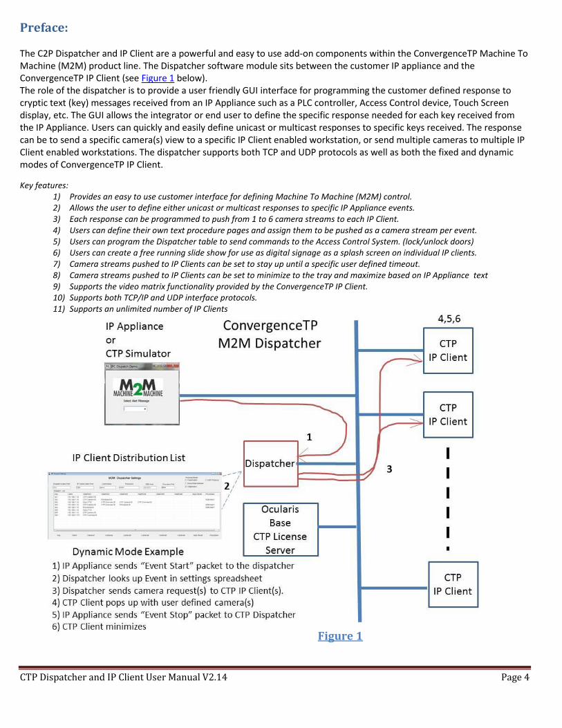
Preface: The C2P Dispatcher and IP Client are a powerful and easy to use add-on components within the ConvergenceTP Machine To Machine (M2M) product line. The Dispatcher software module sits between the customer IP appliance and the ConvergenceTP IP Client (see Figure 1 below). The role of the dispatcher is to provide a user friendly GUI interface for programming the customer defined response to cryptic text (key) messages received from an IP Appliance such as a PLC controller, Access Control device, Touch Screen display, etc. The GUI allows the integrator or end user to define the specific response needed for each key received from the IP Appliance. Users can quickly and easily define unicast or multicast responses to specific keys received. The response can be to send a specific camera(s) view to a specific IP Client enabled workstation, or send multiple cameras to multiple IP Client enabled workstations. The dispatcher supports both TCP and UDP protocols as well as both the fixed and dynamic modes of ConvergenceTP IP Client.
Key features: 1) Provides an easy to use customer interface for defining Machine To Machine (M2M) control. 2) Allows the user to define either unicast or multicast responses to specific IP Appliance events. 3) Each response can be programmed to push from 1 to 6 camera streams to each IP Client. 4) Users can define their own text procedure pages and assign them to be pushed as a camera stream per event. 5) Users can program the Dispatcher table to send commands to the Access Control System. (lock/unlock doors) 6) Users can create a free running slide show for use as digital signage as a splash screen on individual IP clients. 7) Camera streams pushed to IP Clients can be set to stay up until a specific user defined timeout. 8) Camera streams pushed to IP Clients can be set to minimize to the tray and maximize based on IP Appliance text 9) Supports the video matrix functionality provided by the ConvergenceTP IP Client. 10) Supports both TCP/IP and UDP interface protocols. 11) Supports an unlimited number of IP Clients
Figure 1
CTP Dispatcher and IP Client User Manual V2.14 Page 5
Pre-install requirements The PC/Server hosting Dispatcher needs to be relatively current with Windows Updates. Any PC hosting the IP Client will need to have the OnSSI Client installed. During the install temporarily disable any antivirus SW and drop the firewalls.
During the install you will need the ability to temporarily set UAC to off. Administrator account for use when installing CTP software Execute any M2M installer using “Run as Administrator” OnSSI Client “Basic” login account with valid credentials Ocularis Base version 5.0 or higher. Note: If the Dispatcher will be used to output commands to an access control system, or other IP appliance, then the C2P Proxy for that IP appliance will also need to be installed. See also Appendix D: Output Command Interface
Installation
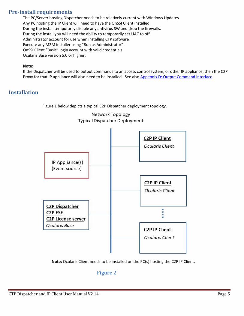
Figure 1 below depicts a typical C2P Dispatcher deployment topology.
Note: Ocularis Client needs to be installed on the PC(s) hosting the C2P IP Client.
Figure 2
CTP Dispatcher and IP Client User Manual V2.14 Page 6
Dispatcher Installer – Installed on the same machine as Ocularis base
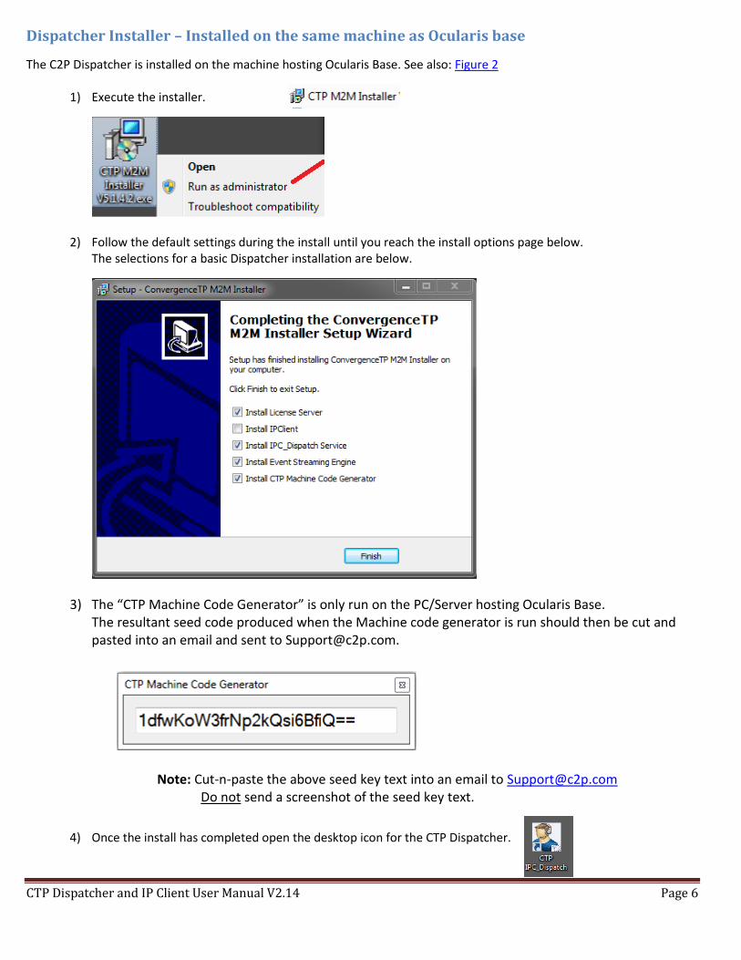
The C2P Dispatcher is installed on the machine hosting Ocularis Base. See also: Figure 2
1) Execute the installer.
2) Follow the default settings during the install until you reach the install options page below. The selections for a basic Dispatcher installation are below.
3) The “CTP Machine Code Generator” is only run on the PC/Server hosting Ocularis Base. The resultant seed code produced when the Machine code generator is run should then be cut and pasted into an email and sent to [email protected].
Note: Cut-n-paste the above seed key text into an email to [email protected] Do not send a screenshot of the seed key text.
4) Once the install has completed open the desktop icon for the CTP Dispatcher.
CTP Dispatcher and IP Client User Manual V2.14 Page 7
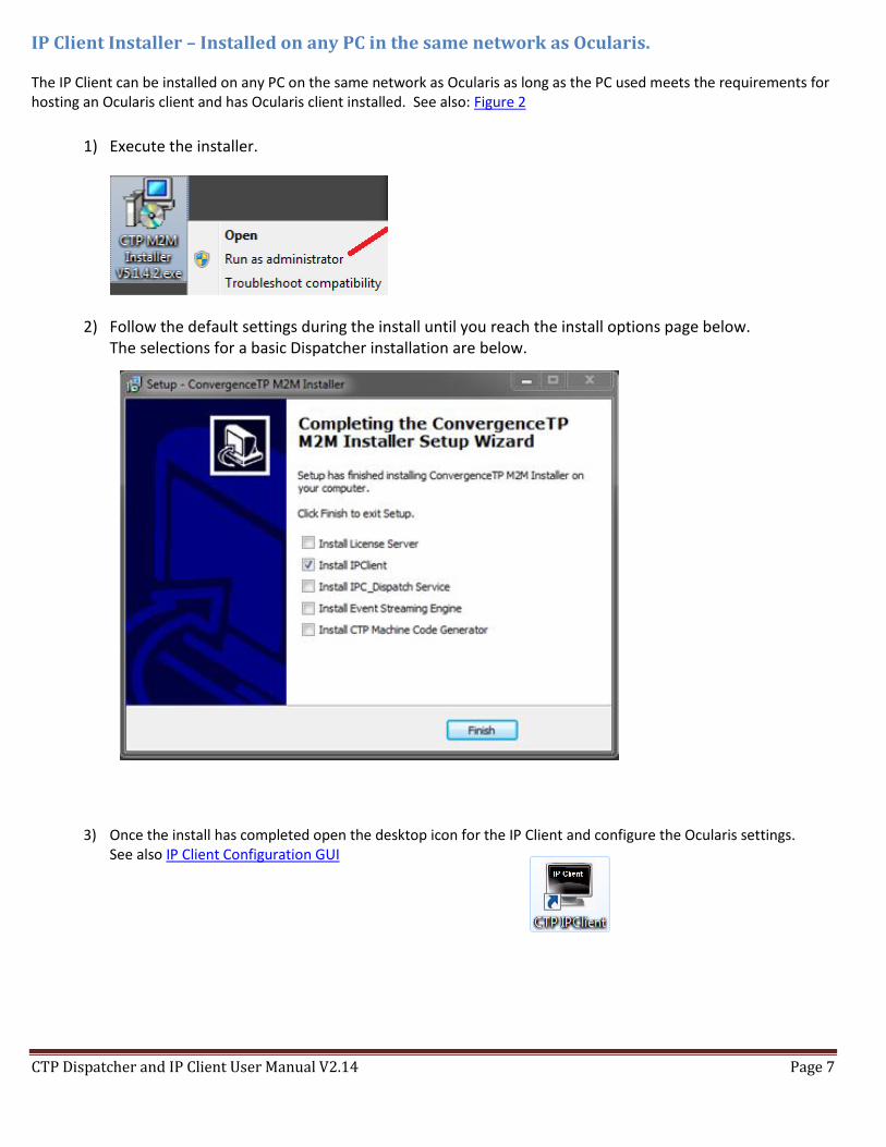
IP Client Installer – Installed on any PC in the same network as Ocularis. The IP Client can be installed on any PC on the same network as Ocularis as long as the PC used meets the requirements for hosting an Ocularis client and has Ocularis client installed. See also: Figure 2
1) Execute the installer.
2) Follow the default settings during the install until you reach the install options page below. The selections for a basic Dispatcher installation are below.
3) Once the install has completed open the desktop icon for the IP Client and configure the Ocularis settings. See also IP Client Configuration GUI
CTP Dispatcher and IP Client User Manual V2.14 Page 8
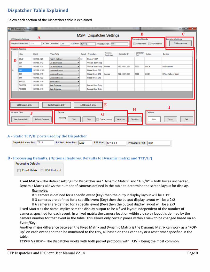
Dispatcher Table Explained Below each section of the Dispatcher table is explained.
A – Static TCP/IP ports used by the Dispatcher
B - Processing Defaults. (Optional features. Defaults to Dynamic matrix and TCP/IP) Fixed Matrix - The default settings for Dispatcher are “Dynamic Matrix” and “TCP/IP” = both boxes unchecked. Dynamic Matrix allows the number of cameras defined in the table to determine the screen layout for display. Examples: If 1 camera is defined for a specific event (Key) then the output display layout will be a 1x1
If 3 cameras are defined for a specific event (Key) then the output display layout will be a 2x2 If 6 cameras are defined for a specific event (Key) then the output display layout will be a 2x3
Fixed Matrix as the name implies sets the display output to be a fixed layout independent of the number of cameras specified for each event. In a fixed matrix the camera location within a display layout is defined by the camera number for that event in the table. This allows only certain panes within a view to be changed based on an Event/Key. Another major difference between the Fixed Matrix and Dynamic Matrix is the Dynamic Matrix can work as a “POP-up” on each event and then be minimized to the tray, all based on the Event Key or a reset timer specified in the table. TCP/IP Vs UDP – The Dispatcher works with both packet protocols with TCP/IP being the most common.
CTP Dispatcher and IP Client User Manual V2.14 Page 9
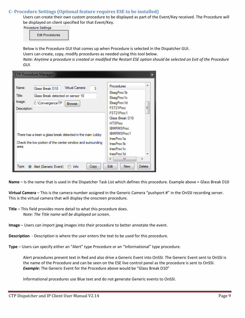
C- Procedure Settings (Optional feature requires ESE to be installed) Users can create their own custom procedure to be displayed as part of the Event/Key received. The Procedure will be displayed on client specified for that Event/Key.
Below is the Procedure GUI that comes up when Procedure is selected in the Dispatcher GUI. Users can create, copy, modify procedures as needed using this tool below. Note: Anytime a procedure is created or modified the Restart ESE option should be selected on Exit of the Procedure GUI.
Name – Is the name that is used in the Dispatcher Task List which defines this procedure. Example above = Glass Break D10 Virtual Camera – This is the camera number assigned in the Generic Camera “pushport #” in the OnSSI recording server. This is the virtual camera that will display the onscreen procedure. Title – This field provides more detail to what this procedure does.
Note: The Title name will be displayed on screen. Image – Users can import jpeg images into their procedure to better annotate the event. Description - Description is where the user enters the text to be used for this procedure. Type – Users can specify either an “Alert” type Procedure or an “Informational” type procedure.
Alert procedures present text in Red and also drive a Generic Event into OnSSI. The Generic Event sent to OnSSI is the name of the Procedure and can be seen on the ESE live control panel as the procedure is sent to OnSSI. Example: The Generic Event for the Procedure above would be “Glass Break D10” Informational procedures use Blue text and do not generate Generic events to OnSSI.
CTP Dispatcher and IP Client User Manual V2.14 Page 10
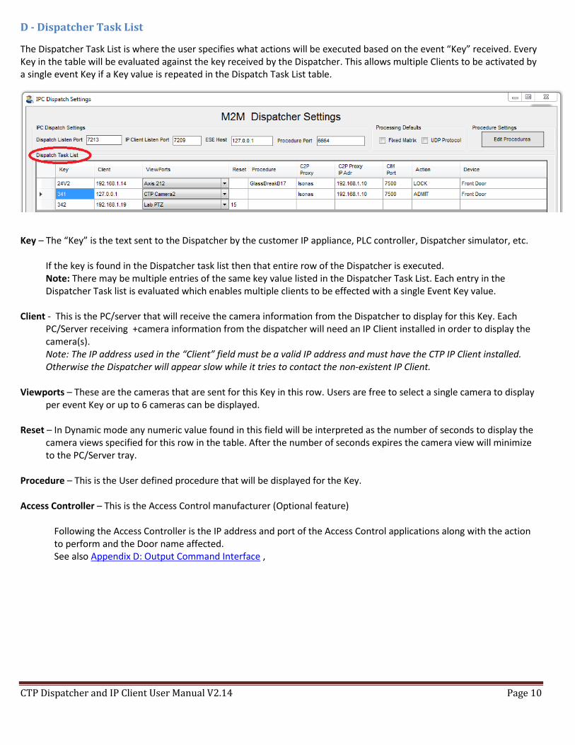
D - Dispatcher Task List
The Dispatcher Task List is where the user specifies what actions will be executed based on the event “Key” received. Every Key in the table will be evaluated against the key received by the Dispatcher. This allows multiple Clients to be activated by a single event Key if a Key value is repeated in the Dispatch Task List table.
Key – The “Key” is the text sent to the Dispatcher by the customer IP appliance, PLC controller, Dispatcher simulator, etc.
If the key is found in the Dispatcher task list then that entire row of the Dispatcher is executed. Note: There may be multiple entries of the same key value listed in the Dispatcher Task List. Each entry in the Dispatcher Task list is evaluated which enables multiple clients to be effected with a single Event Key value.
Client - This is the PC/server that will receive the camera information from the Dispatcher to display for this Key. Each
PC/Server receiving +camera information from the dispatcher will need an IP Client installed in order to display the camera(s).
Note: The IP address used in the “Client” field must be a valid IP address and must have the CTP IP Client installed. Otherwise the Dispatcher will appear slow while it tries to contact the non-existent IP Client.
Viewports – These are the cameras that are sent for this Key in this row. Users are free to select a single camera to display
per event Key or up to 6 cameras can be displayed. Reset – In Dynamic mode any numeric value found in this field will be interpreted as the number of seconds to display the
camera views specified for this row in the table. After the number of seconds expires the camera view will minimize to the PC/Server tray.
Procedure – This is the User defined procedure that will be displayed for the Key. Access Controller – This is the Access Control manufacturer (Optional feature)
Following the Access Controller is the IP address and port of the Access Control applications along with the action to perform and the Door name affected. See also Appendix D: Output Command Interface ,
CTP Dispatcher and IP Client User Manual V2.14 Page 11
E – Dispatcher Task List Entry and Editing Tools
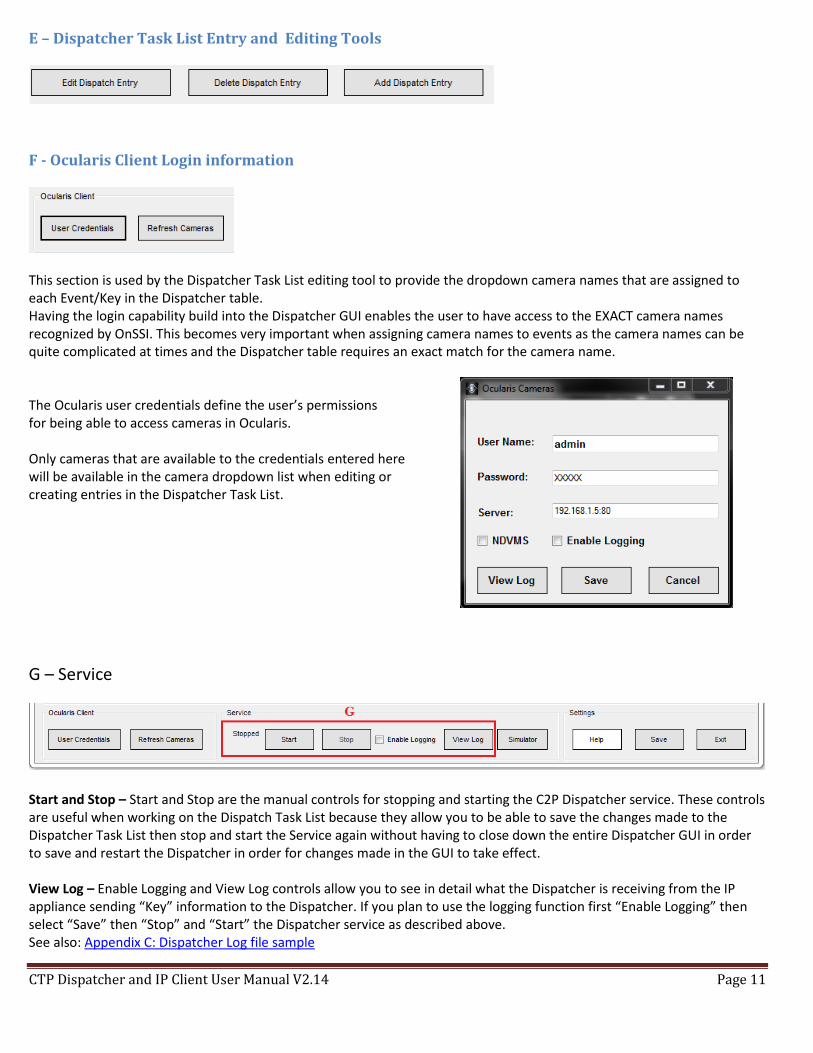
F - Ocularis Client Login information
This section is used by the Dispatcher Task List editing tool to provide the dropdown camera names that are assigned to each Event/Key in the Dispatcher table. Having the login capability build into the Dispatcher GUI enables the user to have access to the EXACT camera names recognized by OnSSI. This becomes very important when assigning camera names to events as the camera names can be quite complicated at times and the Dispatcher table requires an exact match for the camera name. The Ocularis user credentials define the user’s permissions for being able to access cameras in Ocularis. Only cameras that are available to the credentials entered here will be available in the camera dropdown list when editing or creating entries in the Dispatcher Task List.
G – Service
Start and Stop – Start and Stop are the manual controls for stopping and starting the C2P Dispatcher service. These controls are useful when working on the Dispatch Task List because they allow you to be able to save the changes made to the Dispatcher Task List then stop and start the Service again without having to close down the entire Dispatcher GUI in order to save and restart the Dispatcher in order for changes made in the GUI to take effect. View Log – Enable Logging and View Log controls allow you to see in detail what the Dispatcher is receiving from the IP appliance sending “Key” information to the Dispatcher. If you plan to use the logging function first “Enable Logging” then select “Save” then “Stop” and “Start” the Dispatcher service as described above. See also: Appendix C: Dispatcher Log file sample
CTP Dispatcher and IP Client User Manual V2.14 Page 12
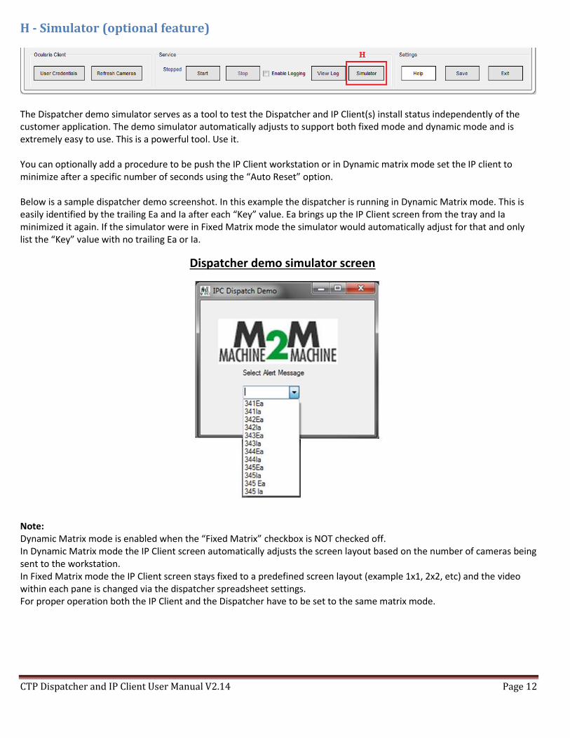
H - Simulator (optional feature)
The Dispatcher demo simulator serves as a tool to test the Dispatcher and IP Client(s) install status independently of the customer application. The demo simulator automatically adjusts to support both fixed mode and dynamic mode and is extremely easy to use. This is a powerful tool. Use it. You can optionally add a procedure to be push the IP Client workstation or in Dynamic matrix mode set the IP client to minimize after a specific number of seconds using the “Auto Reset” option. Below is a sample dispatcher demo screenshot. In this example the dispatcher is running in Dynamic Matrix mode. This is easily identified by the trailing Ea and Ia after each “Key” value. Ea brings up the IP Client screen from the tray and Ia minimized it again. If the simulator were in Fixed Matrix mode the simulator would automatically adjust for that and only list the “Key” value with no trailing Ea or Ia.
Dispatcher demo simulator screen
Note: Dynamic Matrix mode is enabled when the “Fixed Matrix” checkbox is NOT checked off. In Dynamic Matrix mode the IP Client screen automatically adjusts the screen layout based on the number of cameras being sent to the workstation. In Fixed Matrix mode the IP Client screen stays fixed to a predefined screen layout (example 1x1, 2x2, etc) and the video within each pane is changed via the dispatcher spreadsheet settings. For proper operation both the IP Client and the Dispatcher have to be set to the same matrix mode.
CTP Dispatcher and IP Client User Manual V2.14 Page 13
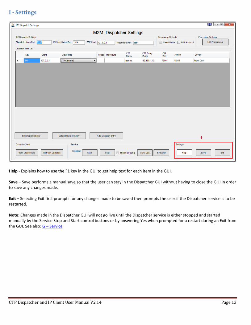
I - Settings
Help - Explains how to use the F1 key in the GUI to get help text for each item in the GUI. Save – Save performs a manual save so that the user can stay in the Dispatcher GUI without having to close the GUI in order to save any changes made. Exit – Selecting Exit first prompts for any changes made to be saved then prompts the user if the Dispatcher service is to be restarted. Note: Changes made in the Dispatcher GUI will not go live until the Dispatcher service is either stopped and started manually by the Service Stop and Start control buttons or by answering Yes when prompted for a restart during an Exit from the GUI. See also: G – Service
CTP Dispatcher and IP Client User Manual V2.14 Page 14
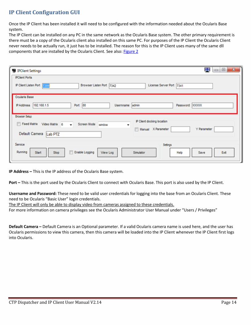
IP Client Configuration GUI Once the IP Client has been installed it will need to be configured with the information needed about the Ocularis Base system. The IP Client can be installed on any PC in the same network as the Ocularis Base system. The other primary requirement is there must be a copy of the Ocularis client also installed on this same PC. For purposes of the IP Client the Ocularis Client never needs to be actually run, it just has to be installed. The reason for this is the IP Client uses many of the same dll components that are installed by the Ocularis Client. See also: Figure 2
IP Address – This is the IP address of the Ocularis Base system. Port – This is the port used by the Ocularis Client to connect with Ocularis Base. This port is also used by the IP Client. Username and Password: These need to be valid user credentials for logging into the base from an Ocularis Client. These need to be Ocularis “Basic User” login credentials. The IP Client will only be able to display video from cameras assigned to these credentials. For more information on camera privileges see the Ocularis Administrator User Manual under “Users / Privileges” Default Camera – Default Camera is an Optional parameter. If a valid Ocularis camera name is used here, and the user has Ocularis permissions to view this camera, then this camera will be loaded into the IP Client whenever the IP Client first logs into Ocularis.
CTP Dispatcher and IP Client User Manual V2.14 Page 15
Troubleshooting As with troubleshooting any digital system, follow the data starting at the source until you find where the data is missing or wrong then debug from there. Use the many log files provided for the debug process.
Procedure Manager If any new Procedures that you create are not being displayed as expected verify that you selected “yes” when prompted to restart the ESE when you closed the Procedure Manager.
For the Dispatcher 1) Verify that the Dispatcher is configured correctly and the service is running. See Dispatcher Table Explained 2) Check the Dispatcher Log file to verify that the appliance data (the “Key”) is being received in the log file.
If not there is a good chance the data is either not being sent by the IP appliance or the data is being firewalled, etc. 3) If you do see the data coming in from the IP appliance in the Dispatcher log file but your Dispatcher is not
responding to it, then check to make sure that the data (the “Key”) is EXACTLY the same as what the Dispatcher expects the data to be in the Dispatcher Task List table.
For example 341Ea is not the same as 341EA or 341ea. (The case needs to match, as well as any spaces in the key text) Note: For Dynamic mode the Ea and Ia suffix is added by the IP appliance as a way to inform the Dispatcher to either bring up the respective IP Client or minimize it. Because both Ea and Ia affect the same line in the Dispatcher table so only the text preceding the Ea and Ia is listed in the table.
Cameras not showing up in Dispatcher Dropdown If while adding or editing lines in the Dispatcher Task List you do not have cameras in the camera dropdown pick list then verify that you have correctly setup the “Ocularis Client” section. See F- Ocularis Client Login information
Dispatcher Output commands not working The Dispatcher has the ability to send commands to “other” IP appliances. This is used for things like sending Admit commands to an access control system to unlock a particular door.
1) Check that the proxy for the IP appliance in question has been installed, configured and is running. 2) Verify that the CIM option in that IP appliance has been checked off. See Appendix D: Output Command Interface 3) Check the log file for the CIM module in the C2P proxy for the appliance in question. 4) If all is good to the log file then check that the IP appliance in question is properly configured to receive commands
from an external device. (For example in Isonas check that the INRServ is properly configured) Note: A common mistake is to install the C2P Isonas Proxy on a machine that is NOT hosting the Isonas Crystal Matrix application. This is covered in the C2P Isonas User Manual.
For the IP Client 1) First make sure that the IP Client has been installed, configured and running on the PC in question. 2) Verify that an Ocularis client has been installed on the PC hosting the IP client. 3) Verify with the IP Client Log file that the Dispatcher is actually sending the IP client in question the command to
bring up or minimize the IP client’s screen. (if not check that port 7209 is not being firewalled/blocked on the machine hosting the IP client in question)
4) Verify with the Ocularis Client that the Ocularis IP address:port and “Username” and “Password” being used in the IP Client GUI also work in the Ocularis client on the PC in question. (this is usually the problem = check this)
5) Double check that the IP address for the IP Client in question matches exactly with the Line in the Dispatcher table that you are debugging.
CTP Dispatcher and IP Client User Manual V2.14 Page 16
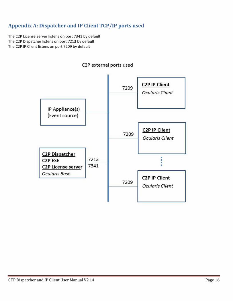
Appendix A: Dispatcher and IP Client TCP/IP ports used The C2P License Server listens on port 7341 by default The C2P Dispatcher listens on port 7213 by default The C2P IP Client listens on port 7209 by default

CTP Dispatcher and IP Client User Manual V2.14 Page 17
Appendix B: Dispatcher flow diagram using the Dispatcher simulator In this example the simulator was used as the data (“Key”) source.
1) The process starts when the “Key” is selected in the Dispatcher simulator. 2) The Key is sent to the Dispatcher service where it is then used to search the Dispatcher Task List. 3) If the Key is found in the Dispatcher Task List, then that line in the dispatcher table is executed.
Note: There can be multiple lines in the Dispatcher Task List for the same Key. This allows a single Key to execute multiple events, like sending cameras to more than one IP Client for example.
CTP Dispatcher and IP Client User Manual V2.14 Page 18
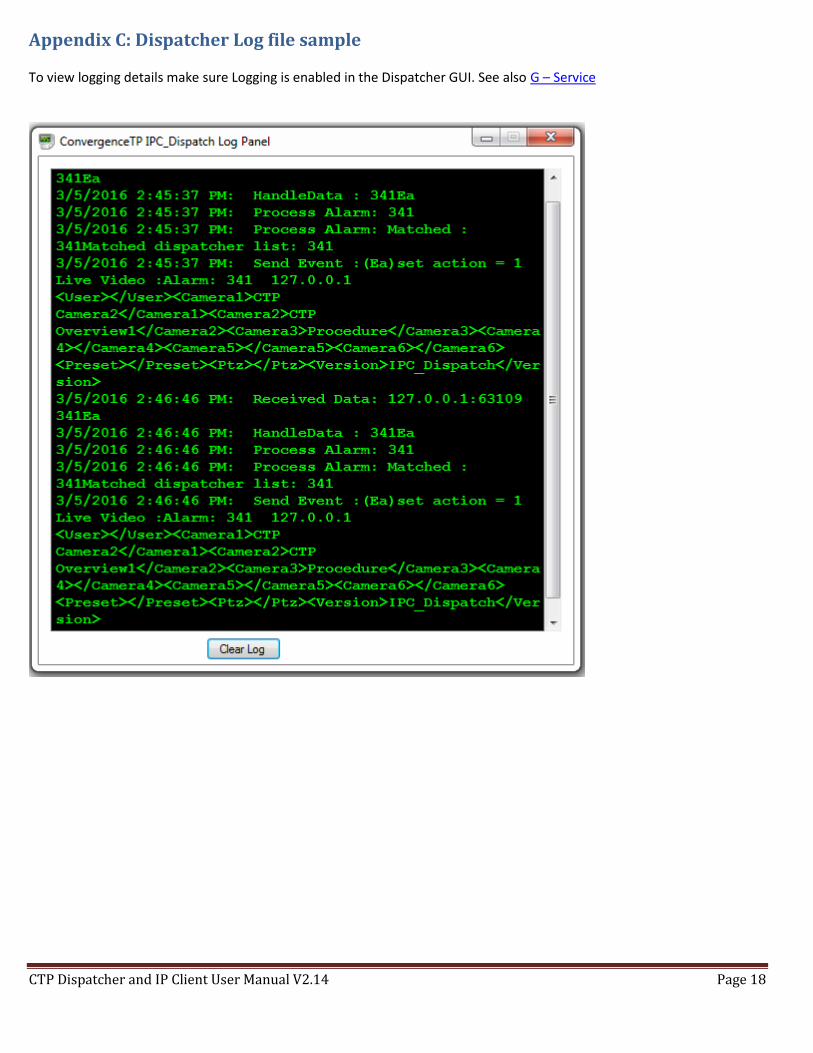
Appendix C: Dispatcher Log file sample To view logging details make sure Logging is enabled in the Dispatcher GUI. See also G – Service
CTP Dispatcher and IP Client User Manual V2.14 Page 19
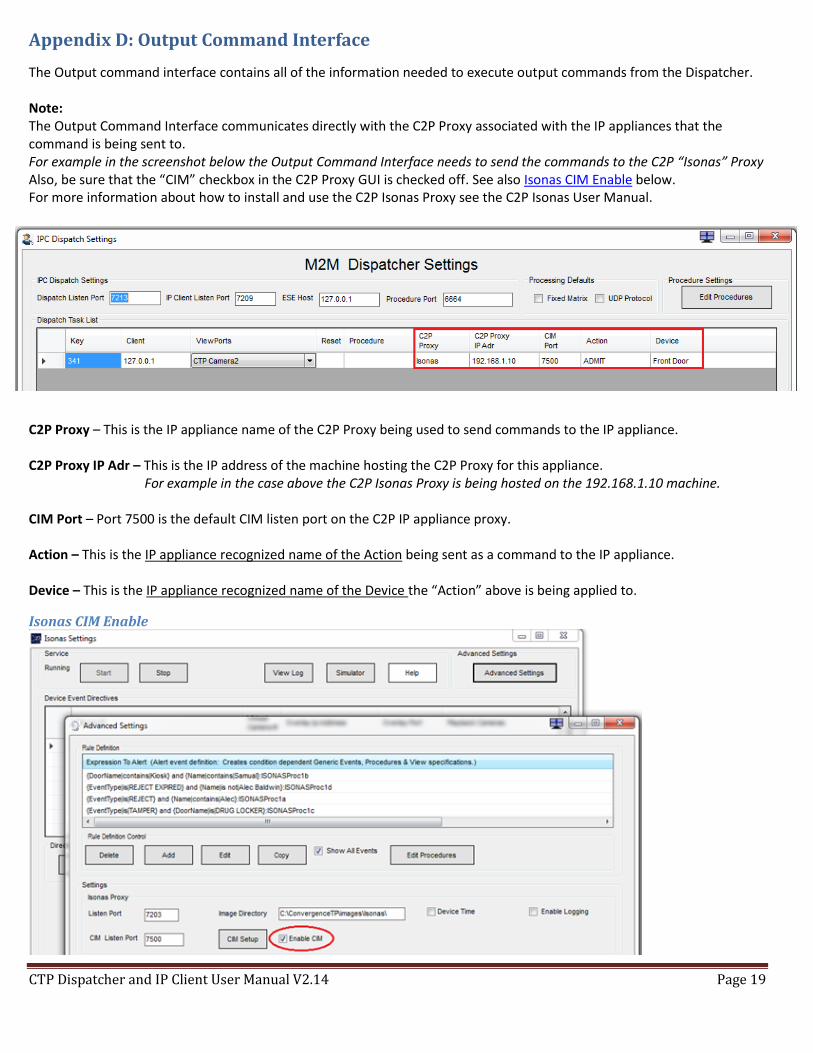
Appendix D: Output Command Interface
The Output command interface contains all of the information needed to execute output commands from the Dispatcher. Note: The Output Command Interface communicates directly with the C2P Proxy associated with the IP appliances that the command is being sent to. For example in the screenshot below the Output Command Interface needs to send the commands to the C2P “Isonas” Proxy Also, be sure that the “CIM” checkbox in the C2P Proxy GUI is checked off. See also Isonas CIM Enable below. For more information about how to install and use the C2P Isonas Proxy see the C2P Isonas User Manual. C2P Proxy – This is the IP appliance name of the C2P Proxy being used to send commands to the IP appliance. C2P Proxy IP Adr – This is the IP address of the machine hosting the C2P Proxy for this appliance.
For example in the case above the C2P Isonas Proxy is being hosted on the 192.168.1.10 machine. CIM Port – Port 7500 is the default CIM listen port on the C2P IP appliance proxy. Action – This is the IP appliance recognized name of the Action being sent as a command to the IP appliance. Device – This is the IP appliance recognized name of the Device the “Action” above is being applied to.
Isonas CIM Enable
CTP Dispatcher and IP Client User Manual V2.14 Page 20
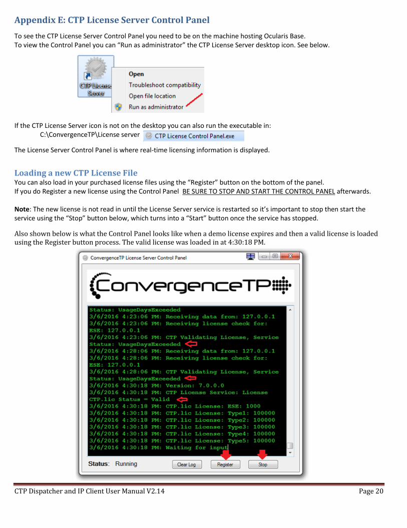
Appendix E: CTP License Server Control Panel
To see the CTP License Server Control Panel you need to be on the machine hosting Ocularis Base. To view the Control Panel you can “Run as administrator” the CTP License Server desktop icon. See below. If the CTP License Server icon is not on the desktop you can also run the executable in:
C:\ConvergenceTP\License server
The License Server Control Panel is where real-time licensing information is displayed.
Loading a new CTP License File You can also load in your purchased license files using the “Register” button on the bottom of the panel. If you do Register a new license using the Control Panel BE SURE TO STOP AND START THE CONTROL PANEL afterwards. Note: The new license is not read in until the License Server service is restarted so it’s important to stop then start the service using the “Stop” button below, which turns into a “Start” button once the service has stopped.
Also shown below is what the Control Panel looks like when a demo license expires and then a valid license is loaded using the Register button process. The valid license was loaded in at 4:30:18 PM.
CTP Dispatcher and IP Client User Manual V2.14 Page 21
Contact Information
ConvergenceTP
PO Box 3713
Danbury, CT 06813
Website www.c2p.com
Sales Support [email protected] 800.252.6840 x1
Technical Support [email protected] 800.252.6840 x2


![Seratio Blockchain whitepaper - Values Based Impact Interventions (21 Dec 2016) [v2.14]](https://img.pdfslide.us/doc/110x75/58ed5b691a28ab90718b45cf/seratio-blockchain-whitepaper-values-based-impact-interventions-21-dec-2016.jpg)