Embed Size (px)
Citation preview

I
ED-114 124,1
AUTHORTITLE (
rNSTITUTIONPEROR2 NOPUB DATENOTE
DOCUMENT RESUME
IR 002,761
Larson, D. F.; Terry, C..Advanced Simulation in Undergraduate Pilot Training:Systems Integration. Final Report (February1972-March 19:75)., 1
Aii Force Human Resources Lab.,Brooks AFB, Texas,AFHEL-TP-75-59(7)Oct 7569p.
EDRS ,PRICE M -$0.76, -HC-$3.32 Plus postageDESCRIPTORS, . craft Pilots; Autoinstructional Programs; Computer
A sisted Instruction; -Educational Programs;Training; *Instructional Systems; Integrated
.cti+ities;Military Training; *Simulators Training.Tec'hnique's; *Undergraduate Study
IDENTIFIF.RS *Advanced Simulator.Undergraduate Pilot Trining;ASUPT; -CIG; Computer Image Gebe?at!or; ICp; ,Interface.Control DocgMent
ABSTPACTThe Advanced Si7dulator for Undergraduate Pilot
Training (ASUPT) was design to investigate the role of simulation ,
in the future Undergraduate Pilot Training (UPT) program. The problemaddressed in his report was one of integrating two unlikecoMpolientsinIto one synChronized system.These.two components were the BasicT--?7 Simulatprs and theft various'subcomponents developed by Singerunder another,.contract, and thl'Computer Ipage Generator (CIG),developed by Gdneral Electric. This integration included not only the'physical mating Of the CIG system with the basic simulator cbmputef,instructor-o"perator StationS, visual displays, and cockpits, but alsothe)CompUter sotware,integration to make the visual scene correlatewit1 the flightinstruments. and t'he real wqrld.\The selected approach.4.o.integratinlithe CIG'syst&was,one of planned organization., AnIntvface Control Document (ra) was drafted early in the#programwhiCh identified the hardware and the software interface betweeh thetwo *systems. The authors concluded, that the success of this effottwas in the organization and maintenance of the ICD and the advance-'planning for the 'integration of the computer- systems. (Author/HB)
, 4
-
*************i********************************************************Documents acquired by ERIC include many informal unpublished. $c *
* materials not available from, other sources, ERIC makes every effort ** to obtain the best copy available. Nevertheless, items of marginal *
* reproducibility are oft3, encountered and this affects the quality ** of the microfiche and' hardcOpy reptbduction4sERIC makes available ** via the ERIC Document.Reproducion ,Service 1EDRS).'EDRS is not* responsible for the quality of the original document, Reproductions ** Supplied by EDES are'the beSt that can be made fromtheloriginal. *******44***************************************************************
r' A

APHRL-TR-75-59(VII)
AIR FORCEro
s.A
OLi-jr
EUS DEPNIMENT OF HEALTH,.
THIS DOCUMENT HAS SEEN REPRO
EDUCATION WELPARENATIONAL INSTITUTE OP
EDUCATION
AS, RECEIVED FROMTHE PE SON OR ORGANIZATION ORIGIN
SENT OFFICIAL NATIONAL INSTITUTE OF
ATING I POINTS DF VIEW DR OPINIONSSTATED DO NOT NECESSARILY REM 0EDUCATION POSITION OR POLIO
ADVANCED SIMULATION IN -s
UNDERGRADUATE PILOT TRAINING:' SYSTEMS INTEGRATION
SCOPE OF INTEREST NOTICE
By-
D. F. LarsonC. Terry
ERJC Facolsky has assignedthis document Cbr pr caprig
In Ole p/C19ernent, this documentis also of interest to the clewinghouses noted to the right I ncSoe
4,9 should reflect that specialp:ttnts of view
Singer-Simulation ProductsDiyisionBinghamton, New York 43902
ADVANCED SYSTEMS DIVISIONWright-Patterson Air Force Base, Ohio 45433
October 1975Final Report for Period February 1972 -r March 1975,
Approved for public release; distribution unlimited.
ABORATORY
.
AIR ORCE SYSTEMS COMMANDBRO S AIR FORCE BASE,TEXAS 78235

.
NOTICE
When US Government drawings: specifications, or other data are usedfor arty purpose other than a definitely related Governmentprocurement operation', the Government thereby incurs no'responsibility nor any obligation whatsoever, acid the fact that theGovernment may have formulated, ftirmshed, or in any way suppliedthe said drawings. specifications:or other data'is not to be regarded byimplication or otherwise. as in any manner licensing the holder or anyother person or corporation, or conqeyrsig any rights or permission tomanufacture, use, or sell any patented invention that may in any wayj:;e related thereto,
This final repqrt was submitted by Singer,Stmulation Products Division,Binghamton, New York 13902. under contract F33615-72-C-1557,project 1192. with 'Advanced 'Systems Division,, Air Force HumanResources Laboratory (AFSG). WrightPatterson Air Force Base, Ohio45433 Mr William B. Albery, Smiulstion Techniques Branch, was thecontract monitor
S,.
This report has been reyiewed and cleared for open publication and/orpublic r ease by the appiopriate Office of Information (01) inaccordan with AFR 190-17 and DoDD 5230.9. There is no objectionto unli ted distribution of this report to the public at large. or by,DDC t the lidtional Technical Iriformation.Service (NTIS).
/This technical report has'been reviewed and is approved. ',"
GORDON A. ECKSTRND, DirectorA vanced Systems Division
i
Approved for publication.
HAROLD E. FISCHER, Colonel, USAF
,
'I
.
.
1
.
..,
Commander.---/
r.
,r
Unclassified .SECURITY CLASSIFICATION OF THIS PAGE (When Data Entered)
REPORT DOCUMENTATION PAGE . ' READ INSTRUCTIONSBEFORE COMPLETING FORM
i REPORT NUMBER 12 GOVT ACCESSION NO1AFFIRL-TR-75-59(V11)
1.3 RECIPIENT'S CATALOG NUMBER
4 TITLE (ant} Subtitle),
ADVANCED SIMULATION IN.
UND RGRADUATE PILOT TRAINING:SY EMS INTEGRATION, '
5 TYPE OF REPORT 6 PERIOD COVERED
Final .,
- February 1972 - March 1975
6 PERFORMING ORG REPORT NUMBER
ASUPT-82
7AUTHOR(s).
a rD: F. LarsonC. Terry . .
i
8 CONTRACT OR GRANT NUMBER(s)
: -:F3361.5 -72-C-1557
.9 PERFORMING ORGANIZATION NAME AND ADDRESS
.Singer-Simulation Products II ision (SPD)Binghamton, New York 13902
10 PROGRAM ELEMENT PROJECT TASKAREA 6 WORK UNIT NUMBERS
63102F11920301,
I1 CONTROLLING OFFICE NAME AND ADDRESS
Hq Air Force Human Resources Laboratory (AFSC)-Brooks Air Force Base, Texas 78235
12 REPORT. DATE a
Octo 1975October13 NUMBER OF PAGES
66 I
14 MONITORING AGENCY NAME 6 ADDRESS(If different from Conttolling Office)
Advanced Systems DivisionAir Force Human Resources Laboratory -
Wright-Patterson AFB, Ohio 45433 1
15 SECURITY CLASS (of this report)
Unclassified .
15a DECLASSIE FIcAmioN DOWNGRADINGSCHEDUL
1.
16 DISTRIBUTION STATEMENT (of this Report)
-Approved for public release; distribution unlimited. s ..
.
..,
17 DISTRIBUTION ST ATEMENT,(of th abstract entered in Block 20, if different from Report)
. .
.,.
18 SUPPLEMENTARY NOTES
f
t9 KEY WORDS (Continuo on re vers side if necessary and identify by block number)
visual interface record/playback 1attitude control 4 timing synchronizationspins -'aground control a
- . .
20 ABSTRACT (Continue on revers side if nocessary and identify by block number)
Problems and solutions during integration of the ASUPT basic simulator with the computer image generation(tIG) visual system are described. Problems such as spin, stall, attitude control, and timing, synGfironization areaddressed along with the methods and ttchniqtes employed to upgrade the basic simulator dynarniL.s to meet theresolutipn and response, fidelity required fix smooth, responsive visual imagery.
.' 4 .
DD , JAN 73 1473 EDITION OF 1 NOV 65 IS OBSOLETE UnclassifiedSECURITY CLASSIFICATION OF THIS PAGE (When Data Entered)
/.
PROBLEM
SUMMARY'
The Advanced Simulator for Undergraduate Pilot Training (ASUPT)is a research device designed for'invesigating the role of simulationin the future Undergraduate Pilot Training (UPT) program:. For ASUPT
to be effective in training,relearch, it must faithfully simulate allaspectsof flight. ;This includes not only the extra-cockpit visualcues, but also the motion and farces exerted on the pilot by thesimulator, and allAof the sights and sounds to which he is accustomed.This report describes the integration of these sights, Sounds, andmotions into.a coordinated, composite system - ASUPT..
The problem addressed this report is one of integrating twounlike components into one synthronized system. These two componentsare the Basic T-37 Simulators and their various subcomponents developedby Singer under another cont ct and the Computer Image Generator, orCIG, developed by General Ele tric.. This integration included not onlythe physical mating of the CIG stem with the.basic simulator computer,instructor-operator stations, yi al displays, and cockpits, but also '
the computer software integration t make the visual scene correlateWith the flight instruments and the real world. The problem representedthe first of its kind in that it was the firscfull digital visualsystem to be integrated with a state-of-the-art, high fidelity flightsimulator.
1
. APPRQACH
The selected approach to integrating the Basic Simulators and theCIG systems was one of planned organization. An Interface ControlDocument ICD was drafted early in the program which identified the .hardward and software interface between the two systems.
and
goal of
the ICD was for each responsible,contractor to identify and quantify.,each interface parameter well iii advance of the actual integration.Various working meetings were held among ,the ContraCtors and the Air
Force aneplans for installation,:cabling, computerntegration, andtesting were established and agreed upon. After the computers wereupdated and integrated, the major problem then was one of changing theflight model in order to correct for deficiencies not detectable withouta visual system.
RESULTS
The integration was begun,in early October i974 with the mating of
the Basic Simulators and CIG general purpose computers. After this was
CJ
0
1
0
acComplishe , the test guide was trial run through Novlber 1974.Formal tes ng Of the interface began in December 1974 and the fullyintegrated/ASUPT w s accepted by'the Air Force 17 Jan 75.
CONCLUSIO'S
effort represe ts the first of its kind In simulatiOn; themating f a fully digital visual, system with an advanced flightsimula o The success of this effort lies in the organization and main-tenan e of .n Interface amtrol Document and the advance\plaNlini forthe ntegration of thescompUter systems.
s._
4'

T
PREFACE
This report is the 7th of seven volumes describing the Advanced'Simulation in Undergraduate Piles Training (ASUPT) system deyolopmentprogram. The seven volumes of A RL-TR-75-59 are as follows:
I
Volume I: AdvaiTEZZ Simulation in Undergraduate Pilot Training:An Overview
VPlume II: Advanced Simulation in Undergraduate Pilot,Training:
Mode- System Development .
Volume III: Advanied Simulation in.Undergraduate Pilot Training:.G-Seat Development
Volume IV: Advanced Simulation_in Undergraduate Pilot Training:
Automatic Instructional System41.
Volume V: 'Advanced Simulation in Undergraduate Pilot Training:Computer Image Generation
lume'VI: Advanced Simulation in Undergraduate Pilot TrainitIg4
Visual Display Development
Volume VII: Advanced Simulation in Undergraduate Pilot Training:Systems Integration
This project derived from a DOD Directive to the three Servicesrequesting programs of advanced development in the area of trainingeducation. The purpose was to insure that military training and education
-make the7fullest,use of recent innovations andtechnologicalsadvances.In October 1967, a joint Air Training Command/Air Force Human ResodicesLaboratory effort culminated in a recommendation to establish an advancedsimulation system at an undergraduate pilot training base. Hardwaredevelopment of the ASUPT began in 1971"and the system was released forresearch in Jan 75.
All members of the. ASUPT Program Office and participating organizationswho worked on the program contributed to the final system. In addition'
to the listed contract monitors,they include Don Gum, ASUPT ProgramManager, James Basinger, CIG Project Engineer, Israel Guterman, BasicSimulators Project Engineer, William Albery, Systems Integration PrpjectEngineer, Patricia Knoop, Advanced Training Systbms Project Engineer,Kenneth Block, Program Controller, and Virginia Lewis, Secretary, all ofthe Advanced Systems Division, Air Force Human Resources Laboratory,Wright-Patterson AFB OH; Warren Richeson, Capt Frank Bell III, Maj RayFuller, Capt John Fuller, Capt Dennis Way, Capt Steve Rust, Capt MikeCytus, and Mr. Glenn York, all from the Flying Training Division, AirForce. Human Resources Laboratory, Williams AFB AZ.
7 4
2a
)-
TABLE OF CON TENTS
Introduction
Optimization
Visual Interface'ModulesSimulator/Cn Interface DataCIG/SiMulator SS=nchronization .
Transport DelayLime CompensationC-ue Correction
"Attitude Control.Groand ControlSpiFo mation Flfght,
Record/Playback (RAP)
Summary
I
Page
5
, 7
88
14
161721
2222
, 253341
43
45
Refetences 46
Appendix A - ASUPT Technical Fact Sheet 47
83
4
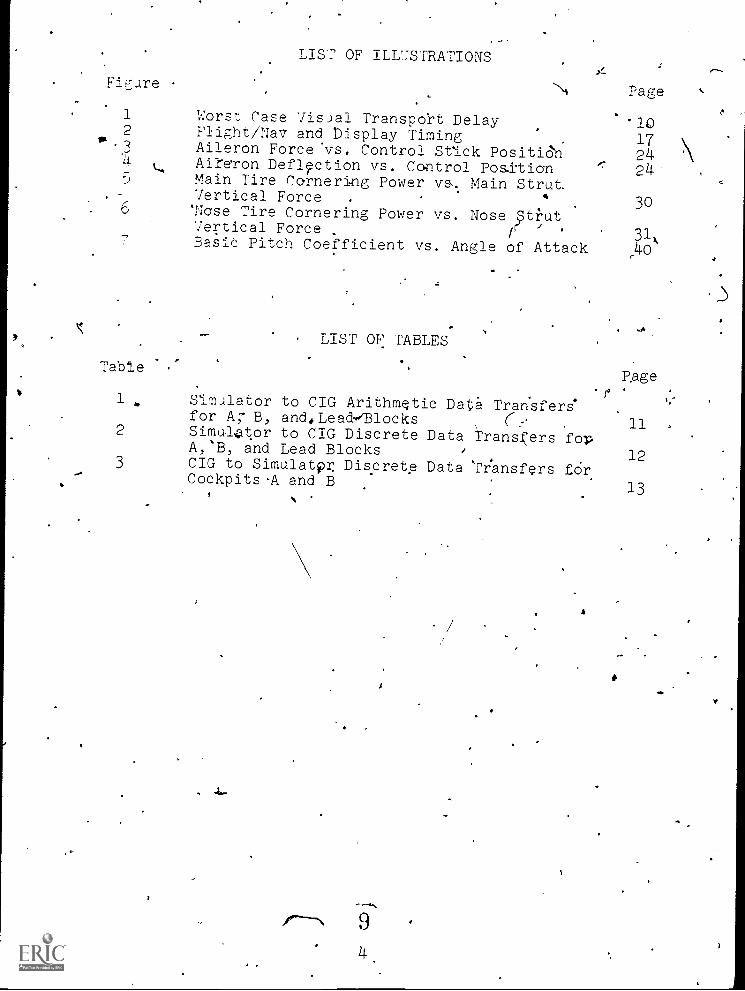
LIST OF ILLUSTRATIONS
Figure
1
2vs.
34
LA5
. -
. 6
Worst Case Visjal Transport DelayFIight/Na7 and bisplay TimingAileron Forcevs. Control Stick Positio'nAinon Def4ction vs. Control PositionMain Tire Cornering Power vs,. Main Strut.7ertical Force .
4
'Nose Tire Cornering Power vs. Nose St2ut7ertical Force
/
.
BasiO Pitch Coefficient vs. Angle of Attack
'.
Page
'10172424'
30
31k
..40
LIST OF TABLES
TableP.age.
1. Simulator to CIG Arithmetic Data Tran'sfers.for AT B, and,Lead-,Blocks
112 Simultor to CIG Discrete Data Transfers fopA,B, and Lead Blocks 123 CIG to Simulatp Discrete Data 'Transfers fOrCockpits -A and B
13
pm 94

INTRODUCTION
The ASUPT simulator/CIG integration effort is the firstof its kind in the respect that it is the first full digitalvisual system (,terrain and T-37 model) to be integrated withan operational flight trainer. This report describes theproblems and solutions associated with -thee accomplishment of
this task. A.s o9e may expedt, some problems are common with
'model visual systems such as, ground reactions. Accordingly,other problems are unique to a digital system, such as timing
and iteration rates:. -
The ASUPT facility (located at Williams AFB, Arizona).consists of three primary systems (see Appendix A for a de-
scription of the ASUPT system):
(1) Simulators
(2) Visual System Displays
(3)
The simulators and visual system displays were procuredby the Air Force'under contract to Singer-SPD in 1971. De-
livery of the systems was made to WAFB, in the fall of1973,with final acceptance by AFHRL in February of 1974.
The computer image generator (CIG) system was procuredby th.e Air Force from the General Electric Company in 1972,and was delivered and accepted at WAFB in September 1974.
In 1971; Singer-SPD contilacted to integrate th4 simulator
and .CIG systems. Actual.integration began with the ptocure-.ment of the CIG and was regulated and,controlled by an SPD-generated Interface Conti-.01DoCument (ASUPT-59)2 -monitoted by
AFHRL. Computer integration began in October of 174 and wasfollowed by the. ASUPT/CIG integration which was completed17 January 1975,
Computer Image Generator (CIG)
Prior to the final integration phase,:the following in--
tegration-related events were completed:
(1) Simulator visual interface subroutine,developmentand stand-alone debug. .
(2) Integration of the visual interface programswith the simulator real -time load.
(3) Physical mounting, cabling, 'and alignment of'CRT tubes, electronics, instructor station monitors, ?tc.
(4) Testing andverification of the simulator andCG,systems in an independent but concurrent mode. .
1 t)
.
I
\ A
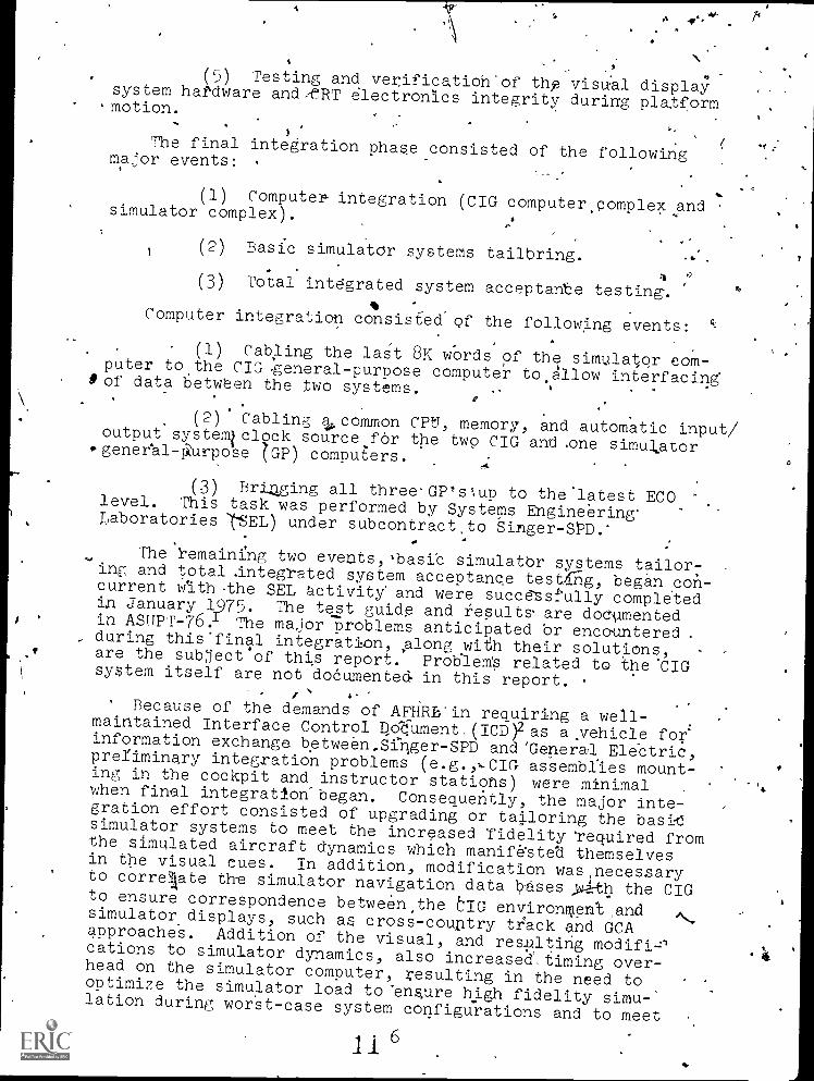
(5) Testing and verification'of thfa visual displaysystem haPdware andteRT electronics integrity during platform.motion.
The final integration phase consisted of the followingmajor events: .
(1) Compute/. integration (CIG computer,complexandsimulator complex).
(2) Basic simulatOr systems tailbring.
1(3) Total integrated system acceptante testing.% -
Computer integration consisted of the following events:.,
(1) Cabling the laSt 8K words of the simulator com-puter to the CIG general- purpose computer to.klow interfacingS of data between the two systems. , ,
0
(2) Cabling 1,,common Cipti, memory, and automatic input/output systemiclock source for the two CIG andone simulator..geneeal-1-:Orpose ZGP) computers.
(3) Bri4ging all three-GP's%up to the latest ECOlevel. This task was performed by Systems Engineering.Laboratories (-SEL) under subcontractto Singer-SPD.'
The remaining two evectts,.basib simulatbr systems tailor-.ing and total .integTated system acceptance test1rig, began ,con-current Ath.the SEL activity' and were succe'ssf'ully completedin January 1975. The test guide and results are doCumentedin ASTIPT -76. The major problems anticipated 'or encountered
., during thisfinal integration, ,along wi-eh their solutions,are the subject` of this report. ProVle* related to theCIGsystem itself are not doeumented in this report.
Because of the demands of AFHRL'in requiring a well-maintained Interface Control po'dument (ICD)2 as ayehicle for'information exchange between,Sfter-SPD and'Generaa Ele'ctric,preliminary integration problems (e.g.,,-CIG assemblies mount-ing in the cockpit and instructor statiohs) were minimalwhen final integration-began.Consequently, the major inte-gration effort consisted of upgrading or tailoring the basil
simulator systems to meet the increased fidelity 'required fromthe simulated aircraft dynamics which manif&steli themselvesin the visual cues. In addition, modification was necessaryto correaate th-e simulator navigation data bases >rath the CIGto ensure correspondence between the bIG environTen't andsimulator displays, such as cross-couitry track and GCAapproache's. Addition of the visual, and resultingcations to simulator dynamics, also increased. over-head on the simulator computer, resulting in the need tooptimize the simulator load to 'ens,ure high fidelity simu-lation during worst -case system configurations and to meet
6
4

1
! _, , -
the backgrour4 (core and time) reqirements of.tn 'state-
ment of work (SOW),
seen.
OPTIMIZATION -
...
Although the basic simulator dynamic1 were designed from--the beginning to meet r olution requirements for a srpoqt(1-1
irvisual display, certain probleriis.could only he'anticipa-Ged .
-and planned for; their sblution:had to be addressed during .
the coUrse of actual, iritegration when the problem could be
In order to meet' SOW specifications for spare cc4e*andandto accommodate the'increased core and time de2
manded by inclusion of the visual interface modules and up-grading of the simulator dynamics, existing modules required-
optimization; Without optiMization, successful integrationwas not possible. 'The 'simulator was capable bfhandling anaverage configuration of both cockpits active with motion,'G-seat, and visual'; however, placing one cockpit in a-for-mation flying mode overloaded every other frame. ale ex .
ec,utive, although designed to distribute one fraWs excesinto another's spare,, could not catch up, Simulation, fidelity,degraded, operator software-driven displays failed, and
.
training was impossible .until one cockpit was placed bff-line.Likewise, it was deteilmined that two modules, one computing'formation flying irtertial axis separation and the other com-puting aircraft position, would have to be increased from a .
7.5/secOnd to a 15/sebondit'eration rate to eliminate object-ionablegotranSlational stepping-and resulting pilot controlproblems during formation flying. Examination of tieing statistics 'showed that-approximately 10 to 15 millisec9nds pe'r
frame were needeti to fit the load in the 66.67-millisecond '
,frame and meet spare time-requirement of 20percent.' 'Initialoptimization efforts began immediately upon final in'te&atibn,and_continued throughout the integratioD phase. :These effortsconsisted primarily of the followingf .
(1) Optimization 'of assembler 'and Fortran techniques,
e:g., replacing sTUare and'divide functions with multiply.
functions.
(2) Reducing the formation flying' wake and down-
wash model to comptte'dynamic effects on two lag aircraftwing points rather than four.
(3 Modification of the "linear function inter-polator (LFI) jump list to allow slow computed functiOns tobe called at rates of 7.5/second rather than 15/second.
(4) Implementing faster methods for calling oer-ating system services.
-(5) Optimizing instrument drive 1D-r(51:srams to
inate unnecessary, Fortran conversion calls.
7. I9

I
o
. ,
.. (64. built=.in;but virtually unusedtest funCtionshfrom G-seat, and navigation sys-
tem mtdule.S. .7,.1
,. - . ` ...
.'(7) unnecegsary interrupts..,.
.t..(8) RestrAturing the module jump list to proviAe, .
....
- 'f 1pad.distribuion.and Symmetry-
. . .: 0
. Significant results were achieired; resulting in 'a core.increase of approximately 8K- words. and time of apkokimately12 milliseconds/frame. Tiv success of this ffort...resl.lited .
in .the elimination of rpmeras, pfoblems manifested in: ail;systems, npt just the visgal system., anti, allowed'full-con-.
, figuratiOn:use of the simialatory including thecaRabilityto pefTOrmbatch,operatilons in the .spare .frame or background,time. .. :
. 4 .0 * ' /:
. VISUAL INTERFACE.
Modules(, .. ' .
. .
Three modules were,developed.to perform 'ate fundtions. necessary to-interfac-e the basic simulator with ,the CIG,and they
,,.. 1,
11. r
.-.
. (,
O
, (1) Visual Fast subroutine
(2) Wisual,Slow subroutine'
(3)._ Vigual Logic subroutine
The ViSuai Slow subroutine is called once pet second,by,thq'slmalator executive. It computes the sines and cosinesof the angular:corrections necessary to correct the4flightsystem's flat-earth heading tomap heading. This correction'
, contains both the transportangle and the meridian conver-gence. The transport angle is employed by the simulatornavigation programs a8 well as the Visual Slow subroutine':e9 transform flight heaMing to spherical earth (true) heading.The meridian convergence correction is necessary to com-pensate for'the transverse Mercator mapping scheme, to which,the CIG environment data base is modeled.
The Visual Fast, subrbut.ine i6lexecuted.,30'times per -, second.. It rbmputeg (and' interfaces with CIG) the simulator
position arid,attituat date for cockpits A and B and the leadaircraft, when formation flying mdde. Unlike 'Logic andSim subrOutines, Fast subroutine ib note executed-by theexecutive $tit'directly,by a 30 /second interrupt handler. ThehandleinAurn is if0)ked at a 30/second rate by a clock
138
The Vi Logic subroutine is called 3.75 times persecond by the simulator executive. It performs, logical com-putations such as'vi-S1141 reset, °fly/off, crash, etc.
4

originating in the CIG special= -purpose computer that leadsthe video frame by 10 milliseconds. This lead'allows the Fastsubroutine to make the position and attitude updates beforeCIG starts its frame. The direct connection to the inter-rupt handler was necessary because the executive could notsupport a 30/seconck rate (15/second is'maximum) with a. fixed'33.33 millisecond interval as required and shown in figure.1.Extensive modification to the executive and module jump listwould have been necessary. The fixed interval was necessa/7.,,,in order to compute an accurate transport delay compensatidn''and lead prediCtion for the interfaced pcsitIon and attitudeda.a...in the Visual Fast subroutine. chile the direct methodeliminated the need for executive modification; some specialconsiderations were necessary. The Visual Fast subroutinelad to meet the restrictions,imposed upon interrupt- connectedsoftware 'elements. Specil'ically,-the Fast subroutine could"not'use common datapool temporaries.andmath library sub-routilnes since it could nterrupt other executive-connected,modules using -these eleMdnts, thereby changing their state.Consequently, all temporaries and subroutines used in theFast subrOutine were made local. The penalty for this wasa Minor increase, in core overhead cf approximately 50 words:
Simulator/CIG Interface Data
Four blocks of fixed-point arithmetic and discrete data.are,transferred'between thesimulator and CIG computers. Oneblock isIdedicatced to cockpit A, one to cockpit B, age, to thelead aircraft, (cockpit A, B, or the AIOS emulator) when in aformation flying mode andone block to cockpit A and B miscel-laneous discretes.. This. data is ,detailed in tables 1, 2;and,-3.
Because of the Interface Control Document (ICD), .no ad-dressing, resoltAion, or definition problems were' encountered'in interfacing this data.
The method of ,transi'erring'the data between, the basic sim-ulatoAand,CIG was specified to ,be by means of shared, core.Pripplo final integration; thi-smethod was analyzed and shownt9 post a' potential problem for the .followihg reasons. Al-though the CIG computer was required to move the interfaced
00data to a local (non-shared) area in its own o e, no guaranteeor protect feature could be designed to safe a d against CIG
...read/write' access to any address in the share 8K area which-comprised-80 percent of the simulator datapool. (Minimumshared core'in the SEL 86 system is on 8K word boundaries.),
Therdfore, it was pospible for the CIG system to overwritesimulatorivariables, resulting' 4n degraded performance orundefined simulatOr system aborts and CPU halts.
/
9 1 4

1 7l
-(.
30/SECCIG INTERRUPT
15/SECANALOG INPUTS(AM
15/SECANALOG OUTPUTS
(A/0)
18/SEC
FLIGHT/NAV
30/SEC
CIG INTERFACE
30/SEC-CIG COMPUTER FRAME(STARTS 10 MS AFtERCIG INTERRUPT/4
.
__._
, .
1
1
0.
1 46.,)1 _..
I
.1
It /
. ..
)
9 1 +-1
, .
1
1
v
.
.
.
,
1
67 MS 1
33 MSI
10 MS
10
O
83 ms
\1 CONTROL POSITION CHANGE MADE JUST AFTER TRANSFER OF A/I'S TO CORE MEMORY.INFORMATION MUST WAIT FOR THE NEXT TRANSFER.
2 INFORMATION TRANSFERRED TO CORE MEMORY, READ BY FLIGHT
3 FLIGHT/NAV COMPUTES STATE CHANGES, PASSES NEW INFORMATION CIG INTERFACEPROGRAM
3A UPDATED INFORMATION AVAILABLE FOR SIMULATOR A/O'S
4 CIG INTERFACE PROGRAM COMPUTES NEW VISUAL. STATE VARIABLES AND PASSES THEM3'0 CIG COMPUTER VIA SHARED MEMORY
5 CIG SOFTWARE/HARDWARE REQUIRES 83 MS TO PROCESt UPDATED STATE VARIABLES46 RESULTS OF 1, ARE DISPLAYED BY VqUAL
TOTALDEL4Y .-183 MILLISECONDS
NOTE BEST CASE OCCURS WHEN 1 ARRIVES AT LINKAEIJUST BEFORE ANALOG INPUTSARE.TRANSFERRED TO COREMEMORY AND IS 67 MILLISECONDS SHORTER (126 MS).
Figure 1. WORST CASE VISUAL TRANSPORT DELAY
I 510
44.
s'

Table 1.
.SIMULATOR TO CIG ARITHMETIC' DATA TRANSFERS FOR A,'B,AND/4EAD BLOCKS
Arithmetic
--.
.Block 1
Resolution &
.
Parameter
Description
Entry
Units
Scaling
Accuracy
.
-6'
lat
The latitude coordinate of
Word 1
Deg
B4
7.4 x.10-9
Williams Air Force Base
touchdown point will be
subtracted from the extra-
polated Simulator A view-
ing point.latitude -
.
(A lat = 0 -33.299699).
Along
'The longitude coordinates
Word 2
Deg'
B4
,
7.4 x 10⁻⁹
of the central meridian'
,.
L(-111.00) will be
,
sub-
i-
'.
4114111
tracted from the longitude
-t
coordinate of the extra-
polated
.1---,
simulated Air-
,craft A viewing point. West
..
...
longftudesare negative
(Along = X +111.00)
..,.
,
hvp
Pilot's viewing point
).Word 3
Feet
'B22
0.002
altitude above MSL. The
.,
ed Aircraft A
centf7T gravity alti-
tude above MSL will be
A
extrapolated and, added
.
to the vertical.com-
9.1...,
ponent of the vector r'
defining the,,position'
of the viewing point
Arelative to the center
of gravity.
..
.

H rs3
Table 1.
Arithmetic
-Parameter
C 1;1
\--.c 3,1
C 2,2
C 1,3
C(3,3)
C. C
2,1
1,2
3,2
2,3
SIMULATOR
TO'CIG ARITHMETIC DATA
TRANSFERS FOR A,.$,.AWD LEAD
BLOCKS (Cont)
DpScription--,
Narix-df thedirection
cosines relating air-
craft axis system to
the
flat earth axis
system
for -Aircraft A. The
direction cosines will
include heading
cor-
rection to true head-.
ing to account for
transverse mercator
meridim convergence,.
The convergence term
will -be zero at.coor-
dinates lat =.
N33.299699, long
=.'
W1110.
Block 1
Entry
Words 4-
'12
Y.
Resolution &
Units :
Scaling'
Accuracy
nori,dim
9 x 10⁻¹⁰.
Table
SIMUATOR TO CIG DISCRETE''-DATA- TRANSFERS FOR A,
B, AND LEAD BLOCKS
A
Discrete Parameter
.Description
Block 1 Entry
1/0
The simulated aircraft
Word 13 Byte 0
state vector for Aircraft
'A is being reinitialized.
Word 13' Byte 1
experienced a "crash"
con-
dition.
Reset.
Crash
Reset/Normal
Crash NOrMal

1
ar. Table 3.
CIG TO SfMULATOR flISCRETE-DATA TRANSFERS FOR COCKPITS A AND B
.. Discrete Parameter
Description
Block 4 Entry
1/0
CIG Ready
The CIG is ready to accept up-
Word 1 Byte 0
Ready /Not
dates of simulated Aircraft A
fr
Ready
.
state vector following a simu-
,lator reset.
Terrain Collisiop
.The altitude of simulated
Aircraft A pilot viewing
point is less than the
terrain elevation.
wCIG Ready.
The CIG is ,ready to accept
updates of simulated Air-.
craft B state vector
lowing a simulator reset.
Terrain Collision
Word 1 Byte 1
Collision/
Normal'
Word 1 Byte 2
Ready/Not
Ready
The altitude of simulated
Word 1 Byte 3
Collision/
Aircraft B pilot viewing
.Normal
point Is less than the
.44
terrain elevation.

Anozher anticipated problem with i'egard.to shared corewas mehwry Iparity errors. Frequent parity errors occurredduringhe development of the basic simulator. It thereforefollowed ,that increasing demands on an 8K memory module couldresult in a prohibitive increase in parity errors and ex-e'rci'se downtime.
To prevent these problems, an alternate method,Of transfer -rip the required data was studied. In this, approa'c'h, blockeddata is exchanged 4,y means of the SEL 86 automatic input outputsystem together with device controllers, and data terminals. Theabove sysiLe-, ;,could be under program'controlrand therefore wouldhave more potential for safeguarding datapool and would decreasethe potential for,parity.errors through eliminatiOn of the ad-ditional active shared memory. While this was a desirable feature,implement'ation would have required development and debug ofhandlers in both the basic and CIG systems and increased hard -ware complexity with its potential roblems. It was thereforedecided to implement the shared-core technique despite itspotential risks. During integration every few parity errorsoccurred and no actual invaliqCIG system memory accesses Wereencountered. In general, the shaped-core approach was straight-forward, simple to implement, and. problem'free.
CIG/Simulator Synchronization
To insure that for each data transfer from the simulationcomputer, the corresponding frame of video was displayed, and toinsure accuracy for the numerical, transport delay compensationin the visual interface subroutine, frame synchronization be-tween the'simulatOr and CIG was necessary. Since,the video framerate was 30/second, the same as the basic simulator half-framerate (the basic simulator rate is 15/second), no'special syncprobAms were envisioned 'other than implementing a technique:Two ideas were studied. The firSt idea was to allow the twosystems to run on independent 30/second clock sources with thesimulation computer monitoring and adjusting for drift due todifferences in resolution atone-secon4intervals-, and the secondidea was to select one system's clock ag master with-the othersystem slaved to it. Both methods reqtared cabling to exchangethe clock signal via a interrupt. Whil4the first method wasfeasible, it required additional software 'to monitor and adjust,for drift of two independent clocks and thereby did not guaranteeaccurate frame-to-frame synchronization unless the monitorexecuted at the clodk rateopf-30/second. This monitor wouldadd significant system timliw overhead at a 30/second rate in asystem already heavily loadd1R. The second method however didensure frame-to-frame synchronization, and-the'dnterrupt structurein the SEL 86 with i,:ts programecontrol cappility lended itselfto'this technique and h,ence was the employed method. The onlysoftware modification necessary was to incorporate a three-instruction'interrupt handler to receive and gate the clock tothe simulator computer interval timer, which already served asits normal independent clock 30/second .SOUTCe. Thus, to the',

simu4.etiOnsoftwate, the synchronization activity was non-inter-ferin'and transparent: The three-instruction handler added asmall (approximately 2.5 :nicroseconds) timing overhead per inter-
.. rapt. .
The computer image generator, rather than th'e basic simu-lator, was selected as the master to relieve CIG of the burdenof systemsy,pchronization because there was available in theCIG special purpose computer a hardware generated 30/second'clockfrom 'the same timing network being Jsed to time the three riG .
system computers. This also assured a total common system clockr4solut3tm. Hardware was required to make the clock externallyavailable. A shielded coble was used flop route the signal to thesimulation computer (approximately 60 feet). To insure immediate'software handling, the-clock was connected to the highestable external interrupt (system, override) on the simulationlcom-,pater. ,
1
A pote ntialiprot)lem existed in u sing this level. Becau.ethe system gverAide is higher in priority than the peripheraldevice direct meory access transfet interrupts, its active statecould interfere, with a data transfer.sequence on a high speddevice (e.g., disc) causing-a data lost'ondition. Consultationmrith SEL-8b engineers revealed, howeveir, that this problem lould
only'occur if the interrupt was active longer than 8 micro-seconds. For this reason, no tasks or services other than satingof the interrupt'down to the lower level interval timer was e-si'gned into-the CIG interrupt handler resulting in an executiontime of approkimately 2.5 microseconds.
A
_Should interrupting the input/output structure have been aproblem, the alterative was to use a lower external level.next available leNtel however was in priority behind all other'interrupts in the system. This represented potentially exces-sive service delays witch 'an inconsistent frame interval duringperiods of high interrupt activity which is common in a multi-level task orientated operating system with foreground/back-ground capabilitye
A fallout advantage of using this level also resulted. It
was considered necessary to design into the6a4c support soft-ware a method for selecting the simulator clock or the CIG clock.This would allow independent asynchronous operation of th simu-lator shoulda maintenance problem develop in the CIG specialpurpose clock hardware; t,S'pecial software incorporated into, the
simulator executive would have been necessary tp provide theabove service. HoweveY, the system override level has a hard-ware enable/disable feature via a key operated switch on the
,SEL 86 console which in effect performed this function. Thus, '
-%-selv,ction of clock source and the capability of simulator-depend-;,1)t or independent operatidn was simply determined by the-turnof a key., without the need for additional software.
2)15

This ingenious method of System synchronization was not onlysimple but proved to'be problem-free during the course.of inte-gration.
LEANSPORT DELAY
. .
.Because of the time required by digital computers to performthe logical and mathematical tasks assigned to them, real timedigital simulation consists of the instantaneous sampling ofpilot activity ( flight control positions, switch positions,etc.), computation of the effects.of this sampled activity onthe simulator state variables, and feedback of the effects of theupdated state variables via instrument indicator light, motion,and visual displays. This cycle is repeated at even time intervalswhose length is determined by the speed of"operations in thecomputer and the size of the taskload to bet performed. The ASUPTsystem, havin6 d ldege taskload, cycles at a maximum rate of 15iterations per second. All computer input-output and flight 1dynamics programs operate at this rate, while other rates (74/second, 3.75/second, and 1/second) are employed by less timecritical programs.
An undesirable result of this'iterative scheme is that someincrement of time (referred to as transport delay time) mustpass before the simulator pilot is ,provided with feedback molt-ing from his control activities. the-transport delay tiis excessive, the pilot must learn riot only to anticipate thdynamic response of the aircraft being simulated, but to compensate for the delays involved in presenting that responsehim. The impact of transport time delay is dependent upon tocontrol response expecd by the pilot, and his ability to dgethe presentation of that response. Fox instance, transportdelays in the ASUPT latitude/longitudeIiieritial position coreputations (originally computed-at 7.5 iterations per seconds werenot a factor for any talk except formation flying, where le*accurate judgment of_transigtional rates is required. Inn' lasingthe inertial position iteration.rates to 15 per second resq'tedin vast improvements in formation flying position control,, uthad no.noticeableimpact'on other tasks such as approach arlanding marieuvers. The greatest impact of transport delay 'is inthe control of Aircraft roll position. The T-37 aircraft Has lowroll itlertia coupled with powerful aileru0 and light controlforces, resulting in roll response'whiCh is.rapid and positive.Inclusion of a visual system in the simulation provides, with itshorizon extending the full width of the pilot's field.of view,a far more precise indication of roll response and dynamicsthanis available from attitude instrumentation.
;\Under the limitations of computer time loading as Teflebted
by maximum available, iteration rates, transport time delay 'inthe ASUPT system has been minimized. Figure 1 graphically*dem-onstrates the worst case visual time delay for primary control(elevator, aileron, rudder) applications. The difference be-tween worst-case and best-case time delay is due to the fact that
16 21

the simulator pilot may make control adustments-at any time,but control positions are sampled by the simulatOr software only
at 66.67 millisecond intervals. Phe 83 milliseconds required bythe visual system software/hardware is indicative of the massiveamount of computation required to convert the simulator attitudeand positional data into a representative visual display.
Ile exact fmpact of the 126 to.193 millisecond transport de-
lay JIIke upon the ASUPT roll Controllability is unknown, asother problems are thought to exist in this area (see section on
Attitude Control). General consensus among the personnel in-volved with the ASUPT visual integration is that these ficwresshould, ideally, be reduced. Such reductions, however, willrequire faster computational equipment in order to provide fasteriteration rates in the simulation computer and to reduce the 83millisecond delay in:the CIG system.
Time Compensation
The visual interface equations employ the Taylor series forf(t +6 t) in order to, compensate the visual interface arithmeticdatafor differences betWeen the time for which they are com-puted and the time at which they will be displayed by the visual
system.
Tfae integration ,scheme used in the ASUPT flight dynamics_
equations provides results as follows (seATigure 2):
(1) Analog inputs at time (N) are used to computeacceleations at. time (N)
33 MS
CIGINTERRUPT I I I I 1 I
ANALOG INPUTSFLIGHT/NAV
A/I hit A/I A/I67 MS 67 MS a
th il ri /I-1(N) IN+1) (N+2) (N+3)
CIG INTERFACE nSUBROUTINE 11 y® fl il fl11:
O ,1,
Ilr DISPLAY 0I .
DISPLAYO:
127 MS--gpfI
I I
14 160 ms
Figure 2. FLIGHT /NAY AND DISPLAY.TIMING2 2
, 4

(2) Accelerations at (N) are integrated to give ve/-,ocities at (N+1)
(**(3) Velocities at (N+1) are integrated to give positions',at (N+2)
All of the above parameters end (as a result of the inte-gration formulas) the (N) velocities9.nd N+1) positions areavailable to CIG interface cycles labeled and Q as shown infigure 2.
4The Taylor'series is:
At 2',
At3f(t44,6 t) = f(t) +A tf'(t) + 2: "(t) + 3 f"'(t)
',If time (t) is assumed to occur at '(N+1):
A t2 -, A t3f(t 41 At) f(N+1) +A tf (N+1) + f"(N+i) + f" (N+1) .
k 3:
where ,At is, so, far, undefined.
Since f"(N+1), the acceleiationat time (N+1) and all higher-order derivatives are unknown d-uring CIG cycles and Q, onlythe first two terms may be used.
f(;t + At) = f(N+1) + Atf1(N+1)
Av. .Thp value of At can be established by reference to ,figure 2.Time (W+1) occurs 67 milliseconds after time (N), whereas the ,displays associated with time (N+1) occur 127 milliseconds and160 triiiliseconds after time (N):
At = 126'- 67 = 6o ms-
A t = 160 - 67 = 93*ms
Time (N+1) has been chosen as the extrapolation basis becauseof the availability of velocity (N+1); however, this results inthe use of'a position term which is one iteration behind thelatest position term available (N+2). The (N+2) position termsmay be used in the fpllowing manner.
Assuming:
f(N+2) = f(N +l) + 0.067±"(N+l)
where Q.067 is 'ale 15 iterationsper second quadrature interval.
23 18i
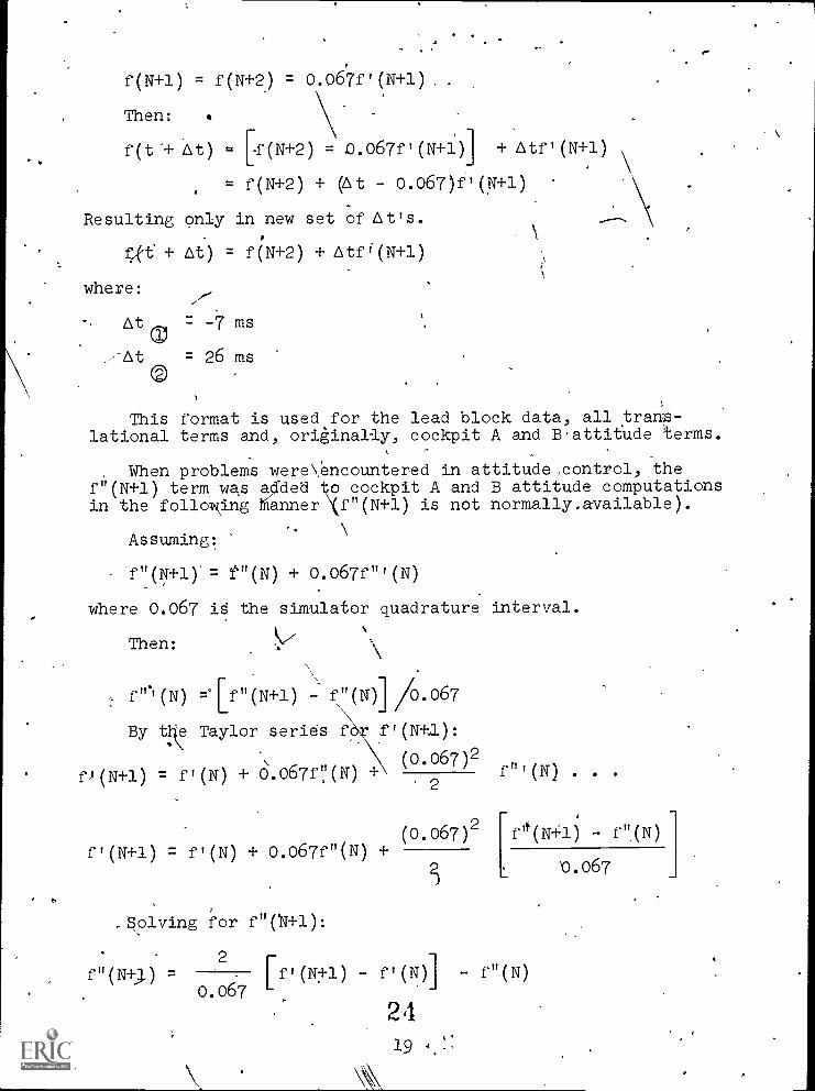
f(N +l) = f(N+2) = 0.067f1(N+1)
Then:
f(t"+ At) = [f(N+2) = 0.067f, (N+1)] + Atf,(N+1)
= f(N+2) + (At - 0.067)ff(N+1)
Resulting only in new set of At's.
+ At) = f(N+2) + Atf"(N+1)
where:
At , = -7 ms
-At = 26 msaThis format is used for the lead block data, all trans-
lational terms and, originally, cockpit A and Battitude terms.
When problems wereencountered in attitude, control, thef"(N+1) term, was a ded o cockpit A and B attitude computationsin the following anner f"(N+1) is not normally.available).
Assuming:
f "(N +l) = t"(N) + 0.067f "' (N)
where 0.067 is the simulator quadrature interval.
Then:
f"'' =1!"(N+1) - f':(N)J i/(0.067
By the Taylor series f
fi(N+1) = f'(N) + 0.067fNN)
f'(N +1) = f'(N) + 0.067f"(N)
f'(N+,1):
(0.067)2f"'(N) . . .
e(N+1) - f"(N)
2
(0.067)2+
solving for f"(14+1):
0.067
2f'(N)] - f"(N)f"(N+;) = [fl(Ntl) -
0.067
2 4

Adding the third term to the Taylor series, as previouslyemployed: A
A t 22f(t + At) = f(N+2) + Atf, (N+1) + If' (N+1) - ft (N)T-f"(N)
21 0.067
which reduces to:
f(t + At) = f(N-2) + f'(N +l) At [l +[
At At2 At2
o.06/ fl-(N) 0.067 -fn(N)-21
where all terms are availabl.e during CIG cycles and Q. ,
Addition of the TaylOr series third term re'Sulted in someimprovement in smoothness of the visual-presentation, but did notmarkedly increase roll controllability. 5ignif icant impryvementwas noted, however, in ground.control aSregards the presentationof heading changes, and their coordinationwith lateral translation.Since other problems are thought to exist in the roll controlarea, the improvement was considered significant enough to retain
.this compensation format in all three attitude axes in spite, ofthe added computation time required.
ti
It should be noted that time compensation schemes such asthis cannot eliminate the'effects pf transport delay. Eventhou'gh the freshest possible information is used in the visualpresentation, and extrapolation may be employed to time-com-pensate this information, no change in the visual scene can occuras a result of:::dontrol inputs before the transport delay timehas elapsed. The ASUPT system includes a fixed At teem, summed
into At®, and Ate whose valueis adjustable via instructor
input. Attempts to provide more visual lead via this term re- ,sulted in an objectionable lack of smoothness in the visual dis-play. Pilot preference, in fact, resulted in a "backwards"extrapolation (negative fired At) for the attitudes. Thistwas,however, predicated on pilot evaluation of roll response and isthought to be affected by the aforementiOned roll control pro-blems.
Of significant note is that transport delay and changes in(or lack of) time compensation are perceived by pilots as changedin the dynamics of the simulated vehicle. Transport delay must.,be minimized and proper compensati.on schemes utilized in simu-lators employing visual systems, espeCially where highly responsive
25 20

vehicles are being simulated. Investigations should be carriedout to de-be/mine the exact effects of transport delay and com-pensation schemes, and to determine what,-if any, methods may beused to minimize the effect of transport delay,on' thepilot'sability to control the simulator. 7/
Cue Correction
An important consideration in the/integration of a visualsystem is the coordination, in bothon.set time andform, of' .
visual cues and kinesthetic cues. The ASUPT-simulators are-equipped with a.six- degree -qf- freedom motion system and G- seats.The G-seats are capable, via air pressure activated cells.mount-ed under.the seat cushion, of slight reorientations of the pilot'sbody position with respect to the cockpit enfironment 'and of,applying differentiaI,tactile pressures to his thigh; buttpck's,and back areas.
These kinesthetic systems experience transport delays.in thesame manner as discussed for the visual system, but not necessarilyof the same magnitude. . Variable lead/lag compensation is pro-vided to the kinesthetic systems, but as was found with thevisual system, excessive lead degrades system performance.
The problem )presented is; given two. systems. (visual and}anesthetic) whose onset cues will, be presented,tO.the pilot atslightly different times, both of which are some At's behind' thepilot action initiating them, shOuld each system be independentlyoptimized, or should the faster system be "slowed downs' to cor-respond to the slower system (assuming, of course:that the slowei-
system has already been optimized)?*The solution will require.furthey investigation and analysis.
Also of interest is the form of the onset cues, Thle timecompensation equations were found to, be of sigliUcant Valuein altering the form of visual onset cues in the ASUPTsysteth. -
Essentially, in the Case of roll; the pilot's'vi8ua perceptionof roll acceleration was altered by employment of a "backwards"extrapolation term in "the visual attitude equatioris. Extensiveinstructor inputs are provided in the ASUPT system for alteringthe kinesthetic drive concepts with regard to transfer function .
..poles and gains, cue shaping functions, and cue acceptance ,or,'-rejection. Further investigation is being tarried out-concerning
the interrelationships between kinesthetic and visual Cues-'and
their effects on pilot performance.
2 a
.21

tFLIGHT ,
Attitude Control *f.10
.. ,
.
One of the major problem areas encountered during visual 4 .
integration was that of attitude control. Neither the nature ofthe problem nor the attempted solution are unique. to the ASUPTsystem.3 ifile'ploblem centered on roll. Although there was also , 7'a minor, pitch control problem while yaw was problemftee. -
\
Pitch- Dynamic pitch response to elevator movement was in-:deemed to be excessive by the acceptance test pilots.
Although pi qt- induced oscillation's, were generally not encioun-ered, excessive attention to pitCh control was required, therebyuni'ealistical'L increasing pilot workload. Satisfactory resultswere obtained, by:Ancreasing both pitch damping due to pitch rateand pitch damping due t4 the rate of change of 'angle of attack.
.
Of interest is the facI that the simulator displays a vei4'ypoorly dampedphugoid mode (unlike the aircraft)." Several attempts,largely centered on dyriamic drag modifications, were made to cor-rect tl.A.s. No successful' means was found of achieving good:phugoid damping without adversely affectirig other simulatedareas, and further efforts ,were terminated when the'modifi-cation6 to shdi-t-period pitn.damping provided afi easily con-trollable systeM.
r--
Roll - Lateral control problems' were magnified in the visualintegration task. These problems are summarized as follows:
(1) Inadequate aileron power in the low airspeed(landing appro'ach and slowflight) tegime.
(2)' Loy aileron 'stick forces in the slow flight regime.
(3) Inabilify.to dynamically control bank angle, re-suiting in roll overshoot and pilot induced oscillations.
The first two problems were satisfactorily solved by modify-ing aileron rollWwer and aileron hinge moment' coefficient in'the applicable dynamic pressu.4.e ranges..
The thirdproblem however, proved to be far more complex./-The aircraft roll axis is"characterized by relatively low inertia'and relatively high control power. Pilots expect' immediate andpositi'e response of the aircraft to control position inputs,with accelerations into and out of steady roll rates being bothrapid and smooth. The problem is further complicated when the
("!
-o
/
2722
4

44,
roll axis is being used to control laietai translation.in Orderto establish a ground track (landing api?oach):or relative posi-tion (formation flying).
4 . : 4 .. .
Initial problems were manfested by the inability to roll the-simulator.to a desired bdpk angle without.oyershpot and sub-sequent pilot-inducedkoscillations. Includedttrdre pilot commentsthat control feel was improper, and difficulty was experiencedin finding neutral stick position. While the,greatestdifficulties. were observed during formation flight andollandingapproach, roll.control was considered to be unacceptable through-
- out all flight regimes. Increases were made to aerodynamic rolldamping, (to/improve stability) and aileron roll power (to main-
. tain roll rates). Little could bedone during the integration(.effOrt with the control stick force feel,, since this is Zarqelydetermined by control, loading hardware. Aileron hinge moment
. ) per degree of aileron deflection is output from the computer to .the hardware at 15/second, but ideally this should by even higher.
i .
Figure 3 depicts stick force/position and a breakout .forcefunction deemed desirable. This involved considerable4hardware
,. redesign, and therefore,, such a function was not possible. In.
. stead, a "deadband" function was placed in the stick positiopversus aileron deflection computation (see figure 4)% - .
. .Both the breakout function and deadband functionhave the
same effect on control stick force versus roll rate; some forceis requited before any roll acceleration is developed.' The twodiffer, however, in that the breakout function does not allow anycontrol stick movement until the breakout force level has beenexceeded, ftile the deadband function allows small control stickmovements with no resulting aileron deflection or roll acceler-ation, thus improving the odds that when the pilot places thecontrol 'stick at what he feels is-the neutral point, thre villbe zero aileron deflection.
Thee changes resulted in a control response and feel satis-factory to the acceptance test pilots. Problems arose, however,
.,when pilots not previously exposed tothe system were, asked to
evaluate the simulator. All had difficulty with roll control,especially in finding and holdinethe wings:-.1evel position.This situation phenomenon had been previousWencountered. It '
seems to result from the i1pprovements which had been made in
,)roll control, during basic and visual acceptarice, combip d with
-, the large amount of simulator flight time accumulated by theacceptance test pilots thereby condi4Oning them to-the simulator.Relatively speaking, the simulator had be loe much more like th9,
airplane, and the differences in controllacaE5,kity which remainedwere not felt to be detrimental by the acceptance pilots, who
. had subconsciously learned to 'compensate human control functionsto overcome deficiencies inthe simulator. This occurred inspite of the fact that the acceptance pilots were flying T-37
i4ircraft as well as the simulator.I/ , 28
-1-
23

FORCE
CONTROLPOSITION
FORCE
a.
BREAKOUT FORCE
CONTROLPOSITION
(B)(A) AS ORIGINALLY DESIGNED(B) WITH BREAKOUT FORCE
?
Figure''; AILERON FORCE VS. CONTROL STICK POSITION
AILERON DEFLECTION
(A)
CONTROLPOSITION
AILERON DEFLECTION. .
. (A) AS ORIGINALLY DESIGNED(B) WITH DEADBAND.
CONTROLPOSITION
DEADBAND
Figure 4. AILERON DEFLECTION VS. CONTROL POSITION
29 24
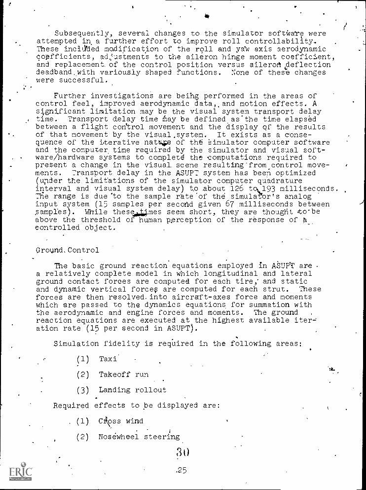
Subsequently, several changes to the simulator software wereattempted in a further effort to improve roll controllability.These incilied modification of the roll and axis aerodynamiccoefficients, adjustments to the aileron hinge moment coefficient,and replacement of the control position versus aileroft4deflectiondeadband,with variously shaped functions. None of these changeswere successful.
Further investigations are beihg performed in the areas ofcontrol feel, improved aerodynamic data,,and motion effects. Asignificant limitation may be the visual system transport delaytime. Transport delay time fray be defined.as.the time elapsedbetween a flight control movement and the display of the resultsof that movement by the visual,system. It exists as a conse-quence of the iterative natNw of the Simulator computer softwareand the computer time required by the simulator and visual soft-ware/hardware systems to completd the computations required topresent a change in the visual scene resulting from control move-ments. Transport delay in the ASUPT system has been optimized(under the limitations of the simulator computer quadratureinterval and visual system delay) to about 126 tolL193 milliseconds.The range is due 'to the sample rateof the simula-nr's analoginput system (15 samples per second given 67 milliseconds betweenampies). While thesedAIoimes seem short, they are thought o*be
above the threshold of human pgrception of the response ofcontrolled object.
Ground, Control
The basic ground reaction equations employed in ASUF'T area relatively complete model in which longitudinal and lateralground contact forces are computed for each tire; and staticand dynamic vertical force are computed for each strut. Theseforces are then resolved. into aircraft-axes force and momentswhich are passed to the dynamics equations, for summation withthe aerodynamic and engine forces and moments. The groundreaction equations are executed at the highest available iter=ation rate (15 per second in ASUPT).
Simulation fidelity is required in the following areas:
(1) Taxi
(2) Takeoff run
(3) Landing rollout
Required effects to be displayed are:
(1) Coss wind
(2) Nosewheel steering
30.25
(

(3) 'Rudder steering.
(4) *Engine-out effects
. (5) BPaking
(6)* `Adverse runway conditions (water, ice; etc.).\
-During the basic simulator acceptance (without the visualsystem), considerable effort was directed toward ground controlevaluation using the compass system and the turn and slip indi-cators to monit* simulator response. Such efforts, however, are,severIy handicariped,hen no "outside world" 1).4ual cues'are avail-able. In particular, the ability to maintain A desired groundtrack (for inst nce, the runway centerline) cannot be evaluated.
Initial ev luation of ground control with thresulted in th following major probelm areas:
4 (1) 1The simulator was found to be slow to respond tosteering inputs (nosewheel, rudder, and differential braking).Considerable amounts of pilot lead were required to obtain andmaintain a particular heading. (
sual system
(2) ,The simulator' appeared to skid whenever heading'changes were Made. Not only were heading changes required to'generate lateral ground track movement excessive, but the lateralmovement lagged the headirig and required even greater pilot leadto' maintain dsired ground track.
These problems led to an examination of the nosewheel steering/castering equations and to an examination of the*tire side forcegeneration. equations.
The T-37 nosewheel steering is activated by depressing aswitch on the-control stick, which allows nosewheel angle to be.controlled via the rudder pedals. When nosewheel steering is notengaged, the nosewheel is free to caster.
The following' nosewheel steering dynamic model had been in-stalled during the basic (non-visua) acceptance:
The nosewheel moving_away from centered position:1.
X =An demandedn .
0.5335 + 1
For nosewheel moving toward centered position:.
x = An demandedn
1.3615 + 13126

During visual integration, the following steering model wasincorporated for all steering inputs in order to speed up the
response of nosewheel angle:
Xn demanded
0.0785S + I
In addition; the location of the nosewheel steering programswas moved frOm after to/just before the ground reaction equations,thus eliminating a one-iteratipn delay between generation ofnosewheel angle and its use in the ground forces and momentscomputatiOns.
The nosewheel castering model simply sets the nosewheel angleequal. to the angle whose tangent is the side velocity of the nosestrut divided by the nose strut longitudinal velocity. Essent-ially, the nosewheel is turned to align it with the direction inwhich the tire is traveling. The only change made in this areawas to "wash out" the castering rate as the forward velocity off'
the'tire goes to zero.
The original siele.force simulation was as follows:
LIM±1 . 0LIM±A
slcidFY
= [0.76 [0 05tb FZ ..FZL or RL ord L or RL or R:
, \ [ [NN
- 0.78 0.0751fr FZN .FZN
I
LIO42 skid17Y
LIM±f
where: \\Fy = left or night' main tire side force,.LBL or R
YN= nose' tire side force, .,LB
or'R = left or right main tire slip angle, DEG
Askid'
= nose tire slip angle, DEG
skid friction coefficieht
- .F1ZL or R
= left or right main strut vertical force, LB
FZN .= nose strut vidrIbioal force, LB
27 32

%.
,
and- th
YL or R
4IN
=
=
tan -1,
tan-1
vtL or R .
DEG
1
UtL
....
vtN
or R_
DEG
UtN
v,_ = left or right main tire lateral velocity, ft/se&'L or R
= nose tire lateral velocity, ft/sec
U = left or right main tire longitudinal velocity,tL or R ft /sec '.
= nose tire longitb.dinal velocity, ft/sec,,
For conditions "inside"
main: (0.76) (0.05) =
=
Nose: (0.78) (0.075) =
the limits, the gain factors are:
ii, (LB-side force)0.038
(LB-vertical force-degree),
.1
2.1774 (LB-side force)
(LB-vertical force-radian)
(LB -side force)0.0585
.(LB-vertieal force-degree
_'3.352 (LB-side force)
(LB-vertical force-radian)
In order to improve lateral respbrise to Steering inputs, theside,f.orce generated per, unit of slip angle was, increased.
)
e-
Y 28

,
The form of the side force computations was changed to-the,following:
vtire
tire utii'eradians.
LIM ±pskid
FYFZ
tireLB
Ptire °tire]tire
where the "tire" subscript may be left main, right main, or nose,and:
N = Cornering Power,(LB-side force)
tire (Radian)
The arctan calls for IP. were eliminated for computer timeoptimization purposes, and small angle approximation ford' inradians was employed. I.
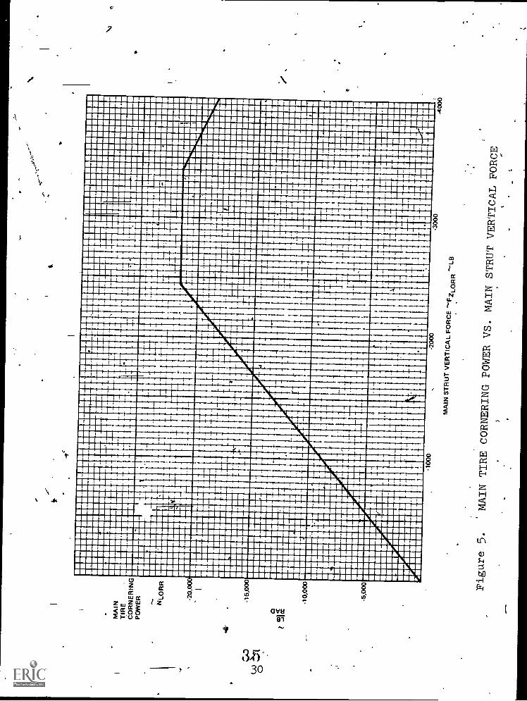
The cornering'power curves shown in figures 5 and 6 wereapproximated from equations given in NASA Technical Report R-644and were scaled down by the ratios of time 't"ertical force atmaximum gross weight.
4'
-3640 O.
NNOSE 7 [5.55FZ+ 2 [-902 Fz
N N
-21,475 O.
NL or R 8.6-5 F7 4[.76 [ -3410 - F7=.[
"L or R "L or R1
(FZ '
FZ ,
.
NN,are negative numbers.)
N L or R IN' L or R
.
r f
34. 29
1111
I114
III
III
1"11,
11111111111111"111111
I
1111
II ILA I
I11111911111111111
OMIAMOK---__M
ILIMMIKAMMMMO
111111111
EV 11 I 11:1410
Maki1,1111
..
I
liteppliiiiiiisidab
ill1111111111111111111111111111
ln1111111.11211111.11111111
IMUMMMMITIMMMITOMMIONONIONE
IMOMMEMIMIMUMMI
OMOME
"11111111111
"MORMON MOMS
WIMIM
nu.
.........
.........1....
iin:upIM
O
IIII
LA
11111111111111110 M
MOM
....111111111
..
11111111111
.111.1 1111111111111111111111191
11111
1111111
IMO
111111111
1.1111101011111
II
+MEM MIMEIMMUM10
1111111111111"
1........
°--.
.........
.....111 I
1IABM
11
1111111119111181111111111111111111111111111111111111
:1111
.111111111
SlIgN
OM
MIT
IMM
IlOrp
:::
1....
111:::: EMU MEM
-'
.N.1UM1M.UM.M1.O.M11111. OO1MU1MM11
illiiiiiiiiiiiiMIi1UMiM ::IIMME1M1M1EIM
I1I
M1I1IIIM1IM
.M:M O M
.WlilWllI"
111f1111111111111111
111
11 111
II
ill
111111111111166 4111
EM
lMMMNUMMUMEMi
II
1M
OM
MO
MM
IUM
OM
MIM
M

P
111111111111111111111111
I
I
1
111111/1
111111111111111111111111111111111
111111111111111111111
1111111111111111111111111111111111111111111111
I II
Ii
111111
11111111111111111111111p11111111111///111
I
II
I I II
11
NIMM1111111 INN&
h1101111111111111111h I IIIIIIPIIII
16
IMMO
i11111111111
1111111111111111111111111111111111111111111111111111111111111
111111111111111111111111
NIB
IIIIIIIII
III MI
1111111111111111111Praii
IMMONMEREIMMEmar
iO
NM
OMUNONO
MINIMMIM OMANI
III
1M
Oill
I ......c..
umm.....m....
III
11111111i
III 1111
Immo
.........
lon.61.
om. .........
mommimmenumnimil
IMO
MINIMMEIHNIANMENEO MO
I mil 1111 MAIN
1111=0.1. IMMEMOIN
OMMIMMOIDAMMOOMME mmeNOM
111
IleM Om
imummommumummmummmommm
iiim ME
IIIIN MN
Iillill MEI= IIIII IIIIIIIII IIIIIIIII
IIIIII2IIIIIIIIIIIIIIIIIIIIIII
IIIIIIII
III 111111111111111
MIMI IIIIIIIII
I
IMOMMUMMINIMMIL.MEMMOMMOM
Ong
IMOOM
II 'MONO
01111MEM MOMMINEEM
OINIWASIMMOMMEIMMON MO
ME MO
MO MOM IMO
MOINEOMIMEOOMOM
........................m...
me Ern
limimmumummp ........
um.
.........o........p........... ...
.11.
mismpoomp.............. ......
..,.............m........11...
mi. me .
millTrimm...... Turn
........
.........m...............
umpommilm.
gm wog
gml
.prom.....mum .........
Imummommarnm.......p.... mum Born ME me
XImMompim mom momommum
wimmommommumwommommumm mommemm mom swum mom
wm immommilm
milimmommommomemr
I.
I I
I.
1-
I

Note that for this model the gain factors corresponding tothose stated for the original model are:
(LB-side force)/Main: 8.65
(LB-vertical force-radian)
(LB-side force)Nose: 5.55
ALB-vertical force-radian)
Lore rapid-nosewheel steering' response combined withhigher side force gains solved the problems associated with un-realistic system response lags, and eliminated most of the skid-
- ding sensations during ground maneuvers. Enough skidding seri,sation remained, however, to be deemed unacceptable by the accept-ance test pilots even though the simulator was fully controllablewithout excessive pilot effort.
The source of the remaining skidding sensations seemed to beunchanged. A small amount of miscoordination,between headingchanges and lateral movement remained. In a Further attempt togain more side force rom the tires, a spring term (force pro-portional to lateral tire casing deflection) was added. Such aterm already existed, but was used only at very low forward'speeds where the slip angle computation bedomes-indeterminant.
The format was (for each tire):
St = f vt dtLIMIT ±1.0]
LLB&
vt
= true latera.1 velocity
K >> 1.0
I Ug LOWR LIM = 0.UTwv = [1.0 -
Ug = A/C longitudinal speed with respect to the groun'd,ft/sec
St = lateral ,casing stretch factor, non-dim.
NOte that the UTwv term reduced from a value of 1.0 whenward speed was zero, to zero at a forward speed of 8 ft/sec.
37 32

The side force resulting from these terms was
F = klStFZt
which was added to the side force resulting from the slip angleterm.
Ns\
and
The following modifications' were made:
10
UTWV =[ui]LOWER LIM TO 10.
St = [Kfirttd-t] LIM rfo0 ±UTITV
where: hit includes lateral true acceleration lead terms com-puted from the aircraft lateral deceleration and turn accelera-tion.
Rather than reducing to zero, the stretch factors now re-duce in inverse proportion to forward speed, and remain presentthroughout the ground speed range. In addition, the rate of sideforce buildup is increased by the presence of acceleration lead.
Again, the degree of'skidding was reduced, but the pxoblemwas not totally eliminated.
Finally,.the modification which solved the problem was en-
tirely pragmatic. The location of the visual viewpoint with re-spect to the aircraft center of gravity was moved forwardapproximately 2 feet. The result of this change is to give great-er lateral movement of the viewpoint when the simulated airdraftrotates in yaw about the center of gravity, thus compensating .:
for apparent turn /lateral miscoordination.
Spins.
Because the T-37 aircraft is used to demonstrate spins andto teach spin prevention and recovery, realistic. sidulation'ofthe complete spin regime is required in the ASUPT simulationsystem. Simulation of the spin maneuver may be broken down intothe following areas and requirements:
(1) Entry (deliberate) - proper coordination"of r011,yaw, and pitch angles and rates, and proper transition fromoscillatory to stabilized spin.
(2) Free spin"(rudder neutralized) - proper attitude,,heading rate, and descent rate. 1
33
r
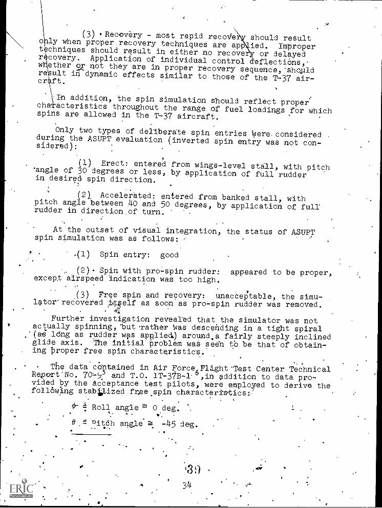
(3) Recovery - most rapid recolie should resulto ly when proper recovery techniques are app ied. Impropert chniques should result in either no recove or delayedrecovery. Application of individual control eflectiOns,-w ethero not they are in proper recovery sequence,'shoald
result in dynamic effects similar to those of the T-37 air-cr. ft.
In addition, the spin simulation should reflect propercha acteristics throughout the range of fuel loadings for whichspins are allowed in the T-37 aircraft.
Only two types of deliberate spin entries were. consideredduring the ASUPT evaluation (inverted spin entry was not con-sidered):
6
(1) Erect: entered from wings-level stall, with pitch'angle of 30 degrees or less, by application of full rudderin desired spin direction.
(2) Accelerated: entered from banked stall, withpitch angle between 40 and 50 degrees, by application of fullrudder in direction of turn.
. -
At the outset of visual integration, the status of ASUPTspin simulation was as follows: /
.(1) Spin entry: good
(2) Spin with pro -spin rudder: appeared to be proper,except airspeed indication was too high.
(3) Free spin and recovery: unacceptable, the simu-latorreCoveied I0elf as soon as pro-spin rudder was removed.
4'';)
Further investigation revealed that the simulator was notactually spinning,*but.rather 'was descending in a tight spiral'(as ldng as rudder wps appliedt) around.a fairly steeply inclinedglide axis. The initial problem was seen to be that of obtain-
. ing proper free spin characteristics.'
The data contained in Ait Force,Flight"Dest Center TechnicalRepoTt'No. 70-95 and T.O. 1T-31B-1-',in addition to data pro-vided by the Acceptance test pilots, were employed to derive thefollowing stabl.lized free spin characteristics:
.
0- = Roll angle 0 deg.
0 = Ditah angle -45 deg.
34
*
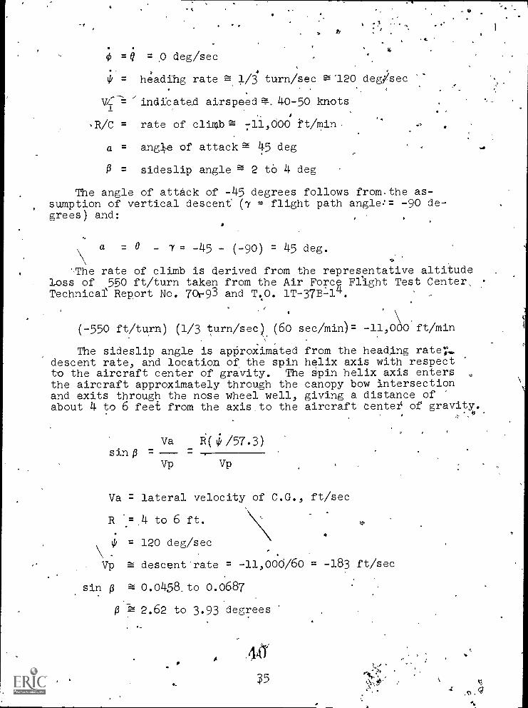
0 =Q = p deg/sec
0 = headihg rate 7-z-- 1/3 turn/sec 95'120 deg /sec
/indicated airspeed =. 40-50 knots
,R/C = rate of climbs= 711,000 ft/min,
a = angle of attack = 45 deg
P = sideslip angle = 2 to 4 deg
The angle of attack of -45 degrees follows from.the as-sumption of vertical descent (7 = flight path angle:= -90 de-grees) and:
a = 0 - 7 = -45 - (-90) = 45 deg.
The rate of climb is derived from the representative altitudeloss of 550 ft/turn taken from the Air Forc Flight Test Center.Technical Report No. 70r93 and T.0. 1T-37B-14.
%AI
(-550 ft/turn) (1/3 turn/sec) (60 sec/min)= -1100 ft/min
The sideslip angle is approximated from the heading rate7..descent rate, and location of the spin helix axis with respectto the aircraft center of gravity. The spin helix axis entersthe aircraft approximately through the canopy bow intersectionand exits through the nose wheel well, giving a distance ofabout 4 to 6 feet from the axis to the aircraft center of gravity.
Va R ( / 5 7 . 3 )
sin p =
Vp Vp
Va = lateral velocity of C.d., ft/sec
R -= 4 to 6 ft.
0 = 120 deg/sec
Vp = descent rate = -11,000/60 = -183 ft/sec
sin p 0.0458,to 0.0687
2.62 to 3.93 degrees
441

r 4*4
Frian'Euler rates (8 =.0 = 0,Sik = 120 deg/sec), the .stabilitytaxis angular rates (ps, qs, rs) may be, computed as:. ,
stability axis roli'rate = 2.1 ra-d/sec',
als axis pitch rate = IJ rad/sec
rs
= stability_ axis yaw rate = 0 rad/see. .
. .Note that the pure Eider axis yaw rate :is rotated 90 de-grees and becomes-pure stability axis roll.ate; that" is, theaircraftrotation is<about the vertically driented X stabilityaxis.
The problem .now betomeS one' ofodetermihing the values ofroll, yaw 'anti side force coefficients due to beta and stability
_aXis'rollrate (stability axis turn, rate 16 zero) which willSolve'to zero at a, .= 45° for the given beta 4nd roll rate. Dueto the assumption of all angular accelerations being zero, andbecause qa 0 and Ixz is small, inertial coupling is not a
factor e roll and yaw computations. The yawing moment dueto sid e applied at a forward center gl'avity loCation (26%C.G. ssumed) was included. The process was simplified byusing the betatoefficients already existing in the simulator.These coefficients were specified by the airframe manufacturer's .
high-angle-of-attack data(no high-angle-of-attack data were' given for angufar.rate coefficients).
The results of these .computations were values of C. Ind
'7;Cn- at angle of, attack 45°. The value of C
n showed allow.Ps p
smagnitude but of reversed while Ci reduced, to low mag-
;-p -4,--.
.nitude, but maintained its sign. These values were incorporatedbyyStraight-lining etwptn the coefficient values previouslyused at a. =.20° and" the -new coerficient values at a = 450'.jaecause of'the'manner in'which they are programmed in the simu-iator, it was convenient to.maintain the.value of,C1 constant.
, 1 Ps
o .for Angles of. attack greater than 45., but to continue the 'slopeof Cn versus a for, angles of attack greater than 45 degrees.Ps
,These changes resulted in the, simulator entering a "flat"in of very high heading 'rate at about -10 degrees 'pitch'. and
+ 0.degrees 'angle of attack. The r \ason for this was seen, when'total pitch moment (including inertial' coupling effects), was
36 41
4

plotted versus'a- . Two zero values were obtaihed. The.first,-at 30°, had an unstable slope, while Oe second, ata 80°had a stable slope. The high-angle-of-attack pitch moment coef-.'ficient was then recomputed in order to move the lower-angle-of-attack zero-point from a = 30° to a = 45°. While the simulatorwould still not stabilize at a = 45°, it could be "flown" atthat angle of attack by judicious use of elevator control, andthe validity ,of. the lateral-directional coefficient changes wasverified for a =.450.
Attempts to modify the pitch moment slope at a= 45° by tail-oring the-Egh-angle-of-attack baspitching moment coefficient(Cm vs..a ), resulted in curves which were obviously' unreal, and
therefore hot programmed. Successwas obtained by,tailoring-CI (roll damping coefficient), thus controlling pitch. attitude
Psthrou the very powerful aircraft axis roll and yaw rate in-ertial coupling into pitch acceleration. The technique wad toreduce C1 to near zero at a = 400, increase it to'the,computed
"trim" value at a = 45°, then increase the damping sharply above45 degrees. Thus, as a tends to reduce from 45 degrees, stabilityaxis roll damping reduces and,stability alas roll rate increases.This result6 in an increase in bOth,aircraft axis roll and turnrates, causing a pitch-up moment through the Inertial couplingin the pitch acceleration equation, and a is driven back up toward45 degrees. For a tending to increase above 45 degrees, theopposite takes place. The stability axis roll damping increases,
-thus reducing the stability' axis roll rate, and aircraft axisroll and turn rates. The amount of inertial coupling pitch-upis reduced, and a is driven back down toward 45 degrees.
"-While these changes,solved the free s14.n problem, they didnot provide good recovery characteristics and had adverse ef-fects on entry characteristics.
. .
The T-37 spin entry consists of combined pitch down and roll/yaw in the direction of applied rudder-suc'.h- that the pitch angle(0) passes, through, mines 90-degrees with bank angle-(0) at, or,near the inverted position as 0= -90° is.approached. The pitchangle then 'rises to about horizon level with roll angle at aboutzero degrees;:folloWed byseveral pitch/roll and yaw rate oscil-lations of decreasing magnitude until the stabilized spin isestablished after three to five turns. The erect entry ratesare 'somewhat.higher than the accelerated entry rates, but' inneither'case does the motion appear (visually) to be violent.Rudder is normally released as soon as the establishment of aspin is verified, but pro -.spin rudder (with full aft stick) hasonly relatively small effects on heading rates and attitude.The stick is maintained in the full aft position until recovery.
=
4 a37

11.
Recovery is achieved by application of full anti-spinrudder and, one turn later, full forward stick. The rudder isheld until rotation ceases', and the stick is held until the air-craft flies out of the stalled condition in an approximately ver-tical (or past vertical) dive. All recovery control applicationsare rapid.
At entry, the simulator' tended to snap-roll into the spin;then displayed violent roll, yaw, and pitch oscillations as longas pro-spin rudder was held. When the rudder was neutralized,the oscillations took eight to ten turns to reduce to small(±590 and° excursions. Upon application of anti-spin rudder,recovery was immediate and full forward stick was not required.
The violent entry wad corrected by adjusting the roll andyaw beta coefficients. The original simulation of C1 (roll due
a
to beta), expressed as a function of angle of attack, containeda slope change at a = 8°, which resulted in very large magnitudesof C1 at high angles of attack (40 to 50 degrees). This change
0
in slope was removed thus reducing the magnitude of C1 by a factor
of -about three in the spin angle of attack region. The Cn
simulation contained a term, commencing at a = 11° and increasingin magnitude proportionately to a above 11 degrees, which caused.Cn to become nonlinear with respect to beta and divergent for
large betas.. This was also removed, and the low-angle-of-attkkscope of Cn versusa was maintained in the high-angle-of-attack
region. The0
effect of these changes was most apparent in thespin entry, where sideslip angles as high'as 20 degrees were
-generated. by rudder application. Chahging Cn changed (slightly) the
'sideslip. angles obtained to abodt 16 to 18 degrees, while theC change greatly reduced the roll resulting from that sideslip,
thus slowing down and smoothing out spin entry. Little effect-.was noted in the free spin, due to the much smaller sideslipangles and the overwhelming effects of the previously mentionedroll/yaw due to roll rate poefficient changes. Thee recoverycharacteristics were improved somewhat (that is, recovery be- )
came slightly slower) due to the reduced effectiveness of side-slip angle changes induced by rudder applications, but the sim-ulator would still recover in less than one, turn with rudderalone.
This problem was approached via adjustments to the high-angle-of-attack roll, yaw, and side force coefficients due to rudderdeflection. The airframe manufacturer's data specifies valuesfar these coefficients at angles of attack of minus 4 degrees andplus 8 degrees. The original simulation consi.sted of straight--lined functions connecting these &eta points and continuing,
384,3
;,, with constant slope, into the higher angles of attack. The yawmoment and side force coefficients display slopes' of'increasing....)magnitude with increasing angle of attack, while the roll momentcoefficient has a relatively steep slope of-decreasing magnitude,resulting in a reversal of sense and large magnitudes of rolldue to rudder in the, same direction as rudder. deflection in thespin angle of attack region. All three rudder coefficients pro-vided strong recovery tendencies, with the roll coefficient beingpredominant. Multipliers were developed which reduced the mag-.nitude of eacit term as a function of angle of attack above 35degrees. A great deal, of experimentation was required to establishmultiplier functions which would provide proper recovery char-acteristics while having minimum impact upon entry character-istics. The final functions resulted in the following rudderonly recovery characteristics:
Fuel Weight Turns to Recovery (Rudder Only)
600 lb
1400 lb
1 -tc. 1.5
4 to 6
The efforts to maintain entry characteristics while adjust-ing rudder coefficients to obtain proper recovery characteristicswere-not entirely successful. While the erect entry was stillacceptable; the accelerated entry was deficient in both nose-down pitch and roll-off. In addition,'acceptance pilots hadnoted that the power-off and power-on stalls no longer displayedsufficient nose-down pitch.
More roll-off during spin entry was obtained by increasingroll due to turn rate (C
l) as a function of angle of attack
r
above 30 degrees. Also, investigation showed that spin entrieswere improved as the high-angle-of-attack basic pitch moment co-efficient was made more negative in the 16- to 40-degree angle,ofattack range. The limiation here was nose-up elevator powerand inertial pitch effects available to drive angle of attackinto the spin region. It was very easy to make cm negativeenough to Rrevent spin by never allowing angle of attack to reach
the 40- to-50-degree range.
Basic pitch moment was then readjusted with the 16- to 25-degree angle of attack values determined by pilot evaluation of
stall pitch over characteristics, tfte 25 to 40 degree valuesdetermined by spin entry characteristics and the 45 degree value
as determined previously4for free spin pitch trim.,
Figure 7 traces the'evolution of high-angle-of-attack basic
pitch coefficient.
44
39

During these final phases of spin work, the acceptance (:pilots'reported several instances of inconsistent entries andrecoveries, including failure to enter a spin, rapid recovery,and failure to recover.) A complaint was also received that the"B" cockpit would not spin to the left or recover'from a Tight
.,, spin., The latter problem was corrected by maintenance: (The"B" cockpit left rudder pedal forward pedal stop had been mis-adjusted..) The former problem was noted in both cockpits andproved to be more difficult.
Investigation revealed that extremely large magnitudes of roll/ due to aileron deflection (C1 ) were present at high angles of
attack. This coefficient had been developed in the same manneras the rudder coefficients, and had a very large increase inmagnitude with increasing angle of attack. A 90 percent reductionin C1 was made in the high-angle-of-attack region, and the pro-a
blems was solved. The apparent cause had been a tendency ?orpilots to make small 14T:al stick movements as full rudder wasapplied-for spin entry or recovery.
AD.
Two more changes were made during spin development which,while not necessary to the aerodynamic development,of spin motion,are important to the pilot's conception of spih cfti'acteristics.
16° a as°
. CMBASIC
.V.. .
\ N.\
I%N.
. I),
\ C.\ N.L......7..L.le
\ -----4'1N
\r- \
: \\ :\' \ I \
. \(1) COMPUTED SPIN TRIM Cma ' \ \
LOW ANGLE OF ATTACK CMa ?) 9 ®0 - -- Cma AT START OF VISUAL INTEGRATION
0 - Cma AS ORIGINALLY WRITTEN T,0 OBTAIN'
SPIN PITCH TRIM0 .. . FINAL .Cma
Figure 7. BASIC PITCH COEFFICIENT VS. ANGLE OF ATTACK,° 40 4 5

Tke first was to obtain roper airspeed indications at veryhigh angles of attack. The 7 aircraft indicates 40to 50knots of airspeed in the stabilized' spin. In the simulationsystem, the indicated airspeed is derived from the total velo-city vector magnitude, which is largely made of an inertialvertical velocity of about 180 feet per second during the spin.
In the 15,000 to 20,000 foot altitude range, this converts toan indicated airspeed of about 90 to 100 knots. Since no high-angle-of-attack pitot/static system recovery data was available,a high-angle-of-attack indicator error function was empiricallydeveloped to reduce airspeed indications to the proper range.
The second change involved elevator hinge moments. In theaircraft, stick forces become light and the stick moves backagainst the full-nose-up stop during the'spin. High-angle-of.attack functions were added to the elevatorihinge moment com-pdtations to obtain the desired results.
No claim is made for validity of the aerodynamic coef-ficients developed during the ASUPT spin evaluations. Obviously,most changes were of a gross nature, made in response to problems
as they arose. The only justification is that the resultswere better than originally expected. While the system is con-sidered to be usable for spin demonstrations and recovery train-ing, some problems are known to exist and some configurationswere not investigated. These are as follows:
(1) Attitude The simulator presntly Spins at pitchangles between -35 and -40 degrees with ang1ei of attack ofabout 50 degrees. Both parameters are about 5 degrees nosehigh.
(2) Stick - No stick buffet is simulated for stall' orspin.
(3) Light Fuel.Loaas - Recovery may be too rapid withfuel loads of less than 800 pounds.
(4) Asymmetric Fuel Loading---TheT-ettects-of wing ,fuel-imbalance were not .investigated.
(5) InverW Spins - These were not considered.
(6)- Nondeliberate Spins - No attempts were made toinvestiage spin entries-from accelerated or deep stalls wthout,the application of rudder.
Formation Flight
The ASUPT Computer Image Generation System contains a select-'able data base which consists of a T-37 aircraft and limited '
ground detail. Extensive shadingis employed to present theflat Plane surfaces stored in computer memory as ''curved surfabes'
in the visual display. Detail level includes insignia, clearcanopy with canopy 'bows, "student pilot and instru4or heads,
/4.1 46
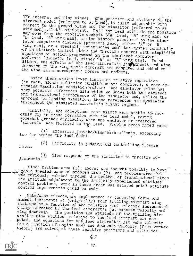
VHF antenna, and flap hinges. iThe.position and attitude of theaircraft model (referred to aslead),is fully adjustable withrespect to the ground plane and the simulator (referred to aswing man)'pilot's viewpoint. Data for lead attitude and positionmay come from the oppbsite cockpit (PA" lead, "B" wing man, or"B" lead, "As' wing man), a time history prestored on the simu-lator computer's discpack (prestore lead, either "A" or "B"wing man), or a specially constructed emulator system consistingof an attitude control stick and throttle control with simplifiedequations of motion programmed in the simulatot computer'ssoftware (Emulator lead, either "A" or "B" wing roan). In ad-dition, the effects ,of the lead'aircraft's jelftxhaust and wingdownwash on the wing man's aircraft are computed and added tothe wing man's aerodynamic fOrces and moments.
Since there arekno lower limits on relative separation(in fact, midair collision conditions are computed), a very de-manding simulation condition'exists: the simulator pilot hasvery accurate references with which to judge both the attitudeand translational performance of the simulator and, unlike theapproach to landing situation, these references are availablethroughout the simulated aircraft's flight regime.
the acceptance test pilots.were unable to-smo-othly fly in close formation with the lead model, havingsomewhat greater difficulty when the emulator or prestored"aircraft" was selected as th,lead. Problem areas noted were:
(1) Excessive_jetwake/wing'wash effects, extendingtoo far behind the lead model.
(2) Difficulty in judging and controlling Closurerates.
(3) Slow response of the simulator to throttle ad-justments.
. Since problem area (3); above, was thought possibly to }eveCesP of problemapea(2)---ttndproblem-arealwas ob-viously related through the-control of translational ratesvia attitude adjutment to the irttially experienced attitudecontrol problems, work in these areas was delayed until attitude
control improvements coul4 be made.
Wake/wash effects, are implemented-by computing force andmoment increments at (originally) four trailing aircraft wingstatiqns asa. function of the relative wind velocity incrementalchanges created by the -lead aircraft's jet exhaust velocity andwing downy/ash. The position and attitude of the trailing air-craft's wing stations relative to the .lead aircraft are com-puted, and equations for the lead aircraft's jet wake velocity(as a function of engine RPM) and downwash velocity (from vortextheory) are solved) at these relative positions and attitudes.
4'i
42

st.
When theeffects were reduced, in compliance wAh pilotcomment, it was found that reduction ire the number of wing'stations considered from four to two did not degrade the simu-lation, and saved a relatively large amount of valuablecomputation time (wake/wash effectS are computed in a loopl,executed once for each station, and involve considerable amountsof computation time in determining relative position andattitude). -
The formation flying simulation was again evaluated bythe acceptance test pilots after the above wake/wash changesand attitude control improvements had been implemented. The-system had improved to the point of being flyabile in close for- .
mation, but problem areas (2) and (3) were still obvious. Pro-blem (2) was vastly improved by changing iteration rates on boththe formation flying computations and_the simulator latitude/longitude modules to 15 iterations per second. Originally,these had been computed at 7.5 iterations per second, whichwas quite sufficient (in the case of latitude/longitude) for 'alltasks except formation flying .(no noticeable improvements intaxiing or take off and landing performance were noted whenthese changes were made). Acceptance pilots were now able tofly close formation maneuvers smoothly, with the exception oflongitudinal positioning: throttle response was still consider-ed poor.
A totally pragmatic solution was tO.add a small drag function',,computed from the difference between. demanded engine RPM (throt-tle position when the engines are fired, windmialing RPM whenunfired) and actual engine RPM, thus providing thrust "lead".In addition, the thrust loss due to the thrust attentuators(devices which extend into the engine exhaust'stream when speedbrakes are extended at near idel engine speeds) was increased.These changes provided the desired longitudinal accelerationcontrol.
When pilots unfamiliar with the simulator evaluated the sys-tem (see section on Attitude Control), some difficulty with for-mation flying was experienced. These problems seemed to be a.
r o-1---przstyre rns , rathertrahdeft cienc't ethe formation flying simulation itself. Some difficulty, stillexists in judging closure rates, but the lack or-fine detail(seams, 'rivets, flight control positicns, etc.) on the visiallead aircraft model may be a significant cause.-
-
RECORD/PLAYBACK (R/P)
Incorporated in the basic simulator advanced training Soft-ware is a system for recording a mission and playing it back.Specifications required that this system.be capable of 90 minutesof recording time with fully realistic replay at iteration ratesof 1.875'(SLOW), 3.75 (NORMAL), and 7.5 per second (FAST). Thissystem records, on the computer system magnetic tape, criticalsystem (flight, nav/com, and advanced training) discrete and ana-log inputs such as flight controls, console switches, etc.,
43 48
a 3.75/secgnd rate. While NORMAL was the usual replay mode,SLOW could be employed to 'allow an,pbserver to more closelyexamine or feel a particular portion of the recording for pur-poses of evaluation or experimentation. FAST was primarilyused to more rapidly position 'the re-cording to the area ofinterest. SLOW was accomplished by halving the module inte-gration ratesland slowing the replayed data to 1.875/second,FAST was dorie by doubling.
In addition to meeting its requirements, this scheme pro-duced a suitable realistic playback via aircraft instruments,'controls, and the motion system. This, however, was not thecase after integrating the visual with its increased sensitivity.Attit:ade changes were extremely jumpy and trdnslations had ex-cessive stepping. Therefore, this technique was not acceptable.The cause of this is obvious when considering that the R/Psystem ;eras recording aid replaying only one-fourth of 'the 15/second flight system control inputs.
The obvious solution to increasing visual playback fidelitywas to record data at faster rates, ideally 15/second. Systemresources (time and tape space) would not, however, allow a15/second rate, but could accommodate a 7.5/second rate if therequirement fora total record time sof i-%) minutes was reduced to45 minutes. This compromise was made. Sg'oftware modificationwas implemented to the RIP system to increase SLOW to 3.75and NORMAL to 7.5. FAST remained at 7.5, but without doublingthe integration constant. Thus, FAST.was functionatly. elimi-nated .(although the hardware controlsoaA'the AIOS remainedfunctional). The result was a 50 percent increase in visualplayback fidelity with only a noticeable stepping during high-rate maneuvers and rapid flight control activity. Since highrates are encountered IQ only a'minimal portion of the trainingsyllabus, this modification was.considered subjectively accept- .able. The only negative effect from, reducing the total taperecord time to 45 minutes was that of maintaining and control-ling a larger R/P tape, library.
As._mentioned above, a NORMAL R/P rate of 15/second would' have been the ideal. However, since tape resources (time andspace) could not meet this additional load, another larger andfaster media, the disp, would have been necessary. Althoughthe basic'system was configured with a 24-megabyte disc;,it wasalready dedicated to other system-users and'spare space wouldnot accommodate the additional R/P requirement,s. Therefore,this approach was rejected. It would, of course,'have beenpossible to .add another disc unit since the system has this ex-,pansion capability. This, however, would have required consid-erably-more software modification, together with the cost ofadditional hardware. Both would have severly impacted the pro-gram and the schedule:
.
4 '9
44

SUMMARY
The ASUPT/CIG hardwire/software integration effort, whichcommenced in October of1974 and was completed in January of1975, consisted of interfacing the basic simulator computer withthe visual system computers, upgrading simulator systems to pro-vide quality dynamic information to the visual system through-out all flight regimes, and total integrated system testing.
j This report provides description of the problems encounteredduring the above inte ration phases. Each problem is presentedin detail together th its solution.
It is apparent that some solutions have not completely re-solved the related problems. However, the presentation effectshave been minimized to an acceptable level. Such solutions werenecessitated by the economics of the situation, where a completesolution would be too costly. One of the purposes of a reportsuch as this is to communicate to others the problems and pro-gress made on such endeavors so that in future undertakingsthey can address themselves to the problems described hereinat an early stage and provide proper and complete solution.:Ibis report fulfills that objective.
45

REFERENCES
1. Larson, D. F. and Terry, C.. ASUPT-76, ASUPT Simulator/ComputerImage Generator Integration Acceptance Test Guide, Singer-SPD,Binghamton, N.Y.
2. Hickling,.X. ASUPT-59, Interface Control Document ASUPT Simulator/Computer Image Generator Integration. Singer-SPD, Binghamton, N.Y.
3. O'Connor, F.E., Capt. USN; Shinn, Dr. B.J.; Bunker, Dr. W.M.1"Prospects, Problems and Performance-A Oas$ Study.of the FirstPilot Trainer Using CGI Visuals,' Document No. 73ASD05, November1973. General Electric'Co., DaytonaBeach, Florida.
4. Smiley, Robert F.; Horn, Walter B. "Mechanical Properties ofPneumatic Tires With Special Reference to Modern Aircraft Tires,"NASA Technical Report R-64, 1960.
5. Fronter, Maj. Jarry D.; "T-37B Qualitative Spin Tests", Air ForceFlight Test Center TechnicalReport No. 70-9, April 1970.
6. T.O. 1T-37B-1, "USAF Series T-37B Aircraft Flight Manual".,
46

a
APPENDIX A
-ASUPT TECHNICAL FACT SHEET
524
47

AIR FORCE
U
MA
R
AFNRUFT TN 73 -01
ADVANCED SIMULATION
IN
UNDERGRADUATE PILOT TRAINING
(ASUPT)
TECHNICAL FACT SHEET
By
Frank E. Bell, III
1.
/
FLYING TRAINING DIVISIONWilliams Air Force Base, Arizona 85224
. May 1974
LABORATORY35,
a AIR FORCE SYSTEMS COMMAND
MOORS AIR FORCE RASE, TEXAS
53 1
48

The Advanced Simulation in Undergraduate Pilot Training (ASUPT)program is a joint effort of two divisions of the Air Force HumanResources Laboratory (AFSC) being conducted under the leadership of
the following individuals:
Hq Air Force Human Resources LabratOry, Brooks AFB, TX
Colonel Harold E. Fischer, CommanderDe /Howard L. Parris, Chief Scientist
Flying Training Division, Willians AFB, AZ. /
Lt Colonel Dan D. Fulgham, ChiefOr William V. Hagin, Tec 'cal Director
Mr James F. Smith, Chief, simulation Applications Branch
Advanced Systems Division, Wright-Patterson AFB, OH .
Dr Gordon A. Eckstrand, DirectorMr Carl F. McNulty, Chief, Simulation Techniques Branch
Mr Don R.. Gum, ASUPT Program Manager
This technical summary of the system provides a ready referenceto the capabilities of a unique Air Force training research device.
5449

FLY
ING
TR
AIN
ING
- D
IVIS
ION
Will
iam
s A
PR
, Aru
sn
*Of
CO
CK
PIT
'A'
IL
.CO
CK
PIT
_
ti
A
CO
N V
105
'B:
Mos
cor
so.
AD
VA
IMM
D 2
111L
AT
OO
UN
DO
KO
AD
UA
lt P
ILO
Tm
imic
Com
kplts
s-
14 %
who
m
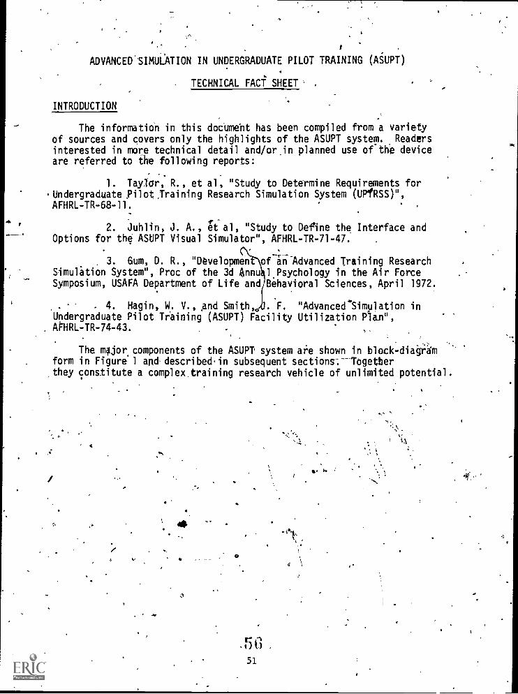
ADVANCED.SIMULATION IN UNDERGRADUATE PILOT TRAINING (ASUPT)
TECHNICAL FACT SHEET' .
INTRODUCTION
The information in this doeumebt has been compiled from a varietyof sources and covers only the highlights of the ASUPT system. Readers
interested in more technical detail and/or.in planned use of the deviceare referred to the following reports:
1. Taylor, R., et al, "Study to Determine Requirements forUndergraduate Pilot.Training Research Simulation System (UPfRSS)",AFHRL-TR-68-11.
2. Juhlin, J. A., et al, "Study to Define the Interface andOptions for the ASUPT Visual Simulator", AFHRL-TR-71-47.
3. Gum, D. R., "Developmen of Training ResearchSimulation System", Proc of the 3d Annu 1 Psychology in the Air ForceSymposium, USAFA Department of Life and Behavioral Sciences, April 1972.
4. Hagin, W. V., and Smith, . F. "Advanced'Simulation inUndergraduate Pilot Training (ASUPT) Facility Utilization Plan",APHRL-TR-74-43.
The major. components of the ASUPT system are shown in block-dia4i4mform in Figure 1 and, described.in subsequent sections:--Togetherthey constitute a complex, training research vehicle of unlimited potential.
4
a
t'

CRT
ASUPT BLOCK DIAGRAM
VISUAL
SYSTEM
c.,
LN.
CRT
0\
COMPUTER
'
T-378
IIi
IMAGE
COCKPIT
\GENERATOR
CRT
'ELEC
TRONICS
MOTION
SYSTEM
tJ"1
IV
CS
CONVENTIOWt.;
IOS-
SPECIAL
PURPOSE
COMPUTER
GENERAL
PURPOSE
COMPUTER'
GENERAL
PURPOSE
COMPUTER
4111
-4
CRT
.CRT.
ELEC
TRONICS
VISUAL
SYSTEM
CRT. T-378
COCKPIT
PERIPHERALS.
PERIPHERALS
MOTI
SYST
ADVANCED
ONVENTIONAL
IOS
IOS
FIGURE 1
"COMBINED" IOS

KINESTHETIC SIMULATION
ONSET CUES
A synergistic six degree-of-freedom motion system has been selected.
for ASUPT. Each motion platform is driven by six hydraulic actuators
and has six passive actuators for safety purposes. The actuators have
60" travel and together provide the following displacement capabilities:
Vertical
Lateral
Longitudinal
+ 38", - 30"
± 48"
+ 49", - 48"
Bitch
Roll
Yaw
+30°,
±22°
±32°
-20°
These excursions, in turn, are sufficient for onset cues (with,
subsequent washout) of the following magnitudes.
Vertical .± 0.8 g Pitch ± 50°/Sec2
Lateral ± 0.6 g Roll -± 50°/Sec2
Longitudinal ± 0.6 g Yaw ±-50° /Sec2
Total Payload: 17,000 lbs
Total Weight on Floor: 26,500 lbs
SUSTAINED CUES
The left-hand.(student's) seat in each cockpit consists of 31pneumatically driven, individually controlled elements:
Seat Pan - sixteen 4" x 4" cells
Back Rest - ,nine 5" x 7" cellsThigh Panel - three wedge-shaped cells on the outer side of
each thigh.
In addition, the tension in the student's lap belt is varied bia
small actuator. By altering the contour of the seat pan and back rest
in the "G-seat" and by changing the force exerted by the lap belt,.thesustained pressures sensed in the back, buttocks, thighs, and abdomen.
during flight are simulated.
r D
53

VISUAL,SIMULATION
Each cockpit is virtually enclosed within the seven-channel displaysubsystem (see Figure 2). Each channel consists of a cathode ray tube(CRT and a set of in-line optics (Figure 3). The-optical componentscollimate the light rays to provide an infinity image and match the scenesfrom adjacent CRTs to produce a continuous field-of-view which essentiallyduplicates that of a 1-37 aircraft: ±150° horizontally and +110°,-40° vertically (Figure 4). The computer generated imagei appear on theappropriate CRTs, depending on the lbcation and attitude of the aircraft.The ASUPT visual system is unique in that it. presents relatively complexscenes in proper perspective over a very large field-of-view during un-programmed flight paths anywhere within a 500 nautical mile by 500 nauticalmile by 100,000 foot airspace.
The CRTs used in the display system are the largest ones in existence,with an overall length of 40" and a chordal diameter of 36". The face-plate is part of a spherical surface 48" in diameter and subtends an 80°angle. Noteworthy features,of, the tube and its electronics include 1023scan lines, 10Q0 elements/line, 30 frameS/second, 7 arc-minute retorution,and 600 foot-114mlairts highlight brightness. PT462, a high-efficiency,green-tinted phospher which matches the spectral characteristics of theoptics well, is used-to produce monochrome scenes.
The passage of images through the optics is illustrated in Figure 5.The polarizers and filters allow the wanted (infinity) image to betransmitted to the pilot while extinguishingthep real image and multiplereflections. The path which the wanted image travels results in asignificant lOss in brightness: the transmitsioniefficiency is approxi-mately 1%. The highlight brightness seen by the pilot, consequently, is6 ft-lamberts.
The computer image generator (CIG) produces scenes in the followingManner. Each Object to be displayed is modeled as a set"of convex .'polygonal surfaces. Specifically, the X, Y, and Z coordinates of eachvertex of the object are, stored on disc alopgiwith information associatingthe vertex with an edge, the edge with a plane polygon, and the polygon .with the object. As the arrcraft moves thrOugh the environment the computerextracts from mass storage only the edge data. in the immediate vicinityof its current position. This eliminates processing of data for objects,obviously too distant to be seen and allows the number of stored edges'to be many times the number of edges actually displayed.
The potentially,visible edges are geometrically projected ontq sevendisplay planes in'order to determine in which channel each is to appear',The intersections of the edges with the scan lines are then computed,priority confliCts resolved, and ""gray shades" assigned to the individualraster elements.
5
54
-The ASUPT CIG is capable of displaying 2000 edges, which may allbe used in one simulator or may be shared in any desired ratio betweenboth. For example, tf an airwork sortie is underway in cockpit A andtraffic pattern practice in B, 500 edges may be processed And displayedfor A, 1500 for B. A and B need not be operated within any limitedgeographic region of the environment Model; each is free to fly inde-- .
pendently. Special effects such as atmospheric haze and ceilings areincorporated in the System, as are three versions (day, dusk,,and night)of the basic model. In addition to fixed objects, the system can displaya "moving model" (e4., another aircraft) for formation or one-on-onetraining.
The delivered'environment model will contain approximately 100,000edges'. The local area of Williams AFB and its auxiliary field, the T-37contact practice areas, and a 50-mile perimeter around these regions willbe modeled with all significant landmarks and features. -Surface patternswill occupy the remaining area out to the boundary of the 500 by 500 NMregion. Both the simulator and the CIG-have been designed for eventualexpansion to an area 1250 by 1250 NM. Changes or additions to the modelare easy to make for research or training purposes. No other imagegeneration technique shares this flexibility.
13
55

MO
TIO
N1I
rAS
E P
LAT
FO
RM
DO
DE
CA
HE
DR
AL
SU
PP
OR
T S
TR
UC
TU
RE
V.%
00E
t4
6 )A
tt3V
OS%
'
SIM
ULA
TO
R C
OC
KP
IT FIG
UR
E 2
VIS
UA
L D
ISPL
AY
CO
NFI
GU
RA
TIO
N
VIS
UA
L D
ISP
LAY
MO
DU
LES
N
SU
PP
OR
T T
RIP
OO
S

N.
FIG
UR
E 3
I ,
Cro
ss S
ectio
n' o
f T
ypic
al F
arra
nd I
n- L
ine
Infi
nity
Win
dow
l
I
0

80 60 40 20
,..A
FT
0...
..-'
20 40 60 80
IP
WIN
DS
CR
EE
N O
UT
LIN
EF
RO
M N
OR
MA
L H
EA
DP
OS
ITIO
N.
ZE
NIT
H
1
WA
.0.
...
-r--
i
180
150
120
9060
-
FIG
UR
E 4
°
30O
3060
LOW
ER
VIS
IBIL
ITY
LIM
ITW
ITH
HE
AD
MO
TIO
N
9012
p
VIS
IBIL
ITY
DIA
GR
AM
(PIL
OT
'S P
OSI
TIO
N4
. *
150
/
AF
T4
180
,

SphericalBeam Splitter
Plane Beam Splitter
ObjectSurface,
Pl P2 Plane PolariziersQ.,' Q2 Quarter Wave Plates
FIGURE 5 Schematic Illustration of Farrand InfinityIn-Line Optical Display
64
.59

COMPUTERS & ELECTRON
Both the simulator and image generator use the temsLaboratories (SEL) Systems 86 general purpose computer,machine with 600 nanosecond memory cytle speed. Characte istSystems 86 which make it especially well-suited for real -tiapplications include the following:
Fast instruction execution times (e.g., 1.2 microsecondword add), which result in a processing speed of 700,000 instruper second. tions4
Efficient floating point operations only 10% slower th npoint.t
Direct addressing%fany bit, byte, halfword, ortwordianin 128K of memorY.
Halfword instructions' which can be stored two per memory locat on.
Very-high-speed I/O channels providing'a data transfer rate of1.67 million words per second.
ITEM
The general purpose equipment is tabulated below:
SIMULATOR IMAGE GENERATOR(Singer) (General Electric)
Central Processing Units (ea) 1
Core Memory (words) '96KDisc Memory (bytes) 24 MillionMagnetic Tape Units (ea) 2Line Printers (600 lines-per 1
min)
Card Reader/Pundh (200 1
cards per min read, 100 .
cards per min punch)Teletypewriter (ea) 1, J .
The special purpose computer is a hard-wired device which performsthe extremely high speed operations necessary to transform the environ-ment data into correct perspective images on all fourteen CRTs everythirtieth of a second. Its sixteen racks include 152,000 32-bit wordsof dedicated core memory and over 120,000 integrated circuits.
2
.32K
16.8 Million1
1
1
2
60

independent sets of electronics contain t sweep and function
vide() and deflectibn amplifiers,and ower supplies which
th CRTs.
I StRUCTOR OPERATOR STATIONS
Thelaci ity has the capability for cont 1 inputs to each simulator
three,0 ferent types, of i s ructor/op ator stations. These.
ons are ferred to 4s the c nvention in- ockpit,, and advanced
ons. I
he ,cony
ls, innt ne
ssion.r coc
The0
be ie ded
coc, t. Th
for u s,
in r c witStr tion a
stur t 11
tra
EI
nti.nal instructo4O eratr tation ( IOS) contains al
ica trs, displays, corder , instru nt , lights and other
essa to set up, nd monitq e simulated train-
The istinguishi g featu of the,CIO is that it utilizes
pit in truments a d manu insertion o training co ditions
to existing fission si ator /.
in-cckpit instructor/
, the instructor pilot'
IO station (I
. Its positi
rom theistudent's l't When the ins
ICIOS onsole co s 'its of a small
nd sev al switch From this st
the c uter to arl up malfuncti
d all heri\advan e. training cap
be/ab e to see in-cockpit conti n on this splay.
S) is loco d to theis such th t it mayctor pilot is in the
isptlay, a keyboardhe instructor can
e formance demon-es. When solo, theT and /may be supplied
RTion
ns,ilitle C
Th a.vnced 'nstructor /ode ator station (AIOS) contains a keyboard,
four c nip t r dri n GRTss, a stick for providing control inputs toeit er sim ator, and other e uipment required to implement the advanced
ruins for roviSions describe d below. Two of the CRT's display seven
col r 1ph numeric,informatton in a raster scan format. 'The other two
can 1 o p ;ideflpha numeric, characteris, but are designed for graphicinfo tion uch as navigation', charts, GCA approaches, and lead andwing\a rcra t situation display for formation or one-on-one training;these CRT's use a stroke, scan format. Any information.available at the
efOS'can be reformatted and displayed on an AIOS CRT. In addition,virtu-
, 1,\ ally any parameter in the computer can be called up for display. For
example, a real-time plot of airspeed vs altitude during final approachcan be generated and displayed along with a prestored plot of the ideal.
approach. A hard copy can be produced to use when debriefing the student.Finally, the AIOS is located immediately adjacent to one of the,conVentional°stations to permit the study of potential console designs which containa mixture of standard and advanced instructional festures. In this mode,
the console is termed the combined IOS.
G
61

.
At each CIOS are three video. monitors, one providing a closed circuitTV picture of the student in the cockpit and the other two displayingselectable channel of his visual scene.
ADVANCED INSTRUC IONAL FEATURES
.. .
The ASUPT search facility has extensive capabilities involvingnstructional t chniques, some of which are not now available in convers-ional, simulators. These capabilities include: selective task sequencing;ariable task difficulty and complexity; selebtive malfunction insertion;reeze; rapid reini ialization; automated demonstration; knowledge of
results; and self co rontation. Following is a brief discussion of eachof these capabilities.
11 Task Sequencing.
There are four metho s of sequencing possible: InstructorDirected Manual (IDM); Studen Directed Manual (SDM); Explicit Ordered
j, Automatic (EOA); and Computer 0 dered Automatic (COA). In IDM, thei instructor pilot (IP) selects th .next task,depending upon the student's
performance, required accomplish ts, and in general., the IP's judgment.The SDM mode allows each student to select the tasks in an order satin -.factory to himself. This presuppose a, knowledge of required elementsand their interrelationships, but it has a sound basis in learning techno7logy. EOA permits preprogramming 'of task sequence prior (to a sortie.This mode provides the instructor or experimenter with a fixed task orderfor a group of students; such an arra gement is mandatory for rigidexperimental control. COA is the "ul mate approach: the computer selectsthe sequence based on task importance, difficulty, level, student abilityand previous performance to provide optimum.individual sequencing.
2. 'Task Difficulty and Complexity. Any given task may have severallevels of difficulty and complexity. These variables 'ate dependent on -
four factors. ?
.
a. Degrees of Freedom of Motion. Aircraft motion is a. combinationof.displacements in six dimensioriS: longitudinal, lateral, vertical, roll,pitch, and yaw movements. Simulated aircraft movement can be restrictedto any combination of the six degrees-of-freedom desired.
h 0b. Aerodynamic
1._
Response. The simulator allows for'variation ofaircraft response to control movements. For example, stability could bedecreased to increase task difficulty.
62

c. Malfunction Insertion. The type and number of malfunctions
determine task loading and therefore influence overall task complexity
and difficulty, , .
d. -Environmental,Factors. Wind velocity and direction, tempera-
ture, and turbulence affect maneuver difficulty.
3. Malfunction Insertion. The inclusiim of malfuhctions (simulatedemergencies) into ,training may be accomplished one Of three ways:
a: Direct - immediate initiation, performed from any instructor
location.'
b. Automatic/Explicit - insertion into the mission w en'a pre-
determined set of conditions occur.ti
c. Automatic/Probabilistic - insertion into the mission as a
function of several parameters, oneoof which is andom.
0
4. Freke.150,
The freeze mode is similar to existing simulator capabilities.Its seleCtion by the student, instructor, or-experimenter stops thesimulatOr; all instruments and visual displays stop in their position.This capability gives the student time to catch.0p, lets the instructor's
briefing remain current with the aircraft, or lets Kim emphasize a particular
point.
5. Reinitialization.
This is the ability of the system to'place the simulated aircraft
at.a.particular point in space and with a given configuration without
"flying" it there. For example, in learning the turn to.fina the stu-
dent can start from the downwind, fly to touchdown, reinitialize back to
the downwind_and.attempt it again. This permits maximum practice of 4r
the prescribed maneuver in the allotted time.
6. Automatic Demonstration.
This capability permits the student, instructor, or experimenter
to call for the.demonstration of a selected maneuver or a part thereof.
"Perfect" maneuvers will be recorded and stored for this" use. Playback,
will involve all motion cues, instrument readings, and visual scenes of
the total simulator system. Recorded audio instruction gynchronizeii
with the visual display will accompany the playback when desired. Portions
of the maneuver can also be selected for maximum flexibility. This
68-63
TI

capability allows standardization of maneuvers.and instructional techni-ques. In'addition, it permits-students to see and then practice/withoutan instructor present.
7. Knowledge of Results.
Students can be provided 'knowledge of results (KR) on theirperformance in several ways. Available techniques include performance.playback, CRT presentation, alpha numeric score, audio message, or anycombinatidn of these,.
8. Self-COnfrontation (SC).
SC permits the udent to examine his own performance through a-.77'playback of that perfo nce using all systems incjuding stick., throttles,
and rudder. This playba k can be presented in sldW, real, or fast time(except motion) for nstration andKR. Such self-observation enablesthe student to evalu to his behavior from a more objective position andis expected to lead to large behavior changes in short periods'of tune.
-t
0
1.
G
64,
I
itU S GOVERNMENT PRINTING.OEFICE 1975-671-60t/H01 I