Embed Size (px)
Citation preview
Title: Significant Progress in Construction Equipment of Super High-RiseBuilding
Authors: Hui Wang, China Construction Third Engineering Bureau Co., Ltd.Kun Zhang, China Construction Third Engineering Bureau Co., Ltd.Kaiqiang Wang, China Construction Third Engineering Bureau Co., Ltd.Jian Cui, China Construction Third Engineering Bureau Co., Ltd.Bo Chen, China Construction Third Engineering Bureau Co., Ltd.Di Li, China Construction Third Engineering Bureau Co., Ltd.
Subjects: ConstructionStructural EngineeringVertical Transportation
Keywords: ConstructionSupertallVertical Transportation
Publication Date: 2018
Original Publication: International Journal of High-rise Buildings Volume 7 Number 3
Paper Type: 1. Book chapter/Part chapter2. Journal paper3. Conference proceeding4. Unpublished conference paper5. Magazine article6. Unpublished
© Council on Tall Buildings and Urban Habitat / Hui Wang; Kun Zhang; Kaiqiang Wang; Jian Cui; Bo Chen;Di Li
ctbuh.org/papers
International Journal of High-Rise Buildings
September 2018, Vol 7, No 3, 243-253
https://doi.org/10.21022/IJHRB.2018.7.3.243
International Journal of
High-Rise Buildingswww.ctbuh-korea.org/ijhrb/index.php
Significant Progress in Construction Equipment
of Super High-Rise Building
Kun Zhang, Hui Wang, Kaiqiang Wang†, Jian Cui, Bo Chen, and Di Li
China Construction Third Engineering Bureau Group Co., Ltd, Wuhan, 430064, China
Abstract
The construction of rapid developing super high-rise buildings constantly faces great challenges and the innovation ofconstruction equipment is a focus of these challenges. In this paper, three new inventions including the operation platform,tower crane and hoist are put forward around two of the most important issues of super high-rise building construction: verticaltransportation and operation environment. Study background, composition of the equipment, working principles and keytechnologies are introduced in sequence. In the end, the paper summarizes the main problems in the further development ofconstruction equipment.
Keywords: Super high-rise building, Construction equipment, Vertical transportation, Integrated platform
1. Background
At the forefront of building science and technology, the
super high-rise building is of great significant in modern
building trade. Great breakthroughs have been made in
building function, structural system, building services and
other aspects of super high-rise building. As soon as the
construction process is concerned, however, intensive lab-
or, low level of mechanization, long construction period,
high cost and environmental pollution still restrict the ind-
ustrialization level and comprehensive benefits.
Construction innovation usually focuses on materials,
equipment, method (process) and management. Equipment
innovation lags to other issues and it also greatly limits
development of method (process) and management inno-
vation.
There are two most important issues concerned with
super high-rise building construction: vertical transporta-
tion and operation environment. Too many materials, com-
ponents, labors and equipment should be transferred to
high altitude, which is the core of improving construction
efficiency. The traditional operation environment in plat-
form is limited and inconvenient because of too many con-
struction processes, great engineering quantity and opera-
tion requirements of super high-rise building construc-
tion. Improving operation environment is another key to
increase construction efficiency.
From the start of super high-rise building in the end of
the 19th century, turnover formwork, climbing formwork,
sliding formwork, lifting formwork and jacking formwork
were used in the construction of super high-rise building
successively. These equipment combine formwork and
scaffolding together to form closed and accessible environ-
ment. At the same time, material yard, tool room, placing
boom, etc. can be installed on these formworks.
To improve vertical transportation, the tower crane and
construction hoist were introduced to super high-rise build-
ing in the end of the 19th century in Europe, which greatly
increase the capacity of the vertical transportation. Since
then, the loading capacity, running speed and attachment
were further studied. Nowadays, the tower crane is able
to lift 100 t with maximum bending moment of 3200 t·m,
while the load of hoist is over 3 t with a maximum run-
ning speed up to 120 m/min.
2. Integrated Platform
2.1. Background of the Study
Up until now, most super high-rise buildings beyond
300 m are designed in the form of a steel frame with con-
crete core-tube. Climbing formwork is most popular for
the construction of core-tubes. But, it is often the case that
the speed of core tubes fall behind that of the steel frame
because of the anchorage of climbing formwork being loc-
ated on new poured concrete. So the formwork must wait
for the curing period of concrete before its climbing. In
2007, the jacking formwork was put forward in the con-
struction of Guangzhou International Finance Centre
(440.75 m). Low position bearing technic was adopted
which support on the wall 2-3 stories below the pouring
floor to release the restriction of concrete age. New bearing
technic adopts two box beams and hydraulic cylinder bet-
†Corresponding author: Kaiqiang WangTel: +86-27-8739-7652E-mail: [email protected]
244 Kun Zhang et al. | International Journal of High-Rise Buildings
ween them.
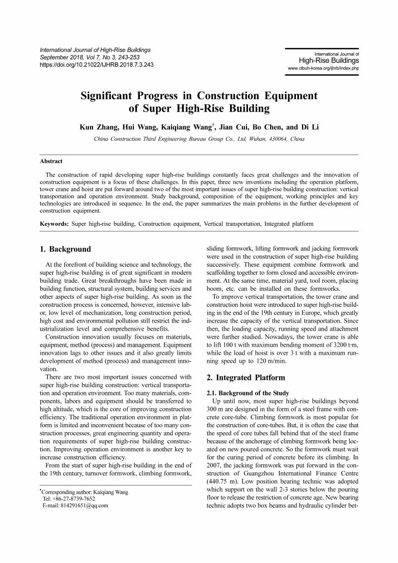
Box beam fulcrums have to rest on both sides of a tube,
so the micro-convex fulcrum (Fig. 1(a)) was invented in
the construction of Wuhan Center (438 m) in 2011 (Fig.
1(b)). This fulcrum only uses one piece of wall but the
bearing capacity can be hundreds of tons. “Micro convex
jacking formwork” involves more fulcrums distributed on
the outer walls of core tube. Therefore, the bearing capa-
city and rigidity of formwork are further improved and it
can integrate more facilities and be safer at height.
The next critical problem of formwork is the conflicts
with tower cranes in layout and operation. Fixing tower
crane directly on the platform or sharing supporting and
power system of formwork with the tower crane are two
different ways to solve the problem. Relatively speaking,
the hoist and placing boom can be easily integrated into
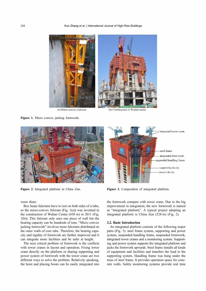
the formwork compare with tower crane. Due to the big
improvement in integration, the new formwork is named
as “integrated platform”. A typical project adopting an
integrated platform is China Zun (528 m) (Fig. 2).
2.2. Basic Introduction
An integrated platform consists of the following major
parts (Fig. 3): steel frame system, supporting and power
system, suspended handling frame, suspended formwork,
integrated tower cranes and a monitoring system. Support-
ing and power system supports the integrated platform and
jacks the formwork upwards. Steel frame installs all kinds
of equipment and facilities and transfers the load to the
supporting system. Handling frame was hung under the
truss of steel frame. It provides operation space for conc-
rete walls. Safety monitoring systems provide real time
Figure 1. Micro convex jacking formwork.
Figure 2. Integrated platform in China Zun. Figure 3. Composition of integrated platform.
Significant Progress in Construction Equipment of Super High-Rise Building 245
monitoring of integrated platform to guarantee the safe
operation.
An integrated platform usually owns 8 to 14 supporting
units with a vertical load capacity of up to 600 t for one
unit and in total about 5000 t for the whole supporting
system. The high bearing (up to 600 t) and long stroke
(up to 6 m) hydraulic cylinder was set in every supporting
unit. Synchronous jacking takes only 2-3 hours to push
the platform up to a new floor at a time.
The integrated platform covers the entire core tube with
projected area over 1000 m2 while spanning 4.5 floors in
vertical with 10 operation levels. A steel plate installation,
reinforcement assembling, formwork erecting, concrete
pouring and concrete curing can be carried out simulta-
neously in the different operating layers.
Big operation spaces and great bearing capacity of inte-
grated platform allow it to contain almost all the equip-
ment and facilities, and construction technologies of the
core tube, which can achieve the optimal allocation of res-
ources and highly efficient construction. The hoist can
reach to any levels of the integrated platform. The exter-
nal transportation depending on hoist cooperating with
the perfect inner one can realize the rapid flow of labors
and materials.
2.3. Key Technologies
2.3.1. Supporting and Jacking System
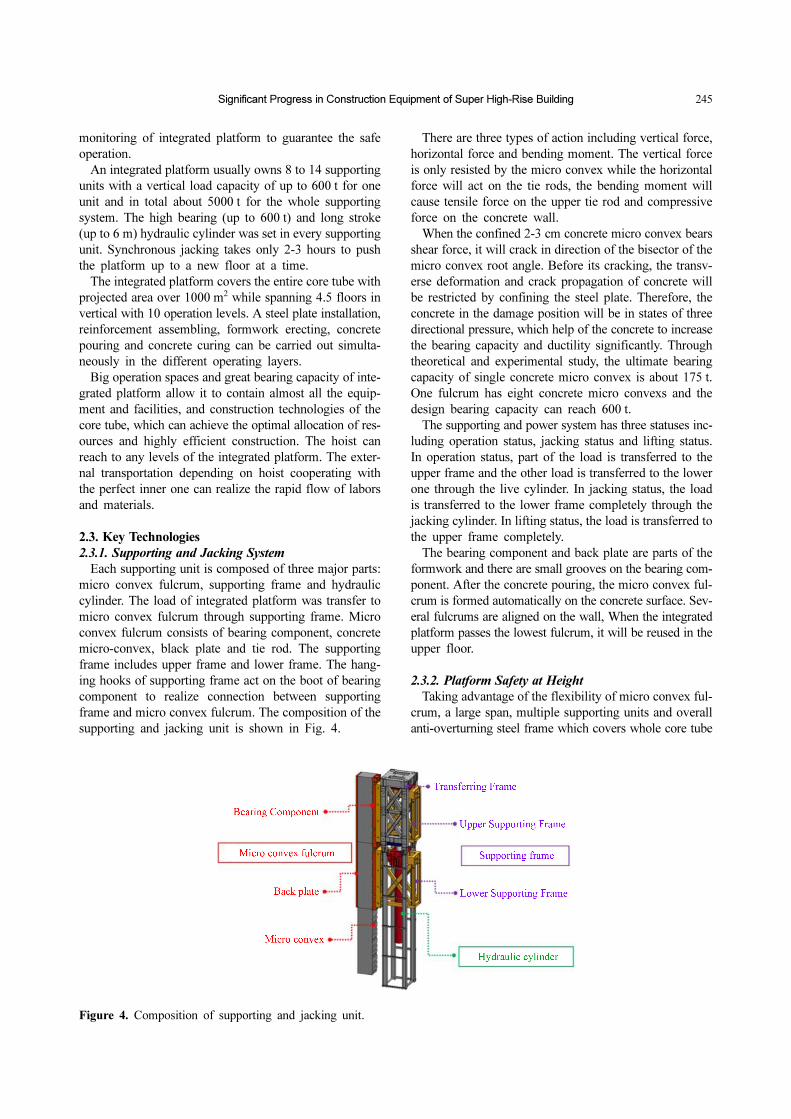
Each supporting unit is composed of three major parts:
micro convex fulcrum, supporting frame and hydraulic
cylinder. The load of integrated platform was transfer to
micro convex fulcrum through supporting frame. Micro
convex fulcrum consists of bearing component, concrete
micro-convex, black plate and tie rod. The supporting
frame includes upper frame and lower frame. The hang-
ing hooks of supporting frame act on the boot of bearing
component to realize connection between supporting
frame and micro convex fulcrum. The composition of the
supporting and jacking unit is shown in Fig. 4.
There are three types of action including vertical force,
horizontal force and bending moment. The vertical force
is only resisted by the micro convex while the horizontal
force will act on the tie rods, the bending moment will
cause tensile force on the upper tie rod and compressive
force on the concrete wall.
When the confined 2-3 cm concrete micro convex bears
shear force, it will crack in direction of the bisector of the
micro convex root angle. Before its cracking, the transv-
erse deformation and crack propagation of concrete will
be restricted by confining the steel plate. Therefore, the
concrete in the damage position will be in states of three
directional pressure, which help of the concrete to increase
the bearing capacity and ductility significantly. Through
theoretical and experimental study, the ultimate bearing
capacity of single concrete micro convex is about 175 t.
One fulcrum has eight concrete micro convexs and the
design bearing capacity can reach 600 t.
The supporting and power system has three statuses inc-
luding operation status, jacking status and lifting status.
In operation status, part of the load is transferred to the
upper frame and the other load is transferred to the lower
one through the live cylinder. In jacking status, the load
is transferred to the lower frame completely through the
jacking cylinder. In lifting status, the load is transferred to
the upper frame completely.
The bearing component and back plate are parts of the
formwork and there are small grooves on the bearing com-
ponent. After the concrete pouring, the micro convex ful-
crum is formed automatically on the concrete surface. Sev-
eral fulcrums are aligned on the wall, When the integrated
platform passes the lowest fulcrum, it will be reused in the
upper floor.
2.3.2. Platform Safety at Height
Taking advantage of the flexibility of micro convex ful-
crum, a large span, multiple supporting units and overall
anti-overturning steel frame which covers whole core tube
Figure 4. Composition of supporting and jacking unit.

246 Kun Zhang et al. | International Journal of High-Rise Buildings
is established. The bearing capacity can be 2000 t or more
and the structure can resist a class 14 wind.
To fit for the deflection of micro convex fulcrum caused
by the construction error, a hook guide mechanism was
invented by using a wedge boot of bearing component to
help hook move into a bearing component automatically.
To adjust the unbalanced force between different support-
ing units because of construction error, uneven stacking
and jack error of cylinder, the disc spring device is put on
the top of upper supporting frame, which can adjust hun-
dreds of tons.
The monitoring system checks operating status of the
integrated platform through various sensors, including
strain, verticality, levelness wind speed and temperature.
Monitoring software can collect, store, analyze and display
the information fed back from the senses and send an alarm
in advance (Fig. 5).
2.3.3. Integration of Tower Crane
Tower cranes in different level can be integrated into the
platform from ZSL380, ZSL1150 to ZSL2700 (bending
moment up to 2700 t·m). The small tower crane such as
ZSL380 can be erected directly on the top of a steel plat-
form.
As soon as the big tower crane is concerned, there are
three tie-backs, the top tie-back is a screw jack fixed on
the top of the platform and it provides horizontal support
for the tower crane (Fig. 6). The middle and lower tie-
back are fixed on tower crane mast and there are both
puller cylinders and roller cylinders around mast. The
middle tie-back is rest on the supporting system and trans-
fer vertical load of tower crane to supporting system. Both
middle and lower tie-backs transfer horizontal load to the
concrete walls.
When the tower crane is working, release the top tie-back
and push the lower and middle puller cylinders against
the wall. The middle tie-back transfers both vertical and
horizontal load while the lower tie-back transfers the hori-
zontal load so that tie-backs could work together and res-
ist the vertical, horizontal force and bending moment.
Before jacking up, people must balance the tower crane
with weight so that its center of gravity is move to its cen-
troid, then release the puller cylinders at the lower and
middle part while extend the screw jack and roller cylin-
ders until they are 1-2 cm close to the wall. During the
process of jacking, these three tie-backs will provide hori-
Figure 6. Integration of big tower crane.
Figure 5. Monitoring system.

Significant Progress in Construction Equipment of Super High-Rise Building 247
zontal support for the tower crane in case of strong wind
or bad weather.
3. Crane Slewing System
3.1. Background of the Study
The vertical transportation of components and materials
for super high-rise building construction mainly rely on the
tower crane. Because of the distribution of components for
the typical structure system (steel frame and core tube),
the defects of traditional method are obvious.
1) The large tower crane must be selected because of
mega columns those located on the perimeters of the tower
with only 5% of all components. At the same time, to keep
a safety distance between tower cranes, multiple tower
cranes cannot operate together efficiently.
2) Both in plane and vertical layouts the tower crane
will interfere with other construction equipment such as
formwork and hoist, which will lower efficiency in cons-
truction. The jacking, steel beam cycling and welding of
tower crane also waste construction period.
3.2. Basic Introduction
To solve the above problems, absorbing the idea of the
rotating table, a crane slewing system was put forward
(Fig. 7). The crane slewing system integrates all the tower
cranes at different levels on one platform which is able to
slew around the core tube. Several obvious advantages can
be gotten easily:
1) Taking advantage of the slewing function, the cover
area of tower cranes is increased. Therefore, the tower
cranes combination is optimized, big, middle and small
tower cranes are combined together and perform most
efficiently.
2) All the tower cranes will be jacked together with the
slewing system. The change of structure will be easy to
fit for tower cranes.
3) Every tower cranes would be the backup of others to
some extent.
Crane slewing system is composed by four important
parts: supporting and power system, slewing driving sys-
tem, steel frame and control system (Fig. 8). Supporting
and power system bear the load and supply power for
jacking which is similar with that of integrated platform.
A slewing driving system directly holds the steel frame
and supplies the power for slewing. Steel frame with the
shape of “X” integrates all the tower cranes on the top of
itself. A crane slewing system just like a mega-tower crane
which are supported on and climb along the core-tube.
The big slewing device on the top of the crane slewing
system is a multifunctional X-shape arm (Fig. 9).
Figure 8. Composition of crane slewing system.
Figure 7. Crane slewing system.

248 Kun Zhang et al. | International Journal of High-Rise Buildings
3.3. Key Technologies
3.3.1. Slewing Driving System
The slewing driving system is composed of upper joint,
slewing bearing and lower joint (Fig 10). The upper joint
directly holds up the steel frame, while the slewing bear-
ing fixed with the lower joint that connects with the upstand
(Fig 11). Two hydraulic motors provides the moment for
slewing. The core part is the slewing bearing which is dri-
ven by hydraulic motors. This bearing is carefully designed
to take up to 2000 t axial loading, 9000 t·m turning mom-
Figure 10. Composition of slewing system.
Figure 9. X form steel frame
Figure 11. Slewing bearing and hydraulic motor.
Significant Progress in Construction Equipment of Super High-Rise Building 249
ent and 60 t radial loading.
3.3.2. Lifting Organization
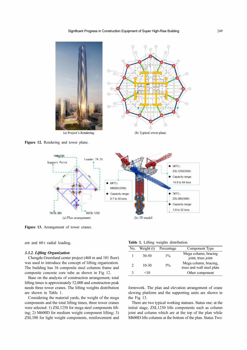
Chengdu Greenland center project (468 m and 101 floor)
was used to introduce the concept of lifting organization.
The building has 16 composite steel columns frame and
composite concrete core tube as shown in Fig 12.
Base on the analysis of construction arrangement, total
lifting times is approximately 52,000 and construction peak
needs three tower cranes. The lifting weights distribution
are shown in Table 1.
Considering the material yards, the weight of the mega
components and the total lifting times, three tower cranes
were selected: 1) ZSL1250 for mega steel components lift-
ing; 2) M600D for medium weight component lifting; 3)
ZSL380 for light weight components, reinforcement and
formwork. The plan and elevation arrangement of crane
slewing platform and the supporting units are shown in
the Fig 13.
There are two typical working statuses. Status one: at the
initial stage, ZSL1250 lifts components such as column
joint and column which are at the top of the plan while
M600D lifts columns at the bottom of the plan. Status Two:
Figure 12. Rendering and tower plane.
Figure 13. Arrangement of tower cranes.
Table 1. Lifting weights distribution
No. Weight (t) Percentage Component Type
1 30-50 1%Mega column, bracing
joint, truss joint
2 10-30 5%Mega column, bracing,
truss and wall steel plate
3 <10 Other component

250 Kun Zhang et al. | International Journal of High-Rise Buildings
the platform slew 180° clockwise, ZSL1250 can reach the
giant joints at the bottom of the plan.
4. Circular Hoist
4.1. Background of the Study
In the construction of super high-rise building, there are
usually more than ten hoists. Too many hoists occupy large
operation area of different majors such as masonry and
curtain wall. Some projects adopt an extra channel mast to
decrease the occupation of hoists, but the cost rises accord-
ingly. Both of these two ways will extend construction
period. On the other hand, increase running speed and en-
large the dimension of the cage to increase transportation
capacity are of limited effectiveness.
4.2. Basic Introduction
Accordingly, a new hoist system named as circular hoist
was proposed in which multi-cages running along one sin-
gle mast. The cages will run upwards on one side of the
mast to certain level and slew 180 degree then go down
along the other side of the mast, as shown in the following
Figs. 14 and 15. It resembles a vertical subway that con-
tains many cages running in the same circular rails.
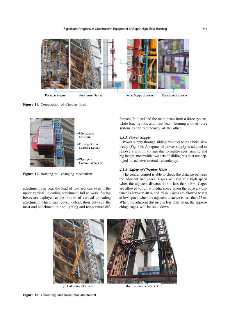
A circular hoist consists of a rotating system, an attach-
ment system, power supply system, monitoring and dis-
patching system (Fig. 16). A rotating System is the core
part of the circular hoist, it helps hoist to slew at height
and transfers the load to a lower mast. There are 2 types
of attachment, the first one is a traditional horizontal atta-
chment, and the other is a vertical unloading attachment;
the vertical unloading attachment will transfer the load of
segments between 2 vertical unloading attachments.
Through sliding a bus duct, a drop in voltage and cable
break is not a problem for power supply. Central control
room can monitor operation status of all cages to achieve
control and effective managements of all cages in time.
4.3. Key Technologies
4.3.1. Rotating System
Rotating system includes mechanical structure, driving
and positioning system and electric control system (Fig.
17). Mechanism includes slewing frame and load bearing
shaft. Slewing frame carrying hoist move around load bear-
ing shaft while the vertical load path is exist. Slewing
frame is driven by servo motor; the maximum speed is
1.5RPM. Positioning device including encoder, adjustable
pinion and gear ring, the accuracy is 0.03 mm.
4.3.2. Vertical Unloading Attachments
Except of traditional horizontal attachment, the new ver-
tical unloading attachment is used in circular hoist that
including pull rod, main beam, bracing rods and Spring
boxes (Fig. 18). The vertical load of segmental track bet-
ween two vertical unloading attachments is transferred to
these attachments directly. So the new hoist can be erected
with longer a mast and more hoists. The vertical unloading
Figure 15. Circular hoist.
Figure 14. Principle of circular hoist.
Significant Progress in Construction Equipment of Super High-Rise Building 251
attachment can bear the load of two sections even if the
upper vertical unloading attachment fail to work. Spring
boxes are deployed at the bottom of vertical unloading
attachment which can reduce deformation between the
mast and attachment due to lighting and temperature dif-
ference. Pull rod and the main beam form a force system,
while bracing rods and main beam forming another force
system as the redundancy of the other.
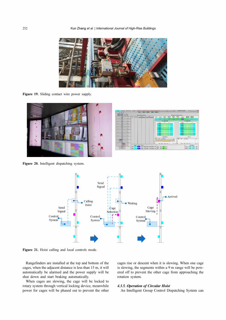
4.3.3. Power Supply
Power supply through sliding bus duct helps a hoist slew
freely (Fig. 19). A segmental power supply is adopted to
resolve a drop in voltage due to multi-cages running and
big height, meanwhile two sets of sliding bus duct are dep-
loyed to achieve mutual redundancy.
4.3.4. Safety of Circular Hoist
The central control is able to check the distance between
the adjacent two cages. Cages will run at a high speed
when the adjacent distance is not less than 40 m. Cages
are allowed to run at media speed when the adjacent dis-
tance is between 40 m and 25 m. Cages are allowed to run
at low speed when the adjacent distance is less than 25 m.
When the adjacent distance is less than 15 m, the approa-
ching cages will be shut down.
Figure 16. Composition of Circular hoist.
Figure 17. Rotating rail changing mechanism.
Figure 18. Unloading and horizontal attachment.
252 Kun Zhang et al. | International Journal of High-Rise Buildings
Rangefinders are installed at the top and bottom of the
cages, when the adjacent distance is less than 15 m, it will
automatically be alarmed and the power supply will be
shut down and start braking automatically.
When cages are slewing, the cage will be locked to
rotary system through vertical locking device, meanwhile
power for cages will be phased out to prevent the other
cages rise or descent when it is slewing. When one cage
is slewing, the segments within a 9 m range will be pow-
ered off to prevent the other cage from approaching the
rotation system.
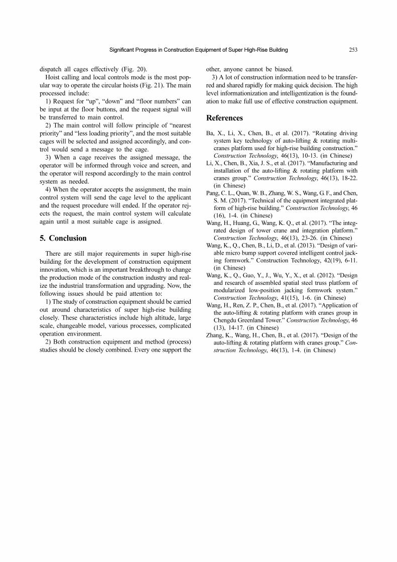
4.3.5. Operation of Circular Hoist
An Intelligent Group Control Dispatching System can
Figure 20. Intelligent dispatching system.
Figure 19. Sliding contact wire power supply.
Figure 21. Hoist calling and local controls mode.
Significant Progress in Construction Equipment of Super High-Rise Building 253
dispatch all cages effectively (Fig. 20).
Hoist calling and local controls mode is the most pop-
ular way to operate the circular hoists (Fig. 21). The main
processed include:
1) Request for “up”, “down” and “floor numbers” can
be input at the floor buttons, and the request signal will
be transferred to main control.
2) The main control will follow principle of “nearest
priority” and “less loading priority”, and the most suitable
cages will be selected and assigned accordingly, and con-
trol would send a message to the cage.
3) When a cage receives the assigned message, the
operator will be informed through voice and screen, and
the operator will respond accordingly to the main control
system as needed.
4) When the operator accepts the assignment, the main
control system will send the cage level to the applicant
and the request procedure will ended. If the operator rej-
ects the request, the main control system will calculate
again until a most suitable cage is assigned.
5. Conclusion
There are still major requirements in super high-rise
building for the development of construction equipment
innovation, which is an important breakthrough to change
the production mode of the construction industry and real-
ize the industrial transformation and upgrading. Now, the
following issues should be paid attention to:
1) The study of construction equipment should be carried
out around characteristics of super high-rise building
closely. These characteristics include high altitude, large
scale, changeable model, various processes, complicated
operation environment.
2) Both construction equipment and method (process)
studies should be closely combined. Every one support the
other, anyone cannot be biased.
3) A lot of construction information need to be transfer-
red and shared rapidly for making quick decision. The high
level informationization and intelligentization is the found-
ation to make full use of effective construction equipment.
References
Ba, X., Li, X., Chen, B., et al. (2017). “Rotating driving
system key technology of auto-lifting & rotating multi-
cranes platform used for high-rise building construction.”
Construction Technology, 46(13), 10-13. (in Chinese)
Li, X., Chen, B., Xia, J. S., et al. (2017). “Manufacturing and
installation of the auto-lifting & rotating platform with
cranes group.” Construction Technology, 46(13), 18-22.
(in Chinese)
Pang, C. L., Quan, W. B., Zhang, W. S., Wang, G. F., and Chen,
S. M. (2017). “Technical of the equipment integrated plat-
form of high-rise building.” Construction Technology, 46
(16), 1-4. (in Chinese)
Wang, H., Huang, G., Wang, K. Q., et al. (2017). “The integ-
rated design of tower crane and integration platform.”
Construction Technology, 46(13), 23-26. (in Chinese)
Wang, K., Q., Chen, B., Li, D., et al. (2013). “Design of vari-
able micro bump support covered intelligent control jack-
ing formwork.” Construction Technology, 42(19), 6-11.
(in Chinese)
Wang, K., Q., Guo, Y., J., Wu, Y., X., et al. (2012). “Design
and research of assembled spatial steel truss platform of
modularized low-position jacking formwork system.”
Construction Technology, 41(15), 1-6. (in Chinese)
Wang, H., Ren, Z. P., Chen, B., et al. (2017). “Application of
the auto-lifting & rotating platform with cranes group in
Chengdu Greenland Tower.” Construction Technology, 46
(13), 14-17. (in Chinese)
Zhang, K., Wang, H., Chen, B., et al. (2017). “Design of the
auto-lifting & rotating platform with cranes group.” Con-
struction Technology, 46(13), 1-4. (in Chinese)